


VDO SERIES-Z
FOR CYCLING
INSTRUCTION MANUAL / BEDIENUNGSANLEITUNG / MANUEL D´INSTALLATION
ET D´UTILISATION / HANDLEIDING / MANUALE D´INSTALLAZIONE E FUNZIONAMENTO INSTRUKCJA OBSLUGI LICZNIKA / INSTALACION Y OPERACIÓN MANUAL
|
My Settings |
|
|
|
|
|
|
|
|
|
|
||||||
|
|
|
|
|
|
|
|
|
|
|
|
|
|
|
|
|
|
|
AGE: |
|
|
|
|
|
|
WEIGHT: |
|
|
|
|
|
|
MAX HEARTRATE: |
|
|
|
|
|
|
|
|
|
|
|
|
|
|
|
|
|
|
|
|
|
|
|
|
|
|
|
|
|
|
|
|
|
|
|
|
||
|
LIMIT 1: |
|
LOW: |
|
|
|
|
|
|
HIGH: |
|
|
|
|
|
||
|
|
|
|
|
|
|
|
|
|
|
|
|
|
||||
|
LIMIT 2: |
|
LOW: |
|
|
|
|
|
|
HIGH: |
|
|
|
|
|
||
|
|
|
|
|
|
|
|
|
|
|
|
|
|
||||
|
LIMIT 3: |
|
LOW: |
|
|
|
|
|
|
HIGH: |
|
|
|
|
|
||
|
|
|
|
|
|
|
|
|
|
|
|
||||||
|
RECOVERY TIME: |
|
|
|
|
|
RECOVERY PULSE: |
|
|
|
|
||||||
|
|
|
|
|
|
|
|
|
|
|
|
||||||
|
BIKE 1 WEIGHT: |
|
|
|
|
|
BIKE 2 WEIGHT: |
|
|
|
|
||||||
|
|
|
|
|
|
|
|
|
|
|
|
||||||
|
|
|
|
|
|
|
|
|
|
|
|
||||||
|
BIKE 1 WHEELSIZE: |
|
|
|
|
|
BIKE 2 WHEELSIZE: |
|
|
|
|
||||||
|
|
|
|
|
|
|
|
|
|
|
|
||||||
|
BIKE 1 SERVICE INTERVALL: |
|
|
|
|
|
BIKE 2 SERVICE INTERVALL: |
|
|
|
|
||||||
|
|
|
|
|
|
|
|
|
|
|
|
|
|
|
|
|
|
|
HOME ALTITUDE: |
|
|
|
|
|
|
|
|
|
|
|
|
||||
|
|
|
|
|
|
|
|
|
|
|
|
|
|||||
|
FURTHER SETTINGS: |
|
|
|
|
|
|
|
|
|
|
|
|
||||
|
|
|
|
|
|
|
|
|
|
|
|
|
|
|
|
|
|
|
|
|
|
|
|
|
|
|
|
|
|
|
|
|
|
|
|

Picturebook
P01
ONLY FOR MODELS
Z2 PC-LINK / Z3 PC-LINK
CD-ROM
PC-Sport
*
8x
*Watch out: old batteries require special disposal 

 Please read instructions for end-off-life disposal treatment
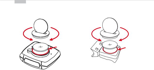
Picturebook
P02
OPEN |
CLOSE |
OPEN |
CLOSE |
|
! |
|
! |
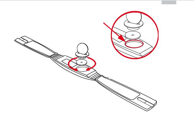
Picturebook
P03
ONLY FOR
MODELS
Z2/Z2 PC-LINK
Z3/Z3 PC-LINK
!
OPEN |
CLOSE |
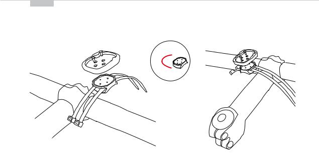
Picturebook
P04/05
90° 
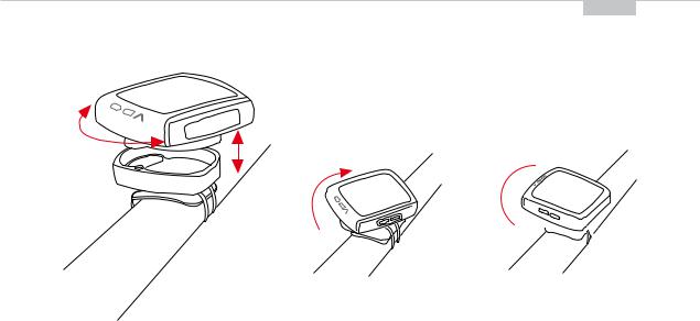
Picturebook
P06
LOCK
UNLOCK
2.CLICK
1.LOCK
2.UNLOCK 

Picturebook
P07
1-5 mm
Picturebook
P08
ONLY FOR
MODELS
Z2/Z2 PC-LINK Z3/Z3 PC-LINK
Picturebook
|
P09 |
|
P09-2 |
|
CLOSE
OPEN
Picturebook
P10
1x
WS in mm / inch
Tire size |
|
WS in mm KMH |
WS in inch MPH |
|
47-305 |
16x1,75 |
1272 |
50,1 |
|
47-406 |
20x1,75 |
1590 |
62,6 |
|
34-540 |
24x1 3/8 |
1948 |
76,7 |
|
47-507 |
24x1,75 |
1907 |
75,1 |
|
23-571 |
26x1 |
1973 |
77,7 |
|
40-559 |
26x1,5 |
2026 |
79,8 |
|
44-559 |
26x1,6 |
2051 |
80,7 |
|
47-559 |
26x1,75 |
2055 |
80,9 |
|
50-559 |
26x1,9 |
2060 |
81,1 |
|
n/a |
26 x 1,95 |
2070 |
81,5 |
|
54-559 |
26x2,00 |
2075 |
81,7 |
|
n/a |
26 x 2,1 |
2080 |
81,9 |
|
57-559 |
26x2,125 |
2133 |
84,0 |
|
37-590 |
26x1 3/8 |
2105 |
82,9 |
|
|
|
|
|
|
Tire size |
|
WS in mm KMH |
WS in inch MPH |
20-571 |
26x3/4 |
1954 |
76,9 |
32-630 |
27x1 1/4 |
2199 |
86,6 |
40-622 |
28x1,5 |
2224 |
87,6 |
47-622 |
28x1,75 |
2268 |
89,3 |
40-635 |
28x1 1/2 |
2265 |
89,2 |
37-622 |
28x1 3/8 |
2205 |
86,8 |
18-622 |
700x18C |
2102 |
82,8 |
20-622 |
700x20C |
2114 |
83,2 |
23-622 |
700x23C |
2133 |
84,0 |
25-622 |
700x25C |
2146 |
84,5 |
28-622 |
700x28C |
2149 |
84,6 |
32-622 |
700x32C |
2174 |
85,6 |
37-622 |
700x37C |
2205 |
86,8 |
40-622 |
700x40C |
2224 |
87,6 |
|
|
|
|
Picturebook
P11
ONLY FOR
MODELS
Z2 PC-LINK
Z3 PC-LINK

EN
Congratulations
With your selection of a VDO Z3 you have opted for high-quality sports information computer. In order to fully benefit from the potential of the computer, we recommend that you carefully read this manual. It contains all operating instructions and many useful tips.
We extend our best wishes for enjoyment and satisfaction when riding with your VDO computer.
VDO Cyclecomputing Cycle Parts GmbH
Package contents >>> P01
First, please ensure that the contents of this package are complete: 1 VDO computer Z3
1 VDO speed transmitter
1 VDO pulse-chest belt incl. elastic strap, incl. battery 1 battery for computer, 3 V type 2032
1 handlebar holder
1 wrist band holder
1 lock for the wrist band holder
1 spoke magnet
8 cable ties
Optional extension set:
VDO cadence transmitter
>>> P...
Reference to the appropriate pages in the picture book.This is where the content is again presented in picture form, e.g.:
>>> P01  P01 page 1 in the picture book
4

INSTRUCTION MANUAL
TABLE OF CONTENTS
1.1.GENERAL
1.2.IMPORTANT INSTRUCTIONS FOR THE DIGITAL WIRELESS SYSTEM
1.3.Control system - operation
1.3.1.Operating mode
1.3.2.Setting mode
1.4.The display
1.5.Extension options & accessories
2. INSTALLATION
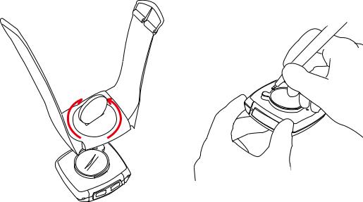
2.1.Battery installation
2.1.1.Battery installation - computer and speed/cadence transmitter
2.1.2.Battery installation pulse-chest belt.
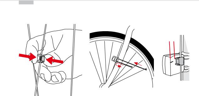
2.2.Installation - holder/computer/transmitter/magnet
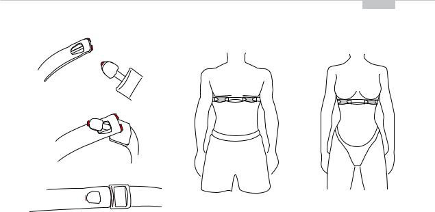
2.3.Putting on the pulse-chest belt
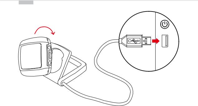
2.4.Mounting the computer on the wrist band
3. INITIAL OPERATION
3.1.Initial operation, AC-button
3.2.Language selection
3.3.Manual pairing - INITIAL operation wireless system
3.3.1.Initial operation - pulse transmitter
3.3.2.Initial operation - speed transmitter
3.3.3.Initial operation - cadence transmitter
4. GENERAL SETTINGS
4.1.Setting the language
4.2.Setting time & date
4.3.Setting the alarm, alarm clock
5. BICYCLE FUNCTION SETTINGS
5.1.Measuring and setting wheel size/s
5.2.Changing wheel size
5.3.Setting total kilometers
5.4.Bike check / service interval
6. PERSONAL SETTINGS IMPORTANT NOTE
The personal settings are prerequisite for calculating maximum pulse, training zones, and calorie consumption.
Ensure that you make the personal settings first so that you can fully utilize the possibilities offered by the computer.
6.1.Personal settings with manual max. pulse entry
6.2.Personal settings with automatic max. pulse calculation
7.PULSE FUNCTION SETTINGS
7.1.Automatic calculation of pulse limit values
7.2.Manual entry of pulse limit values
7.3.Selecting the training range
7.4.Setting the recovery measurement (pulse or time)
7.5.Power calculation in watt
5

EN
8. ALTITUDE FUNCTION SETTINGS
8.1.Setting the home altitude (starting altitude)
8.2.Setting the actual altitude
8.3.Annual uphill altitude difference bike 1 and bike 2 and walk mode
8.4.Annual downhill altitude difference bike 1 and bike 2 and walk mode
9. RESET MODE
9.1.Resetting trip data
9.2.Reset total ride time
9.3.Resetting the total distance meter
9.4.Resetting the Navigator
9.5.Resetting to factory settings (AC button)
10. OPERATION MODE SELECTION
Selecting the operation mode: Bike mode or walk mode
11. OPERATION MODE
11.1.Function overview
11.2.Fast pairing after interruption > 15 minutes
11.3.GETTING STARTED
11.3.0.The permanent functions in the display
11.3.1.to 11.3.35. Quick overview - functions/operation/reset/max. values
12. RIDING WITH THE NAVIGATOR
12.1.Selecting Navigator mode
12.2.Resetting the Navigator at the orientation point
13. THE TIMING FUNCTIONS
13.1.Selecting the timing function
13.2.Setting the timer (when selecting timer 1 or timer 2 or timer 1 + 2)
13.3.Setting timer 1 + 2 repeats (when selecting timer 1 + 2)
13.4.Setting the countdown (when selecting countdown timer)
13.5.Lap timer
13.6.Stopwatch
14. TRAINING WITH THE PULSE FUNCTIONS
14.1.Training with the stopwatch
14.2.Training with timer 1 / timer 2 / timer 1+2
14.3.Training with the countdown timer
14.4.Training with the lap timer
15.SLEEP MODE
16.TROUBLESHOOTING
17.GUARANTEE CONDITIONS
18.TECHNICAL SPECIFICATIONS
6

INSTRUCTION MANUAL
1.1.GENERAL
1.2.IMPORTANT INSTRUCTIONS FOR THE DIGITAL WIRELESS SYSTEM
Your VDO series Z3 works entirely without cable; it works with triple digital wireless transmission based on well-established ANT+Sport® wireless protocol. The ANT+Sport® wireless protocol has already been successfully implemented by manufacturers such as Garmin, Specialized, and Suunto. Speed signals, cadence signals (optional), as well as heart rate data are transmitted to the respective receiver (computer) as digital and coded signals. Signal coding ensures that only the data of your own pulse, speed, and cadence (optional) transmitters are processed (this is advantageous when riding in a group).
The ANT+Sport digital technology is significantly more reliable than the technology of older analog systems. The ANT+Sport technology uses standard industrial wireless components, and it can best be compared to the technology used in modern WLAN networks. The connection between transmitter and receiver is more stable, and subject to significantly less frequent malfunction, and it is virtually completely safeguarded from data loss.
The speed transmitter has a memory component that buffers data every 65 sec. Thus no data is lost if there is a malfunction lasting for this duration.After the malfunction this data will be resent to the computer. Subsequently the following data will be updated:
Daily distance
Ride time
Average speed
Navigator
Total distance
Total ride time
After a malfunction the data can change suddenly = updating the computer. Initial operation of a completely digital system requires somewhat more care than does initial operation of conventional analog systems. The first time batteries are inserted, or after a battery change, the transmitter automatically generates a new code. The computer has to learn this code. To do this you must execute a DIG CONNECT SET. Strictly follow the instructions in chapter 3.3 to do this.
ATTENTION: Your VDO computer is not suitable for use on motorcycles.
1.3. CONTROL SYSTEM - OPERATION
The control system of your computer is based on dual assignment of the 4 main buttons. In this regard the devices distinguishes between operation mode and setting mode.
7
EN
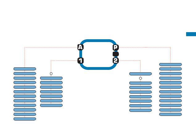
1.3.1. OPERATION MODE - use this mode to display all information Button assignment is shown on the housing.
Displaying all altitude measuring functions
|
|
Displaying the bike |
|
|
functions 1 |
|
ALTI UP |
|
K |
DIST UP |
K |
|
TRIP MAX |
TRIP DIST |
K |
AVG CLIMB |
RIDE TIME |
K |
MAX CLIMB |
AVG SPEED |
|
TOTAL UP (1 or 2) |
MAX SPEED |
|
ALTI MAX (1 or 2) |
CADENCE |
|
ALTI DOWN |
CAD AVG |
K |
DIST DOWN |
CAD MAX |
KAVG DOWN
KMAX DOWN TOTAL DOWN (1/2)
K Not in walk mode !
OPERATION MODE
Z3
Displaying all pulse measurement functions and interval data stored
 Manual start/stop of the stopwatch and of all other timers
Displaying the bike functions 2
CLOCK
K
NAVIGATOR
ODO BIKE 1
ODO BIKE 2
ODOTOTAL
TIME BIKE1
TIME BIKE2
TOTALTIME
TIMER
AVG PULSE
MAX PULSE
PULSE MAX%
LIMIT
TIME IN
TIME ABOVE
TIME BELOW
LAP REC
CALORIE
KPOWER WATT RECOV TIME
8
INSTRUCTION MANUAL
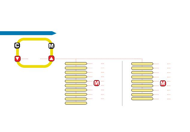
1.3.2. SETTING MODE - use this mode to make all settings. The assignment of buttons is on the buttons
To go to setting mode: |
Press button ç for 3 seconds |
|
|
SETTING MODE |
|
|
|
or |
|
|
|
Z3 |
LANGUAGE SELECT |
Chap. 4.1. |
|
NAVIGATOR SET |
Chap. 12.1. |
||
|
|||
|
WHEELSIZE SET |
Chap. 5.1. |
|
|
WHEELSIZE CHANGE |
Chap. 5.2. |
|
|
CLOCK SET |
Chap. 4.2. |
|
|
ALARM SET |
Chap. 4.3. |
|
|
TIMER SETTINGS |
Chap. 13.1. |
|
|
ODOMETER SET |
Chap. 5.3. |
|
|
PULSE LIMIT SETTINGS |
Chap. 7.1. |
|
|
RECOVERY SET |
Chap. 7.4. |
HOME ALTI SET |
Chap. 8.1. |
ACTUAL ALTI SET |
Chap. 8.2. |
ALTI UP SET |
Chap. 8.3. |
ALTI DOWN SET |
Chap. 8.4. |
PERSON DATA SET |
Chap. 6.1. |
OP MODE SELECT |
Chap. 10. |
BIKE CHECK SET |
Chap. 5.4. |
POWER CALC SET |
Chap. 7.5. |
DIG-CONNECT SET |
Chap. 3.3. |
å (Once) = last step, or back one menu level (Hold) = return to start menu
‚: Select/confirm displayed option
In the highest menu level select the next menu level Page down within the menu level
∂ In SET mode (number flashes): Reduce number Page up within the menu level
ƒ: In SET mode (number flashes): Increase number
After subsequent confirmation of a setting the computer automatically returns to operation mode.
9
EN
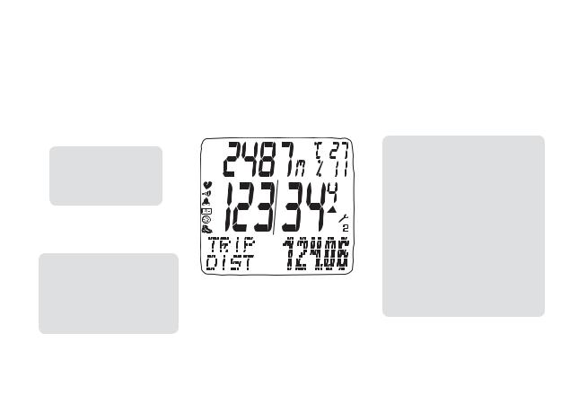
1.4. THE DISPLAY |
|
|
|
|
|
|
|||||||
The display of your VDO computer is comprised of three large areas. |
* If the computer is worn as a sport watch then the temperature can be |
||||||||||||
The following information is displayed in operation mode: |
falsified by body warmth. |
||||||||||||
|
|
|
|
|
|
|
|
|
|
|
|
|
|
|
|
|
|
|
|
|
|
|
|
|
|
|
MIDDLE BAR |
|
Header |
|
|
|
|
|
|
|
|
|
|
|
|
|
|
|
|
|
- Actual heart rate |
||||||||
|
|
|
|
|
|
|
|
|
|
|
|
||
|
- Actual altitude |
|
|
|
|
|
|
|
|
|
|
|
- Actual speed |
|
- Actual temperature |
|
|
|
|
|
|
|
|
- Heart icon for signal reception of chest belt |
|||
|
- Actual ascending gradient/ |
|
|
|
|
|
|
|
|
transmitter |
|||
|
descending gradient |
|
|
|
|
|
- Alarm icon when leaving the target heart |
||||||
|
|
|
|
|
|
|
|
|
|
|
|
|
rate range |
|
|
|
|
|
|
|
|
|
|
|
|
|
|
|
|
|
|
|
|
|
|
|
|
|
|
|
- Timing indicator for ongoing timing function |
|
|
|
|
|
|
|
|
|
|
|
|
|
- Indicator for set alarm/alarm clock |
|
|
|
|
|
|
|
|
|
|
|
|
|
- LAP recording indicator |
|
|
|
|
|
|
|
|
|
|
|
|
|
- Walk mode indicator |
3. Footer: DOT matrix full-text |
|
|
|
|
|
|
|
|
|
|
- Selection indicator bike 1 / bike 2 |
||
|
|
|
|
|
|
|
|
|
|
||||
- display of the selected/displayed |
|
|
|
|
|
|
|
|
|
|
- Arrow indicators for comparing the actual |
||
|
function |
|
|
|
|
|
speed to the average speed |
||||||
- In setting mode menu prompting |
|
|
|
|
|
- Service interval icon indicates that bike is |
|||||||
|
(chapter 5-8) provides informa- |
|
|
|
|
|
due for service |
||||||
|
tion about what is shown in the |
|
|
|
|
|
|
||||||
|
display. |
|
|
|
|
|
|
||||||
10
 Loading...