


M1.1 WR
ENGLISH
Installation video
Operating video
Settings video
www.vdocyclecomputing.com/service
1
M1.1 WR
Preface
Congratulations
In choosing a VDO computer, you have opted for high-quality device with first rate technology.
To optimally use the computer, we recommend that you read this manual carefully. It contains full operating instructions and many useful tips.
We hope you enjoy cycling with your VDO computer.
Cycle Parts GmbH
Pack contents
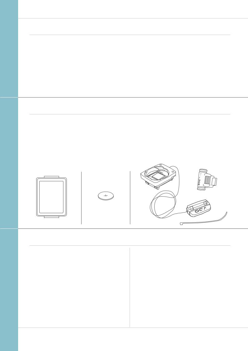
First, please ensure that the contents of this pack are complete:
1 VDO computer
1 battery for the computer
1 universal handlebar bracket with cable and sensor
1spoke magnet (clip magnet)
Cable ties for attaching the bracket and the sensor
1 quick-start instruction manual
Table of contents
Display............................................................................ |
03 |
Buttons ........................................................................... |
03 |
Functions ....................................................................... |
04 |
Operation while cycling ............................................... |
05 |
Sleep mode .................................................................... |
05 |
Attaching the handlebar bracket and the sensor ..... |
06 |
Inserting the computer into the bracket .................... |
07 |
Function testing ............................................................ |
07 |
Settings .......................................................................... |
08 |
Language ...................................................................... |
08 |
Wheel circumference ..................................................... |
09 |
Unit ................................................................................ |
12 |
Clock ............................................................................. |
13 |
Total distance ................................................................ |
16 |
Resetting trip data after the trip ................................. |
17 |
Battery status indicator ............................................... |
18 |
Replacing the battery in the computer ...................... |
18 |
Terms of guarantee ....................................................... |
19 |
Troubleshooting ............................................................ |
20 |
Technical specifications ............................................... |
20 |
2
M1.1 WR
Display
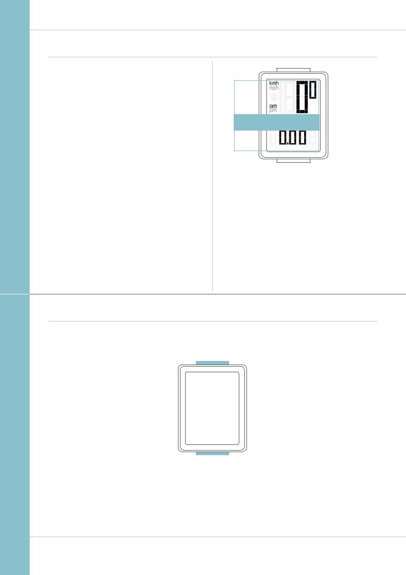
The VDO M1.1 WR has a large, easy-to-read display that can be divided into three areas.
–The top line of the display permanently indicates
the current speed. If the 12-hour clock format has been selected, “am” or “pm” appears next to the speed.
It also displays whether kmh or mph has been selected for the speed indicator.
–The middle line of the display shows the name of the selected function in clear text.
–The bottom line of the display shows the value for the selected function.
TOP
MIDDLE
BOTTOM
Buttons
The VDO M1.1 WR has two buttons
|
|
|
|
|
|
|
BIKE |
|
|
|
SET |
||
|
|
|||||
|
|
|||||
In function mode: |
|
|
|
In function mode: |
||
– Access functions |
|
|
|
– Scroll backwards through the functions |
||
– Reset trip data to zero |
|
|
|
– Open setting mode |
||
|
(press and hold) |
|
|
|
|
(press and hold) |
In setting mode: |
|
|
|
In setting mode: |
||
– Scroll in the setting menu |
|
|
|
– Open the setting |
||
– Change the data to be set |
|
|
|
– Confirm the setting once ready |
||
|
|
|
|
|
– Exit setting mode |
|
|
|
|
|
|
|
and return to function mode |
|
|
|
|
|
|
|
|
|
|
|
|
|
|
|
|
|
|
|
|
|
|
|
|
|
|
|
|
3
M1.1 WR
Functions
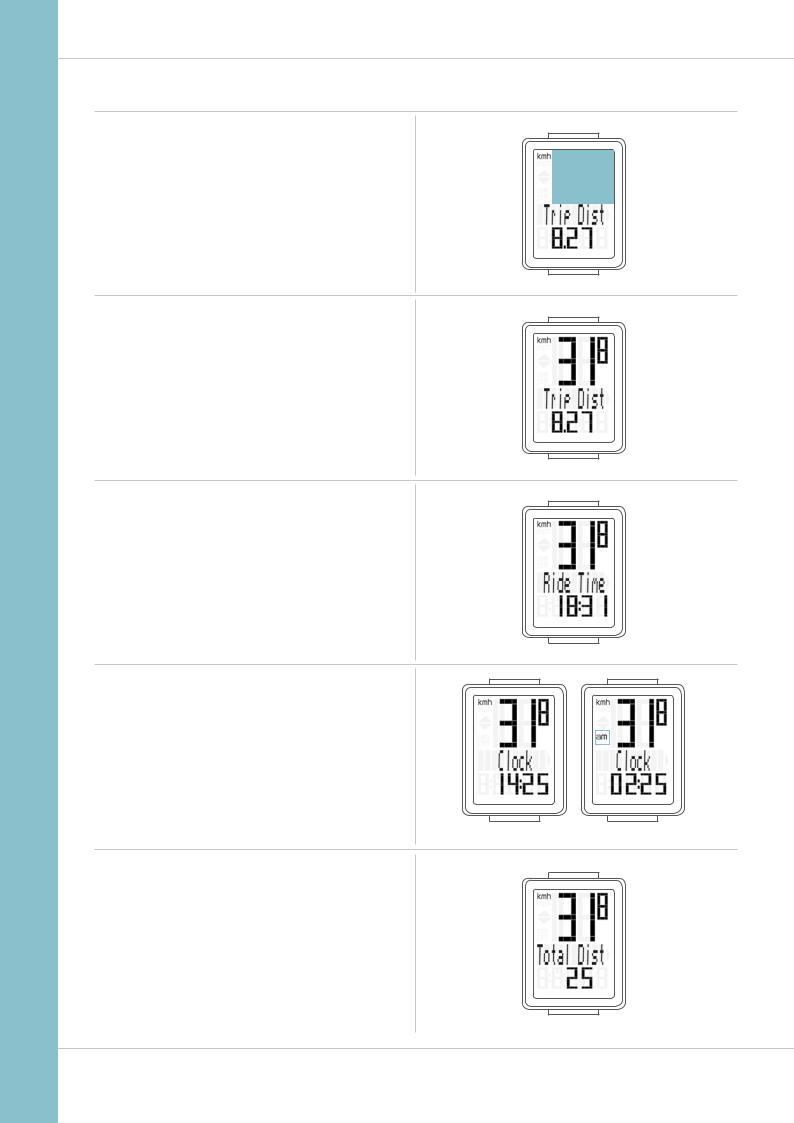
The VDO M1.1 WR has the following functions
Current speed
With a wheel circumference of 2,155 mm,
the maximum possible speed is 199 kmh or 124 mph.
Current distance
The current distance counts up to 999.99 km or miles.
If this maximum value is exceeded, the counter restarts the current distance calculation at zero.
Current ride time
The current ride time counts up to 99:59:59 HH:MM:SS. If this value is exceeded, the ride time counter restarts at zero.
Current time
(in 24-h or 12-h format)
24-H format |
12-H format |
Total distance
(Cumulative value for all trips)
The total distance counts up to 99,999 km or miles.
If this value is exceeded, the total distance counter restarts at zero.
If the unit is switched from miles to km and the conversion result is greater than 100,000 km, the counter is reset to zero.
4
M1.1 WR
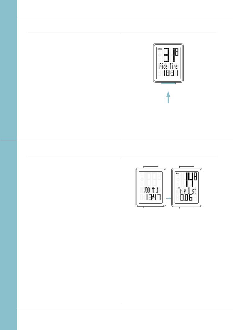
Operation while cycling
While cycling, the display functions can be accessed by |
SET |
pressing the BIKE button. |
|
|
|
|
|
Pressing the BIKE button shows the next function on the |
|
display. |
|
By pressing the SET button you can also scroll backwards |
|
through the functions. |
|
BIKE
1x
Sleep mode
If you take a break and the M1.1 WR is in the bracket, the computer switches to sleep mode after five minutes.
If you set off again after a break, the VDO M1.1 WR has an auto-start function.
The VDO M1.1 WR instantly switches back to the function mode and the current speed are once again displayed.
5

M1.1 WR
Attaching the bracket and the sensor
Start by attaching the sensor and the magnet.
STEP 1
Place the rubber shim under the sensor. Attach the sensor to the fork side that corresponds to the side on which you later want to attach the computer to the handlebars (right or left) using the cable ties supplied (loosely at first, do not pull tight just yet).
ATTENTION: the sensor mark on the sensor should point to the spokes. Depending on the space available, the sensor can be fitted to the front, inside or back of the fork.
STEP 2
Attach the spoke magnet to an outside spoke. The rod-shaped magnet core points toward the sensor with the VDO logo. Align the magnet with the sensor marking on the sensor
at a distance of approx. 1- 5 mm.
STEP 3
Align the sensor and the magnet in their final positions and fasten them in place: pull the cable ties tight and push the magnet in firmly.
STEP 4
Move the cable along the fork until it reaches the fork bridge. From there, wind the cable further along the brake line until it reaches the handlebars.
STEP 5
Decide whether you want to use handlebar or stem attachment and rotate the base of the handlebar bracket by 90° accordingly. To do so, undo the screws on the bracket, remove the foot and rotate it 90° then insert and tighten the screws again.
ATTENTION: do not overtighten the screws.
STEP 6
Guide the cable ties through the slot in the handlebar bracket, place around the handlebars or the stem and pull (do not pull tight just yet).
STEP 7
For handlebar attachment: align the computer angle to achieve optimum readability.
Now pull the cable ties tight.
Use clippers to snip off protruding cable ends.
A helpful attachment video can be found on our website. www.vdocyclecomputing.com/service
1 SENSOR
3
2 |
1–5 mm |
4
5 – 7
90°
6
M1.1 WR
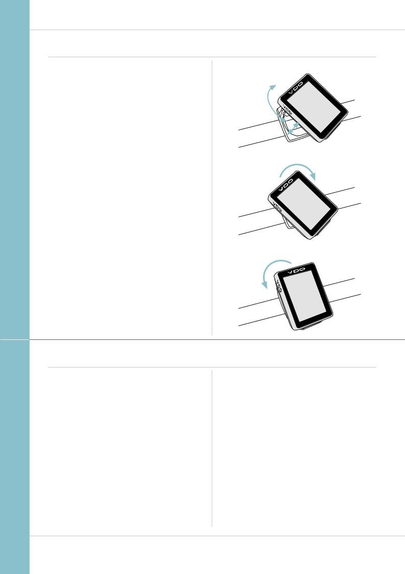
Inserting the computer into the bracket
The VDO twist-click system securely connects the computer to the handlebar bracket.
How to insert the computer:
STEP 1
Place the computer into the bracket in a 10 o’clock position.
STEP 2
Rotate the computer to the right into the 12 o’clock position and click it into the bracket system. A noticeable resistance must be overcome to move it into place.
STEP 3
To remove the computer, rotate it to the left (without pushing or pulling).
Memory aid: Rigid to the Right, Loose to the Left
LOCK
UNLOCK
1. LOCK 2. CLICK
2. UNLOCK
Function testing
Once the sensor has been attached, check that it functions correctly.
How to test the transmitter:
–Insert the computer into the bracket.
–Lift and spin the front wheel.
–A speed should now be displayed on the computer.
If no speed is displayed, there can be several reasons for this. The possible reasons are described in the “Troubleshooting” section.
7
 Loading...