

Vanguard DMOM-100, DMOM-200 s2 User Manual
OPERATING INSTRUCTIONS
for the
DMOM-100 Series 2
DMOM-200 Series 2
10-100/200 Amperes True DC
Digital Micro-Ohm Meters
Vanguard Instruments Company
1520 S. Hellman Ave.
Ontario, California 91761
TEL: (909) 923-9390 January 2009
FAX: (909) 923-9391 Rev. 2

DMOM-100/200 Series 2 Operating Procedures
SAFETY SUMMARY
NOTICE
This manual applies to Models DMOM-100, and DMOM-200 Series 2. The operating
procedures are virtually the same for all models. Any differences are clearly described in the
step-by-step procedures.
FOLLOW EXACT OPERATING PROCEDURES
Any deviation from the procedures described in this operator’s manual may create one or more
safety hazards, damage the DMOM, or cause errors in the test results. Vanguard Instruments Co.,
Inc. assumes no liability for unsafe or improper use of the DMOM.
The following safety precautions must be observed during all phases of test set-up, test hookups,
testing, and test-lead disconnects.
SAFETY WARNINGS AND CAUTIONS
This device shall be used only by trained operators.
All circuit breakers under test shall be off line and fully isolated.
DO NOT MODIFY TEST EQUIPMENT
Because of the risk of introducing unknown hazards, do not install substitute parts or perform
any unauthorized modification to any Model DMOM Test unit. To ensure that all designed
safety features are maintained, it is recommended that repairs be performed only by Vanguard
Instruments Co. factory personnel or by an authorized repair service. Unauthorized modifications
can cause serious safety hazards and will nullify the manufacturer's warranty.
2 Rev 2, 2009

DMOM-100/200 Series 2 Operating Procedures
Table of Contents
SAFETY SUMMARY.................................................................................................................... 2
1.0 INTRODUCTION .............................................................................................................. 6
1.1 Applicability ................................................................................................................... 6
1.2 General Description........................................................................................................6
1.3 Functional Description.................................................................................................... 6
1.4 Furnished Test Accessories............................................................................................. 6
1.5 Optional Accessories ...................................................................................................... 7
2.0 DMOM SPECIFICATIONS............................................................................................. 10
2.1 DMOM-100 Series 2 Specifications............................................................................. 10
2.2 DMOM-200 Series 2 Specifications............................................................................. 11
3.0 CONTROL AND DISPLAY............................................................................................ 12
3.1 DMOM-100 Series 2 Front Panel................................................................................. 12
3.2 DMOM-200 Series 2 Front Panel................................................................................. 14
4.0 DMOM IMPORTANT FEATURES................................................................................ 16
4.1 Operating Voltages ....................................................................................................... 16
4.2 DMOM Serial Interface................................................................................................ 16
4.3 DMOM LCD Contrast Adjustment .............................................................................. 16
4.4 DMOM Paper Advance or Retract ............................................................................... 16
5.0 DMOM PRINTER PAPER .............................................................................................. 16
6.0 CABLE CONNECTION .................................................................................................. 17
7.0 OPERATING PROCEDURES......................................................................................... 19
7.1 Step-by-Step Procedures............................................................................................... 19
7.2 Precautions.................................................................................................................... 19
7.3 Preparations................................................................................................................... 19
7.4 Operating Overview...................................................................................................... 19
7.5 Entering Alphanumeric Characters............................................................................... 20
7.6 Running a Normal Test Procedure................................................................................ 22
7.7 Running an Automatic Test Procedure......................................................................... 26
7.8 Entering Test Record ID............................................................................................... 29
7.9 Reviewing a Record...................................................................................................... 31
7.10 Restoring a Record........................................................................................................ 33
7.11 Printing the Test Record Directory............................................................................... 35
7.12 Erasing Test Records .................................................................................................... 37
7.13 Computer Interface Mode............................................................................................. 38
7.14 Calibration Check ......................................................................................................... 39
APPENDIX A............................................................................................................................... 41
3 Rev 2, 2009

DMOM-100/200 Series 2 Operating Procedures
Table of Figures
Figure 1.0 Combined Current and Sense Leads....................................................................... 7
Figure 2.0 DMOM-100/200 Sensing cable.............................................................................. 7
Figure 3.0 Hand Spike Sense Leads......................................................................................... 8
Figure 4.0 Current Cable.......................................................................................................... 8
Figure 5.0 C-Clamp Cable........................................................................................................9
Figure 6.0 DMOM-100 Series 2 Control-Panel Controls and Display.................................. 12
Figure 7.0 DMOM-200 Series 2 Control-Panel Controls and Display.................................. 14
Figure 8.0 DMOM-100/200 Connection Diagram 1 (Separate Leads).................................. 17
Figure 9.0 DMOM-100/200 Connection Diagram 2 (Combined Leads)............................... 17
Figure 10.0 DMOM-100/200 Connection Diagram 3 (Separate Leads).................................. 18
Figure 11.0 DMOM-100/200 Connection Diagram 4 (Combined Leads)............................... 18
Figure 12.0 The START Menu ................................................................................................ 19
Figure 13.0 The SETUP Menu................................................................................................. 20
Figure 14.0 Step-by Step Procedures for DMOM-100/200..................................................... 21
Figure 15.0 Typical DMOM-100/200 Test Report.................................................................. 25
Figure 16.0 Typical Test Directory Printout............................................................................ 36
Figure 17.0 Calibration Connection (Separated Leads)........................................................... 40
Figure 18.0 Calibration Connection (Combined Leads).......................................................... 40
4 Rev 2, 2009

DMOM-100/200 Series 2 Operating Procedures
List of Tables
Table 1.0 DMOM-100 Series 2 Specifications......................................................................... 10
Table 2.0 DMOM-200 Series 2 Specifications......................................................................... 11
Table 3.0 Functional Description of DMOM-100 Series 2 Controls and Display ................... 13
Table 4.0 Functional Description of DMOM-200 Series 2 Controls and Display ................... 15
Table 5.0 Run Test Procedure (Measure an Unknown Resistance).......................................... 22
Table 6.0 Run Automatic Test Procedure (Measure an Unknown Resistance)........................ 26
Table 7.0 Enter Record ID Procedure (Company, Site, and Equipment Identification)
....................... 29
Table 8.0 Review Record Procedure.........................................................................................31
Table 9.0 Restore Record Procedures....................................................................................... 33
Table 10.0 Print Test Record Directory Procedures............................................................... 35
Table 11.0 Erase Test Record Procedure................................................................................ 37
Table 12.0 Computer Control Mode....................................................................................... 38
Table 13.0 Calibration Check Procedure................................................................................39
5 Rev 2, 2009

DMOM-100/200 Series 2 Operating Procedures
1.0 INTRODUCTION
1.1 Applicability
This manual applies to the Model DMOM-100 S2™ and Model DMOM-200 S2™ (hereafter,
DMOM), made by Vanguard Instruments Company, Inc.
1.2 General Description
The DMOM-100/200 Series 2 are the third generation micro-ohmmeters made by Vanguard
Instruments Company. The DMOM-100/200 features microprocessor-controlled highly accurate
measuring of very low resistances, ranging from 1 micro-ohm to 300 milli-ohms. The DMOM is
field-portable, rugged, and easily operated by first-time users with a minimum of training. It
features a 16-key push button pad for entering test parameters and control functions and a 4-line
by 20-character LCD alphanumeric readout for displaying control-option menus, measured
resistance values, and related identifying data. The DMOM has a built-in thermal printer, which
prints test data on 2.5-inch-wide thermal sensitive paper. The operation requires little more than
connecting test leads to an unknown resistance and selecting the desired functions and options.
Operators select the test current (10 to 100 amperes for DMOM-100 or 10 to 200 amperes for
DMOM-200) and test time (5 seconds to 2 minutes). Measured resistance data is displayed and
can be printed on the thermal printer. The measured resistance data can also be stored (up to 63
records of 96 readings each) in FLASH EEPROM memory. Operators can recall the stored
resistance measurements and related data at a later time for review and printing.
1.3 Functional Description
The DMOM’s operation is based on the electrical relationships described by Ohm’s law: R=V/I,
where I is a known current and V is the dc voltage measured across the unknown resistance
(typically, a circuit breaker’s contacts). Since the current (user selected) through the unknown
resistance is known and the voltage across the unknown resistance is read by a precision
voltmeter, the unknown resistance can be calculated using Ohm’s law.
The DMOM’s test voltage is supplied by a true 5Vdc power supply. The true DC test current is
selectable from 10 to 100 amperes for the DMOM-100 and from 10 to 200 amperes for the
DMOM-200. Test current is automatically ramped up and down slowly. This current ramp rate is
programmable from 5 seconds to 30 seconds.
Voltmeter test leads run separately from the current-bearing test leads to the resistive load to
eliminate any I•R voltage drop error in the current cables. These DMOM features make very
precise micro-ohm measurements possible without having to calculate co mpensations for
current-lead resistance errors.
1.4 Furnished Test Accessories
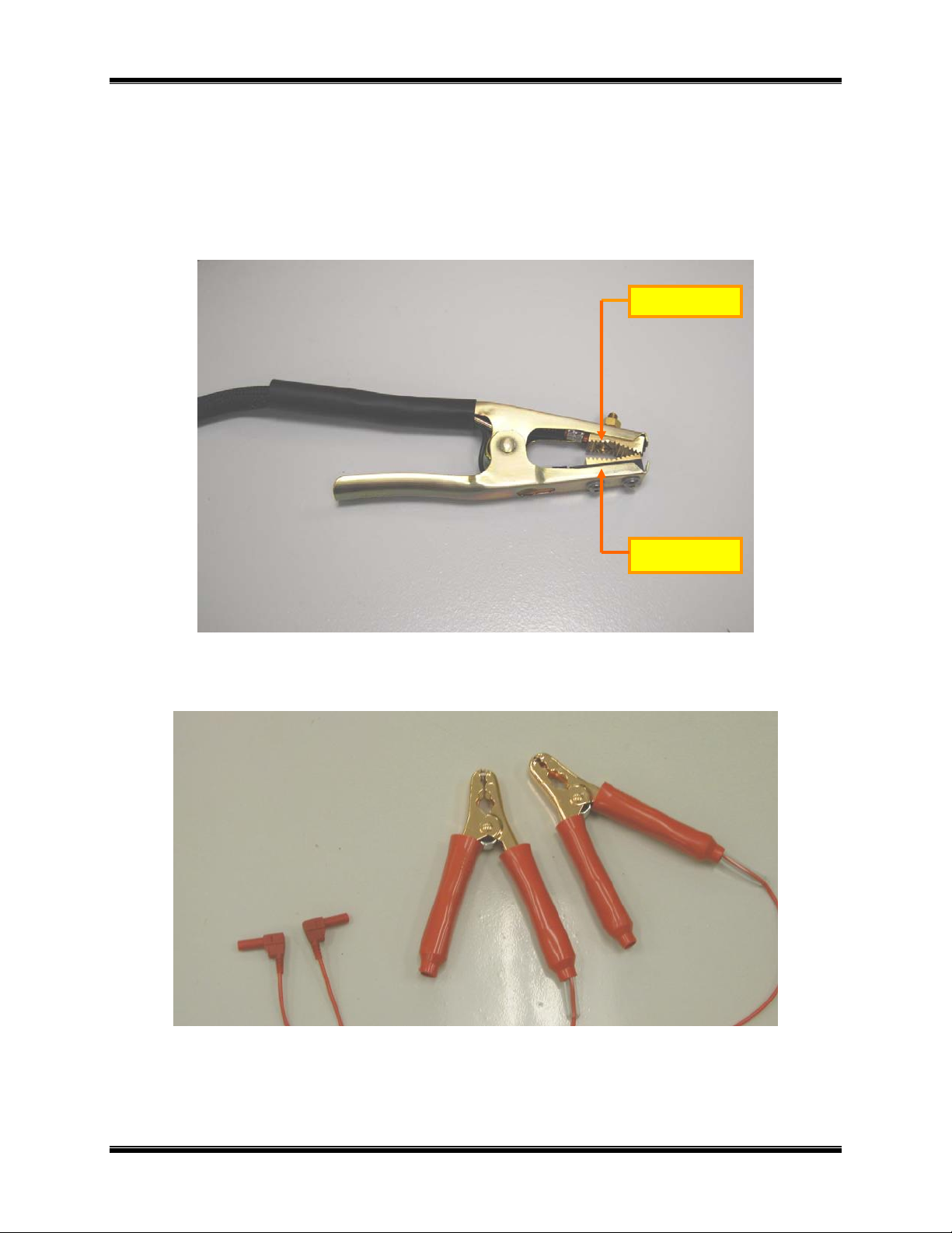
The DMOM is supplied with two 30-foot test cables with heavy-duty alligator clamps. Both the
current (#1 AWG) and sense leads are combined into one cable (Figure 1.0). A ground cable and
a power cord are also included with each DMOM.
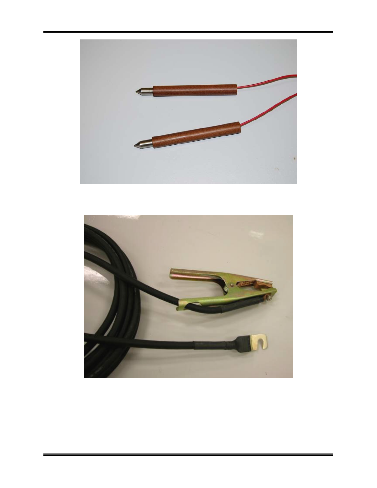
Users can choose to have the current and sense leads separated as shown in Figure 2.0 and Figure
4.0. Optional hand spike sense leads are also available as shown in Figure 3.0.
6 Rev 2, 2009
DMOM-100/200 Series 2 Operating Procedures
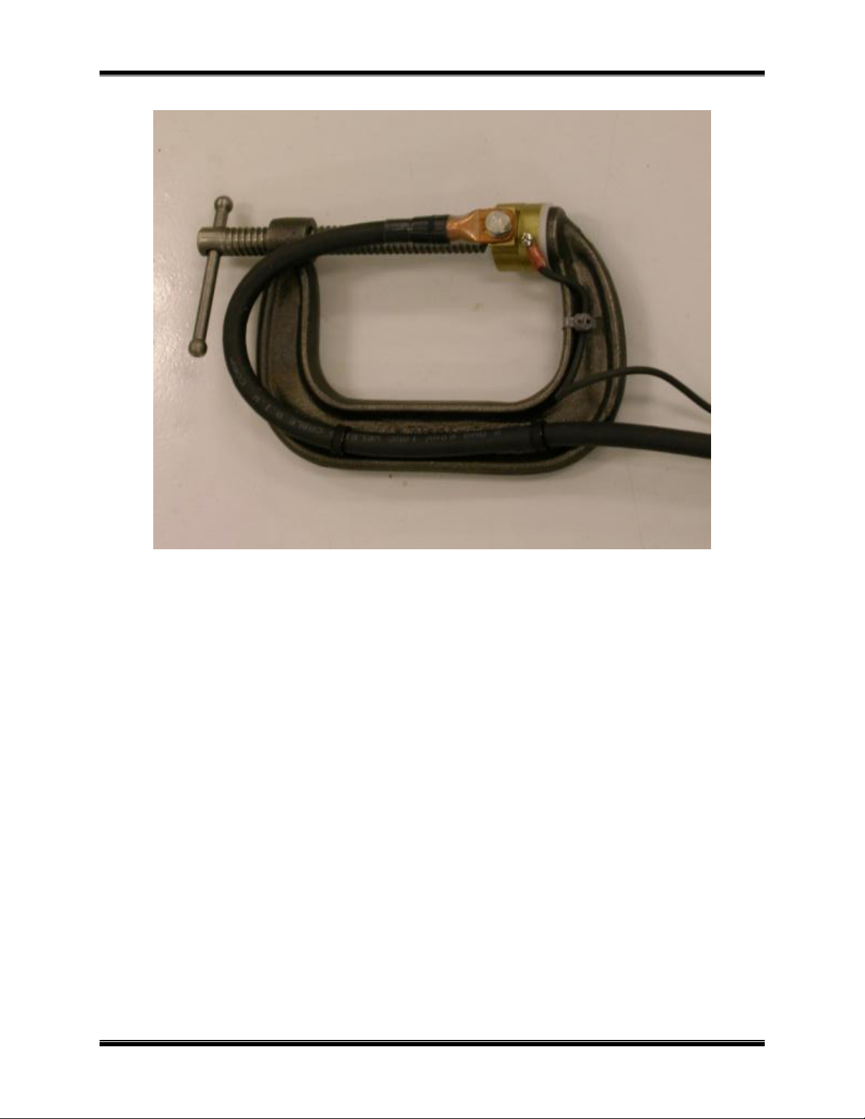
1.5 Optional Accessor ies
1. Heavy-duty welding-type C-clamps (Figure 5.0) are available as optional accessories. These
C-clamps allow test lead connections to a wide variety of bushing sizes, bus bars, and
conductors that require low-resistance test-lead contacts.
2. Light weight (#4 AWG) cables are also available upon request.
3. Custom cable lengths are available upon request.
Current Jaw
Voltage Jaw
Figure 1.0 Combined Current and Sense Leads
Figure 2.0 DMOM-100/200 Sensing cable
7 Rev 2, 2009
DMOM-100/200 Series 2 Operating Procedures
Figure 3.0 Hand Spike Sense Leads
Figure 4.0 Current Cable
8 Rev 2, 2009
DMOM-100/200 Series 2 Operating Procedures
Figure 5.0 C-Clamp Cable
9 Rev 2, 2009

DMOM-100/200 Series 2 Operating Procedures
2.0 DMOM SPECIFICATIONS
2.1 DMOM-100 Series 2 Specifications
DMOM-100 specifications and leading particulars are listed in Table 1.0.
Table 1.0 DMOM-100 Series 2 Specifications
MODEL...................... DMOM-100 Series 2
TYPE............................. Special-Purpose Test Equipment, Portable, Low Resistance-Ohmmeter
CONFIGURATION...... Third-generation (improved design, superseding original model)
SIZE (inches).............. 16.8” Wide by 12.6” High by 12” Deep (42.7 Cm x 32 Cm x 30.5 Cm)
WEIGHT........................ 28 lbs. (12.70 Kg)
OPERATING ............... 100-240Vac, 8A, 50/60 Hz, with built in 10A circuit breaker
VOLTAGE
TEST CURRENT
RANGE......................... 10 Amperes to 100 Amperes, selectable in 1 ampere steps
RESISTANCE
RANGE......................... 1 micro-ohm to 300 milli-ohms
ACCURACY................. ± 1 % of Reading, ± 1 Count
MEMORY...................... 63 records of 96 readings each
DISPLAY...................... Backlit LCD, 4-lines high by 20 characters wide
CONTROL.................... Keypad: 10 number keys and 6-function keys
PRINTER...................... Thermal printer, 2.5-inch wide thermal paper
POWER ........................ 8 amps, 100-240Vac, 50/60 Hz, with built in 10A circuit breaker
UNIT PROTECTION... Thermal-overload sensor and cutoff
INTERFACE................. RS-232C Connector Port for PC Interface
ENVIRONMENT..........Operating: 0°C to 55°C; Storage: -40°C to 65°C
FURNISHED ITEMS... One power cord, one ground cable, two 30-ft. test lead cables
EXPENDABLES ........ Paper, Thermal sensitive, 2.5-inch wide roll (VIC p/n TP3)
WARRANTY................ One-Year Parts & Labor (Post-Warranty Service Contracts Available)
DMOM-100 S2 SPECIFICATIONS ARE SUBJECT TO UPGRADES AND MAY BE CHANGED WITHOUT PRIOR NOTICE.
10 Rev 2, 2009

DMOM-100/200 Series 2 Operating Procedures
2.2 DMOM-200 Series 2 Specifications
DMOM-200 specifications and leading particulars are listed in Table 2.0.
Table 2.0 DMOM-200 Series 2 Specifications
MODEL...................... DMOM-200 Series 2
TYPE............................. Special-Purpose Test Equipment, Portable, Low Resistance-Ohmmeter
CONFIGURATION...... Third-generation (improved design, superseding original model)
SIZE (inches).............. 16.8 Wide by 12.6 High by 10.6 Deep (42.7 Cm x 32 Cm x 30.5 Cm)
WEIGHT........................ 33 pounds (14.97 Kg)
OPERATING ............... 100-240Vac, 8A, 50/60 Hz, with 10A circuit breaker
VOLTAGE
TEST CURRENT
RANGE......................... 10 Amperes to 200 Amperes, selectable in 1 ampere steps
RESISTANCE
RANGE......................... 1 micro-ohm to 300 milli-ohms
ACCURACY................. ± 1 % of Reading, ± 1 Count
MEMORY...................... 63 records of 96 readings each
DISPLAY...................... Backlit LCD, 4-lines high by 20 characters wide
CONTROL.................... Keypad: 10 number keys and 6-function keys
PRINTER...................... Thermal printer, 2.5-inch wide thermal paper
POWER ........................ 8 amps, 100-240Vac, 50/60 Hz, with built in 10A circuit breaker
UNIT PROTECTION... Thermal-overload sensor and cutoff
INTERFACE................. RS-232C Connector Port for PC Interface
ENVIRONMENT..........Operating: 0°C to 55°C; Storage: -40°C to 65°C
FURNISHED ITEMS... One power cord, one ground cable, two 30-ft. test lead cables
EXPENDABLES ........ Paper, Thermal sensitive, 2.5-inch wide roll (VIC p/n TP3)
WARRANTY................ One-Year Parts & Labor (Post-Warranty Service Contracts Available)
DMOM-200 S2 SPECIFICATIONS ARE SUBJECT TO UPGRADES AND MAY BE CHANGED WITHOUT PRIOR NOTICE.
11 Rev 2, 2009
DMOM-100/200 Series 2 Operating Procedures
3.0 CONTROL AND DISPLAY
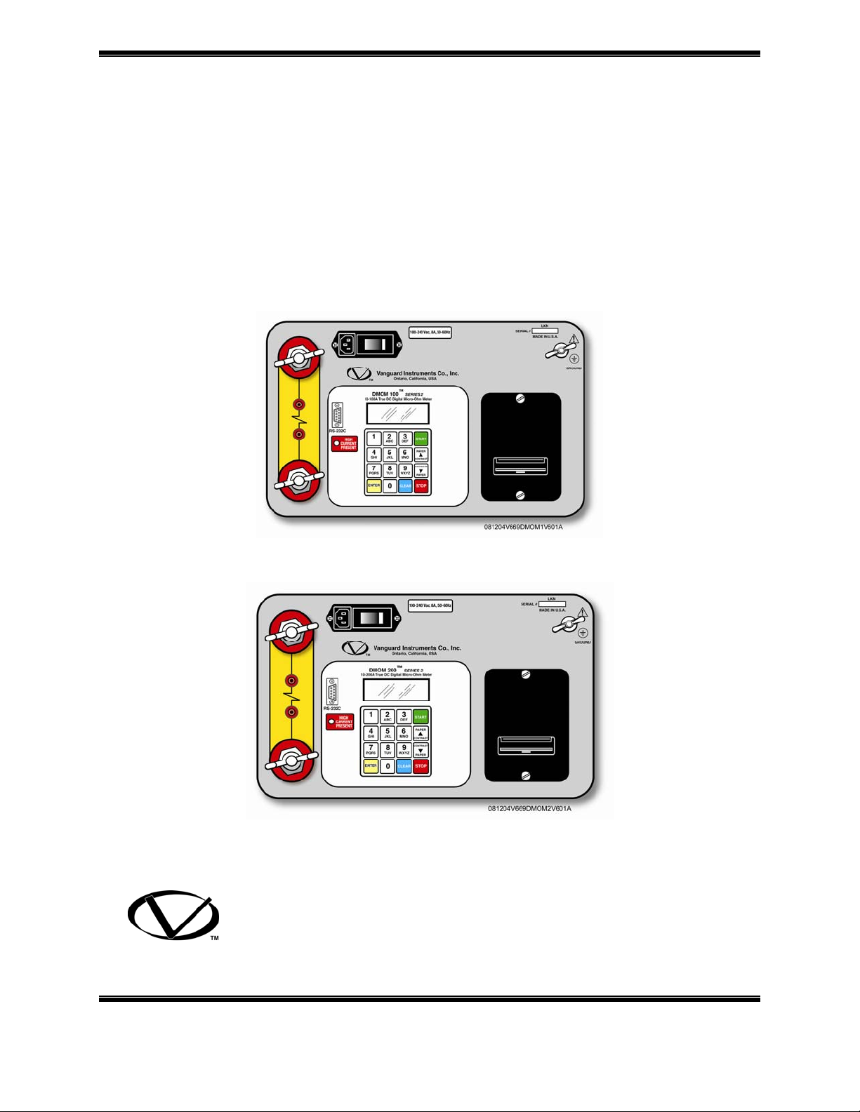
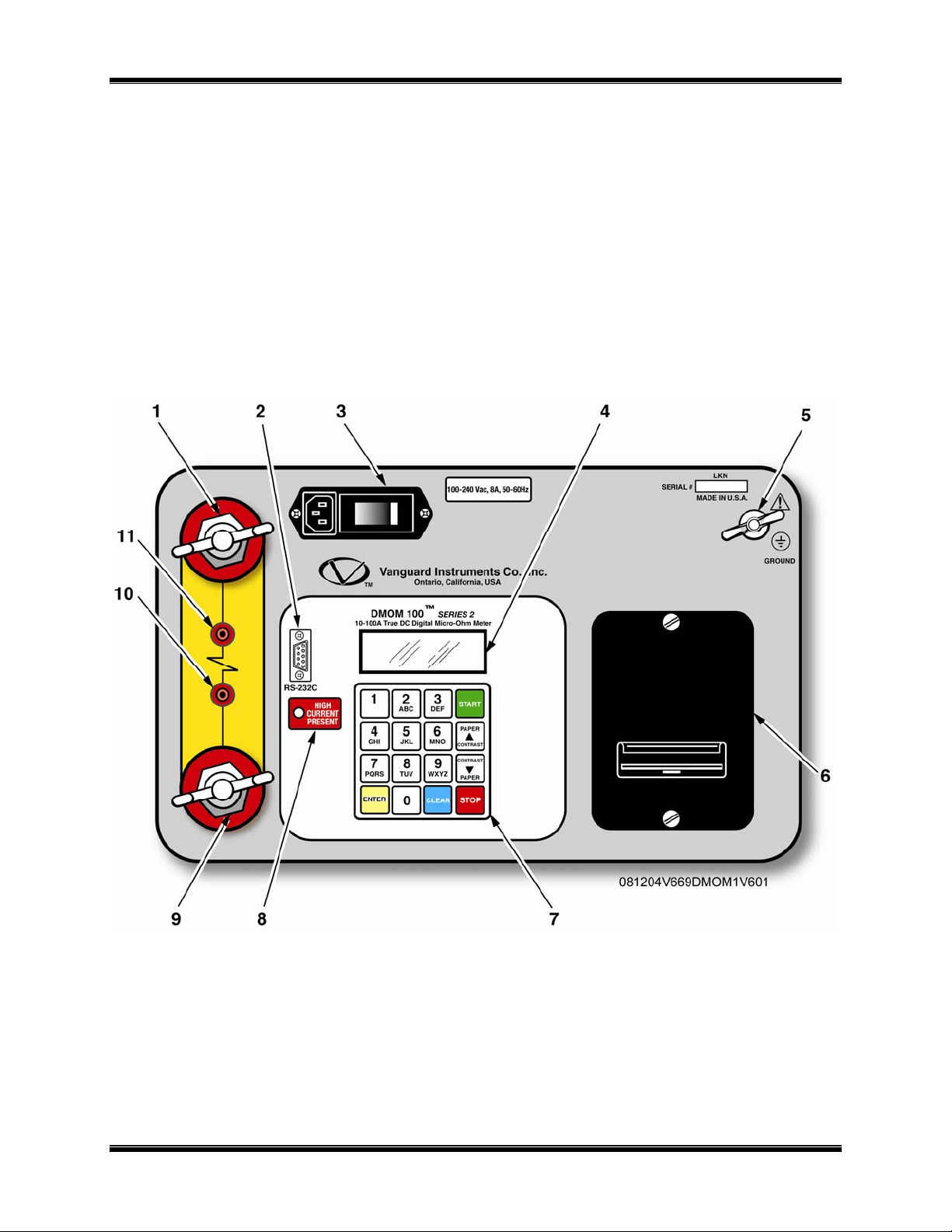
3.1 DMOM-100 Series 2 Front Panel
The DMOM-100 Series 2 controls and displays are shown in Figure 6.0, the control-panel
illustration below. Pointing leader lines reference each item with an index number. Each index
number is cross-referenced to a functional description in Table 3.0, which describes the function
and purpose of each item on the control panel. Although the purpose of these controls and the
display may seem obvious and intuitive, users should become familiar with them before
attempting to use the DMOM-100 Series 2. First-time users should also review and become
familiar with the Safety Summary on the front page.
Figure 6.0 DMOM-100 Series 2 Control-Panel Controls and Display
12 Rev 2, 2009

DMOM-100/200 Series 2 Operating Procedures
Table 3.0 Functional Description of DMOM-100 Series 2 Controls and Display
Figure 1
Index #
1 & 9
2
Adjacent Panel Marking
(Wing Nut)
RS-232C
Functional Description
Current lead connectors
RS-232C interface port; 9-pin connector;
female DB type. The data rate is set to 19,200
baud, 1 start bit, 8 data bits, and no parity bit;
PIN
................SIGNAL
2 Rx
3 Tx
5 Signal Gnd
This serial port is for factory calibration,
firmware updates, and interfacing with the
software program supplied with each unit.
Input power connector with third-wire safety
ground and built-in 10A circuit breaker.
LCD; 4-line by 20-character; back-lighted;
displays menus of selections, operator entries,
and test-measurement results.
DMOM-100 Series 2 ground stud. Connect
ground stud to substation ground using the
provided cable.
Built-in thermal printer, prints test result data
on 2.5-inch-wide thermal paper.
Operating key-pad controls, 10 alphanumeric
keys and 6 function keys (i.e., START,
3
4
5
6
7
100-240 Vac, 8A, 50- 60 Hz
No marking
GROUND
(Wing Nut)
No marking
No marking
STOP, CLEAR, ENTER, &
CONTRAST/PAPER positioning ∧ & ∨).
8
10 & 11
HIGH CURRENT
PRESENT
(Resistor Symbol)
LED indicator, red; Lights when high-testcurrent is going through the test leads.
Voltage-sensing connector jacks (red).
13 Rev 2, 2009
 Loading...