


Installation and User Guide
VADDIO™ WALLVIEW™ HD-22 & HD-30 DVI/HDMI SR CAMERA SYSTEMS
PowerVIEW™ Series High Definition PTZ Cameras featuring the Quick-Connect™ DVI/HDMI SR Interface
WallVIEW HD-22 DVI/HDMI SR - High Definition PTZ Camera System (22X Optical Zoom)
Model Number 999-6966-000 (North America)
Model Number 999-6966-001 (International)
WallVIEW HD-30 DVI/HDMI SR - High Definition PTZ Camera System (30X Optical Zoom)
Model Number 999-6976-000 (North America)
Model Number 999-6976-001 (International)
Quick-Connect DVI/HDMI SR Interface
PN: 998-1105-018
© 2013 Vaddio - All Rights Reserved. WallVIEW HD-22 & HD-30 DVI/HDMI SR Camera Systems - Document Number 342-0644 Rev A

WallVIEW HD-22 and HD-30 SR Systems
Inside Front Cover - Blank
WallVIEW HD-22 and HD-30 DVI/HDMI SR Cameras Systems - Document Number 342-0644 Rev A |
Page 2 of 24 |

WallVIEW HD-22 and HD-30 SR Systems |
|
TABLE OF CONTENTS |
|
Overview.................................................................................................................................................................... |
4 |
Unpacking.................................................................................................................................................................. |
5 |
Camera Front View with Feature Call-outs............................................................................................................ |
6 |
Image: WallVIEW HD-22/30 SR Camera System............................................................................................. |
6 |
Rear Panel Connections with Feature Call-outs.................................................................................................... |
7 |
Image: WallVIEW HD-22/30 SR Camera System............................................................................................. |
7 |
First Time Set-up with the WallVIEW HD-22 or HD-30 DVI/HDMI SR System......................................................... |
8 |
Image: PowerVIEW HD-22/30 Rear Panel Connections .................................................................................. |
8 |
Drawing: Dip Switch and Resolution Label on the Bottom of the HD-22/30 ...................................................... |
8 |
Quick-Connect DVI/HDMI SR Interface..................................................................................................................... |
9 |
Image: Rear Panel Connectors and Features................................................................................................... |
9 |
Image: Quick-Connect DVI/HDMI SR Interface Front Panel ............................................................................ |
9 |
Installation Procedures ............................................................................................................................................ |
10 |
Before Installing: .................................................................................................................................................. |
10 |
Installation Basics: ............................................................................................................................................... |
10 |
General Installation Instructions for the CONCEAL Wall Mounting System:....................................................... |
10 |
Image: Basic Connectivity Example of the HD-22 or HD-30........................................................................... |
12 |
Daisy Chain Configurations ..................................................................................................................................... |
13 |
Compliance and CE Declaration of Conformity - PowerVIEW HD-22 and HD30 ................................................... |
14 |
Compliance and CE Declaration of Conformity - Quick-Connect DVI/HDMI SR Interface ..................................... |
15 |
Warranty Information ............................................................................................................................................... |
16 |
General Specifications............................................................................................................................................. |
17 |
Appendix 1: Pin-Outs for the HD-22/30 Camera ................................................................................................... |
18 |
Drawing: PowerVIEW HD-22/30 Camera Dimensions.................................................................................... |
19 |
Communication Specification .................................................................................................................................. |
20 |
HD-22/30 Command List (1/2) ......................................................................................................................... |
20 |
HD-22/30 Command List (2/2) ......................................................................................................................... |
21 |
HD-22/30 Inquiry List (1/1) ............................................................................................................................... |
22 |
WallVIEW HD-22 and HD-30 DVI/HDMI SR Cameras Systems - Document Number 342-0644 Rev A |
Page 3 of 24 |

WallVIEW HD-22 and HD-30 SR Systems
OVERVIEW
The remarkable Vaddio PowerVIEW HD-22 and HD-30 high definition PTZ cameras are available in the super-versatile Vaddio WallVIEW DVI/HDMI SR (short range) system packages. The WallVIEW HD-22 DVI/HDMI SR and the WallVIEW HD-30 DVI/HDMI SR feature 22X and 30X power zoom optics respectively. These cameras use the latest Maicovicon MOS, 1/2.8-Type, progressive scan image sensors, which provide for better light sensitivity, increased noise reduction and lower power consumption than cameras with either CCD or CMOS image sensors. This advanced MOS image sensor captures realistic textures, vivid colors and delicate gradations that are comparable to 3-chip camera performance.
Both the HD-22 and the HD-30 provide matchless low-light capabilities with a minimum illumination rating of an amazing 0.4 lux (color) and 0.04 lux (B/W). Equipped with a 2.2 megapixel MOS sensor, the cameras deliver native 1080p/60 high definition video resolution and superior color reproduction for use in any professional A/V presentation, videoconferencing, House of Worship, education, live event and industrial applications.
Image: PowerVIEW HD-22 or HD-30 PTZ Camera (above) and the Quick-Connect DVI/HDMI SR Interface (below)
The HD-22 has a powerful 22X multi-element glass zoom lens (f=4.3mm to 94.6mm) and works exceptionally in large rooms. However, the premium optics also provides a super-wide horizontal field of view of 65.2º, which works very well in small room video applications. The HD-30, as one can imagine, has a robust 30X optical power zoom lens that enables the capture of brilliant and detailed video images even in the largest rooms.
The cameras output multi-format HD video in both analog component (YPbPr), HDMI and differential formats in HD resolutions of 1080p/59.94, 1080p/50 1080p/29.97 1080p/25, 1080i/59.94, 1080i/50, 720p/59.94, 720p/50 and progressive SD resolutions of 480p/59.97 and 576p/50. Both cameras are offered in WallVIEW DVI/HDMI SR packages with the Quick-Connect DVI/HDMI SR Interface that uses HSDS™ for distribution of video, power and control over Cat-5 cable up to 100’ (30.48m) and are capable of outputting analog component YPbPr and HDMI concurrently from the Quick-Connect interface. The WallVIEW HD-22 and HD-30 DVI/HDMI SR camera systems represent an exceptional value and are superb performers for even the most demanding video applications.
Intended Use:
Before operating the device, please read the entire manual thoroughly. The system was designed, built and tested for use indoors with the power supply provided. The use of a power supply other than the one provided or outdoor operation hasn’t been tested and may damage the device and/or create an unsafe operating condition.
Important Safeguards:
Read and understand all instructions before using. Do not operate any device if it has been dropped or damaged. In this case, a Vaddio technician must examine the product before operating. To reduce the risk of electric shock, do not immerse in water or other liquids and avoid extremely humid conditions.
Use only the power supply provided with the system. Use of any unauthorized power supply will void any and all warranties.
Please do not use “pass-thru” type RJ-45 connectors. These pass-thru type connectors do not work well for professional installations and can be the cause of intermittent connections which can result in the RS-232 control line failing and locking up, and/or compromising the HSDS (high speed differential) signals. For best results please use standard RJ-45 connectors and test all cables for proper pin-outs prior to use and connection to Vaddio product.
Save These Instructions:
The information contained in this manual will help you install and operate your product. If these instructions are misplaced, Vaddio keeps copies of Specifications, Installation and User Guides and most pertinent product drawings for the Vaddio product line on the Vaddio website. These documents can be downloaded from www.vaddio.com free of charge.
WallVIEW HD-22 and HD-30 DVI/HDMI SR Cameras Systems - Document Number 342-0644 Rev A |
Page 4 of 24 |

WallVIEW HD-22 and HD-30 SR Systems
UNPACKING
Carefully remove the product and all of the included parts from the packaging. Identify the following parts for each camera:
WallVIEW HD-22 SR Camera System (North America):
Part Number: 999-6965-000
One (1) PowerVIEW HD-22 HD PTZ Camera (998-6960-000)
One (1) Vaddio IR Remote Commander
One (1) Quick-Connect DVI/HDMI SR Interface
One (1) 3-Position Phoenix-type Connector for IR Forwarding
One (1) 24 VDC, 2.0 A Power Supply with Power Cord for North America
One (1) CONCEAL Wall Mount with Mounting Hardware
One (1) EZCamera™ Control Adapter (RJ-45-F to DB-9-F)
Documentation
WallVIEW HD-22 SR Camera System (International):
Part Number: 999-6965-001
One (1) PowerVIEW HD-22 HD PTZ Camera (998-6960-000)
One (1) Vaddio IR Remote Commander
One (1) Quick-Connect DVI/HDMI SR Interface
One (1) 3-Position Phoenix-type Connector for IR Forwarding
One (1) 24 VDC, 2.0 A Power Supply
One (1) Euro Power Cable
One (1) UK Power Cable
One (1) CONCEAL Wall Mount with Mounting Hardware
One (1) EZCamera Control Adapter (RJ-45 to DB-9)
Documentation
WallVIEW HD-30 SR Camera System (North America):
Part Number: 999-6975-000
One (1) PowerVIEW HD-30 HD PTZ Camera (998-6970-000)
One (1) Vaddio IR Remote Commander
One (1) Quick-Connect DVI/HDMI SR Interface
One (1) 3-Position Phoenix-type Connector for IR Forwarding
One (1) 24 VDC, 2.0 A Power Supply with Power Cord for North America
One (1) CONCEAL Wall Mount with Mounting Hardware
One (1) EZCamera Control Adapter (RJ-45-F to DB-9-F)
Documentation
WallVIEW HD-30 SR Camera System (International):
Part Number: 999-6975-001
One (1) PowerVIEW HD-30 HD PTZ Camera (998-6970-000)
One (1) Vaddio IR Remote Commander
One (1) Quick-Connect SR Interface
One (1) 3-Position Phoenix-type Connector for IR Forwarding
One (1) 24 VDC, 2.0 A Power Supply
One (1) Euro Power Cable
One (1) UK Power Cable
One (1) CONCEAL Wall Mount with Mounting Hardware
One (1) EZCamera Control Adapter (RJ-45 to DB-9)
Documentation
CONCEAL Mount includes:
Metal Bracket (black)
Bottom Cover
Rear Connector/Cable Cover
Mounting Hardware
WallVIEW HD-22 and HD-30 DVI/HDMI SR Cameras Systems - Document Number 342-0644 Rev A |
Page 5 of 24 |

WallVIEW HD-22 and HD-30 SR Systems
Camera Front View with Feature Call-outs
Image: WallVIEW HD-22/30 SR Camera System


1) Camera and Zoom Lens:
The 22X (HD-22) or 30X (HD-30) optical zoom lens is built around a (1/2.8 Type) high-speed MOS image sensor with a total of 2.2 megapixels for precise HD video image acquisition.
2) Red Tally Light:
A red tally light is illuminated when the camera receives a command from an external controller.
3) IR Sensors:
IR sensors are built into the front of the HD-22 and HD-30 to receive IR signals from the IR remote control supplied with the camera.
4) Blue Power Light:
A Vaddio blue power light is illuminated when the camera is turned on.
WallVIEW HD-22 and HD-30 DVI/HDMI SR Cameras Systems - Document Number 342-0644 Rev A |
Page 6 of 24 |
WallVIEW HD-22 and HD-30 SR Systems
Rear Panel Connections with Feature Call-outs
Image: WallVIEW HD-22/30 SR Camera System


5) RS-232 IN & IR Out:
The RS-232 port accepts modified VISCA protocol for camera control, as well as transmits IR signaling received by the IR receivers, which can be transmitted to third party remotes.
6) Dip Switch Settings:
Settings for IR remote, baud rate and image flip can be configured on these switches. See the Switch Settings page for additional information.
7) HD Video Select:
A rotary switch allows the user to choose the component HD output video resolution and format. See the Switch Settings page for additional information.
HD Resolution Note: When changing the resolution of the camera, the camera should be powercycled after the change.
8) 12 VDC Input:
Power input for the standard 12 VDC, 3.0 Amp power supply for the HD-22 and HD-30. The 12 VDC power supply is only used with the standalone cameras, but not with the WallVIEW systems).
9) HDMI Output:
The HDMI output feeds out HD digital video only (no copy protect or device communication is required). The HDMI output is optimized for high definition video signals.
10) YPbPr Output:
Component HD video (YPbPr) is output through the DE-15 connector. YPbPr and HDMI signals have simultaneous output. Limited SD resolutions are supported.
11) EZ Power HD Video Port:
This RJ-45 connector is used with the Quick-Connect SR type interfaces to supply power and return HSDS (differential) video from the camera. Please mark and test cables for voltage. prior to connection.
12) Slot for Optional Cards:
Optional slot cards can be plugged into the rear panel slot of the HD-22 and HD-30 cameras. The HD-SDI Slot Card is sold separately and the EZIM CCU Slot Card is available in the CCU system package.
WallVIEW HD-22 and HD-30 DVI/HDMI SR Cameras Systems - Document Number 342-0644 Rev A |
Page 7 of 24 |
WallVIEW HD-22 and HD-30 SR Systems
FIRST TIME SET-UP WITH THE WALLVIEW HD-22 OR HD-30 DVI/HDMI SR SYSTEM
The PowerVIEW HD-22 and HD-30 cameras in the WallVIEW Kit were designed to be very easy to use and operate. There is documentation at the back of this manual for pin-outs of the connectors.
Step 1: Using the HD VIDEO SELECT rotary switch and CAMERA SETTINGS dip switches on the back of the camera, set up the camera’s output resolution and functional preferences. There is a label on the bottom of the camera that identifies the choices.
Important Dip Switch Note: Setting all dip switches down and the first time set-up, loading the defaults may be a good idea.
cycling the camera will load the factory default camera settings. For
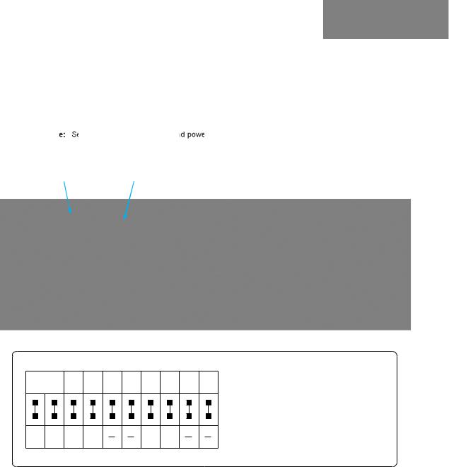
Image: PowerVIEW HD-22/30 Rear Panel Connections
HD Video Select Switch |
|
|
|
Camera Settings 10-Pos Dip Switch |
HD-22/30 Rear Panel |
|
|
|
|||
(Set HD resolution) |
|
|
|
(Set functional preferences) |
Drawing: Dip Switch and Resolution Label on the Bottom of the HD-22/30
DIP SWITCH SETTINGS
IR 1 |
IR |
9600 |
5 |
6 |
HDMI |
IMAGE |
9 |
10 |
|
OUT |
COLOR |
FLIP |
|||||||
1 & 2 UP |
bps |
OFF |
OFF |
OFF |
OFF |
||||
|
OFF |
|
|
|
YCbCr |
OFF |
|
|
|
|
|
|
|
|
|
|
|
|
|
All Down |
|
|
|
|
|
|
|
|
|
|
with Power |
|
|
|
|
|
|
|
|
|
|
Cycle for |
IR 2 |
IR 3 |
|
38400 |
|
|
sRGB |
|
|
|
Defaults |
ON |
ON |
ON |
bps |
|
|
ON |
|
|
|
|
1 |
2 |
3 |
4 |
5 |
6 |
7 |
8 |
9 |
10 |
|
|
|
|
|
|
|
|
|
|
|
VIDEO RESOLUTION SELECT
0 |
720p/59.94 |
8 |
576p/50 |
||||
1 |
1080i/59.94 |
9 |
|
|
|
||
|
|
|
|||||
2 |
1080p/59.94 |
A |
|
|
|
||
|
|
|
|||||
3 |
|
|
|
B |
|
|
|
|
|
|
|
|
|
||
4 |
720p/50 |
C |
|
|
|
||
|
|
|
|||||
5 |
1080i/50 |
D |
|
|
|
||
|
|
|
|||||
6 |
1080p/50 |
E |
1080p/29.97 |
||||
7 |
480p/59.94 |
F |
1080p/25 |
||||
Setting the Switches:
1)Set the desired and available HD output resolution for the camera with the Rotary Switch.
2)Set the IR control frequency of the camera if it is to respond to the IR remote control.
3)If using the IR forwarding features with a 3rd party codec remote, set the IR OUT switch to ON (SW3).
4)Set the Baud Rate dip switch (SW4) to 9600bps for most applications. Default is 9600 bps for Cat-5 systems.
5)To set the HDMI or DVI color space, use dip switch 7 (SW7).
6)If inverting the camera, turn the IMAGE FLIP ON (SW8).
7)All dip switches DOWN with a power cycle loads the default camera settings. Return dips to desired operating position.
Dip Switch Settings Explained:
IR 1, 2 and 3 (SW 1 &2): A single IR remote has the capability of operating up to three different PTZ cameras in a room. Use these selector dip switches and the selector buttons at the top of the IR remote to select the frequency.
IR OUT on/off (SW3): The IR output is sent out on the RS-232 RJ-45 jack on the back of the camera. Turning on the IR output will allow IR signals to be transmitted over the Cat-5 cable to the head end. When using RS-232 control or Vaddio CCU controllers (also via RS-232), turn the IR OUT to OFF (up).
Baud Rate (SW4): The options for baud rate are either 9600 or 38,400 bps. The 9600 bps works best with Cat-5..
HDMI Color or sRGB Color space (SW7): Default is YCbCr. Use sRGB color space with older DVI-D 1.0 monitors only. The YCbCr color space is best for HDMI digital video.
Image Flip (SW8): To invert the HD-20, turn the IMAGE FLIP ON (switch down).
Dip Switches 5, 6, 9 and 10: Not used for operation, please leave these dip switches up or in the OFF position.
WallVIEW HD-22 and HD-30 DVI/HDMI SR Cameras Systems - Document Number 342-0644 Rev A |
Page 8 of 24 |
 Loading...