


Installation and User Guide
Camera and Electronic Products for Integrators
PRODUCTIONVIEW™ SUPER JOYSTICK
Integration Joystick with Six Discrete Camera Control Ports, On-board Camera Presets, LCD Preview Monitor and External Control Capability
©2007 Vaddio - All Rights Reserved. ProductionVIEW Super Joystick - Document 341-565 Rev B.
ProductionVIEW Super Joystick
Overview:
The Vaddio™ |
ProductionVIEW |
Super |
|
||||
Joystick is a unique integration joystick |
|
||||||
contoller |
that |
is |
based |
on |
the |
|
|
ProductionVIEW |
series |
of |
camera |
|
|||
controllers. The Super Joystick has six |
|
||||||
individual RS-232C camera control ports for |
|
||||||
direct control of PTZ cameras which |
|
||||||
eliminates the need for daisy chain control |
|
||||||
cabling. The camera control ports are on |
|
||||||
RJ-45 connectors which easily connect to |
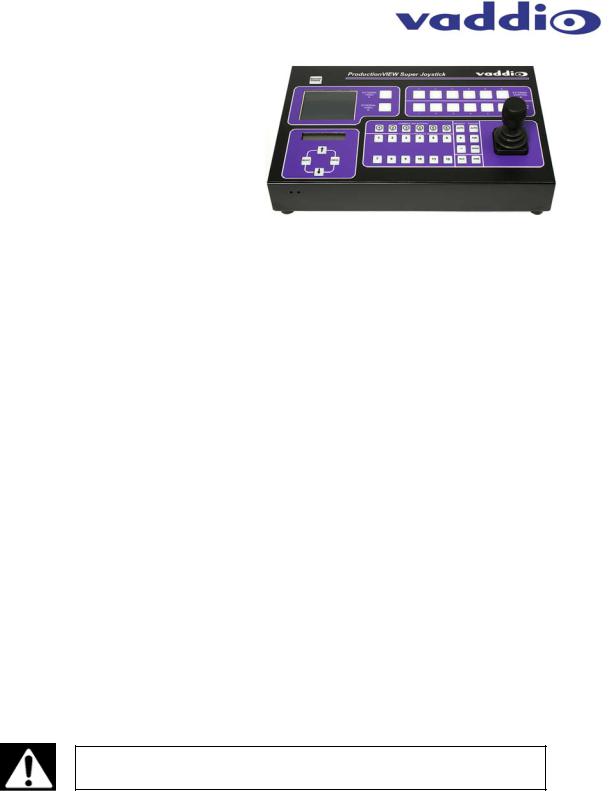
Figure 1: ProductionVIEW Super Joystick |
||||||
the Vaddio EZCamera™ cabling packages |
|||||||
using a Cat. 5 wiring standard.
Each of the six camera control ports will auto-configure based on the robotic PTZ camera system connected to that port upon boot up. Whether it is a Vaddio, Sony® or Canon® PTZ camera system the ProductionVIEW Super Joystick senses the cameras and provides for seamless control of the camera functions. Each of the six cameras attached has been supplied with 12 internally stored camera presets effectively removing the internal preset limitations of the camera. Each of the six cameras attached can also be adjusted individually for the operating environment with adjustments for auto/manual focus, auto/manual brightness, backlight compensation and one push automatic white balance.
The ProductionVIEW Super Joystick has two rows of six external control switches which can be used in a variety of ways. These switches are tied to trigger outputs and can be used to control external video switchers with contact closures or tally lights for studio applications. The Super Joystick also has provision for external control of select HD switchers/mixers with built-in RS-232 codes in the system menu. And like the ProductionVIEW FX, the ProductionVIEW Super Joystick console has a 4” LCD preview monitor is built-in. Overall, the ProductionVIEW Super Joystick is a unique and advanced camera controller that is unmatched in today’s market for functionality, convenience and value.
Intended Use:
Before operating the Vaddio ProductionVIEW Super Joystick, please read the entire manual thoroughly. The system was designed, built and tested for use indoors, and with the provided power supply and cabling. The use of a power supply other than the one provided or outdoor operation has not been tested and could damage the camera and/or create a potentially unsafe operating condition.
Save These Instructions:
The information contained in this manual will help you install and operate your Vaddio ProductionVIEW Super Joystick. If these instructions are misplaced, Vaddio keeps copies of Specifications, Installation and User Guides and most pertinent product drawings for the Vaddio product line on the Vaddio website. These documents can be downloaded from www.vaddio.com free of charge.
Important Safeguards:
Read and understand all instructions before using. Do not operate any device if it has been dropped or damaged. In this case, a Vaddio technician must examine the product before operating. To reduce the risk of electric shock, do not immerse in water or other liquids and avoid extremely humid conditions.
Use only the power supply provided with the ProductionVIEW system.
Use of any unauthorized power supply will void any and all warranties.
UNPACKING:
Carefully unpack and identify the following parts from the packaging.
•One (1) ProductionVIEW Super Joystick Camera Control Console
•One (1) Vaddio PowerRite 18 VDC, 2.75A Power Supply
•One (1) Vaddio AC Cord Set
•Documentation and Manuals
ProductionVIEW Super Joystick Manual 341-565 Rev. B |
Page 2 of 16 |

ProductionVIEW Super Joystick
Key Technical Features:
•Camera Auto-Sensing - The ProductionVIEW Super Joystick is capable of identifying through autosensing of each camera attached. Control codes for the following cameras are built-in:
•Vaddio WallVIEW™ Series Cameras* based on the following PTZ Camera Platforms:
•Vaddio HD-18, Canon VC-C50i& VC-C50iR, Sony EVI-HD1, EVI-D30, EVI-D100 & EVID70, BRC-300, BRC-H700, BRC-Z700
•Vaddio CeilingVIEW™ 70 PTZ Series Cameras*
•Vaddio HideAway Series Cameras*
•Vaddio Model Series and PTZCam Series Cameras*
•Vaddio Add-A-Cam™ PRO Series Camera Systems*
•Sony EVI-HD1, EVI-D30, EVI-D100 & EVI-D70, BRC-300, BRC-H700, BRC-Z700*
•Canon VC-C50i & VC-C50iR*
*IMPORTANT NOTE: Specifications are subject to change. There are a small number of commands on the ProductionVIEW Super Joystick that will not operate with certain camera platforms. For a list of control exceptions, please contact Vaddio Technical Support.
•Control of External Video Switchers or other Control Devices
•Built-in RS-232 Codes
The ProductionVIEW Super Joystick has RS-232 codes built-in to the console to control the Edirol® V-44SW, Extron® ISS-506 and the Analog Way® Eventix EVX8022 video switchers. Switcher selection, configuration and transition times are handled through the Menu System.
•The Extron ISS-506 is a 6x2 seamless switcher that lines up well with the 6x2 external control switches on the front panel.
•The Edirol is an 8-channel switcher/mixer (4 SD video and 4 HD video) and can be configured for control of 6 of the 8 channels in the following combinations; 3-SD & 3-HD, 4-SD & 2-HD or 4-HD & 2SD.
•The Analog Way Eventix EVX8022 is an 8x2 switcher/mixer. The Super Joystick
switches only the first six inputs, effectively using it as a 6x2 configuration.
Currently only these switchers are supported for RS-232 control. Other switchers may be added in future firmware releases.
•External Triggers/Tally Contacts
The ProductionVIEW Super Joystick has 2 rows of 6 external control buttons on the front panel which directly correspond to the External Triggers/Tally Contacts on the rear panel. With these contact closures, video switchers such as the Extron SW series switchers can be controlled from the front panel buttons of the Super Joystick. These triggers can be configured as active high or active low. The contacts are latching, TTL type and are not relays and no voltage should be applied to these triggers at any time.
•Reporting RS-232 Button Pushes
The button pushes on the front panel can also be reported to the RS-232 port allowing for use with an external control system to translate the RS-232 out of the ProductionVIEW Super Joystick to any other RS-232 controllable device available.
•3-Axis Hall-Effect Joystick - High quality Hall-Effect joystick allows for control of Pan/Tilt (X/Y coordinates) and the Zoom function (twist for Z or zoom axis). This non-contacting joystick uses industrial quality magnets and sensors, providing solid, consistent performance throughout its entire lifetime.
•Camera Control - Each camera input has individual control for Pan/Tilt/Zoom and auto/manual focus, auto/manual brightness, backlight compensation and one-push automatic white balance.
•72 Total Camera Presets - Dual Mode - Twelve presets per camera input channel are stored internally and are not dependent on the internal presets of the camera. There are two modes for camera preset storage in the ProductionVIEW consoles. All twelve (12) presets can be stored internally, or six can be stored in the camera (1 through 6) and six stored internally (7 through 12). Storing presets in the cameras allows for quicker switching since position feedback is not needed.
•Speed Switching Modes - The Super Joystick can be set so the External Control A or the External Control B buttons can be tied to the Camera Selection buttons. For example, in Select follows External A mode (Sel Follow Ext A), the Camera Selection buttons follow the External A button pushes which transfers full camera control to that camera selected by the A bus buttons.
ProductionVIEW Super Joystick Manual 341-565 Rev. B |
Page 3 of 16 |
ProductionVIEW Super Joystick
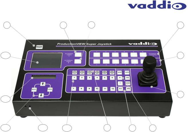
ProductionVIEW Super Joystick Front Panel Controls (Figure 2):
1 |
2 |
3 |
4 |
14 |
|
|
5 |
6
13 |
|
|
|
|
|
12 |
11 |
10 |
9 |
8 |
7 |
1)MASTER POWER (system on/off)
2)EXTERNAL VIDEO A
•Selector Switch assigns External Video Input A to the Built-in 4” LCD Monitor
3)EXTERNAL VIDEO B
•Selector Switch assigns External Video Input B to the Built-in 4” LCD Monitor
4)EXTERNAL CONTROL A
•For controlling external devices via tally contacts (contact closure) or RS-232
5)EXTERNAL CONTROL B
•For controlling external devices via tally contacts (contact closure) or RS-232
6)HALL EFFECT JOYSTICK
•Pan (left, right), Tilt (up, down), Zoom (twist +, -) Camera Control
7)CAMERA CONTROLS
•Brightness (+, -) and Focus (Far, Near) controls
8)CAMERA CONTROLS
•BLC – Back Light Compensation and AWB – Automatic White Balance
9)CAMERA SELECTION
•Selects camera to be controlled by the Joystick and camera controls (brightness, focus, etc.)
10)CAMERA PRESETS
•Twelve (12) camera presets per camera can be saved under the Camera Preset switches
•In “6InCam 6Local”, Presets 1 - 6 are stored in the cameras & 7 - 12 are stored internally
11)LCD DISPLAY CONTROLS (recessed mini screw driver adjustments on front edge)
•Left Adjustment - Color Saturation (up, down), Right Adjustment - Brightness (up, down)
12)MENU CONTROLS
•Select, up, down and Cancel used to navigate menu system (see pages 9 & 10)
13)LCD Display for Menu Control
•See Appendix 1 for detailed description
14)4” LCD PREVIEW MONITOR
•Select between EXTERNAL VIDEO A and EXTERNAL VIDEO B inputs
ProductionVIEW Super Joystick Manual 341-565 Rev. B |
Page 4 of 16 |
ProductionVIEW Super Joystick
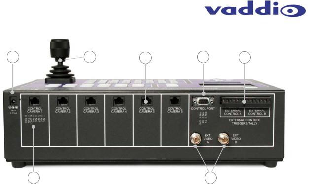
ProductionVIEW Super Joystick Back Panel I/O and Controls (Figure 3):
|
|
|
Pin 2: TX |
|
1 |
2 |
3 |
Pin 3: RX 4 |
5 |
|
|
|
Pin 5: GND |
|
7 |
Pin 6: |
GND |
6 |
Pin 7: |
TXD |
Pin 8: RXD
1)POWER INPUT
•Use only the 18 VDC, 2.75A power supply provided with the ProductionVIEW Super Joystick. Use of any other power supply may cause damage to the ProductionVIEW and to the products attached.
•Connector 5.5mm OD, 2.5mm ID, positive center
2)3-AXIS HALL-EFFECT JOYSTICK
•Pan/Tilt/Zoom Control, Side view - shown with rubber boot.
3)CAMERA CONTROL PORTS on RJ-45 connectors
•One camera control port per camera (no daisy-chaining required)
4)RS-232 CONTROL PORT
•DB-9 for RS-232 control of internal functions (Pin 2 = TX, Pin 3 = RX, Pin 5 = GND) for use with external controllers or external production switchers
5)EXTERNAL CONTROL TRIGGERS/TALLYS
•For use with tally lights or external devices (i.e. video switchers or control systems). These external control contacts correspond directly to front panel EXTERNAL CONTROL A (1 through 6) and EXTERNAL CONTROL B (1 through 6) switches on the front panel.
•External Control Triggers/Tally contacts are latching, TTL type. These triggers are not relays and no voltage should be applied to these triggers at any time. The triggers are configurable as Active High or Active Low.
6)EXTERNAL VIDEO INPUTS (A & B)
•Composite video inputs on BNC connectors, 1 V p-p, and 75Ω for display on built-in 4” preview monitor.
7)RJ-45 Pin–outs
•Pin-out reference for RS-232 control over Cat-5 (Cat. 5e) cabling
•Pin 6: GND
•Pin 7: TXD
•Pin 8: RXD
ProductionVIEW Super Joystick Manual 341-565 Rev. B |
Page 5 of 16 |
 Loading...