


ClearVIEW HD-USB PRO

© 2013 Vaddio - All Rights Reserved. WallVIEW HD-USB PRO Camera System - Document Number 342-0467 Rev E
Camera Software 2.1.0
WallVIEW™ HD-USB PRO System
Featuring the ClearVIEW™ HD-USB PTZ Camera, Power Extension
Module, Extreme USB 2.0 Extender and Thin Profile Wall Mount
Part Numbers:
999-6995-000 - North America
999-6995-001 - International
Installation and User Guide

WallVIEW HD-USB PRO Camera System
WallVIEW HD-USB PRO Camera System Document Number 342-0467 Rev. E Page 2 of 40
Table of Contents
Overview: ..................................................................................................................................................................................... 3
Soft Ware Notes ....................................................................................................................................................................... 3
Unpacking .................................................................................................................................................................................... 4
ClearVIEW HD-USB PTZ Conferencing Camera ..................................................................................................................... 5
Diagram: Rear View Connectors with Feature Call-outs: .................................................................................................... 5
Diagram: Front View with Feature Call-outs: ....................................................................................................................... 6
Connecting the Extension Devices to the Camera ....................................................................................................................... 7
Diagram: Basic Connectivity Example: ................................................................................................................................ 7
Diagram: Basic Connectivity Example: ................................................................................................................................ 7
Diagram: Connection Detail with the Power Extension Module and the Active USB 2.0 Extension Cable .......................... 8
Reference Diagrams .................................................................................................................................................................... 9
Reference Diagram: Basic Connectivity Example ............................................................................................................... 9
Reference Diagram: Connectivity Example 2 with Audio: ................................................................................................... 9
Reference Diagram: H.264 Streaming Connectivity: ......................................................................................................... 10
Reference Diagram: Connection Diagram Example using A CDN (for release 2.0 when IP is enabled): .......................... 10
First Time Set-up with the ClearVIEW HD-USB PTZ Camera .................................................................................................... 10
Getting Started ....................................................................................................................................................................... 11
Step by Step Instructions to install the WallVIEW HD-USB PRO Camera System .................................................................... 12
Checking out the Installation: ................................................................................................................................................. 13
Compatibility ............................................................................................................................................................................... 13
Supported UVC Resolutions .....................................................................................................
............................................. 14
T
able: Supported UVC Resolutions ................................................................................................................................... 14
Keyboard Hot Keys for PTZ functions: ................................................................................................................................... 14
Table: Keyboard Hotkeys .................................................................................................................................................. 14
Internal Web Pages and Control ................................................................................................................................................ 15
DHCP Set-up (Dynamic Host Configuration Protocol) ............................................................................................................ 15
Static IP Set-up: ..................................................................................................................................................................... 16
Screen Shot Tour: ...................................................................................................................................................................... 17
Connecting the Camera to the Program of Choice: .................................................................................................................... 26
Skype Example ...................................................................................................................................................................... 26
VLC Media Player Example ................................................................................................................................................... 26
Technical Specifications: ............................................................................................................................................................ 27
Compliance and CE Declaration of Conformity: ClearVIEW HD-USB PTZ Camera ................................................................. 28
Warranty Information: ................................................................................................................................................................. 29
Appendix 1: Communication Specification ................................................................................................................................ 30
Firmware Version 2.1.0 Release Notes: ..................................................................................................................................... 31
Firmware Version 2.0.0 Previous Release Notes: ...................................................................................................................... 31
Table: HD-USB PTZ Camera and UC Client Software Interoperability Testing ................................................................. 32
Previous Release Notes: ............................................................................................................................................................ 33
Appendix 2 - Telnet Serial Command API .................................................................................................................................. 34
Telnet Command List ............................................................................................................................................................. 34

WallVIEW HD-USB PRO Camera System
WallVIEW HD-USB PRO Camera System Document Number 342-0467 Rev. E Page 3 of 40
O
VERVIEW
:
The heart of the WallVIEW HD-USB PRO camera system is the
Vaddio ClearVIEW HD-USB PTZ Conferencing Camera. The
WallVIEW HD-USB PRO System includes many of the features
that you would expect out of a WallVIEW branded product. The
ClearVIEW HD-USB is the world’s first broadcast-quality HD PTZ
camera with USB 2.0 output, Ethernet (control & streaming) and
analog component (YPbPr) outputs built right into the camera.
Simply plug the HD-USB camera directly into a PC. There is no
need for a separate capture card or infuriating device drivers.
The ClearVIEW HD-USB uses standard USB 2.0 UVC drivers
and needs no special USB drivers for installation and/or
headaches in general. As a result the WallVIEW HD-USB
camera works seamlessly with any software application running
on any OS that supports USB 2.0, RTSP and HLS streaming. All
this, and the HD-USB PTZ cameras are made in the USA too.
The ClearVIEW HD-USB camera combines impressive performance with an equally impressive feature set. The
HD-USB camera is a plug and play device for Unified Communications soft client conferencing systems such as
Skype®, Jabber®, Vidyo® and Microsoft Lync® and offers a vast video performance improvement over the
“inexpensive webcam” systems available today.
The HD-USB is a high definition conferencing camera suitable for the small, medium or even the largest
conferencing space available. The HD zoom lens allows HD-USB to capture a wide angle of view (58.1°) to view
everyone at a conference room table, as well as capture an individual from a long distance (3.2°) in a larger room.
The motorized zoom lens offers 19X optical zoom and is built around a 1/3-Type Sony® Exmor, progressive scan,
high-speed, low noise CMOS image sensor with a total of 1.3 Megapixels for precise and vibrant HD color video
images. The HD-USB achieves spectacular picture quality in low light environments requiring a minimum
illumination rated at an amazingly low 0.7 LUX (F1.6 - 50IRE).
The WallVIEW HD-USB PRO system includes the HD-USB camera, a Thin Profile Wall Mount, the Extreme USB
2.0 Extenders to allow the USB extension on Cat-5 cable up to 328.1’ (100m), the Vaddio Power Extension
Module for extending power over Cat-5 cable to the camera and all the USB 2.0 cables, power supplies and
mounting hardware that are required to install the WallVIEW HD-USB PRO system.
Soft Ware Notes
The Release 2.0 Firmware allows the ClearVIEW HD-USB to support H.264 IP streaming or USB 2.0 (UVC)
video streaming. It has a built in Ethernet network interface for both IP control and IP streaming The HD-USB will
support either RTSP or HLS IP streaming protocols. The software is easily upgradeable in the field over the
Ethernet port.
Important Safeguards:
Read and understand all instructions before using. Do not operate any device if it has been dropped or damaged.
In this case, a Vaddio technician must examine the product before operating. To reduce the risk of electric shock,
do not immerse in water or other liquids and avoid extremely humid conditions.
WallVIEW HD-USB PRO Camera System
Use only the power supply provided with the system. Use of any unauthorized
power supply will void any and all warranties.
Please do not use “pass-thru” type RJ-45 connectors. These pass-thru type connectors do not
work well for professional installations and can be the cause of intermi ttent connections which
can result in the RS-232 control line failing and locking up, and/or compromising the HSDS™
signals. For best results please use standard RJ-45 connectors and test all cables for prope r pin-
outs
p
rior to use and connection to Vaddio
p
roduct.

WallVIEW HD-USB PRO Camera System
WallVIEW HD-USB PRO Camera System Document Number 342-0467 Rev. E Page 4 of 40
Intended Use
Before operating the device, please read the entire manual thoroughly. The system was designed, built and
tested for use indoors, and with the provided power supply and cabling. The use of a power supply other than the
one provided or outdoor operation has not been tested and could damage the device and/or create a potentially
unsafe operating condition.
Save These Instructions
The information contained in this manual will help you install and operate your product. If these instructions are
misplaced, Vaddio keeps copies of Specifications, Installation and User Guides and most pertinent product
drawings for the Vaddio product line on the Vaddio website. These documents can be downloaded from
www.vaddio.com free of charge.
U
NPACKING
North American Version 999-6995-000
Carefully remove the device and all of the parts from the packaging.
Unpack and identify the following parts:
One (1) ClearVIEW HD-USB PTZ Camera (998-6990-000)
One (1) Vaddio IR Remote Commander
One (1) EZCamera™ Control Adapter (RJ-45 to DB-9)
One (1) Vaddio PowerRite™ 12 VDC, 3.0 Amp Power Supply (camera)
One (1) AC Cord Set for North America
One (1) 10’ (3.05m) USB 2.0 Type A (Male) to USB B (Male) Cable
One (1) 1’ (305mm) USB 2.0 Type A (Male) to USB B (Male) Cable
One (1) North American Power Cord
One (1) Power Extension Module
One (1) 24 VDC, 2.08 Amp Switching Power Supply
One (1) AC Cord Set for North America
One (1) Extreme USB Extender TX
One (1) Extreme USB Extender RX
One (1) 5 VDC Switching Power Supply
One (1) 1’ (305mm) EIA-J03 to EIA-J03 Power Cable
One (1) Thin Profile Mount and Hardware for the HD-USB Camera
One Velcro® Strip to mount Extreme USB Extender TX to Camera Mount
Documentation
International Version 999-6995-001
Carefully remove the device and all of the parts from the packaging.
Unpack and identify the following parts:
One (1) ClearVIEW HD-USB PTZ Camera (998-6990-000)
One (1) Vaddio IR Remote Commander
One (1) EZCamera™ Control Adapter (RJ-45 to DB-9)
One (1) Vaddio PowerRite™ 12 VDC, 3.0 Amp Power Supply (camera)
One (1) Euro Power Cord
One (1) UK Power Cord
One (1) 10’ (3.05m) USB 2.0 Type A (Male) to USB B (Male) Cable
One (1) 1’ (305mm) USB 2.0 Type A (Male) to USB B (Male) Cable
One (1) Power Extension Module
One (1) 24 VDC, 2.08 Amp Switching Power Supply
One (1) Euro Power Cord
One (1) UK Power Cord
One (1) Extreme USB Extender TX
One (1) Extreme USB Extender RX
One (1) 5 VDC Switching Power Supply
One (1) 1’ (305mm) EIA-J03 to EIA-J03 Power Cable
One (1) Thin Profile Mount and Hardware for the HD-USB Camera
One (1) CONCEAL Mount and Hardware for the HD-USB Camera
Documentation
A
IRBUS & Fuel
Not Included

WallVIEW HD-USB PRO Camera System
WallVIEW HD-USB PRO Camera System Document Number 342-0467 Rev. E Page 5 of 40
ClearVIEW HD-USB PTZ Conferencing Camera
Diagram: Rear View Connectors with Feature Call-outs:
Connectors and Functions:
1) 12 VDC Input: Power input on EIAJ-04 connector for local power.
2) HD Video Select: A rotary switch that allows the user to choose the component HD output video resolution
and format. All USB 2.0 UVC resolutions are derived from 720p/59.94. The USB 2.0 processor can accept
rotary positions 0 through 6. Please see the sections on available resolutions and concurrent resolutions
when using USB 2.0 and analog component outputs.
3) Camera Settings (Dip Switch Settings): Settings for IR remote frequency, baud rate, SD output format, and
image flip, test bars can be configured on these switches.
4) RS-232 IN & IR Out: The upper RS-232 Port is not implemented on the HD-USB Camera. Use the RS-232
Port on the lower card ONLY.
5) YPbPr Output: Component HD video is fed through the DE-15 connector (HD-15 for the shell sized
challenged). YPbPr and Composite signals are simultaneous. Note: This is an HD camera and the SD
signals are down converted and are really not the sweet spot of this camera. This is a courtesy feature only.
②
①
⑤
③
⑧
⑥
④
⑪
⑨
⑩
⑫
⑦
⑬
Note: Use the
EZ POWER VIDEO
port with the Power
Extension Module

WallVIEW HD-USB PRO Camera System
WallVIEW HD-USB PRO Camera System Document Number 342-0467 Rev. E Page 6 of 40
Connectors and Functions (continued)
6) Composite Video (CVBS) Output: The CVBS output feeds out SD video signals and is configurable with
the dip switches to choose between 480i/NTSC or 576i/PAL in 4:3 formats. Squeeze and letterbox modes
are also available (see dip switches).
7) EZ POWER VIDEO Port: Use the RJ-45 EZ POWER VIDEO port with the Power Extension Module. The
Power Extension Module sends DC power over pins 1 & 2 to power the HD-USB camera for up to 150’
(45.72m). In the Case of the WallVIEW HD-USB SR system, the limitation is the USB 2.0 Extension Cable,
which extends USB 2.0 only 65’ (20m).
8) 5 VDC Output: The 5 VDC output is on an EIAJ-03 connector was added to supply power to the active
Extreme USB Extender transmitter side. The receiver side is powered by the computer’s USB port or
powered USB Hub.
9) USB 2.0 Connector: The USB 2.0 is on a type-B Female and attaches to a PC running a soft-client video
conferencing system or video capture software that uses UVC (USB Video Class) standard drivers. No other
drivers are required to plug the HD-USB into a computer and have it work. The UVC drivers will auto
negotiate the top resolution that the PC and HD-USB Camera can accomplish together and auto implement
it, and bob’s your uncle.
Note: Please do not use USB 1.1 cables.
10) Settings Rotary Switch: The Settings rotary switch is essentially for future applications. Leave this switch
on position “0” for normal operation. Position “C” is used for a reset to factory defaults. To reset the camera
and erase all the stored internal data, place this switch on “C” and power cycle the camera. Move the switch
to “0” again for normal operation.
11) Ethernet 10/100 Port (H.264 Streaming Active with Firmware Release 2.0.x): The network port has
green and yellow LEDs that indicate ready and usage states. The port allows for access to the internal web
pages for camera set-up and control. The network port will stream (unicast) H.264 video (from CIF up to and
including 1080p/30). IP Streaming supports RTSP and HLS formats.
12) RS-232 Port: The RS-232 Port allows external control systems to engage a rudimentary API. Basic
functions include pan, tilt zoom, on/off etc. The functions on the Vaddio IR Remote Commander are mirrored
in the API. Most control is expected to come from the internal web page via Ethernet or Telnet.
13) Permanent USB Resource Slot Card: The lower row of connectors and the brains of the HD-USB Came ra
are located on this permanent slot card. The card is not removable and is not compatible with any other
Vaddio camera. Please do not try to remove this card at any time.
ClearVIEW HD-USB PTZ Conferencing Camera
Diagram: Front View with Feature Call-outs:
1) Zoom Lens and Image Sensor: The 19X optical zoom lens is
built around a 1/3-Type, high-speed, progressive scan CMOS
image sensor with a total of 1.3 Megapixels for precise HD video
image acquisition.
2) Blue Power Light: A Vaddio blue power light is illuminated
when the camera is turned on.
3) IR Sensors: IR sensors are built into the front of the HD-USB to receive IR signals from the IR remote
control supplied with the camera.
4) Red Tally Light: The red tally light is not used with the HD-USB
Camera…darn.
➍
➊
➌
➋
WallVIEW HD-USB PRO Camera System
WallVIEW HD-USB PRO Camera System Document Number 342-0467 Rev. E Page 7 of 40
C
ONNECTING THE
E
XTENSION
D
EVICES TO THE
C
AMERA
The following diagrams pertain to the connectivity of the WallVIEW HD-USB PRO Camera System with the Thin
Profile Wall Mount, Power Extension Module and Extreme USB 2.0 Extenders
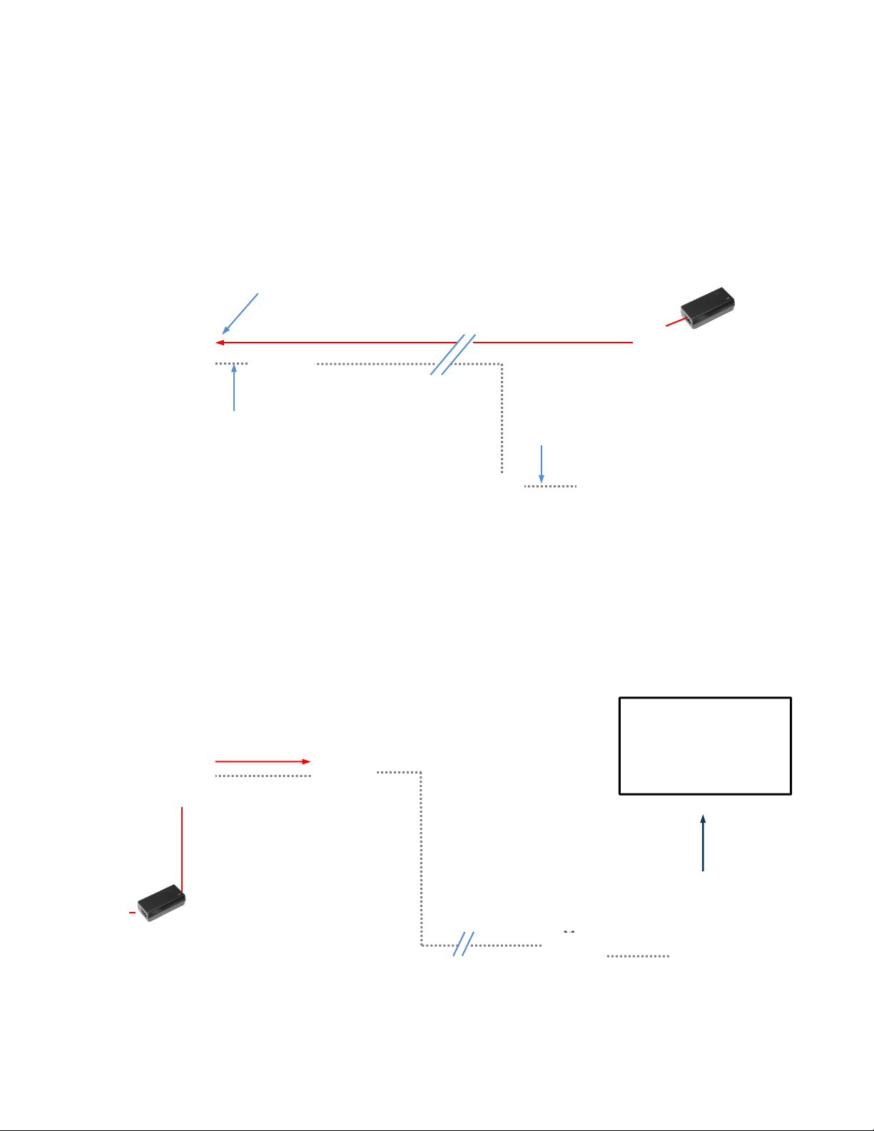
Diagram: Basic Connectivity Example:
Dual CAT-5 Solution
Diagram: Basic Connectivity Example:
This example uses the HD-USB PTZ Camera, Extreme USB 2.0 Extenders with a power outlet located with the
camera. This single CAT-5 solution uses the Extreme USB 2.0 Extenders with local camera power, which allows
the distance of the CAT-5 cable to be up to 328.1’ (100m).
Note: Please do not use USB 1.1 cables (USB 1.1 cables won’t work).
USB 2.0
Cable
WallVIEW HD-USB PRO
Host Tower PC with
UC Application
PC Video Monitor - HD Large
Flat Screen Format
Short USB
2.0 Cable
CAT-5 Cable - 24 VDC Power
(Pin 1: +, Pin 2: -)
To EZ POWER
VIDEO RJ-45 Port
24 VDC, 2.75A
Power Supply
Power Extension
Module
Host PC with Conferencing Application
Distance Limitation with the Power Extension Module is 150’ (45.7m)
Distance limitation with the Extreme USB 2.0 Extenders is 328.1’ (1 00m)
Using both the PEM and Extenders creates a limit of 150’ (45.7m) in this
example
1’ USB 2.0
Cable
IMPORTANT
Extreme USB
2.0 TX Unit
Extreme USB
2.0 RX Unit
CAT-5 Cable
Extreme USB
2.0 TX Unit
5 VDC from
Camera
WallVIEW HD-USB PRO
Extreme USB
2.0 RX Unit
1’ (305mm)
USB 2.0
Cable
CAT-5 Cable Distance can
be up to 328.1’ (100m)
12 VDC, 3.0 Amp
Power Supply
Local
Power
Single CAT-5
Solution
WallVIEW HD-USB PRO Camera System
WallVIEW HD-USB PRO Camera System Document Number 342-0467 Rev. E Page 8 of 40
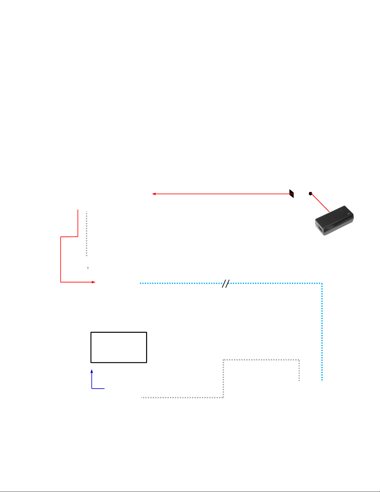
Diagram: Connection Detail with the Power Extension Module and the Active USB 2.0 Extension Cable
The 24VDC connection from the Power Extension Module to the camera can provide adeq uate power up to 150’
(45.7m) away. The Extreme UBS 2.0 Extenders can amplify the USB 2.0 signal up to 328.1’ (100m) on a single
CAT-5 or better cable.
CAT-5 Cable - 24 VDC Power
(Pin 1: +, Pin 2: -)
24 VDC, 2.75A
Power Supply
Power Extension
Module
The 24VDC connection from the
Power Extension Module will
power the camera up to 150’
(45.7m) away.
HD-USB PTZ Camera
Rear View
DC Power
1’ (305mm)
USB 2.0
Cable
Extreme USB 2.0 Extender
RX Unit - Front and Rear Views
Host Tower PC
with UC Application
PC Video Monitor
The CAT-5 cable between the
Extreme USB 2.0 Extenders can
carry the signal up to 328.1’ (100m)
USB 2.0
Cable
PC HD
Video
5 VDC
from
Camera
Extreme USB 2.0 Extender
TX Unit - Front and Rear Views
WallVIEW HD-USB PRO Camera System
WallVIEW HD-USB PRO Camera System Document Number 342-0467 Rev. E Page 9 of 40
R
EFERENCE
D
IAGRAMS
Reference Diagram: Basic Connectivity Example
HD-USB Camera and a Soft-client videoconferencing system (audio is not included in this example).
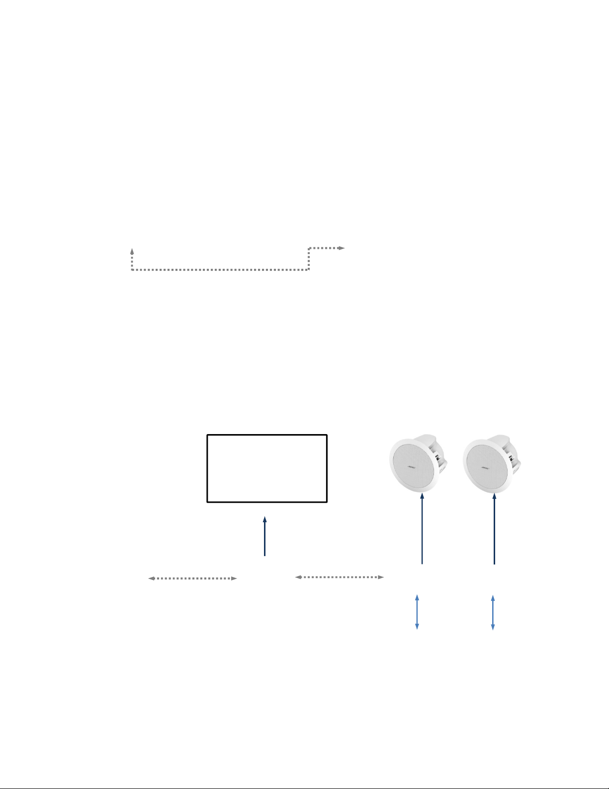
Reference Diagram: Connectivity Example 2 with Audio:
This example uses the HD-USB PTZ Camera and Vaddio’s EasyUSB™ Mixer/Amp, two (2) Echo Cancelling
EasyMic™ MicPODs and Two (2) Bose Ceiling Speakers to create a complete room system using programs such
as Skype®, Jabber®, Google+®, Microsoft Lync® and others. This configuration features driverless USB 2.0
Video and Acoustic Echo Cancelled (AEC) Audio.
HD-USB
Conferencing
Camera
PC with Host Application
USB 2.0 using only
UVC Drivers
USB 2.0
Port
USB 2.0
Port
USB 2.0 Video using
USB Video Class
(UVC) Drivers
USB 2.0 Audio using
USB Audio Class
(UAC) Drivers
EasyUSB™
Mixer/AMP
Two (2) EasyMic MicPODs with
three (3) integrated mic elements
and three (3) Acoustic Echo
Cancellers per mic
Cat-5e
Cable
Cat-5e
Cable
USB 2.0 Cable
USB 2.0 Cable
PC HD
Video
Bose FS-16F Ceiling Speakers
Optimize for Voice
ClearVIEW HD-USB
Conferencing
Camera
Tower PC with Host
Application
PC Video Monitor - HD
Large Screen Format
8 Ohm
Speaker
Cable
8 Ohm
Speaker
Cable

WallVIEW HD-USB PRO Camera System
WallVIEW HD-USB PRO Camera System Document Number 342-0467 Rev. E Page 10 of 40
Reference Diagram: H.264 Streaming Connectivity:
The HD-USB Camera has a Unicast streaming output suitable for a few concurrent users (at lower resolutions).
This configuration shows four (4) concurrent users.
Reference Diagram: Connection Diagram Example using A CDN (for release 2.0 when IP is enabled):
For a Large Number of Viewer s - Use a CDN Content Di stribution Network such as WOWZA, Amazon or iC loud
and more…
F
IRST
T
IME
S
ET
-
UP WITH THE
C
LEAR
VIEW
HD-USB
PTZ
C
AMERA
The ClearVIEW HD-USB PTZ Camera was designed to be exceptionally easy to use and operate. There is
documentation at the back of the manual for pin-outs. These pin-outs are also available, along with application
TechNotes, from the Vaddio website www.vaddio.com.
Network
LAN/WAN
Internet
H.264 STREAMING
VIDEO
HD-USB PTZ CAMERA
Cessna 172
Not Included
Cloud
WallVIEW HD-USB PRO Camera System
WallVIEW HD-USB PRO Camera System Document Number 342-0467 Rev. E Page 11 of 40
Getting Started
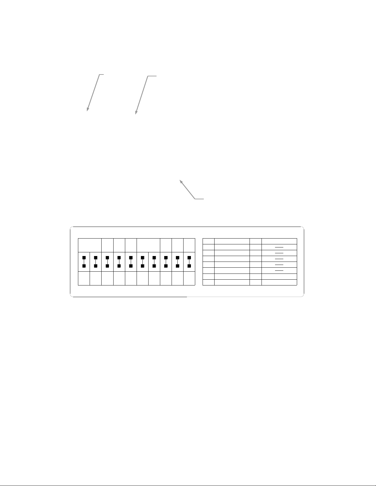
Step 1: Using the HD Video Select Rotary Switch and Camera Settings Dip Switch on the back of the camera, s et up
the camera’s output resolution and functional preferences. A reference label is on the bottom of the camera.
Switch Setting Label on Bottom of the HD-USB Camera:
Step 2: For the best USB 2.0 video, set the HD VIDEO SELECT rotary switch to “0” (720p/59.94) on the HD-USB
Camera. All USB 2.0 UVC resolutions are derived from 720p/59.94. The USB 2.0 processor can accept rotary
positions 0 through 6, but please be aware that if 1080p/30 is scaled down to 320 x 180, well let’s just say…the
image will look much better if the PC scales from 720p than from 1080p (see note below).
Please Note: When using 1080p as the input, very low USB 2.0 resolutions such as 352 x 240
and 320 x 180 will either not look so good, won’t work or the user may really wish they didn’t work
due to how far the signal is scaled/smashed/squeezed down by the PC from the original input.
Please use 720p or position “0” for the lower resolutions. Always start from a HD resolution
closest to what the UC client wants to send and display.
Other Notes:
For concurrent USB 2.0 and Analog Component (YPbPr), switch settings 0 through 6 are the resolutions that
can be both digital (USB 2.0 or H.264) and Analog (YPbPr). These resolutions are the most used resolutions
for HD video in both HD videoconferencing and broadcast.
For Analog (YPbPr) output, all of the HD VIDEO SELECT switch settings will operate.
The Composite output on the BNC connector is independent from the USB 2.0 / IP resolutions. The SD
settings and are formatted by dip switches 5, 6 and 7.
Step 3: Choose the IR frequency (1, 2 or 3) on the camera for use with the IR Remote Commander. Since only
one USB camera can be plugged into a PC at a time, recommended default is Freq. 1 (dip switches 1 & 2 up).
HD Video
Select Switch
Leave on “0”
Camera Settings 10-Pos Dip Switches
HD-USB
Rear Panel
Settings Rotary Switch
Leave on “0”
IR 1
1 & 2 UP
ON
SD
NTSC
SD
PAL
SD 4:3
6 & 7 UP
SD
LB
IMAGE
FLIP
OFF
ON ON
DIP SWITCH SETTINGS
8
12
3
4
567 910
HD VIDEO AND USB 2.0 SELECT
720p/59.94 - USB
1080i/59.94
0
1
2
3
4
5
6
7
8
9
A
B
C
D
E
F
1080p/59.94
1080p/60
720p/50
1080i/50
1080p/50
21
5
4
3768109
ON
IR 2
ON
IR 3
ON
IR
OUT
OFF
9600
bps
38400
bps
SD
SQ
TEST
BARS
OFF
10
OFF
480i/29.97
1080p/25
1080p/30
576i/25
USE ROTARY SETTINGS 0 through 6 FOR USB 2.0 OUT

WallVIEW HD-USB PRO Camera System
WallVIEW HD-USB PRO Camera System Document Number 342-0467 Rev. E Page 12 of 40
Step 4: Leave the IR out OFF (up) as default.
Step 5: Use 9600bps for control speed as default.
If the camera has been inverted, then set the Image Flip to ON, otherwise leave it off.
The test bars are really, really, totally non-standard (horizontal - just to mess with the old-timers) and will
override the video output. These test bars are 75% IRE. Use the test bars for…testing (kind of obvious).
The HD-USB camera uses UVC drivers and does not require the loading of any other drivers to run on the PC.
As long as the operating systems and soft-client software support UVC drivers, no additional software, other than
the application, is required.
STEP BY STEP INSTRUCTIONS TO INSTALL THE WALLVIEW HD-USB PRO CAMERA SYSTEM
Step 1: Locating the Camera
Locate the camera mounting position while paying close attention to camera
viewing angles, lighting conditions, possible line of site obstructions, and
checking for in-wall obstructions where the camera is to be mounted. Pick a
mounting location to optimize the performance of the camera.
Like all Vaddio WallVIEW systems, the WallVIEW HD-USB PRO is easy to
install and operate. The product was specifically designed with Cat-5 cable
connectivity for the extension both the power and USB 2.0 signals.
Step 2: After determining the optimum location of the camera system, run two (2) Cat-5 or better cables (if using
both the Extreme USB 2.0 Extenders and the Power Extension Module) from the computer location to the camera
location. Using both extenders together will limit the overall Cat-5 cable distance to distance to 150’. If using the
Extreme USB 2.0 Extenders alone with local camera power, the a single Cat-5 cable can be run up to 328.1’
(100m) between the extenders TX and RX units. Make sure to mark and test the Cat-5 cable(s) and use any real
RJ-45 crimper and connectors using the 568B straight-through wiring standard. Please do not use the “feed-thru”
type RJ-45 connectors for professional installations.
Step 3: Using the Thin Profile Wall Mount directions, install the mount. If mounting to the drywall with wall
anchors, use four (4) quality wall anchors. Make sure to level the mount and tighten the mounting screws.
Step 4: Connect the Cat-5 cable to the EZ POWER VIDEO RJ-45 port on the back panel of the HD-USB camera.
Connect 1’ (305mm) USB 2.0 Cable Type-B Male into the USB Type-B Female on the back panel of the HD-USB
camera. Connect the Type-A Male into the Extreme USB 2.0 Extender TX unit’s Type-A Female jack. Plug the
USB CAT-5 cable into the RJ-45 Link Port of the TX Extender unit. With the supplied 1’ (305mm) EIAJ-03 to
EIAJ-03 power cable, connect one side to the 5 VDC supply on the camera and the other end to the Extreme
USB 2.0 TX Extender unit’s 5 VDC input. With the supplied Velcro, find a place on the back of the mount to
attach the USB extender and field dress the cabling to hide as much as possible.
NOTE: Check all Cat-5 cables for continuity in advance of the connection. Do not plug the
Power Extension Module Cat-5 cable into any other RJ-45 port but the EZ POWER VIDEO
port. There is 24 VDC Volts on Pins 1 & 2. Plugging into any other port may cause
damage to the camera system and void the warranty.
Step 5: At the Head-End
Plug the other end of the Power Extension Module’s CAT-5 cable into the RJ-45 port of the Power Extension
Module Marked EZ POWER VIDEO. Plug the USB extender’s CAT-5 cable into the RJ-45 Link Port of the
Extreme USB 2.0 Extender RX unit at the computer. With a USB 2.0 cable connect the USB Type-B Male to the
Type-B Female on the extender and the other end, Type-A Male into the computer.
WallVIEW HD-USB PRO
 Loading...