


ProductionVIEW FX
©2007 Vaddio - All Rights Reserved. ProductionVIEW FX - Document Number 341-451 Rev. C
Installation and User Guide
V
V
A
A
D
D
D
D
I
I
O
O
™
™
P
P
R
R
O
O
D
D
U
U
C
C
T
T
I
I
O
O
N
N
V
V
I
I
E
E
W
W
™
™
F
F
X
X
Camera Control Console with Video Switching, Video Transitions and
Automated Control Functionality
Model Number 999-5200-000 (NTSC)
Model Number 999-5200-001 (PAL)
Camera and Electronic Products for Integrators
ProductionVIEW FX
ProductionVIEW FX Manual 341-451 Rev. C Page 2 of 16
ProductionVIEW FX Overview
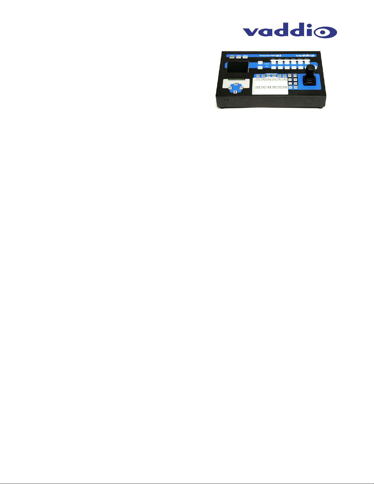
Like the original ProductionVIEW, the ProductionVIEW FX
incorporates all of the same matrix video switching, camera
preset control and joystick camera control functionality that
has made the ProductionVIEW one of the most fully
featured video consoles on the market today. In addition to
the ProductionVIEW’s feature rich platform, the new
ProductionVIEW FX (Figure 1) delivers user selectable,
frame synchronized transitions that are completely
seamless, professional and without compromise in quality.
Among the included transitions are straight cuts, fades (in and out), cross fades (one image fading into
another) and wipes (up, down, side to side and corner). The user can select the transition and the
transition time, up to four seconds, to automatically activate as the inputs are switched on the main and
preview buses. The ProductionVIEW FX is extremely clean, extraordinarily powerful and remarkably
easy to use. Once again, the overall value of the ProductionVIEW FX is unmatched in today’s camera
control, video mixing and video switching market.
The ProductionVIEW FX’s unique attributes start with Joystick control of up to six (6) PTZ cameras
directly (without daisy chaining) and the six discrete camera control ports auto-sense the PTZ camera
attached. Whether it is Sony® or Canon® or Vaddio PTZ cameras, the ProductionVIEW FX senses
the cameras attached and provides for seamless control of the camera functions.
Video transitions are user selectable and include the most popular, real world transition effects that
are used every day in video productions. In the menus, the user can activate fades, cross fades,
wipes as well as using the main bus off control to fade to black to end a video production segment.
The transition times are assignable from zero (0) to four (4) seconds. The ProductionVIEW FX uses
FPGAs (field programmable gate arrays) for producing both pristine cuts and exceptionally smooth
transitions providing for a professional video performance and amazingly clean video throughput.
The inclusion of an internal 6 x 2 Video Switcher (for Preview and Main) and a built-in 4” LCD Video
screen set the ProductionVIEW FX apart allowing complete monitoring of both Main and Preview
sources at the touch of a button. Both the Main and Preview outputs are given S-Video, Composite
Video outputs and Stereo Audio outputs for Audio-follow-Video applications.
Each of the six camera inputs has been provided with twelve (12) camera presets that are stored
internally to the ProductionVIEW FX or six (6) in the camera and six (6) in the FX. Each input also
has S-Video or composite video inputs. Inputs 5 & 6 have stereo audio inputs for DVD or VCR inputs.
Each of the six cameras can also be adjusted individually for the environment in which it operates
with auto/manual focus, auto/manual brightness, backlight compensation and one-push automatic
white balance. The camera control ports are RJ-45F and are easily connected to the Vaddio camera
packages using the Vaddio Cat. 5 wiring standard.
The ProductionVIEW FX is equipped with an Automatic Camera Switching Mode like the Vaddio
ControlVIEW products. Cameras 1 and 2 can have six presets each assigned to input triggers like
TouchVIEW™ buttons, StepVIEW™ Mats or AutoVIEW™ Active IR ceiling mount sensors. Or,
Camera 1 can be configured to respond to all 12 input triggers alone. Cameras 3 through 6 are
configured to each accept a single trigger for preset activation as well.
The ProductionVIEW FX also has 4 assignable Logic outputs for controlling external A/V or RGB
switchers as well.
Key Technical Features:
Camera Auto-Sensing - The ProductionVIEW FX is capable of identifying through auto-sensing of
each camera attached. Control codes for the following cameras are built-in:
Vaddio WallVIEW Series Cameras
Vaddio CeilingVIEW 70 PTZ Series Cameras
Vaddio HideAway Series Cameras
Vaddio CeilingVIEW & CeilingVIEW Mega-Pro
Vaddio Model Series and PTZCam Series Cameras
Sony EVI-HD1, EVI-D30, EVI-D100 & EVI-D70 & Sony BRC-300 & BRC-H700
Canon VC-C50i & VC-C50iR
Figure 1: ProductionVIEW FX Camera Control Console
ProductionVIEW FX
ProductionVIEW FX Manual 341-451 Rev. C Page 3 of 16
Key Technical Features (continued):
Video Transitions
Video transitions are truly seamless with exceptional video quality. The transition times are
assignable from zero (0) to four (4) seconds and include:
Fades (in, out, fade to black with main off)
Cross Fades (one image fades into another)
Wipes (side to side, up and down and corner)
Straight Cuts
3-Axis Hall-Effect Joystick - High quality Hall-Effect joystick allows for control of Pan/Tilt (X/Y
coordinates) and the Zoom function (twist for Z or zoom axis). This non-contacting joystick uses
industrial quality magnets and sensors, providing solid, consistent performance throughout its entire
lifetime.
Operator (manual) and Presenter (automatic) modes - In addition to a manual or “operator” mode,
an Automatic Camera Switching mode for switching to camera presets assigned to Vaddio input
triggers like the StepVIEW mats, AutoVIEW IR or TouchVIEW buttons is provided.
Camera Control - Each camera input has individual control for Pan/Tilt/Zoom and auto/manual focus,
auto/manual brightness, backlight compensation and one-push automatic white balance.
72 Total Camera Presets – 12 Presets per camera input channel are stored internally and are not
dependent on the internal presets of the camera.
Master RS-232 Control Port - In addition to the six (6) discrete camera control ports, the Master
control port can be used to control any of the internal functions of the ProductionVIEW FX or for
software updates.
Intended Use:
Before operating the Vaddio ProductionVIEW FX, please read the entire manual thoroughly. The system
was designed, built and tested for use indoors, and with the provided power supply and cabling. The use
of a power supply other than the one provided or outdoor operation has not been tested and could
damage the camera and/or create a potentially unsafe operating condition.
Save These Instructions:
The information contained in this manual will help you install and operate your Vaddio ProductionVIEW
FX. If these instructions are misplaced, Vaddio keeps copies of Specifications, Installation and User
Guides and most pertinent product drawings for the Vaddio product line on the Vaddio website. These
documents can be downloaded from www.vaddio.com free of charge.
Important Safeguards:
Read and understand all instructions before using. Do not operate any device if it has been dropped or
damaged. In this case, a Vaddio technician must examine the product before operating. To reduce the
risk of electric shock, do not immerse in water or other liquids and avoid extremely humid conditions.
UNPACKING:
Carefully remove the device and all of the parts from the packaging.
Unpack and identify the following parts:
One (1) ProductionVIEW FX Camera Control Console, Part Number 999-5200-000
One (1) Vaddio PowerRite 18 VDC, 2.75A Power Supply
One (1) Vaddio AC Cord Set
Documentation and Manuals
Use only the power supply provided with the ProductionVIEW FX system.
Use of any unauthorized power supply will void any and all warranties.
ProductionVIEW FX
ProductionVIEW FX Manual 341-451 Rev. C Page 4 of 16
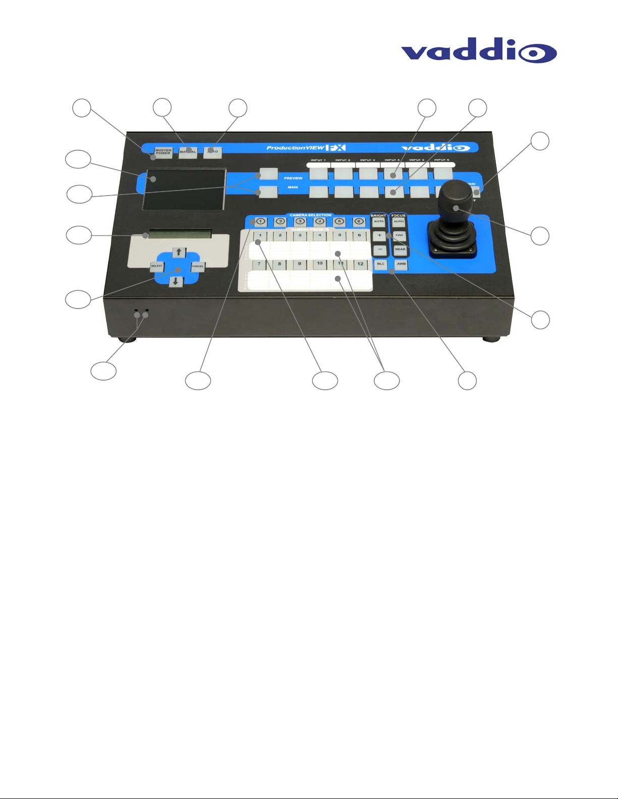
ProductionVIEW FX Front Panel Controls (Figure 2):
1) System Power Switch (system on/off)
2) Manual Mode Switch
a. Console is in manual or “Operator Mode” and all video switching is manual
3) Automatic Mode Switch
a. Console is in automatic or “Presenter Mode” and the video switching is handled with the
trigger inputs
4) PREVIEW Input Select
a. Selects the camera input to be sent to the PREVIEW Output
5) MAIN Input Select Switch
a. Selects the camera input to be sent to the MAIN Output
6) MAIN OFF Switch
a. Turns MAIN output off (outputs black) and places the PTZ cameras in standby mode
7) 3-Axis Hall-Effect Joystick controller
a. Pan (left, right), Tilt (up, down), Zoom (twist +, -)
8) Camera Controls
a. Brightness (+, -)
b. Focus (Far, Near)
9) Camera Controls
a. BLC – Back Light Compensation
b. AWB – Automatic White Balance
10) Camera Preset Switches
a. Twelve (12) camera presets per camera can be saved under the Camera Preset switches
11) Camera Selection Switches
a. Selects camera to be controlled by Joystick and camera controls (brightness, focus, BLC,
AWB)
12) Menu Controls
a. Select, up, down and Cancel used to navigate menu system (see pages 9 & 10)
13) LCD Display for Menu Control
a. See Appendix 1 for detailed description
ProductionVIEW FX
ProductionVIEW FX Manual 341-451 Rev. C Page 5 of 16
Pin 2: TX
Pin 3: RX
Pin 5: GND
Front Panel Controls (continued)
14) PREVIEW and MAIN Selection Switches
a. PREVIEW assigns the PREVIEW camera input to be displayed on the 4” Monitor
b. MAIN assigns the MAIN camera input to be displayed on the 4” Monitor
c. NEITHER picked, displays neither
IMPORTANT NOTE: With no panel selection switch selected, the LCD Monitor will turn off.
15) 4” Diagonal LCD Monitor
a. (10.16cm diagonal) switches between PREVIEW, MAIN and NEITHER (black)
16) LCD Display Controls (recessed mini screw driver adjustments) on front edge panel
a. Left – Color Saturation (up, down)
b. Right – Brightness (up, down)
17) Dry Erase - White labeling areas
a. To notate positions, presets, functions, etc..., use dry erase pens only
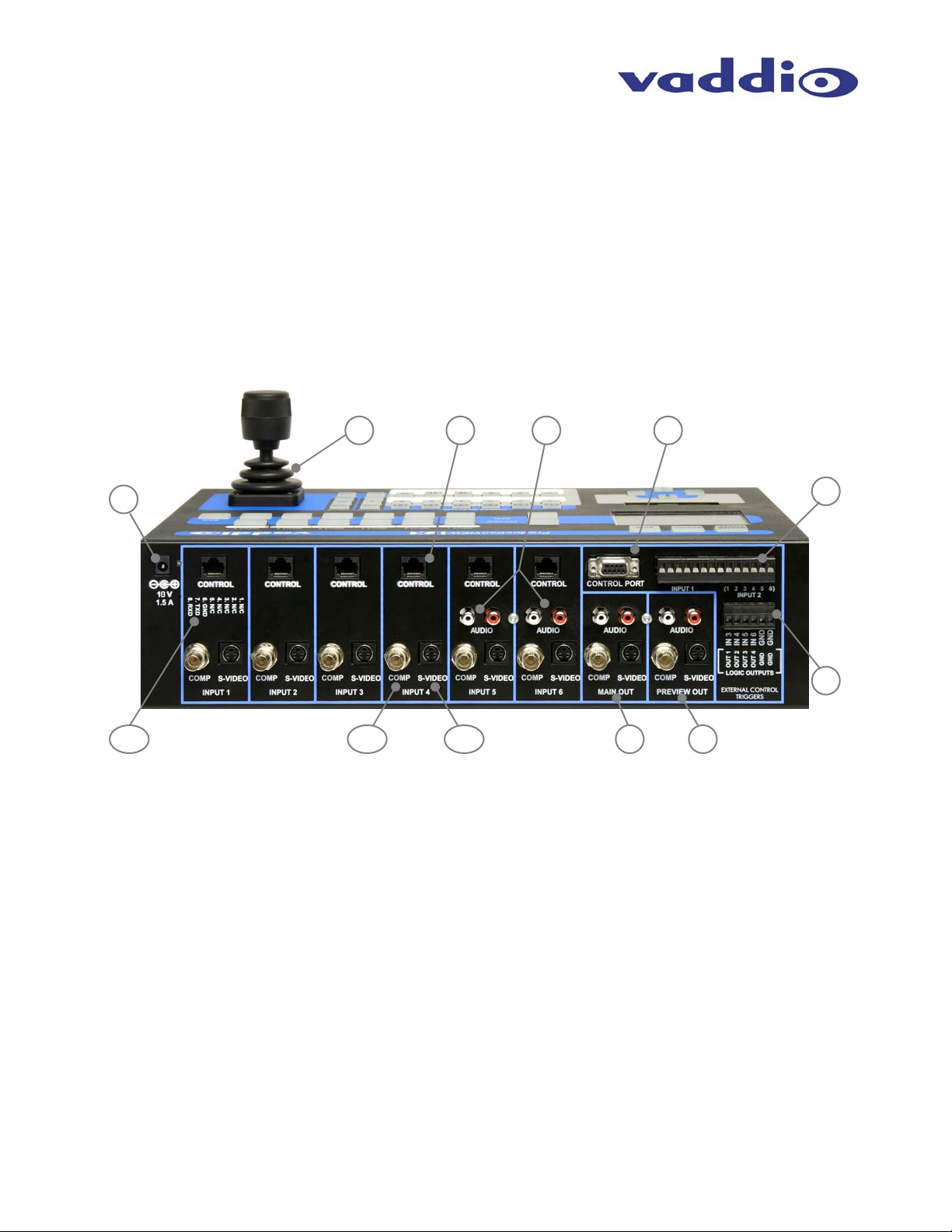
ProductionVIEW FX Back Panel I/O and Controls (Figure 3):
1) Power Input
a. (Note: Use only the 18 VDC, 2.75A power supply provided with the ProductionVIEW FX)
2) 3-Axis Hall-Effect Joystick
a. Pan/Tilt/Zoom Control, Side view - shown with rubber boot
3) Camera Control Ports on RJ-45 connectors
a. One camera control port per camera (no daisy-chaining required)
4) Input 5 and 6 Stereo Audio Inputs (audio-follow video)
a. Inputs 5 and 6 have line level stereo audio inputs for use with DVD, VCR, etc…
5) Control Port Input
a. DB-9 for RS-232 control of internal functions (Pin 2 = TX, Pin 3 = RX, Pin 5 = GND)
6) Input Triggers for use in AUTOMATIC mode
a. Input Triggers for input channels 1 and 2
b. Configurable in two modes (6 triggers for Input 1 and 6 triggers for Input 2, or 12 triggers
for input 1 only)
c. Supports Vaddio AutoVIEW IR, StepVIEW, TouchVIEW and MicVIEW trigger inputs
7) Multifunction Triggers (assignable either as input triggers or logic outputs)
a. Input Triggers for input channels 3, 4 5 & 6 with GND
i. Memory locations 3-1, 4-1, 5-1, 6-1
b. Logic outputs follows MAIN Outputs 1 through 4 with GND
c. Additional GND connector for multiple trigger configurations
 Loading...