


ProductionVIEW HD MV

©2014 Vaddio - All Rights Reserved ● ProductionVIEW HD MV ● Document Number 342-0241 Rev. G
PRODUCTIONVIEW™ HD MV
High Definition Camera Control Console with Integrated
Multiviewer Touch Screen Control, Multi-View Control Panel
Layout Options and Expanded I/O Capabilities
Part Number 999-5625-000 North America
Part Number 999-5625-001 International
Installation and User Guide
Installation and User Guide

ProductionVIEW HD MV
ProductionVIEW HD MV Manual - Document Number 342-0241 Rev G Page 2 of 36
Inside Front Cover - Blank

ProductionVIEW HD MV
ProductionVIEW HD MV Manual - Document Number 342-0241 Rev G Page 3 of 36
Overview:
The Vaddio™ ProductionVIEW HD MV Production
Switcher with integrated camera controller and
multiviewer is a powerful, cost effective and easy
to operate platform for live presentation
environments. With Vaddio’s revolutionary
TeleTouch™ Touch Screen Control Panel
(optional, sold separately), production operators
can easily see and switch all live video feeds and
create “video thumbnails” of preset camera shots
with the touch of their finger.
ProductionVIEW HD MV is a broadcast quality,
6x2; multi-format, seamless video mixer that also
provides two discrete outputs for dual bus program
feeds (two independent 6 x 1 switchers/mixers).
Accepting any combination of input signals from
analog HD YPbPr video, RGBHV, SD (Y/C and
CVBS) video with Input 6 providing a DVI-I input,
the ProductionVIEW HD MV supports HD
resolutions up to and including 1080p/60fps.
The outputs have been configured for analog
(YPbPr, RGBHV and SD) and digital (DVI-D) video
support allowing for either a standard preview
output or multiviewer preview output with support
for two monitors or the multiviewer output
supporting a Vaddio TeleTouch Touch Screen
Control Panel.
The optional TeleTouch™ Touch Screen Control
Panel allows the camera operator to see and
switch all the live video feeds by simply touching
the windows that they want controlled. The
Vaddio TeleTouch Touch Screens are available in
two sizes; 18.5” rack-mount (7-RU) version or a
22” with base.
Each camera input can have up to 12 stored
“video thumbnails” of each preset camera shot.
These video thumbnail images provide an easy
way to identify and recall preset camera positions.
The Multi-View Touch Screen Control Panel
Layout Options for the TeleTouch Touch Screen
Control Panel allows integrators to match the
touch screen layout to the number of camera,
computer or other video input sources that are
connected to the ProductionVIEW HD MV.
The Single or Dual Bus Multiviewer Output mode
allows separate Preview and Multiviewer Video
Outputs to be displayed. The Preview and
Multiviewer Video Output Menus are used to
select and set the Preview or Multiviewer video
output resolutions.
The ProductionVIEW HD MV control surface is laid out to allow even a novice to operate the system with minimal
training. ProductionVIEW HD MV is unmatched in today’s camera control, video mixing and video switching
market.
ProductionVIEW HD MV
Camera Control Console
*ProductionVIEW HD MV TeleTouch 22”
Multiviewer Touch Screen Control Panel
(Simulated Multiviewer Output)
*Optional
Multi-View Four-Input Layout Display for
*TeleTouch Touch Screen Control Panel
(Simulated Multiviewer Output)

ProductionVIEW HD MV
ProductionVIEW HD MV Manual - Document Number 342-0241 Rev G Page 4 of 36
Optional TeleTouch Multiviewer Touch Screen Control Panel with Multi-View Panel Layout Options:
The TeleTouch Multiviewer Touch Screen Control Panel (optional) with the new Multi-View touch screen control
panel layout options allows integrators to match the touch screen layout to the number of camera, computer or
other video input sources that are connected to the ProductionVIEW HD MV.
(Simulated Multiviewer Output)
The multiviewer maximizes the potential screen size available for previewing live feeds and prevents unused
blank multi-viewer input windows from being seen. Multi-View allows the user to choose from four to six input
windows and provides two larger preview and program windows with red and green tally window borders, which
indicate the current output selections.
The TeleTouch Touch Screen Control Panel also eliminates the need for individual preview monitors and allows
the camera operator to see and switch all the live video feeds by simply touching the windows that they want
controlled. Each camera input can have up to 12 stored “video thumbnails” of each preset camera shot. These
video thumbnail images provide an easy way to identify and recall preset camera positions on a per input basis in
the preview window that greatly simplifies overall console operation.
TeleTouch Touch Screen
Control Panel with
Multi-View Four-Input Layout
TeleTouch Touch Screen
Control Panel with
Multi-View Five-Input Layout
TeleTouch Touch Screen
Control Panel with
Multi-View Six-Input Layout
TeleTouch Touch Screen Control Panel with
Multi-View Four-Input Layout
Two-Inputs Displayed
TeleTouch Touch Screen Control Panel with
Multi-View Four-Input Layout
Three-In
p
uts Dis
p
la
y
ed

ProductionVIEW HD MV
ProductionVIEW HD MV Manual - Document Number 342-0241 Rev G Page 5 of 36
Key Technical Features:
Vaddio TeleTouch Touch Screen Controller (optional): The ProductionVIEW HD MV outputs can provide
either a standard preview output or a multiviewer preview output with support for two monitors, one of the
outputs supporting a Vaddio TeleTouch Touch Screen Controller.
The Vaddio TeleTouch Touch Screen Controller allows the operator to see and switch all live feeds by
touching the windows. The ProductionVIEW HD MV outputs can provide either a standard preview output or a
multiviewer preview output with support for two monitors, one of the outputs supporting a Vaddio TeleTouch
Touch Screen Controller. The Vaddio TeleTouch Touch Screens are available in two sizes; 18.5” (P/N: 999-
5520-185) rack-mount or a standard 22” (P/N: 999-5520-022) with base.
Multiviewer: The ProductionVIEW HD MV multiviewer feature eliminates the need for individual preview
monitors. The multiviewer output allows the operator to see all live video feeds displayed on a single monitor.
Multi-View Panel Layout Options: This feature allows the user to choose from four, five or six input windows
on the multiviewer screen image and also provides two larger preview and program windows with red and
green tally window borders, which indicate the current output selections. The Multi-View feature maximizes
the potential screen size available for previewing live feeds and prevents unused blank multiviewer input
windows from being seen.
Single or Dual Bus Multiviewer Output Mode: Single or Dual Bus Multiviewer Output allows separate
Preview and Multiviewer Video Outputs to be displayed in either Single Bus or Dual Bus mode. The Preview
and Multiviewer Video Output Menus are used to select and set the Preview or Multiviewer video output
resolutions. The Preview DVI-D Output can be set to a selected discrete output resolution and the YPbPr
Output can be set to a selected discrete output resolution.
Camera Video Thumbnail Presets: Each camera input can store up to 12 stored “video thumbnails” of
preset PTZ camera preset positions for 72 total presets. The Vaddio TeleTouch Touch Screen Controller
provides the ability to switch to any one of the 12 stored “video thumbnails” with the touch of a finger.
Video Switcher: The internal video switcher can be configured as a traditional video switcher, using the
TAKE button, or DUAL BUS mode (essentially two 6 x 1 video switchers).
Anything In, Anything Out: The inputs auto-detect the video resolution and the outputs have user
configurable discrete video resolution settings. See the specifications on page 26 for additional information
on all of the resolutions supported.
Graphic Insertion: Graphics may be inserted as “lower-thirds” using the Lower Screen Graphics (LSG)
feature. LSG can be set up to cover the bottom
¼, ⅓, ½ or full screen, with 10 adjustable steps of
transparency levels between the graphic and the video image behind it.
Graphic Templates: A variety of graphic templates are included on a DVD supplied with the
ProductionVIEW HD MV in both Keynote and PowerPoint, to help guide users in creating professional Lower
Screen Graphics quickly and easily.
3-Axis, 1-Button, Hall Effect Joystick: The ProductionVIEW HD MV includes a 3-Axis Hall Effect joystick
controller to smoothly operate up to six (6) PTZ cameras directly (without daisy chaining). Vaddio, Sony®,
Canon® and Panasonic® PTZ cameras are compatible with ProductionVIEW HD MV (see the list below of
specific models).
Camera Presets: Each input can store up to12 preset PTZ camera preset positions for 72 total presets.
Automatic Mode: The ProductionVIEW HD MV console is equipped with an automatic camera switching
mode (for compatible PTZ cameras on inputs 1 & 2), and when combined with Vaddio’s StepVIEW™ Mats,
MicVIEW™, PresenterPOD™ or other trigger devices, allows ProductionVIEW HD MV to be set up for use
without an operator present.
Tally Outputs/External Triggers: The ProductionVIEW HD MV can be configured for six (6) Program tally
outputs and six (6) Preview tally outputs for controlling tally lights on external sources. It can also be
configured for up to twelve external trigger inputs.
ProductionVIEW HD MV
ProductionVIEW HD MV Manual - Document Number 342-0241 Rev G Page 6 of 36
Additional Features: Other features include auto/manual focus, auto/manual iris, backlight compensation
and automatic white balance for compatible PTZ cameras.
Camera Auto-Sensing: The ProductionVIEW HD MV is capable of auto-sensing each PTZ camera
attached. Control codes for the cameras are automatically loaded into ProductionVIEW (see specifications
for supported models).
Video Transitions:
Video transitions are seamless with exceptional video quality. Transition time is adjustable from 0.1 seconds
to 4 seconds, and includes:
Cross Fades (one image fades into another)
Wipes (9 different patterns)
Straight Cuts
Fade To Black (by pressing and holding the MIX/FTB button)
Important Note: When using the Multiviewer output (technically still the Preview output), the
transitions are not visible. The multiviewer gives a representation of the Program bus, but without
transitions. Please use a separate Program monitor to view the actual Program feed.
Intended Use:
Before operating the device, please read the entire manual thoroughly. The system was designed, built and
tested for use indoors, and with the provided power supply and cabling. The use of a power supply other than the
one provided or outdoor operation has not been tested and could damage the device and/or create a potentially
unsafe operating condition.
Save These Instructions:
The information contained in this manual will help you install and operate your product. If these instructions are
misplaced, Vaddio keeps copies of Specifications, Installation and User Guides and most pertinent product
drawings for the Vaddio product line on the Vaddio website. These documents can be downloaded from
www.vaddio.com free of charge.
Important Safeguards:
Read and understand all instructions before using. Do not operate any device if it has been dropped or damaged.
In this case, a Vaddio technician must examine the product before operating. To reduce the risk of electric shock,
do not immerse in water or other liquids and avoid extremely humid conditions.
Use only the power supply provided with the system. Use of any unauthorized
power supply will void any and all warranties.
Please do not use “pass-thru” type RJ-45 connectors. These pass-thru type connectors do not
work well for professional installations and can be the cause of intermittent conn ections which
can result in the RS-232 control line failing and locking up, and/or compro mising the HSDS™
signals. For best results please use standard RJ-45 connectors and test all cables for proper
p
in-outs
p
rior to use and connection to Vaddio
p
roduct.

ProductionVIEW HD MV
ProductionVIEW HD MV Manual - Document Number 342-0241 Rev G Page 7 of 36
UNPACKING:
Carefully remove the device and all of the parts from the packaging.
For 999-5625-000 North American Version, unpack and identify the following parts:
One (1) ProductionVIEW HD MV Camera Control Console
One (1) Vaddio PowerRite™ 18 VDC, 2.75A Switching Power Supply
One (1) AC Power Cable
One (1) Laird 100 ohm ¼” Snap-On Rectangular Ferrite (for DC cable of the Power Supply)
One (1) DVD ROM with templates and sample graphics for Lower Scre en Graphics*
Documentation
For 999-5625-001 International Version, unpack and identify the following parts:
One (1) ProductionVIEW HD MV Camera Control Console
One (1) Vaddio PowerRite 18 VDC, 2.75A Switching Power Supply
One (1) Euro Power Cable
One (1) UK Power Cable
One (1) Laird 100 ohm ¼” Snap-On Rectangular Ferrite (for DC cable of the Power Supply)
One (1) DVD ROM with templates and sample graphics for Lower Scre en Graphics*
Documentation
Notes:
*User must supply their own compatible version of Keynote or PowerPoint to display and modify templates on the DVD ROM.

ProductionVIEW HD MV
ProductionVIEW HD MV Manual - Document Number 342-0241 Rev G Page 8 of 36
ProductionVIEW HD MV with Feature Call-outs:
1. Focus and Iris Controls: Focus and Iris can be adjusted from knobs on the console for real-time control of
these critical functions when in manual mode. Auto White Balance (AWB) and Backlight Compensation
(BLC) functions are available for compatible cameras.
2. Single Bus or Dual Bus Switching: ProductionVIEW HD MV can be configured as Program and Preview
buses or as discrete video outputs (i.e. one for high resolution IMAG and the other for delivery to a recording
or streaming device).
3. Lower Screen Graphics: Insert “lower third” and other graphics, through our unique LSG function. A variety
of sizes and transparency levels are available through buttons on the console.
4. Picture-In-Picture: Insert video in any quadrant of the program video output to add impact to your live
production. The PIP can be adjusted to three different sizes.
5. Wipe, Fade, Cut, Transition Speed and Fade to Black: Select from a variety of wipe patterns, mix or cut
from buttons on the control console. The fade to black (FTB) feature allows the Program output to fade to
black. Transition Speed allows a wipe or crossfade (mix) to be adjusted up to 4 seconds in duration.
6. Take Button: Pressing the Take button switches the input selected from Preview to Program in single bus
mode. In dual bus mode, it switches the input to the input that is flashing.
7. 3-Axis Hall Effect Joystick PTZ Camera and Speed Controls: Sony, Canon and Vaddio PTZ cameras can
be controlled via the 3-axis Hall-Effect Joystick built into ProductionVIEW HD MV. When the button on top of
the joystick is pressed, it will reposition the selected camera to its home position. Located above the joystick,
adjustable knobs for Pan, Tilt and Zoom speeds allow the operator extremely fine real-time camera control.
8. Camera Selector and Presets: Select a camera from the top row of buttons, and program (or recall) up to
12 preset shots per camera, using the camera preset control buttons.
9. 8-Line LCD Screen (for Menus and Status): The internal menu allows the user to configure the resolution
on the outputs, as well as other parameters built into the console. The LCD screen will also provide status to
current settings. See pages 20 to 24 for the menu structures and programmable functions.
10. Manual and Automatic Modes: In addition to a manual or “operator” mode there is an automatic camera
switching mode for PTZ camera presets assigned to Vaddio input triggers like the StepVIEW™ mats,
AutoVIEW™ IR or PresenterPOD.
②
①
③ ④
⑤
⑥ ⑦
⑧
⑨
⑩

ProductionVIEW HD MV
ProductionVIEW HD MV Manual - Document Number 342-0241 Rev G Page 9 of 36
ProductionVIEW HD MV, Rear View with Feature Call-outs:
1. Power Input: Use only the 18 VDC, 2.75A power supply provided with the ProductionVIEW HD MV.
2. Camera Control Ports on RJ-45 connectors: One camera control port per camera (no daisy-chaining
required). Compatible with Sony, Canon, Panasonic and Vaddio PTZ cameras. See page 7 for details on
cameras and camera systems compatible with ProductionVIEW HD MV.
3. Video Inputs 1-5: Each input 1 through 5 will accept either an HD (YPbPr) or RGBHV or SD (CVBS or Y/C,
with adapter cable) video signals selectable via internal menu on the DE-15-F connector. See the Video
Resolutions table on page 26 for all signals and resolutions supported.
4. Video Input 6: Input 6 is a DVI-I Input (DVI-D and DVI-A). See page 26 for supported resolutions.
5. Program Outputs: The Program outputs are on DE-15-F (HD-15) and DVI-D Connectors. The DVI-D
connector uses a HDMI 1.3 compliant transmitter, so with an adapter cable (DVI-D-M to HDMI) HDMI is also
output. The DE-15-F outputs HD (YPbPr) or RGBHV or SD (CVBS or Y/C, with adapter cable). The DVI-D
outputs DVI-D with sRGB color space and HDMI in YCbCr color space depending on the resolution chosen in
the menu. See page 26 for supported resolutions.
6. Preview/Multiviewer Outputs: The Program outputs are on DE-15-F (HD-15) and DVI-D Connectors. The
DVI-D connector uses a HDMI 1.3 compliant transmitter, so with an adapter cable (DVI-D-M to HDMI) HDMI
is also output. The DE-15-F outputs HD (YPbPr) or RGBHV or SD (CVBS or Y/C, with adapter cable). The
DVI-D outputs DVI-D with sRGB color space and HDMI in YCbCr color space depending on the resolution
chosen in the menu. When using the optional TeleTouch Touch Screen Controller, use the DVI-D Connector
and set the output to 1080p/60 HZ or 1080p/50 for best results. Both Preview/Multiviewer connectors will be
the same resolution. See page 26 for supported resolutions.
Note: Transitions and effects will only appear on the Program output.
7. Tally Outputs/External Triggers: Allows for connecting ProductionVIEW HD MV to up to six (6) Program
Tally outputs and up to six (6) Preview Tally outputs when in Manual Mode. These tally outs can be set to
Triggers and used in Automatic Control Mode, which accepts external input triggers such as Vaddio
AutoVIEW IR, StepVIEW, TouchVIEW or MicVIEW triggering devices. ProductionVIEW HD MV recalls the
Camera Switching and Camera Presets automatically as the triggers are received. In this mode, an operator
is not required. See the menu tree for exact deployment.
8. Control Port: DB-9 for RS-232 control of internal functions (Pin 2 = TX, Pin 3 = RX, Pin 5 = GND).
①
②
③
④
⑤
⑥
⑦
⑧

ProductionVIEW HD MV
ProductionVIEW HD MV Manual - Document Number 342-0241 Rev G Page 10 of 36
First Time Set-up with the ProductionVIEW HD MV:
ProductionVIEW HD MV is designed to be exceptionally easy to use and operate right out of the box. All of the
Vaddio standards for using video, power and control over Cat. 5 cabling are well documented and are in the
manual and available free of charge from the Vaddio website.
Getting Started:
Connect all of the cameras, monitors and peripheral devices to ProductionVIEW HD MV. The back panel has
five-standard DE-15-F (HD-15) connectors and one-DVI-I connector. Vaddio offers several different break out
cables including one for SD video inputs (either Y/C or composite) and two cables (3 ft. or 6 ft.) for high resolution
video (YPbPr or RGBHV). See accessory cables below.
Once you have connected all of your inputs, outputs and the PowerRite power supply, plug the AC cord into an
outlet. ProductionVIEW HD MV will boot up and scan for cameras. As ProductionVIEW HD MV boots up, it will
automatically scan each input to confirm which ports have compatible PTZ cameras connected. After boot up, a
menu will appear on the blue LCD screen.
Configuring Output Resolutions:
On the LCD screen, a chevron (>) will be
displayed next to the menu item that is currently
selected. Press the arrow down button (↓)
adjacent to the LCD screen, until the chevron is
next to “VIDEO OUTPUT MENU” and then press
the SELECT Button. Select PROGRAM OUTPUT,
which will display your options for video output
resolution for the PROGRAM OUTPUT.
Press the arrow down button to the appropriate resolution that is compatible with your video monitor and press the
SELECT Button. Press the CANCEL Button to exit out to the previous menu.
Repeat the process for your Preview Output. Once you have selected the Program and Preview output
resolutions, press the CANCEL Button to get back to the Main Menu. For additional information on the menu
structure, see pages 20 to 24 for additional information.
To set up the Preview out to be a multiviewer output, go to menu item “MULTIVIEWER” and select “ON”. If you
are using the optional Vaddio TeleTouch touch screen controller, go to “System Menu” and go to menu item
“TOUCH SCREEN”. Select either the 22” or the 18.5” monitor, which sets the correct touch screen coordinates.
Use 1080p/60 Hz or 1080p/50 Hz output resolution for the multiviewer and TeleTouch Monitor.
Auto Configured Input Resolutions:
The ProductionVIEW HD MV automatically configures and matches the input resolution for each camera
video output connected (with active video output) to an Input Port.
For Inputs 1 through 5, it will scan and select from 1080p/60 Hz (1920x1080) to 640x480@60 Hz. (including
SD 480i/29.97 NTSC and PAL 576i/25 Composite and S-Video).
Input 6 (DVI-I Port) will scan and select from 1080p/60 to 640x480@60 Hz.
Additional Programming: Review the ProductionVIEW HD Menu Structure for additional information on
programming specific parameters. For API and Programming Language, see information in the Appen dix.
Vaddio Accessory Cables and Part Numbers:
440-5600-000 – 15-pin to SD (Y-C / CVBS) breakout cable (female BNCs - 1’ / 308.4mm)
440-5600-001 – 15-pin to HD Component (YPbPr/RGBHV) breakout cable (male BNCs - 3’ / .914m)
440-5600-002 – 15-pin to HD Component (YPbPr/RGBHV) breakout cable (male BNCs - 6’ / 1.83m)
440-5600-003 – 15-pin to HD Component (YPbPr/RGBHV) breakout cable (female BNCs - 7” / 177.8mm)
440-5600-000: Optional SD Accessory
Cable (Y-C & Composite) Required for
SD signals into ProductionVIEW HD MV
Optional HD Accessory Cable
(3’ or 6’ length)
ProductionVIEW HD MV
ProductionVIEW HD MV Manual - Document Number 342-0241 Rev G Page 11 of 36
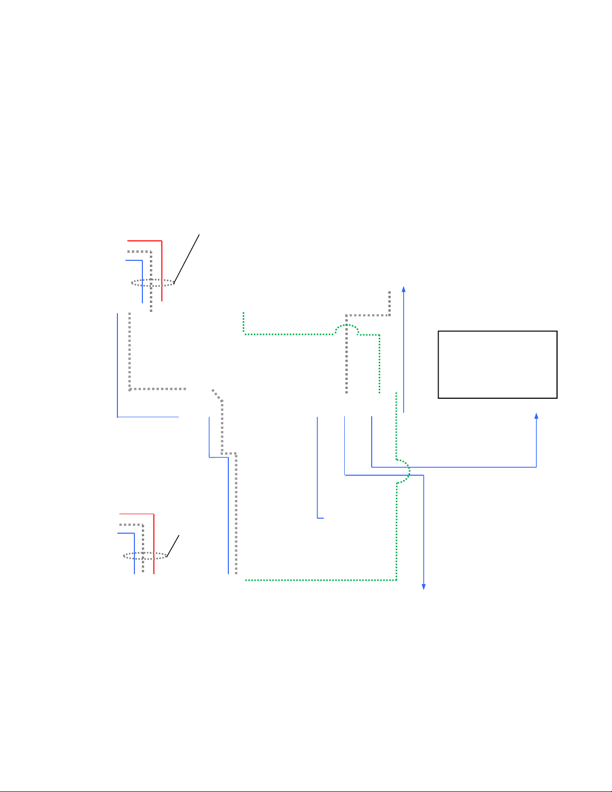
Basic System Configuration:
ProductionVIEW HD MV connected to two (2) Vaddio Quick-Connect™ HD-18 CCU Systems, PC, TeleTouch 22”
Touch Screen Controller and room projector. The TeleTouch Multiviewer Touch Screen Controller eliminates the
need for individual preview monitors and the touch screen greatly simplifies overall console operation. The
TeleTouch Multiviewer Touch Screen can be configured to display up to six input windows and two larger
Program bus and Preview bus windows with red and green tally window borders. It also displays video
thumbnails for up to 12 camera presets per camera input.
YPbPr
HD Video
Video, Control and
Power Cat-5e up to
500’ (152.4m)
RS-232
CAM 1
RS-232 on
DB-9
YPbPr
HD Video
DVI-D HD Video
Quick-Connect CCU
TeleTouch 22” Touch Screen
LCD Monitor with Base
3-LCD Projector
ProductionVIEW HD MV
Power
Vaddio HD-19 PTZ
Camera with EZIM
CCU Slot Card
Power
YPbPr
HD Video
RS-232 CAM 2
Video, Control
and Power Cat-
5e up to 500’
(152.4m)
DVI-D
OR
DVI-A
TALLY
TALLY
Quick-Connect CCU
Program Feed with Transitions
PC/MAC
Program Out
DVI-D to HDMI with
Adapter Cable 1080/60p
Multiviewer Out
at 1080/60p
Program Out
with Transitions
Simulated Video Feed
Vaddio HD-19 PTZ
Camera with EZIM
CCU Slot Card
 Loading...