


Installation and User Guide
VADDIO™ QUICK-CONNECT™ USB INTERFACE
Quick-Connect USB Interface for use with Vaddio Cameras with EZCamera™ Cat-5 interface, featuring Multi-format Outputs and IP or USB Streaming
Model Number 999-1105-038 (North America)
Model Number 999-1105-138 (International)
Images: Quick-Connect USB Front Panel ISO (above) and Rear Panel ISO (below)
© 2013 Vaddio - All Rights Reserved. Quick-Connect USB - Document Number 342-0653 Rev B

Quick-Connect USB Interface
Inside Front Cover - Blank
Quick-Connect USB, Document Number 342-0653 Rev. B |
Page 2 of 36 |

Quick-Connect USB Interface |
|
TABLE OF CONTENTS |
|
Overview................................................................................................................................................................................................................. |
4 |
Unpacking:.............................................................................................................................................................................................................. |
5 |
Compatible Vaddio Cameras .................................................................................................................................................................................. |
5 |
Table: Quick-Connect USB Interface and Vaddio Camera Compatibility ...................................................................................................... |
5 |
Table: WallVIEW Camera Packages with Quick-Connect USB.................................................................................................................... |
5 |
Quick-Connect USB Interface................................................................................................................................................................................. |
5 |
Image: Front Panel with Feature Call-outs ................................................................................................................................................... |
6 |
Image: Rear Panel with Feature Call-outs .................................................................................................................................................... |
7 |
Table: Quick Connect USB Rear Panel Dip Switch Settings ........................................................................................................................ |
7 |
Basic Application Diagrams .................................................................................................................................................................................... |
8 |
Diagram: Basic Wiring Configuration - Without Network or PC .................................................................................................................... |
8 |
Diagram: Basic ZoomSHOT WallVIEW USB Configuration - USB 2.0 Streaming ....................................................................................... |
9 |
Diagram: Basic IP Configuration - IP Streaming........................................................................................................................................... |
9 |
Diagram: Complex System with Audio........................................................................................................................................................ |
10 |
Vaddio Camera - First Time Set-up ...................................................................................................................................................................... |
10 |
Step By Step Quick-Connect USB Installation Instructions:............................................................................................................................. |
11 |
Quick-Connect USB Details ............................................................................................................................................................................. |
11 |
Software and OS Compatibility ............................................................................................................................................................................. |
12 |
Table: Supported UVC Resolutions ............................................................................................................................................................ |
12 |
Internal Web Pages and Control........................................................................................................................................................................... |
13 |
DHCP IP Set-up (Dynamic Host Configuration Protocol)................................................................................................................................. |
13 |
Static IP Set-up:................................................................................................................................................................................................ |
13 |
Quick-Connect USB Web Pages Tour: ............................................................................................................................................................ |
13 |
Screen Shot: Login...................................................................................................................................................................................... |
13 |
Screen Shot: Camera Control Page - No Camera Detected ...................................................................................................................... |
14 |
Screen Shot: User Menu - Camera Control Page....................................................................................................................................... |
14 |
Screen Shot: Admin Log-in ......................................................................................................................................................................... |
15 |
Screen Shot: Admin Menu - Camera Settings Page................................................................................................................................... |
16 |
Screen Shot: Admin Menu - USB 2.0 or IP Streaming Mode Page ............................................................................................................ |
18 |
Screen Shot: Admin Menu - Room Labels.................................................................................................................................................. |
18 |
Screen Shot: Admin Menu - DHCP Network Configuration ........................................................................................................................ |
20 |
Screen Shot: Admin Menu - Static IP Configuration ................................................................................................................................... |
20 |
Screen Shot: Admin Menu - Security.......................................................................................................................................................... |
21 |
Screen Shot: Admin Menu - Diagnostics .................................................................................................................................................... |
21 |
Screen Shot: Admin Menu - System Menu................................................................................................................................................. |
22 |
Screen Shot: Admin Menu - Update Confirmation...................................................................................................................................... |
22 |
Screen Shot: Admin Menu - Update in Progress ........................................................................................................................................ |
23 |
Screen Shot: Admin Menu - HELP.............................................................................................................................................................. |
23 |
Connecting the Quick-Connect USB and Camera to the PC and Program of Choice.......................................................................................... |
24 |
Skype Example:................................................................................................................................................................................................ |
24 |
VLC Media Player Example:............................................................................................................................................................................. |
24 |
General Specifications .......................................................................................................................................................................................... |
25 |
Compliance and CE Declaration of Conformity, Quick-Connect USB Interface ................................................................................................... |
26 |
Warranty Information............................................................................................................................................................................................. |
27 |
Appendix 1: Pin-outs for EZ-Power Video Cameras and Quick-Connect USB.................................................................................................... |
28 |
Table: EZ-POWER VIDEO RJ-45 Connector Pin-outs ............................................................................................................................... |
28 |
Table: Camera RS-232 Port........................................................................................................................................................................ |
28 |
Table: Quick-Connect USB DE-15 Pin-Output (Analog Component YPbPr).............................................................................................. |
28 |
Communication Specification................................................................................................................................................................................ |
28 |
Appendix 2 - Telnet Serial Command API ............................................................................................................................................................ |
29 |
Telnet Command List ....................................................................................................................................................................................... |
29 |
Quick-Connect USB, Document Number 342-0653 Rev. B |
Page 3 of 36 |

Quick-Connect USB Interface
OVERVIEW:
The Quick-Connect USB (QC-USB) Interface for Vaddio cameras is the most flexible video, power and control camera interface available on today’s market. This obustr system uses the Vaddio EZCamera™ Cabling system and uses two Cat-5 cables to provide power, return HSDS™ video and extends RS-232 control signaling to the camera up to a distance of 100’ (30.48m) with PTZ motorized cameras and up to 150’ (45.72m) with ZoomSHOT
& WideSHOT stationary POV cameras.
The Quick-Connect USB was designed to have multi-format digital and analog video outputs, it’s compatible with all existing and forthcoming Vaddio cameras, and like all other Vaddio interface products, it’s an
entirely |
unique interface that is easy |
|||||
use |
and |
represents a |
tremendous |
value |
||
for integrators and end users alike. |
Images: Quick-Connect USB Front Panel (up) and Rear Panel (below) |
|||||
|
|
|
|
|
|
|
Starting |
with |
the |
front |
panel, the |
backlit |
|
LCD |
is |
an |
ODV |
(omni-directional |
view), |
|
ABN (advanced black nematic) type of display that achieves superior front screen performance while offering a high contrast and wide viewing angle combined with high visibility.
The LCD will display the MAC (HW for Hardware) and addressesIP allowing for easy access to the internal webpages and camera settings for a PC or BYOD (bring your own device - laptop or tablet) over the network. The QC-USB has a front panel system reset switch as well as LED indicators on the front panel to show if the system is streaming USB 2.0 (UVC) MJPEG, IP (H.264) video or if the network is in general use (see images).
The QC-USB rear panel includes the USB 2.0 connection and the Ethernet 10/100 connection to provide for USB 2.0 streaming or IP video streaming and IP control. The USB 2.0 uses the standard UVC (Universal Video Class) drivers built-in to the OSof the computer, which means that no pesky programs or additional drivers and the associated headaches are required. Any compatible UC client using UVC drivers can be used (see compatible UC program list). The system also streams IP video (H.264) and supports both RTSP and HLS (HTTP Live Streaming, Apple’s variant on HTTP streaming).
An embedded web server provides for browser-based access of robotic camera controls, camera presets and rudimentary CCU functions (color and shading/painting controls) as well as the video configuration web pages. Analog and HDMI video outputs are also included and outputhet same video resolution that is sent from the camera simultaneously. The USB and IP resolutions are independent from the standard HD video outputs. The EZ-Power Video and RS-232 jacks are on RJ-45’s and are cabled to the corresponding RJ-45 connections on the Vaddio cameras. The RS-232 IN is supplied to connect a camera controller or control system if needed.
Intended Use:
Before operating the device, please read the entiremanual thoroughly. The system was designed, built and tested for use indoors with the power supply provided. Outdoor operation or use of a different power supply has not been tested and could damage the device and/or create a potentially unsafe operating condition.
Important Safeguards:
Read and understand all instructions before using. Do not operate any device if it has been dropped or damaged. In this case, a Vaddio technician must examine the product before operating. To reduce the risk of electric shock, do not immerse in water or other liquids and avoid extremely humid conditions.
Use only the power supply provided with the system. Use of any unauthorized power supply will void any and all warranties.
Please do not use “pass-thru” type RJ-45 connectors. These pass-thru type connectors do not work well for professional installations and can be the cause of intermittent connections which can result in the RS-232 control line failing and locking up, and/or compromising the HSDS (high speed differential) signals. For best results please use standard RJ-45 connectors and test all cables for proper pin-outs prior to use and connection to Vaddio product.
Quick-Connect USB, Document Number 342-0653 Rev. B |
Page 4 of 36 |

Quick-Connect USB Interface
Save These Instructions:
The information contained in this manual will help you install and operate your product. If these instructions are misplaced, Vaddio keeps copies of Specifications,stallationIn and User Guides and most pertinent product drawings for the Vaddio product line on the Vaddiobsitewe. These documents can be downloaded from www.vaddio.com free of charge.
UNPACKING:
Carefully remove the product and all of the included parts from the packaging.
Identify the following parts for each camera:
Quick-Connect USB Interface Kit (North America):
Part Number: 999-1105-038
One (1) Quick-Connect USB Interface (998-1105-038)
One (1) 24 VDC, 2.0 A Power Supply with Power Cord for North America
One (1) 6’ (1.83m) USB Type-A to Type-B Cable (Black)
Documentation
Quick-Connect USB Interface Kit (International):
Part Number: 999-1105-138
One (1) Quick-Connect USB Interface (998-1105-038)
One (1) 24 VDC, 2.0 A Switching Power Supply
One (1) 6’ (1.83m) USB Type-A to Type-B Cable (Black)
One (1) Euro Power Cable
One (1) UK Power Cord
Documentation
COMPATIBLE VADDIO CAMERAS
Table: Quick-Connect USB Interface and Vaddio Camera Compatibility
Camera Model |
Base Camera Model Number |
Notes |
ClearVIEW HD-18 |
998-6900-000 |
Full Compatibility |
ClearVIEW HD-19 |
998-6940-000 |
Full Compatibility |
ClearVIEW HD-20 |
998-6950-000 |
Image controls not fully implemented |
PowerVIEW HD-22 |
998-6960-000 |
Full Compatibility |
PowerVIEW HD-30 |
998-6970-000 |
Full Compatibility |
ZoomSHOT™ HD POV Camera |
998-6919-000 |
Full Compatibility |
WideSHOT™ HD Wide-Angle Manual PTZ |
998-6911-000 |
Full Compatibility |
REVEAL™ Series |
998-6925-000, 998-6935-000 |
CCU Functions to be added in future Rev |
CeilingVIEW™ HD-18 |
998-3018-000 |
CCU Functions to be added in future Rev |
Table: WallVIEW Camera Packages with Quick-Connect USB
Camera Model |
WallVIEW Kit Model Number |
Notes |
WallVIEW HD-18 USB |
999-6909-000 |
Full Compatibility |
WallVIEW HD-19 USB |
999-6949-000 |
Full Compatibility |
WallVIEW HD-22 USB |
999-6969-000 |
Full Compatibility |
WallVIEW HD-30 USB |
999-6979-000 |
Full Compatibility |
ZoomSHOT WallVIEW USB |
999-6919-000 |
Full Compatibility |
WideSHOT WallVIEW USB |
999-6911-000 |
Full Compatibility |
Maximum Cat-5 Cable Distance (by camera type)
Cat-5 cabling distance for PTZ cameras is up to 100’ (30.48m).
Cat-5 cabling distance for stationary POV cameras (ZoomSHOT & WideSHOT) is up to 150’ (45.72m).
Quick-Connect USB, Document Number 342-0653 Rev. B |
Page 5 of 36 |

Quick-Connect USB Interface
QUICK-CONNECT USB INTERFACE
Image: Front Panel with Feature Call-outs


1)LCD Blue Backlit Display:
20 x 2 Character, ODV (omni-directional view), ABNadvanced( black nematic) display with a high contrast and wide viewing angle combined with high visibility. The MAC address (labeled as “HW” for hardware) is on the top line, and the IP address (static or DHCP) is listed on the bottom line. This display with IP and MAC addresses allows for easy access to the embedded webserver and Vaddio camera settings for the PC or BYOD (bring your own device - laptop or tablet) users ofUC conference systems. Upon power up or power reset this display will indicate when the unit is in initialization mode.
2)Power/ System Reset Switch:
The System Reset switch on the front panel is a blue back lit-tactile switchthat will illuminate when power is present at the rear power connector. Pressing in and holding this switch 15643for1. seconds will restart/reinitialize the Quick-Connect USB interface.
3)NETWORK LED:
The green panel mount LED indicator will indicate thepresence of an Ethernet connection. This LED will blink to indicate network activity. If no network connection is made, the LED will remain off.
4)USB LED:
The blue panel mount LED indicates the presence of USBa connection to a PC (or mac). Blinking will indicate USB activity. If no USB connection is present the LED will remain off.
Quick-Connect USB, Document Number 342-0653 Rev. B |
Page 6 of 36 |
Quick-Connect USB Interface
Quick-Connect USB Interface |
|
Image: Rear Panel with Feature Call-outs |
|
|
|
|
|
|
||||
1)Power Input: 5.5mm OD x 2.5mm ID coaxial connector for the provided 24 VDC, 2.0 Amp switching power supply. The Quick-Connect USB Supplies Power to the attached camera.
2)5-Position Dip Switch: A 5-position dip switch allows the user to choose the HD video color space (YCbCr for HDMI and sRGB color space for DVI-D) on the HDMI output, configure for updates, and restore factory defaults when cycling power.
Table: Quick Connect USB Rear Panel Dip Switch Settings
Dip Switch |
Function |
Default |
Activation |
1 |
Future Use |
Up |
n/a |
|
|
|
|
2 |
Future Use |
Up |
n/a |
|
|
|
|
3 |
Color Space HDMI Connector |
Up = HDMI (YCbCr) |
Down = DVI (sRGB) |
|
|
|
|
4 |
Program/ Update |
UP = No Program |
DOWN = Ready To Program |
5 |
Future Use |
Up |
n/a |
|
|
|
|
All Down |
Reset to Defaults |
All UP |
ALL DOWN (with power cycle) |
3)RS-232 IN: Serial RS-232 input on a RJ-45 connector. This control port allows a Vaddio joystick controller orrd 3party controller (Crestron/AMX) to control the camera functions if the embedded webserver is not used for real time control.
4)RS-232 OUT TO CAMERA: Serial RS-232 output on RJ-45 connectsiav Cat-5 to the camera RS-232 input on the camera. Control signals from the embedded webserver arents via RS-232, or RS-232 from external controllers is relayed to the camera over this control port.
5)EZ POWER VIDEO: RJ-45 jack used to supply 24 VDC power to the camera and return differential video from the camera on Cat-5 cable at a maximum distance of 100’ (30.48m) withPTZ cameras and up to 150’ (45.7m) with stationary POV cameras (i.e. ZoomSHOT and WideSHOT).
6)YPbPr Output: Analog component video output on a DE-15 (HD15)onnector (resolution is set on the back of the camera). The YPbPr output resolution will be the same asthe HDMI output resolution. SD video resolutions (Y/C and
CVBS formats) are not supported byhe t Quick-Connect USB Interface; however some progressive frame analog component SD video is supported.
7)HDMI Output: The digital video output on the HDMI connector can either be YCbCr color space (normal HDMI mode) or can be changed to DVI-D color space (sRGB) for oldermonitors and devices. The HDMI and YPbPr outputs work simultaneously and are the same resolution (set at the camera).
8)Ethernet 10/100 Network RJ-45 Jack: The Ethernet jack will have yellow and green lights to indicate connectivity and activity of the network on that jack. The Ethernet jack willstream video (up to 1080p/30 H.264 and can be set from the internal web pages much like the HD-USB Camera. The resolutions will available in a three (3) stage quality format (High Quality, Good Quality and Standard Quality targets) and includes a range of CIF to 1080p/30.
9)USB 2.0 Connector: The USB 2.0 is on a Type-B female jack connectsad to a PC running a soft-client video conferencing system or video capture software that usesUVC (USB Video Class) standard drivers. No other USB 2.0 drivers are required to plug the QC-USB into a computer andhave it work. The UVC drivers will auto negotiate the top resolution that the PC and QC-USB can accomplish together and auto-implement.
Quick-Connect USB, Document Number 342-0653 Rev. B |
Page 7 of 36 |
Quick-Connect USB Interface
BASIC APPLICATION DIAGRAMS
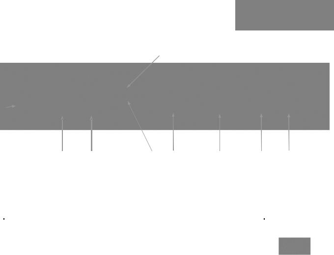
Diagram: Basic Wiring Configuration - Without Network or PC
`
PowerVIEW HD-22
PTZ Camera
Rear View
Quick-Connect
USB Interface
Rear Panel
24VDC, 2.0 A
Power Supply
Cat-5 Cable Distance up to 100’ (30.48m) for PTZ cameras
|
|
Cat-5 Cable for |
|
|
|
|
|
|
|||
Cat-5 Cable for |
Power and Video |
||||
(EZ-POWER VIDEO) |
|||||
RS-232 Control |
|||||
|
|
|
|||
|
|
← HD Video (HSDS differential) |
|||
|
|
|
|
|
|
|
|
Power → |
|||
|
|
|
|
|
|
HDMI
HD Video Video
YPbPr
RS-232 |
|
Control |
HDMI &YPbPr Notes: |
|
|
|
-Same Subject & Resolution |
|
(Determined by camera) |
|
Simultaneous Operation |
HD Monitor
(Simulated HD Video Feed)
ProductionVIEW Precision Camera Controller
Note: RS-232 can be run directly to the camera or through the Quick-Connect USB in this configuration
Quick-Connect USB, Document Number 342-0653 Rev. B |
Page 8 of 36 |
Quick-Connect USB Interface
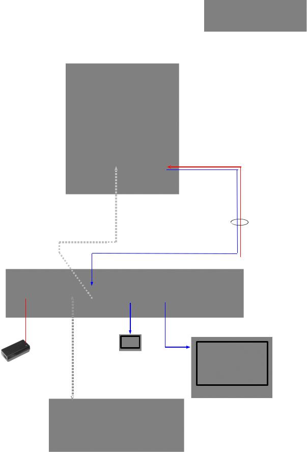
Diagram: Basic ZoomSHOT WallVIEW USB Configuration - USB 2.0 Streaming
Two (2) Cat-5 Cables carry Power, Video and Control Signals 
HDMI
Cable
HDMI Video Monitor
Simulated Video Feed
ZoomSHOT HD
Video Camera
Power to Camera > < HD Video to QC-USB
Two Cat-5 Cables up to 150’ (45.72m) for stationary
POV cameras such as ZoomSHOT and WideSHOT
Quick-Connect
USB Interface
USB 2.0 - MJPEG Video using
Standard UVC Drivers
Host PC with
UC Application
USB 2.0 Cable
Diagram: Basic IP Configuration - IP Streaming
HD-19 Camera to Quick-Connect USB out to Network for a remote network application.
ClearVIEW HD-19
HD Camera
Quick-Connect USB
Interface
|
Ethernet |
|
|
Two (2) Cat-5 Cables for |
|
|
|
Power, Video and Control |
IP (H.264) Streaming |
|
|
Distance up to 100’ (30.48m) |
|
||
RTSP or HLS |
Ethernet |
||
for PTZ cameras |
|||
|
|||
|
|
PC with Browser for Control
Network
Client (Video)
Network
Quick-Connect USB, Document Number 342-0653 Rev. B |
Page 9 of 36 |
Quick-Connect USB Interface
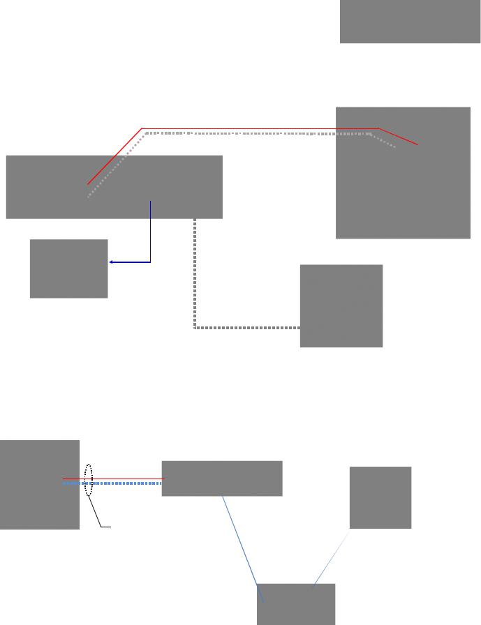
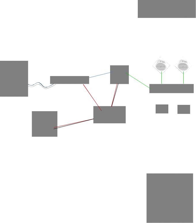
Diagram: Complex System with Audio
Local USB 2.0 streaming with Ethernet control, active UC Application and local audio system.
WallVIEW HD-30 USB System with Audio
PowerVIEW HD-30
HD Camera
Video, Power
and Control
Two Cat-5
Cables
Up to 100’ (30.48m) for PTZ cameras
B
PC “B” with Browser for Control and UC Application to connect to PC “A” on other side
PC “A” with Browser for Control and UC Application to connect to PC “B” on other side
Quick-Connect |
USB 2.0 |
A |
|
|
USB Interface |
USB 2.0 |
|||
UVC Video |
||||
|
|
|
UAC Audio |
Local Audio System with AEC Mics, Mixer/AMP and Speakers
|
Ceiling |
|
8 Ohm |
Speakers |
8 Ohm |
|
EasyUSB
Mixer/Amp
Ethernet IP Control |
Ethernet |
Cat-5 |
Cat-5 |
from either PC |
|
|
|
|
|
|
|
|
|
AEC Mics |
|
|
|
|
|
Network |
|
(EasyMics) |
|
Ethernet
Legend
USB UVC Video
USB UAC Audio
IP Web Page Control
UC Application
VADDIO CAMERA - FIRST TIME SET-UP
The Vaddio cameras were designed to be very easy to use and operate. There is documentation at the back of the cameramanuals for pin-outs for the connectors on cameras. The Quick-Connect USB pin-outs are in this manual’s appendix.
Before Installing the Camera (new install):
Choose the camera mounting location while paying close attention to camera
|
viewing angles, lighting conditions, possible line of site |
obstructions, |
|
|
checking for in-wall obstructions where the camera is to be mounted. Always |
||
|
pick a mounting location that will optimize the performance |
of the |
camera. |
|
Please locate the camera to enable easy positioning of the camera body with |
||
|
the ability to point down and away from the ceiling and a pile of fluorescent |
||
|
lighting cells. Cameras generally don’t like to be swamped with fluorescent |
||
|
light and nobody sits on the ceiling anyway. |
|
|
|
For Power/Video and RS-232 signals, use standCatrd-5 |
cable |
(568B termination and real RJ-45 |
connectors) from the EZ-POWER VIDEO and RS-232 ports on the back of the cameras to the Quick-Connect USB Interface.
All WallVIEW Systems include a wall mount with mounting hardware. For new installations, please follow the instructions on mounting in the camera manual.
NOTE:
Cat-5 cabling distance for PTZ cameras is up to 100’ (30.48m).
Cat-5 cabling distance for stationary POV cameras (ZoomSHOT and WideSHOT is up to 150’ (45.72m).
Quick-Connect USB, Document Number 342-0653 Rev. B |
Page 10 of 36 |
Quick-Connect USB Interface
Step By Step Quick-Connect USB Installation Instructions:
Step 1: After determining the optimum location of the camera; route, mark and test the two (2) Cat-5 cables from the camera to the Quick-Connect USB Interface located at the head-end. Follow the mounting instructions included with the camera package.
Step 2:
Set the desired HD Resolution with the rotary selection switch on the camera. NOTE: For best results with USB 2.0 streaming, select video resolution position “0” (720p/5994). . MJPEG is limited to 720p, so starting higher only adds a layer of scaling. Position “0” also works well with IP streaming...so please try position “0”.
Step: 3: Follow the sample wiring diagram for connecting the Cat-5 cables to the cameras and Quick-Connect USB Interface (Diagrams on the page 8, 9 and 10, readbut and understand the rest of these instructions especially the next note).
NOTE: Check all Cat-5 cables for continuity in advance of the final connection. Label the Cat-5 cables. Plugging the EZ POWER HD VIDEO cable into the wrong RJ-45 may cause damage to the camera system and void the warranty. Pay attention to maximum Cat-5 cabling distance per camera type.
Step 5: Connect the supplied 24 VDC, 2.0 Amp power supply to a power outlet and to the Quick-Connect USB Interface. The Quick-Connect USB willinitialize, Power will travel downthe EZ-POWER VIDEO Cat. 5 cable to the camera. The camera will boot upand in a few seconds, differential HD video will travel back down the Cat-5 cable to the Quick-Connect USB. When an image is available, the camera isready to accept control information from the IR remote control or RS-232 camera controller,however it is always best to choose and use IR or RS232 and not both concurrently. If connected to the Network, the Quick-Connect USB will display the Hardware (HW) MAC Address and the IP address.
Controlling the Quick-Connect USB:
RS-232 Control: An API is provided for control of the cameras over RS-232 through the Quick-Connect USB. The camera RS-232 commands are in the back of this manual).
Telnet Control: The cameras can be controlled through the Quick-Connect USB via Telnet session. These exciting commands are listed at the back of the manual.
Built-in Webserver Control: The Quick-Connect USB has a built-webserverin that auto-loads the control protocols of the Vaddio camera attached (pretty cool huh?). Full camera controls including CCU image controls are available from any approved browser on any computer. The IP address is always displayed on the front panel display of the Quick-Connect so access to the internal webpages is super accessible and easy.
Quick-Connect USB Details
The Quick-Connect USB interface is a Cat-5 camera interface and an IP or USB 2.0 streaming appliance with a built-in webserver for camera set-up and control. TheQuick-Connect USB Interface uses UVC (Universal Video Class) drivers for USB 2.0 video and does not require the loading of any other drivers to run on the PC. As long as the operating systems and soft-client software supportUVC drivers, no additional software/drivers, other than the application is required.
Quick-Connect USB, Document Number 342-0653 Rev. B |
Page 11 of 36 |
 Loading...