

Manageable LTE WAN Failover
Model: U-LTE
Introduction
Thank you for purchasing the Ubiquiti Networks® UniFi®
U-LTE. This Quick Start Guide is designed to guide you through
installation and also includes warrantyterms.
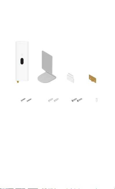
Package Contents
U-LTE Stand Mounting
Self-Tapping Screws
(Qty. 2)
Screw Anchors
(Qty. 2)
Bracket
Machine Screws
(Qty. 2)
Double-Sided
Adhesive
RP-SMA
Cap
System Requirements
• Linux, MacOSX, or Microsoft Windows 7/8/10
• Java Runtime Environment 1.8 or above recommended
• Web Browser: Google Chrome (Other browsers may have
limited functionality)
• UniFi Controller software v5.10 or higher (available at:
downloads.ubnt.com/unifi)
TERMS OF USE: Ubiquiti radio devices must be professionally installed. Shielded Ethernet
cable and earth grounding must be used as conditions of product warranty. TOUGHCable™ is
designed for outdoor installations. It is the professional installer’s responsibility to follow local
country regulations, including operation within legal frequency channels, output power, and
Dynamic Frequency Selection (DFS) requirements.
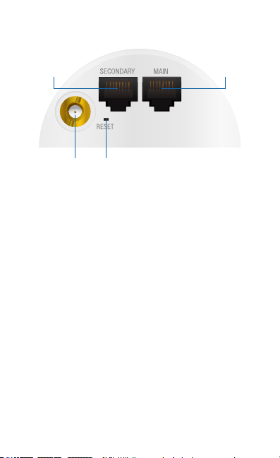
Hardware Overview
Secondary
Reset
RP-SMA
RP-SMA Antenna Connector You can connect an optional
external antenna (not included). If you are not using an
external antenna, then you can cover the connector with the
RP-SMA Cap.
Main
Reset Button The Reset Button serves two functions:
• Restart Press and release the Reset button quickly.
• Restore to Factory Default Settings Press and hold the
Reset button for more than five seconds, until the display
indicates “Factory Reset”.
Secondary This Gigabit Ethernet port is used for bridging and
can provide 24V PoE passthrough to a device.
Main This Gigabit Ethernet port is used to connect the
power and should be connected to the LAN and DHCP server.
24VPassive PoE can be provided by an 802.3at PoE+ switch,
such as a UniFi PoE Switch.
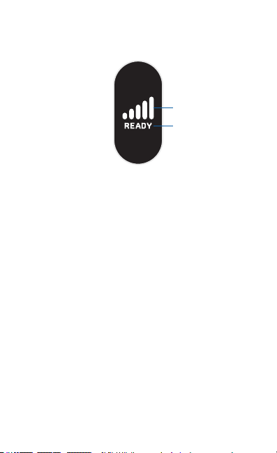
LCD Screen
Status information is displayed.
Signal Strength
Status
Signal Strength Displays the strength of the LTE signal.
Status Displays the device status.

Installation Requirements
• Phillips screwdriver
• Wall-mounting (optional): drill with 6 mm drill bit
• WAN failover: UniFi Security Gateway, model USG or
USG-PRO-4
• UniFi cloud account
• Activation of Ubiquiti LTE data plan
• Free usage for first month with use of SIM activation billing
portal
• For indoor applications, use Category 5 (or above) UTP
cabling approved for indoor use.
• For outdoor applications, shielded Category 5 (or above)
cabling should be used for all wired Ethernet connections
and should be grounded through the AC ground of the
power supply.
We recommend that you protect your networks from
harmful outdoor environments and destructive ESD events
with industrial-grade, shielded Ethernet cable from Ubiquiti
Networks. For more details, visit:
www.ubnt.com/toughcable
WARNING: To reduce the risk of fire or electric shock,
do not expose this product to rain or moisture.
Note: Although the cabling can be located outdoors,
the U-LTE itself should be housed inside a protective
enclosure.
Hardware Installation
The U-LTE can be mounted in three ways:
• Screw Mount
• “Adhesive Mount”
• “Desktop Mount”
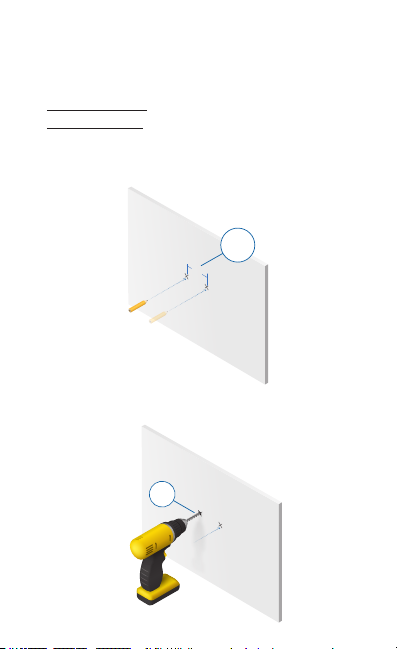
Screw Mount
1. Mark two holes set 22 mm apart.
22 mm
22 mm
2. Drill two holes using a 6 mm drill bit.
6 mm
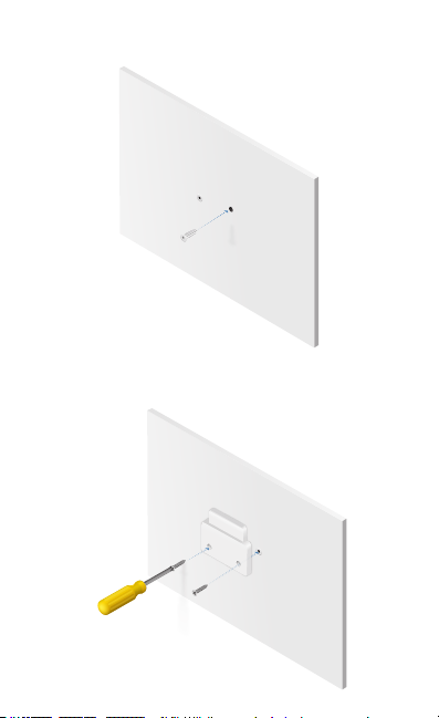
3. Insert a Screw Anchor into each hole.
4. Use the two Self-Tapping Screws to attach the Mounting
Bracket to the wall.
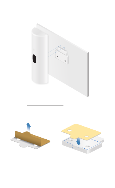
5. Align the Mounting Bracket with the slot on the back of the
U-LTE. Then slide the U-LTE down to lock it into place.
Proceed to “Connecting Ethernet”.
Adhesive Mount
1. Attach the Double-Sided Tape to the Mounting Bracket.
 Loading...