


 Loading...
MERLIN®
PAK® 15XC™
Plasma Cutting System
Instruction Manual
October 6, 1999 |
Manual No. 0-2251 |
Read and understand this entire Instruction Manual and your WARNING employer’s safety practices before installing, operating, or
servicing the equipment.
While the information contained in this Instruction Manual WARNING represents our best judgement, Thermal Dynamics Corporation
assumes no liability for its use.
Merlin PAK 15XC Plasma Cutting System
With PCH/M-150 Torch
Instruction Manual Number 0-2251
Published by:
Thermal Dynamics Corporation Industrial Park No. 2
West Lebanon, New Hampshire, USA 03784 (603) 298-5711
Copyright 1990 by
Thermal Dynamics Corporation
All rights reserved.
Reproduction of this work, in whole or in part, without written permission of the publisher is prohibited.
The publisher does not assume and hereby disclaims any liability to any party for any loss or damage caused by any error or omission in the Merlin PAK 15XC Plasma Cutting System With PCH/M-150 Torch Instruction Manual, whether such error results from negligence, accident, or any other cause.
Printed in the United States of America
October 6, 1999
TABLE OF CONTENTS
SECTION 1: |
|
|
|
GENERAL INFORMATION .................................................................................................. |
1 |
||
1.01 |
Notes, Cautions and Warnings ...................................................................... |
1 |
|
1.02 |
Important Safety Precautions ........................................................................ |
1 |
|
1.03 |
Publications ................................................................................................... |
2 |
|
1.04 |
Note, Attention et Avertissement ................................................................... |
3 |
|
1.05 |
Precautions De Securite Importantes ............................................................ |
3 |
|
1.06 |
Documents De Reference ............................................................................. |
5 |
|
1.07 |
Declaration of Conformity .............................................................................. |
7 |
|
1.08 |
Statement of Warranty ................................................................................... |
8 |
|
SECTION 2: INTRODUCTION & DESCRIPTION ........................................................................ |
9 |
||
2.1 |
SYSTEM DESCRIPTION ................................................................................ |
9 |
|
2.2 |
POWER SUPPLY SPECIFICATIONS ............................................................ |
10 |
|
2.3 |
TORCH SPECIFICATIONS ............................................................................ |
11 |
|
2.4 |
OPTIONS AND ACCESSORIES ................................................................... |
13 |
|
2.5 |
THEORY OF OPERATION ............................................................................ |
14 |
|
SECTION 3: INSTALLATION PROCEDURES ........................................................................... |
17 |
||
3.1 |
UNPACKING THE SYSTEM .......................................................................... |
17 |
|
3.2 |
LOCATION .................................................................................................... |
18 |
|
3.3 |
PLASMA AND SECONDARY CONNECTIONS ............................................. |
18 |
|
3.4 |
ELECTRICAL CONNECTIONS ..................................................................... |
22 |
|
3.5 WORK AND GROUND CONNECTIONS ....................................................... |
24 |
||
3.6 |
COOLANT INSTALLATION............................................................................ |
25 |
|
3.7 |
AUXILIARY CONNECTIONS ......................................................................... |
26 |
|
3.8 |
LIFTING THE POWER SUPPLY .................................................................... |
28 |
|
SECTION 4: OPERATION ......................................................................................................... |
29 |
||
4.1 |
OPERATING CONTROLS ............................................................................. |
29 |
|
4.2 |
PRE-OPERATION SET-UP ............................................................................ |
32 |
|
4.3 |
TORCH PARTS SELECTION ........................................................................ |
33 |
|
4.4 |
GAS SELECTION FOR PLASMA CUTTING ................................................. |
36 |
|
4.5 |
PLASMA CUTTING OPERATION ................................................................. |
40 |
|
4.6 |
HAND TORCH OPERATION ......................................................................... |
44 |
|
4.7 |
MACHINE TORCH OPERATION ................................................................... |
46 |
|
4.8 |
PIERCING ..................................................................................................... |
49 |
|
4.9 |
GOUGING OPERATION ............................................................................... |
50 |
|
4.10 |
COMMON OPERATING ERRORS .............................................................. |
53 |
|
4.11 |
CUTTING SPEEDS ..................................................................................... |
54 |
|
4.12 |
SEQUENCE OF OPERATION ..................................................................... |
61 |
|
|
TABLE OF CONTENTS (continued) |
|
SECTION 5: CUSTOMER/OPERATOR SERVICE ..................................................................... |
63 |
|
5.1 |
TORCH MAINTENANCE ............................................................................... |
63 |
5.2 |
HAND TORCH HEAD REPLACEMENT ........................................................ |
64 |
5.3 |
MACHINE TORCH HEAD REPLACEMENT .................................................. |
66 |
5.4 |
HAND TORCH SWITCH REPLACEMENT .................................................... |
68 |
5.5 |
HAND TORCH LEADS REPLACEMENT ....................................................... |
69 |
5.6 |
MACHINE TORCH LEADS REPLACEMENT ................................................ |
71 |
5.7 |
LEADS EXTENSION KITS - HAND TORCH .................................................. |
73 |
5.8 |
LEADS EXTENSION KITS - MACHINE TORCH ........................................... |
75 |
5.9 |
POWER SUPPLY MAINTENANCE ................................................................ |
78 |
5.10 TROUBLESHOOTING THEORY ................................................................. |
79 |
|
5.11 TROUBLESHOOTING GUIDE ..................................................................... |
83 |
|
5.12 SERVICE AND TEST PROCEDURES ........................................................ |
89 |
|
SECTION 6: PARTS LISTS ........................................................................................................ |
99 |
|
6.1 |
ABOUT THE PARTS LIST ............................................................................. |
99 |
6.2 |
SYSTEM COMPONENTS AND ACCESSORIES ........................................ |
100 |
6.3 |
ACCESS PANEL COMPONENTS ............................................................... |
102 |
6.4 |
FRONT PANEL/CHASSIS COMPONENTS ................................................. |
103 |
6.5 |
REAR PANEL COMPONENTS .................................................................... |
104 |
6.6 |
BASE COMPONENTS ................................................................................ |
106 |
6.7 |
UPPER CHASSIS COMPONENTS ............................................................. |
108 |
6.8 |
MAIN HEATSINK COMPONENTS .............................................................. |
110 |
6.9 |
TORCH COMPONENTS ............................................................................. |
112 |
6.10 TORCH ACCESSORIES ........................................................................... |
114 |
|
APPENDIX I: LADDER DIAGRAM - 120 VAC .......................................................................... |
115 |
|
APPENDIX II: LADDER DIAGRAM - 15 VDC .......................................................................... |
116 |
|
APPENDIX III: DIGITAL CURRENT CONTROL INTERFACE .................................................. |
117 |
|
APPENDIX IV: CNC INTERFACE ............................................................................................ |
118 |
|
APPENDIX V: POWER SUPPLY TO REMOTE CONTROL CABLE INTERFACE .................... |
119 |
|
APPENDIC VI: REMOTE CONTROL CHASSIS SCHEMATIC ................................................. |
120 |
|
APPENDIX VII: RECOMMENDED ROUTINE MAINTENANCE SCHEDULE |
|
|
FOR WATER COOLED PLASMA CUTTING SYSTEMS .................................................. |
121 |
|
APPENDIX VIII: SYSTEM SCHEMATIC .................................................................................. |
122 |
SECTION 1:
GENERAL INFORMATION
1.01 Notes, Cautions and Warnings
Throughout this manual, notes, cautions, and warnings are used to highlight important information. These highlights are categorized as follows:
NOTE
An operation, procedure, or background information which requires additional emphasis or is helpful in efficient operation of the system.
CAUTION
A procedure which, if not properly followed, may cause damage to the equipment.
WARNING
A procedure which, if not properly followed, may cause injury to the operator or others in the operating area.
1.02 Important Safety Precautions
WARNINGS
OPERATION AND MAINTENANCE OF PLASMA ARC EQUIPMENT CAN BE DANGEROUS AND HAZARDOUS TO YOUR HEALTH.
Plasma arc cutting produces intense electric and magnetic emissions that may interfere with the proper function of cardiac pacemakers, hearing aids, or other electronic health equipment. Persons who work near plasma arc cutting applications should consult their medical health professional and the manufacturer of the health equipment to determine whether a hazard exists.
To prevent possible injury, read, understand and follow all warnings, safety precautions and instructions before using the equipment. Call 1-603- 298-5711 or your local distributor if you have any questions.
GASES AND FUMES
Gases and fumes produced during the plasma cutting process can be dangerous and hazardous to your health.
•Keep all fumes and gases from the breathing area. Keep your head out of the welding fume plume.
•Use an air-supplied respirator if ventilation is not adequate to remove all fumes and gases.
•The kinds of fumes and gases from the plasma arc depend on the kind of metal being used, coatings on the metal, and the different processes. You must be very careful when cutting or welding any metals which may contain one or more of the following:
Antimony |
Chromium |
Mercury |
Arsenic |
Cobalt |
Nickel |
Barium |
Copper |
Selenium |
Beryllium |
Lead |
Silver |
Cadmium |
Manganese |
Vanadium |
•Always read the Material Safety Data Sheets (MSDS) that should be supplied with the material you are using. These MSDSs will give you the information regarding the kind and amount of fumes and gases that may be dangerous to your health.
•For information on how to test for fumes and gases in your workplace, refer to item 1 in Subsection 1.03, Publications in this manual.
•Use special equipment, such as water or down draft cutting tables, to capture fumes and gases.
•Do not use the plasma torch in an area where combustible or explosive gases or materials are located.
•Phosgene, a toxic gas, is generated from the vapors of chlorinated solvents and cleansers. Remove all sources of these vapors.
ELECTRIC SHOCK
Electric Shock can injure or kill. The plasma arc process uses and produces high voltage electrical energy. This electric energy can cause severe or fatal shock to the operator or others in the workplace.
•Never touch any parts that are electrically “live” or “hot.”
•Wear dry gloves and clothing. Insulate yourself from the work piece or other parts of the welding circuit.
•Repair or replace all worn or damaged parts.
•Extra care must be taken when the workplace is moist or damp.
Date: 6/22/99 |
1 |
GENERAL INFORMATION |

•Install and maintain equipment according to NEC code, refer to item 9 in Subsection 1.03, Publications.
•Disconnect power source before performing any service or repairs.
•Read and follow all the instructions in the Operating Manual.
FIRE AND EXPLOSION
Fire and explosion can be caused by hot slag, sparks, or the plasma arc.
•Be sure there is no combustible or flammable material in the workplace. Any material that cannot be removed must be protected.
•Ventilate all flammable or explosive vapors from the workplace.
•Do not cut or weld on containers that may have held combustibles.
•Provide a fire watch when working in an area where fire hazards may exist.
•Hydrogen gas may be formed and trapped under aluminum workpieces when they are cut underwater or while using a water table. DO NOT cut aluminum alloys underwater or on a water table unless the hydrogen gas can be eliminated or dissipated. Trapped hydrogen gas that is ignited will cause an explosion.
 NOISE
NOISE
Noise can cause permanent hearing loss. Plasma arc processes can cause noise levels to exceed safe limits. You must protect your ears from loud noise to prevent permanent loss of hearing.
•To protect your hearing from loud noise, wear protective ear plugs and/or ear muffs. Protect others in the workplace.
•Noise levels should be measured to be sure the decibels (sound) do not exceed safe levels.
•For information on how to test for noise, see item 1 in Subsection 1.03, Publications, in this manual.
PLASMA ARC RAYS
Plasma Arc Rays can injure your eyes and burn your skin. The plasma arc process produces very bright ultra violet and infra red light. These arc rays will damage your eyes and burn your skin if you are not properly protected.
•To protect your eyes, always wear a welding helmet or shield. Also always wear safety glasses with side shields, goggles or other protective eye wear.
•Wear welding gloves and suitable clothing to protect your skin from the arc rays and sparks.
•Keep helmet and safety glasses in good condition. Replace lenses when cracked, chipped or dirty.
•Protect others in the work area from the arc rays. Use protective booths, screens or shields.
•Use the shade of lens as suggested in the following per ANSI/ASC Z49.1:
|
Minimum Protective |
Suggested |
Arc Current |
Shade No. |
Shade No. |
Less Than 300* |
8 |
9 |
300 - 400* |
9 |
12 |
400 - 800* |
10 |
14 |
* These values apply where the actual arc is clearly seen. Experience has shown that lighter filters may be used when the arc is hidden by the workpiece.
1.03 Publications
Refer to the following standards or their latest revisions for more information:
1.OSHA, SAFETY AND HEALTH STANDARDS, 29CFR 1910, obtainable from the Superintendent of Documents, U.S. Government Printing Office, Washington, D.C. 20402
2.ANSI Standard Z49.1, SAFETY IN WELDING AND CUTTING, obtainable from the American Welding Society, 550 N.W. LeJeune Rd, Miami, FL 33126
3.NIOSH, SAFETY AND HEALTH IN ARC WELDING AND GAS WELDING AND CUTTING, obtainable from the Superintendent of Documents, U.S. Government Printing Office, Washington, D.C. 20402
4.ANSI Standard Z87.1, SAFE PRACTICES FOR OCCUPATION AND EDUCATIONAL EYE AND FACE PROTECTION, obtainable from American National Standards Institute, 1430 Broadway, New York, NY 10018
5.ANSI Standard Z41.1, STANDARD FOR MEN’S SAFETY-TOE FOOTWEAR, obtainable from the American National Standards Institute, 1430 Broadway, New York, NY 10018
6.ANSI Standard Z49.2, FIRE PREVENTION IN THE USE OF CUTTING AND WELDING PROCESSES, obtainable from American National Standards Institute, 1430 Broadway, New York, NY 10018
7.AWS Standard A6.0, WELDING AND CUTTING CONTAINERS WHICH HAVE HELD COMBUSTIBLES, obtainable from American Welding Society, 550 N.W. LeJeune Rd, Miami, FL 33126
GENERAL INFORMATION |
2 |
Date 6/22/99 |
8.NFPA Standard 51, OXYGEN-FUEL GAS SYSTEMS FOR WELDING, CUTTING AND ALLIED PROCESSES, obtainable from the National Fire Protection Association, Batterymarch Park, Quincy, MA 02269
9.NFPAStandard 70, NATIONAL ELECTRICAL CODE, obtainable from the National Fire Protection Association, Batterymarch Park, Quincy, MA 02269
10.NFPA Standard 51B, CUTTING AND WELDING PROCESSES, obtainable from the National Fire Protection Association, Batterymarch Park, Quincy, MA 02269
11.CGA Pamphlet P-1, SAFE HANDLING OF COMPRESSED GASES IN CYLINDERS, obtainable from the Compressed Gas Association, 1235 Jefferson Davis Highway, Suite 501, Arlington, VA 22202
12.CSA Standard W117.2, CODE FOR SAFETY IN WELDING AND CUTTING, obtainable from the Canadian Standards Association, Standards Sales, 178 Rexdale Boulevard, Rexdale, Ontario, Canada M9W 1R3
13.NWSA booklet, WELDING SAFETY BIBLIOGRAPHY obtainable from the National Welding Supply Association, 1900 Arch Street, Philadelphia, PA 19103
14.American Welding Society Standard AWSF4.1, RECOMMENDED SAFE PRACTICES FOR THE PREPARATION FOR WELDING AND CUTTING OF CONTAINERS AND PIPING THAT HAVE HELD HAZARDOUS SUBSTANCES, obtainable from the American Welding Society, 550 N.W. LeJeune Rd, Miami, FL 33126
15.ANSI Standard Z88.2, PRACTICE FOR RESPIRATORY PROTECTION, obtainable from American National Standards Institute, 1430 Broadway, New York, NY 10018
1.04Note, Attention et Avertissement
Dans ce manuel, les mots “note,” “attention,” et “avertissement” sont utilisés pour mettre en relief des informations à caractère important. Ces mises en relief sont classifiées comme suit :
NOTE
Toute opération, procédure ou renseignement général sur lequel il importe d’insister davantage ou qui contribue à l’efficacité de fonctionnement du système.
ATTENTION
Toute procédure pouvant résulter l’endommagement du matériel en cas de nonrespect de la procédure en question.
AVERTISSEMENT
Toute procédure pouvant provoquer des blessures de l’opérateur ou des autres personnes se trouvant dans la zone de travail en cas de non-respect de la procédure en question.
1.05 Precautions De Securite
Importantes
AVERTISSEMENTS
L’OPÉRATION ET LA MAINTENANCE DU MATÉRIEL DE SOUDAGE À L’ARC AU JET DE PLASMA PEUVENT PRÉSENTER DES RISQUES ET DES DANGERS DE SANTÉ.
Coupant à l’arc au jet de plasma produit de l’énergie électrique haute tension et des émissions magnétique qui peuvent interférer la fonction propre d’un “pacemaker” cardiaque, les appareils auditif, ou autre matériel de santé electronique. Ceux qui travail près d’une application à l’arc au jet de plasma devrait consulter leur membre professionel de médication et le manufacturier de matériel de santé pour déterminer s’il existe des risques de santé.
Il faut communiquer aux opérateurs et au personnel TOUS les dangers possibles. Afin d’éviter les blessures possibles, lisez, comprenez et suivez tous les avertissements, toutes les précautions de sécurité et toutes les consignes avant d’utiliser le matériel. Composez le + 603-298-5711 ou votre distributeur local si vous avez des questions.
FUMÉE et GAZ
La fumée et les gaz produits par le procédé de jet de plasma peuvent présenter des risques et des dangers de santé.
•Eloignez toute fumée et gaz de votre zone de respiration. Gardez votre tête hors de la plume de fumée provenant du chalumeau.
•Utilisez un appareil respiratoire à alimentation en air si l’aération fournie ne permet pas d’éliminer la fumée et les gaz.
Date: 6/22/99 |
3 |
GENERAL INFORMATION |

•Les sortes de gaz et de fumée provenant de l’arc de plasma dépendent du genre de métal utilisé, des revêtements se trouvant sur le métal et des différents procédés. Vous devez prendre soin lorsque vous coupez ou soudez tout métal pouvant contenir un ou plusieurs des éléments suivants:
antimoine |
cadmium |
mercure |
argent |
chrome |
nickel |
arsenic |
cobalt |
plomb |
baryum |
cuivre |
sélénium |
béryllium |
manganèse |
vanadium |
•Lisez toujours les fiches de données sur la sécurité des matières (sigle américain “MSDS”); celles-ci devraient être fournies avec le matériel que vous utilisez. Les MSDS contiennent des renseignements quant à la quantité et la nature de la fumée et des gaz pouvant poser des dangers de santé.
•Pour des informations sur la manière de tester la fumée et les gaz de votre lieu de travail, consultez l’article 1 et les documents cités à la page 5.
•Utilisez un équipement spécial tel que des tables de coupe à débit d’eau ou à courant descendant pour capter la fumée et les gaz.
•N’utilisez pas le chalumeau au jet de plasma dans une zone où se trouvent des matières ou des gaz combustibles ou explosifs.
•Le phosgène, un gaz toxique, est généré par la fumée provenant des solvants et des produits de nettoyage chlorés. Eliminez toute source de telle fumée.
CHOC ELECTRIQUE
Les chocs électriques peuvent blesser ou même tuer. Le procédé au jet de plasma requiert et produit de l’énergie électrique haute tension. Cette énergie électrique peut produire des chocs graves, voire mortels, pour l’opérateur et les autres personnes sur le lieu de travail.
•Ne touchez jamais une pièce “sous tension” ou “vive”; portez des gants et des vêtements secs. Isolez-vous de la pièce de travail ou des autres parties du circuit de soudage.
•Réparez ou remplacez toute pièce usée ou endommagée.
•Prenez des soins particuliers lorsque la zone de travail est humide ou moite.
•Montez et maintenez le matériel conformément au Code électrique national des Etats-Unis. (Voir la page 5, article 9.)
•Débranchez l’alimentation électrique avant tout travail d’entretien ou de réparation.
•Lisez et respectez toutes les consignes du Manuel de consignes.
INCENDIE ET EXPLOSION
Les incendies et les explosions peuvent résulter des scories chaudes, des étincelles ou de l’arc de plasma. Le procédé à l’arc de plasma produit du métal, des étincelles, des scories chaudes pouvant mettre le feu aux matières combustibles ou provoquer l’explosion de fumées inflammables.
•Soyez certain qu’aucune matière combustible ou inflammable ne se trouve sur le lieu de travail. Protégez toute telle matière qu’il est impossible de retirer de la zone de travail.
•Procurez une bonne aération de toutes les fumées inflammables ou explosives.
•Ne coupez pas et ne soudez pas les conteneurs ayant pu renfermer des matières combustibles.
•Prévoyez une veille d’incendie lors de tout travail dans une zone présentant des dangers d’incendie.
•Le gas hydrogène peut se former ou s’accumuler sous les pièces de travail en aluminium lorsqu’elles sont coupées sous l’eau ou sur une table d’eau. NE PAS couper les alliages en aluminium sous l’eau ou sur une table d’eau à moins que le gas hydrogène peut s’échapper ou se dissiper. Le gas hydrogène accumulé explosera si enflammé.
RAYONS D’ARC DE PLASMA
Les rayons provenant de l’arc de plasma peuvent blesser vos yeux et brûler votre peau. Le procédé à l’arc de plasma produit une lumière infra-rouge et des rayons ultra-vio- lets très forts. Ces rayons d’arc nuiront à vos yeux et brûleront votre peau si vous ne vous protégez pas correctement.
•Pour protéger vos yeux, portez toujours un casque ou un écran de soudeur. Portez toujours des lunettes de sécurité munies de parois latérales ou des lunettes de protection ou une autre sorte de protection oculaire.
•Portez des gants de soudeur et un vêtement protecteur approprié pour protéger votre peau contre les étincelles et les rayons de l’arc.
•Maintenez votre casque et vos lunettes de protection en bon état. Remplacez toute lentille sale ou comportant fissure ou rognure.
•Protégez les autres personnes se trouvant sur la zone de travail contre les rayons de l’arc en fournissant des cabines ou des écrans de protection.
GENERAL INFORMATION |
4 |
Date 6/22/99 |

•Utilisez la nuance de lentille qui est suggèrée dans le recommendation qui suivent ANSI/ASC Z49.1:
|
Nuance Minimum |
Nuance Suggerée |
|
Courant Arc |
Protective Numéro |
Numéro |
|
Moins de 300* |
8 |
9 |
|
300 - 400* |
9 |
12 |
|
400 - 800* |
10 |
14 |
|
* Ces valeurs s’appliquent ou l’arc actuel est observé clairement. L’experience a démontrer que les filtres moins foncés peuvent être utilisés quand l’arc est caché par moiceau de travail.
 BRUIT
BRUIT
Le bruit peut provoquer une perte permanente de l’ouïe. Les procédés de soudage à l’arc de plasma peuvent provoquer des niveaux sonores supérieurs aux limites normalement acceptables. Vous dú4ez vous protéger les oreilles contre les bruits forts afin d’éviter une perte permanente de l’ouïe.
•Pour protéger votre ouïe contre les bruits forts, portez des tampons protecteurs et/ou des protections auriculaires. Protégez également les autres personnes se trouvant sur le lieu de travail.
•Il faut mesurer les niveaux sonores afin d’assurer que les décibels (le bruit) ne dépassent pas les niveaux sûrs.
•Pour des renseignements sur la manière de tester le bruit, consultez l’article 1, page 5.
1.06 Documents De Reference
Consultez les normes suivantes ou les révisions les plus récentes ayant été faites à celles-ci pour de plus amples renseignements :
1.OSHA, NORMES DE SÉCURITÉ DU TRAVAIL ET DE PROTECTION DE LA SANTÉ, 29CFR 1910, disponible auprès du Superintendent of Documents, U.S. Government Printing Office, Washington, D.C. 20402
2.Norme ANSI Z49.1, LA SÉCURITÉ DES OPÉRATIONS DE COUPE ET DE SOUDAGE, disponible auprès de la Société Américaine de Soudage (American Welding Society), 550 N.W. LeJeune Rd., Miami, FL 33126
3.NIOSH, LA SÉCURITÉ ET LA SANTÉ LORS DES OPÉRATIONS DE COUPE ET DE SOUDAGE À L’ARC ET AU GAZ, disponible auprès du Superintendent of Documents, U.S. Government Printing Office, Washington, D.C. 20402
4.Norme ANSI Z87.1, PRATIQUES SURES POUR LA PROTECTION DES YEUX ET DU VISAGE AU TRAVAIL ET DANS LES ECOLES, disponible de l’Institut Américain des Normes Nationales (American National Standards Institute), 1430 Broadway, New York, NY 10018
5.Norme ANSI Z41.1, NORMES POUR LES CHAUSSURES PROTECTRICES, disponible auprès de l’American National Standards Institute, 1430 Broadway, New York, NY 10018
6.Norme ANSI Z49.2, PRÉVENTION DES INCENDIES LORS DE L’EMPLOI DE PROCÉDÉS DE COUPE ET DE SOUDAGE, disponible auprès de l’American National Standards Institute, 1430 Broadway, New York, NY 10018
7.Norme A6.0 de l’Association Américaine du Soudage (AWS), LE SOUDAGE ET LA COUPE DE CONTENEURS AYANT RENFERMÉ DES PRODUITS COMBUSTIBLES, disponible auprès de la American Welding Society, 550 N.W. LeJeune Rd., Miami, FL 33126
8.Norme 51 de l’Association Américaine pour la Protection contre les Incendies (NFPA), LES SYSTEMES À GAZ AVEC ALIMENTATION EN OXYGENE POUR LE SOUDAGE, LA COUPE ET LES PROCÉDÉS ASSOCIÉS, disponible auprès de la National Fire Protection Association, Batterymarch Park, Quincy, MA 02269
9.Norme 70 de la NFPA, CODE ELECTRIQUE NATIONAL, disponible auprès de la National Fire Protection Association, Batterymarch Park, Quincy, MA 02269
10.Norme 51B de la NFPA, LES PROCÉDÉS DE COUPE ET DE SOUDAGE, disponible auprès de la National Fire Protection Association, Batterymarch Park, Quincy, MA 02269
11.Brochure GCA P-1, LA MANIPULATION SANS RISQUE DES GAZ COMPRIMÉS EN CYLINDRES, disponible auprès de l’Association des Gaz Comprimés (Compressed Gas Association), 1235 Jefferson Davis Highway, Suite 501, Arlington, VA 22202
12.Norme CSA W117.2, CODE DE SÉCURITÉ POUR LE SOUDAGE ET LA COUPE, disponible auprès de l’Association des Normes Canadiennes, Standards Sales, 178 Rexdale Boulevard, Rexdale, Ontario, Canada, M9W 1R3
13.ivret NWSA, BIBLIOGRAPHIE SUR LASÉCURITÉ DU SOUDAGE, disponible auprès de l’Association Nationale de Fournitures de Soudage (National Welding Supply Association), 1900 Arch Street, Philadelphia, PA 19103
Date: 6/22/99 |
5 |
GENERAL INFORMATION |

14.Norme AWSF4.1 de l’Association Américaine de Soudage, RECOMMANDATIONS DE PRATIQUES SURES POUR LA PRÉPARATION À LA COUPE ET AU SOUDAGE DE CONTENEURS ET TUYAUX AYANT RENFERMÉ DES PRODUITS DANGEREUX , disponible auprès de la American Welding Society, 550 N.W. LeJeune Rd., Miami, FL 33126
15.Norme ANSI Z88.2, PRATIQUES DE PROTECTION RESPIRATOIRE, disponible auprès de l’American National Standards Institute, 1430 Broadway, New York, NY 10018
GENERAL INFORMATION |
6 |
Date 6/22/99 |
1.07 Declaration of Conformity
Manufacturer: Thermal Dynamics Corporation
Address: Industrial Park #2
West Lebanon, New Hampshire 03784
USA
The equipment described in this manual conforms to all applicable aspects and regulations of the ‘Low Voltage Directive’ (European Council Directive 73/23/EEC as amended by Council Directive 93/68/EEC) and to the National legislation for the enforcement of this Directive.
Serial numbers are unique with each individual piece of equipment and details description, parts used to manufacture a unit and date of manufacture.
National Standard and Technical Specifications
The product is designed and manufactured to a number of standards and technical requirements among them are:
*CSA (Canadian Standards Association) standard C22.2 number 60 for Arc welding equipment.
*UL (Underwriters Laboratory) rating 94VO flammability testing for all printed-circuit boards used.
*ISO/IEC 60974-1 (BS 638-PT10) (EN 60 974-1) (EN50192) (EN50078) applicable to plasma cutting equipment and associated accessories.
*Extensive product design verification is conducted at the manufacturing facility as part of the routine design and manufacturing process. This is to ensure the product is safe, when used according to instructions in this manual and related industry standards, and performs as specified. Rigorous testing is incorporated into the manufacturing process to ensure the manufactured product meets or exceeds all design specifications.
Thermal Dynamics has been manufacturing products for more than 30 years, and will continue to achieve excellence in our area of manufacture.
Manufacturers responsible representative: Steve Ward
Director of Operations
Thermadyne UK
Chorley England
Date: 6/22/99 |
7 |
GENERAL INFORMATION |

1.08 Statement of Warranty
LIMITED WARRANTY: Thermal Dynamics® Corporation (hereinafter “Thermal”) warrants that its products will be free of defects in workmanship or material. Should any failure to conform to this warranty appear within the time period applicable to the Thermal products as stated below, Thermal shall, upon notification thereof and substantiation that the product has been stored, installed, operated, and maintained in accordance with Thermal’s specifications, instructions, recommendations and recognized standard industry practice, and not subject to misuse, repair, neglect, alteration, or accident, correct such defects by suitable repair or replacement, at Thermal’s sole option, of any components or parts of the product determined by Thermal to be defective.
THIS WARRANTY IS EXCLUSIVE AND IS IN LIEU OF ANY WARRANTY OF MERCHANTABILITY OR FITNESS FOR A PARTICULAR PURPOSE.
LIMITATION OF LIABILITY: Thermal shall not under any circumstances be liable for special or consequential damages, such as, but not limited to, damage or loss of purchased or replacement goods, or claims of customers of distributor (hereinafter “Purchaser”) for service interruption. The remedies of the Purchaser set forth herein are exclusive and the liability of Thermal with respect to any contract, or anything done in connection therewith such as the performance or breach thereof, or from the manufacture, sale, delivery, resale, or use of any goods covered by or furnished by Thermal whether arising out of contract, negligence, strict tort, or under any warranty, or otherwise, shall not, except as expressly provided herein, exceed the price of the goods upon which such liability is based.
THIS WARRANTY BECOMES INVALID IF REPLACEMENT PARTS OR ACCESSORIES ARE USED WHICH MAY IMPAIR THE SAFETY OR PERFORMANCE OF ANY THERMAL PRODUCT.
THIS WARRANTY IS INVALID IF THE PRODUCT IS SOLD BY NON-AUTHORIZED PERSONS.
The limited warranty periods for Thermal products shall be as follows (with the exception of XL Plus Series, CutMaster 80XL , Cougar and DRAG-GUN): A maximum of three (3) years from date of sale to an authorized distributor and a maximum of two (2) years from date of sale by such distributor to the Purchaser, and with the further limitations on such two (2) year period (see chart below).
The limited warranty period for XL Plus Series and CutMaster 80XL shall be as follows: A maximum of four (4) years from date of sale to an authorized distributor and a maximum of three (3) years from date of sale by such distributor to the Purchaser, and with the further limitations on such three (3) year period (see chart below).
The limited warranty period for Cougar and DRAG-GUN shall be as follows: A maximum of two (2) years from date of sale to an authorized distributor and a maximum of one (1) year from date of sale by such distributor to the Purchaser, and with the further limitations on such two (2) year period (see chart below).
|
|
Parts |
|
|
|
|
|
XL Plus Series & |
Parts |
Parts |
|
||
PAK Units, Power Supplies |
|
CutMaster 80XL |
Cougar/Drag-Gun |
All Others |
Labor |
|
Main Power Magnetics |
|
3 Years |
|
1 Year |
2 Years |
1 Year |
Original Main Power Rectifier |
|
3 Years |
1 Year |
2 Years |
1 Year |
|
Control PC Board |
|
3 Years |
1 Year |
2 Years |
1 Year |
|
All Other Circuits And Components Including, |
|
1 Year |
1 Year |
1 Year |
1 Year |
|
But Not Limited To, Starting Circuit, |
|
|
|
|
|
|
Contactors, Relays, Solenoids, Pumps, |
|
|
|
|
|
|
Power Switching Semi-Conductors |
|
|
|
|
|
|
Consoles, Control Equipment, Heat |
|
1 Year |
|
1 Year |
1 Year |
|
Exchanges, And Accessory Equipment |
|
|
|
|
|
|
Torch And Leads |
|
|
|
|
|
|
Maximizer 300 Torch |
|
|
|
|
1 Year |
1 Year |
All Other Torches |
|
180 Days |
180 Days |
180 Days |
180 Days |
|
Repair/Replacement Parts |
|
90 Days |
90 Days |
90 Days |
None |
|
Warranty repairs or replacement claims under this limited warranty must be submitted by an authorized Thermal Dynamics® repair facility within thirty (30) days of the repair. No transportation costs of any kind will be paid under this warranty. Transportation charges to send products to an authorized warranty repair facility shall be the responsibility of the customer. All returned goods shall be at the customer’s risk and expense. This warranty supersedes all previous Thermal warranties.
Effective May 6, 1999
GENERAL INFORMATION |
8 |
Date 6/22/99 |

SECTION 2: INTRODUCTION & DESCRIPTION
2.1 SYSTEM DESCRIPTION
PAK 15XC Power Supply
Work Cable
Torch Leads
Remote Control Panel
PCM-150 Machine Torch |
A-00875 |
|
Spare Parts Kit
Figure 2-A The Merlin PAK 15XC Plasma Arc Cutting/Gouging System
The Merlin PAK 15XC • PAK 15XC 150 Amp Power Supply
System Includes: with Running Gear and Handle
•PCH-150 90° or 70° Hand Torch
(or) PCM-150 Machine Torch with Mounting Assembly
•25 ft (7.6 m) or 50 ft (15.2 m) Torch Leads
•PCH/M-150 Spare Parts Kit
•25 ft (7.6 m) Work Cable and Clamp
•Running Gear and Handle
•Air Line Filter Assembly (or) High Pressure Regulators
NOTE System options and accessories are listed in Section 2.4.
Manual 0-2251 |
9 |
INTRODUCTION & DESCRIPTION |
2.2 POWER SUPPLY SPECIFICATIONS
Input Power
Output Power
Duty Cycle
Shipping Weight
Voltage |
Frequency |
Phase |
Amperage |
|
|
|
|
200/220/230 |
50 or 60 Hz |
3 |
84/76/73 |
380/415/460 |
50 or 60 Hz |
3 |
44/40/36 |
500/575 |
50 or 60 Hz |
3 |
34/29 |
|
|
|
|
Table 3-A (page 23) contains information on power input, current ratings, circuit protection, and wire sizes.
Continuously adjustable from 50 to 150 amps
100% duty cycle.
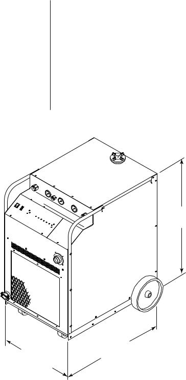
Approximate Shipping Weight - 678 lbs (308 kg)
Enclosure Only:
A-00876
38.38 in
(0.98 m)
|
34.25 in |
|
|
|
24.12 in |
(0.87 m) |
|
|
|
Fully Assembled: |
|
|||
(0.61 m) |
|
|||
Width: |
28.50 in |
(0.72 m) |
||
|
||||
|
Height: |
43.38 in |
(1.10 m) |
|
|
Depth: |
43.75 in |
(1.11 m) |
|
Figure 2-B Power Supply Dimensions
INTRODUCTION & DESCRIPTION |
10 |
Manual 0-2251 |
2.3 TORCH SPECIFICATIONS
Torch Configurations |
|
|
• PCH-150 90° |
Hand Torch |
|
|
|||
|
|
|
• PCH-150 70° |
Hand Torch |
|
|
|||
|
|
|
• PCM-150 Machine Torch |
|
|
||||
Torch Leads Lengths |
|
|
Standard lengths of 25 ft (7.6 m) or 50 ft (15.2 m). |
||||||
|
|
|
Extendable in increments of 25 ft or 50 ft up to a maximum |
||||||
|
|
|
of 150 ft (45.7 m) with available leads extension packages |
||||||
|
|
|
(see Section 2.4, Options and Accessories) |
|
|||||
Current Rating |
|
|
150 Amps Maximum, Direct Current Straight Polarity |
||||||
|
|
|
Hand and Machine Torch rated at 100% Duty Cycle |
||||||
Cutting Range |
|
|
Most materials up to 2.0 in (50.8 mm) |
|
|||||
|
|
|
|
|
|
|
|
|
|
Gas Requirements |
|
|
|
|
|
|
Gases |
Pressure |
Hot Flow * |
|
|
|
|
|
|
|
|
|
|
|
|
|
Plasma |
|
• Compressed Air |
|
For Cutting: |
||
|
|
|
|
• Oxygen (O2) |
50 psi |
22-28 scfh |
|||
|
|
|
|
|
|
• Argon/Hydrogen |
(3.4 BAR, |
(10.4-13.2 lpm) |
|
|
|
|
|
|
|
(Ar/H2) |
340 kPa) |
For Gouging: |
|
|
|
|
|
|
|
• Nitrogen (N2) |
|
22-43 scfh |
|
|
|
|
|
|
|
|
|
|
(10.4-20.3 lpm) |
|
|
|
|
|
|
|
|
|
|
|
|
|
|
|
|
• Compressed Air |
|
For Cutting or |
|
|
|
|
|
|
|
• Nitrogen (N2) |
50 psi |
||
|
|
|
|
|
|
Gouging: |
|||
|
|
|
|
|
|
• Carbon Dioxide |
(3.4 BAR, |
||
|
|
|
Secon- |
|
220 scfh |
||||
|
|
|
|
(CO2) |
340 kPa) |
||||
|
|
|
|
(103 lpm) |
|||||
|
|
|
dary |
|
|
|
|
||
|
|
|
|
|
|
|
|
||
|
|
|
|
|
|
• Water |
Min.50 psi |
8 gph |
|
|
|
|
|
|
|
(3.4 BAR, |
|||
|
|
|
|
|
|
(30.3 lph) |
|||
|
|
|
|
|
|
|
|
340 kPa) |
|
|
|
|
|
|
|
|
|
|
|
NOTE |
|
|
* Hot flow is measured with the main arc activated. When |
||||||
|
|
|
pressure is set correctly the plasma gas flow rate is |
||||||
|
|
|
significantly higher until the arc is initiated. |
||||||
Weight |
|
|
PCH-150 |
90° Hand Torch (without Leads) - 1.0 lb (.45 kg) |
|||||
|
|||||||||
|
|
|
|
|
|
|
|
|
(continued) |
Manual 0-2251 |
11 |
INTRODUCTION & DESCRIPTION |
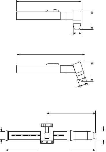
2.3 TORCH SPECIFICATIONS (continued)
PCH-150 90o Hand Torch
13.31 in
(338 mm)
|
3.81 in |
|
(97 mm) |
|
1.62 in |
|
(41 mm) |
|
PCH-150 70o Hand Torch |
|
13.87 in |
|
(352 mm) |
|
3.96 in |
|
(101 mm) |
|
1.62 in |
|
(41 mm) |
|
PCM-150 Machine Torch With Rack |
|
And Pinion Mounting Assembly |
|
6.75 in (171 mm) Min. |
|
16.75 in (425 mm) Max. |
1.38 in |
1.62 in |
(35 mm) |
(41 mm) |
17.65 in (448 mm)
A-02685
Figure 2-C PCH/M-150 Torch Dimensions
INTRODUCTION & DESCRIPTION |
12 |
Manual 0-2251 |

2.4 OPTIONS AND ACCESSORIES
Power Supply Options • Remote Control Panel - For machine torch systems, the and Accessories low profile operator control panel allows system control
from a remote location with 25 or 50 ft (7.6 or 15.2 m) cable included.
•Remote Pendant Control - Hand-held remote contactor control device for machine torch systems.
•Computer Control Cable Kits - For interfacing the power supply with a computer or auxiliary control device. Available in 5 or 10 ft (1.5 or 3.0 m) lengths.
•SC-5 Standoff Control - For machine torch systems, the SC-5 automatically finds height and maintains torch standoff with a high speed torch lifter motor.
•High Pressure Regulators - Available for air, oxygen, argon/hydrogen, nitrogen, CO2, and water.
NOTE See Section 6.2, System Components and Accessories for ordering information.
Torch Options • Spare Parts Kits - Kits contain replacement front-end and Accessories torch parts and tools. Spare parts kits are available for
air cutting with hand or machine torch, multi-gas cutting with hand or machine torch, or for gouging.
•Leads Extension Packages - Available in 25 ft (7.6 m) or 50 ft (15.2 m) lengths. For extending leads up to a maximum of 150 ft (45.7 m).
•Metal Shield Cup - For durability in hand cutting.
NOTE See Section 6.9, Torch Components and Section 6.10, Torch Accessories for ordering information.
Manual 0-2251 |
13 |
INTRODUCTION & DESCRIPTION |
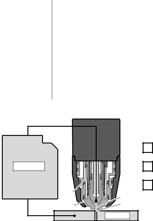
2.5 THEORY OF OPERATION
Plasma Arc Cutting and Plasma is a gas which is heated to an extremely high Gouging temperature and ionized so that it becomes electrically
conductive. The plasma arc cutting process uses this plasma to transfer an electric arc to a workpiece. The metal to be cut is melted by the intense heat of the arc and then blown away. The Merlin PAK 15XC is a high performance plasma cutting system designed to cut most metals up to two inches thick.
With a simple change of torch parts, the system can also be used for plasma arc gouging. Plasma arc gouging is used to remove material to a controlled depth and width.
Plasma Gas Flow The torch uses a cool plasma gas such as compressed air, nitrogen, argon/hydrogen, or oxygen. The plasma gas flows into the torch through the plasma torch lead and is channelled into Zone A (Figure 2-D), where a pilot arc between the torch electrode and tip heats and ionizes the gas. The main cutting arc transfers to the workpiece through the column of plasma gas as it flows out through the torch tip orifice.
(-)
Coolant
Power Supply
|
Plasma Gas |
Zone D |
Secondary Gas |
|
Zone A |
Zone C |
Zone B |
|
|
(+) |
Workpiece |
|
|
|
A-00900 |
Figure 2-D Theory of Operation
INTRODUCTION & DESCRIPTION |
14 |
Manual 0-2251 |

2.5 THEORY OF OPERATION (continued)
Plasma Gas Flow By forcing the plasma gas and arc through a consrticted (continued) orifice, the torch delivers a high concentration of heat to a
small area. The stiff, constricted plasma arc is shown in Zone B (Figure 2-D). Direct current (DC) straight polarity is used for plasma cutting, as shown in the illustration.
Secondary Flow The torch also uses a secondary gas (or water) which assists the high velocity plasma gas in blowing molten metal from the area of the cut to create a fast, slag-free cut. The secondary flow (Zone C, Figure 2-D) also cools the torch and minimizes heat input to the workpiece. The secondary flows into the torch through the secondary lead, down around the outside of the torch liner, and out between the tip and shield cup around the plasma arc. Compressed air, supplied by either a cylinder or plant air system, nitrogen, CO2, or water can be used as the secondary. An exception to this is oxygen plasma operation, which requires no secondary.
Coolant Flow The torch is liquid-cooled by an internal closed cooling system. De-ionized coolant is distributed from a reservoir in the power supply through the coolant supply lead. At the torch, the coolant is circulated around the torch tip and electrode (Zone D, Figure 2-D), where the extra cooling effect helps to increase parts life. The coolant then flows back to the power supply through the return lead.
Pilot Arc When the torch is started, a DC pilot arc is established between the electrode and cutting tip after a two-second pre-flow delay. The pilot arc is initiated by a momentary high frequency pulse. The pilot arc creates a path for the main cutting arc to transfer to the work. When the main arc is established, the pilot arc shuts off. The pilot automatically restarts when the main arc stops, as long as the torch remains activated.
Main Cutting Arc The PAK 15XC accepts 50 or 60 Hz three-phase line input. An internal changeover switches input line voltages in three ranges, for 200/220/230V, 380/415/460V, or 500/ 575V operation. The power supply converts AC input power to DC power for the main cutting arc. The negative output is connected to the torch electrode through the negative torch lead. The positive output is connected to the workpiece via the work cable and clamp connection.
RF Shielding All machine torch systems are shielded to minimize radio frequency (RF) interference which results from the high frequency arc initiation. These shielded systems are designed with features such as a wire for establishing an earth ground and shielded torch and control leads.
Manual 0-2251 |
15 |
INTRODUCTION & DESCRIPTION |

2.5 THEORY OF OPERATION (continued)
Interlocks The system has several built-in interlocks to provide safe and efficient operation. When an interlock shuts down the system, the torch switch (or control device) must be used to restart the system.
Parts-In-Place Interlock The torch has a built-in parts-in-place interlock that prevents accidental torch starting when torch parts are not properly installed. A flow switch on the coolant return lead detects reduced coolant flow caused by improper torch assembly. If not satisfied, the switch interrupts power to the tip and electrode.
Gas Pressure Interlock Pressure switches act as an interlock for the gas supplies. If supply pressure falls below minimum requirements the pressure switches will open, shutting off the power to the contactors, and the GAS indicator will go out. When adequate supply pressure is available the pressure switches close, allowing power to be resumed for cutting.
Thermal Interlock Thermal overload sensors are located in the transformer and main heatsink in the power supply. If one of these components is overheated the appropriate switch will open up, causing the temperature light to turn from green to red and shutting off power to the main contactor. When the overheated component cools down the switch will close again and allow operation of the system.
INTRODUCTION & DESCRIPTION |
16 |
Manual 0-2251 |
SECTION 3: INSTALLATION PROCEDURES
3.1 UNPACKING THE SYSTEM
The power supply is skid-mounted and protected with a carton and padding material to prevent damage during shipment. The power supply, work cable, torch, and torch leads are factory-assembled and packaged together. Also packed with the system are:
•Spare parts kit for the torch
•Coolant de-ionizing cartridge
•Air filter assembly (for air systems)
1.Remove all packing material.
2.Locate the packing list. Use the list to identify and account for each item.
3.Inspect each item for possible shipping damage. If damage is evident, contact your distributor before proceeding with system installation.
The unit is mounted on the skid with two brackets. To remove the unit from the skid, refer to Figure 3-A and:
4.Remove the six bolts connecting the brackets to the base of the unit.
5.Roll the unit off the skid backwards (rear wheels first).
Shipping Brackets |
|
Shipping Pallet |
Three Bolts |
A-00953 |
(Each Side) |
|
Figure 3-A Unpacking the System
Manual 0-2251 |
17 |
INSTALLATION PROCEDURES |

3.2 LOCATION
Choosing the Location
CAUTION
Select a clean, dry location with good ventilation and adequate working space around all components.
The power supply is air cooled and air flow through the front, rear, and side panels must not be obstructed. At least two feet (0.61 m) of clearance should be provided on all sides.
Operation without proper air flow will inhibit proper cooling and reduce duty cycle.
Review Operating Precautions (page iv) to be sure that the selected location meets all safety requirements.
3.3 PLASMA AND SECONDARY CONNECTIONS
Plasma Gas Requirements
Secondary Gas
Requirements
Secondary Water
Requirements
NOTE
CAUTION
Compressed air, oxygen (O2), nitrogen (N2), or argon/ hydrogen (Ar/H2).
Pressure |
50 psi (3.5 BAR) |
|
Flow |
22 - 28 scfh (10.4 |
- 13.2 lpm) For Cutting |
|
22 - 43 scfh (10.4 |
- 20.3 lpm) For Gouging |
|
|
|
Compressed Air, nitrogen (N2), or carbon dioxide (CO2).
Pressure |
50 psi (3.5 BAR) |
|
|
Flow |
220 scfh (103 lpm) For Cutting or Gouging |
|
|
Tap Water |
|
|
|
Pressure |
Min. 50 psi (3.5 BAR) |
|
|
Flow |
8 gph (30.3 lph) For Cutting |
|
|
See Section 4.4, Gas Selection for Plasma Cutting, for detailed information on operation with various plasma and secondary options.
Maximum input gas pressure to the power supply's internal regulator must not exceed 125 psi (8.6 BAR).
INSTALLATION PROCEDURES |
18 |
Manual 0-2251 |
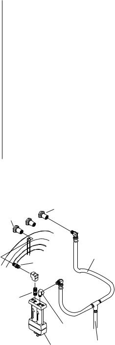
3.3 PLASMA AND SECONDARY CONNECTIONS (continued)
Input Gas Connections
(Air Operation)
Air Line Filter Installation
Systems that are set up for operation with shop air require installation of the air line filter on the plasma input fitting on the rear panel. These systems are shipped with the following components:
(1)Air Line Filter Assembly (For Plasma Line)
(2)Hex Nipples
(1) 90° Female Elbow
(1) 90° Street Elbow
(1) Y-Hose Assembly
Refer to Figure 2-B and:
1.Thread the first hex nipple into the 90° female elbow.
2.Thread the other end of the hex nipple into the outlet of the air filter assembly. Tighten both sides securely.
3.Thread the second hex nipple into the fitting on the rear panel marked PLASMA.
4.Thread the 90° street elbow into the inlet side of the air filter assembly.
(continued)
Secondary Gas
Plasma Gas Fitting
Fitting
Y-Hose
Assembly
Hex Nipple
Female Elbow 
Hex Nipple
Street Elbow |
|
Air Filter Assembly |
From Supply |
|
|
(Plasma Line Only) |
A-00902 |
Figure 3-B Air Line Filter Installation
Manual 0-2251 |
19 |
INSTALLATION PROCEDURES |

3.3 PLASMA AND SECONDARY CONNECTIONS (continued)
Air Line Filter Installation
(continued)
Input Gas Connections
(Multi-Gas Operation)
5.Connect one side of the Y-hose assembly into the other side of the 90° street elbow.
6.Thread the 90° female elbow onto the other end of the second hex nipple. Fasten both sides securely.
7.Connect the other side of the Y-hose assembly to the fitting on the rear panel marked SECONDARY.
8.Connect the supply line from the source to the Y-hose assembly. The supply hose must be 3/8 in (10 mm) min. inside diameter to provide adequate air flow.
1.Examine the cylinder valves to be sure they are clean and free of oil, grease or any foriegn material. Momentarily open each cylinder valve to blow out any dust which may be present.
WARNING Do not stand in front of the valve outlet when opening.
2.Each cylinder must be equipped with an adjustable high-pressure regulator capable of pressures up to 125 psi (8.6 BAR) maximum and flows of up to 220 scfh (103 lpm) for cutting or 470 scfh (222 lpm) for gouging.
CAUTION Maximum input pressure to the power supply's internal regulator must not exceed 125 psi (8.6 BAR).
Refer to the regulator manufacturer's specifications for installation and maintenance procedures. Refer to Section 6.2, System Components and Accessories, for a listing of available high-pressure regulators.
3.Connect the plasma supply hose (black) to the plasma gas cylinder and to the input fitting on the rear panel marked PLASMA.
4.Connect the secondary supply hose (yellow) to the secondary gas cylinder and to the input fitting on the rear panel marked SECONDARY.
NOTE A typical 50 lb. CO2 cylinder can deliver a continuous flow rate of 35 scfh (16.5 lpm). To obtain the required flow rate for the torch, it may be necessary to manifold several CO2 cylinders. Continuous flow requirements will depend on the specific application and duty cycle.
INSTALLATION PROCEDURES |
20 |
Manual 0-2251 |
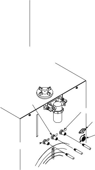
3.3 PLASMA AND SECONDARY CONNECTIONS (continued)
Secondary Water 1. The water source must be capable of delivering a Connections minimum water pressure of 50 psi (3.5 BAR) and flow
of 8 gph (30.3 lph).
2.Connect the secondary water supply hose to the rear panel fitting marked SEC. WATER.
NOTE The water source does not need to be deionized, but in water systems with extremely high mineral content a water softener is recommended.
Secondary Water
Secondary Gas
High Flow
Water Shield
Remote Interface
Connection
Plasma Gas 
A-00874
Figure 3-C Rear Panel Connections
Manual 0-2251 |
21 |
INSTALLATION PROCEDURES |

3.4 ELECTRICAL CONNECTIONS
Electrical Requirements
Electrical Connections
The PAK 15XC power supply is designed to accept a variety of input voltages:
•200/220/230 VAC
•380/415/460 VAC
•500/575 VAC
The electrical power source must conform to local electric code and the following recommended circuit protection and wiring requirements (see Table 3-A).
1.Check the three-phase electrical power source for line voltage and proper circuit protection and wiring (see Table 3-A).
WARNING |
Disconnect primary power at the source before connect- |
|
ing the primary power cable to the power supply. |
||
|
Refer to Figure 3-D and:
2.Remove the left side panel of the power supply (as viewed from the front).
3.Check the bus bar configuration on the input voltage terminal board . The bus bar configuration must correspond with the available line voltage.
4.If necessary, re-position the bus bars to correspond to the available line voltage.
5.Insert the primary power cable through the strain relief in the rear panel of the power supply.
6.Connect the electrical ground wire to the ground lug on the base of the unit.
7.The other three leads attach to terminals L1, L2, and L3 on the input terminal board.
INSTALLATION PROCEDURES |
22 |
Manual 0-2251 |
3.4 ELECTRICAL CONNECTIONS (continued)
Voltage |
Power Input |
Current |
Frequency |
Phase |
Recommended |
||
(Volts) |
(kVA) |
(Amps) |
(Hz) |
|
|
Fuse Size |
Wire Size |
|
|
|
|
|
|
|
|
200 |
29 |
84 |
50 |
3 |
|
90 amps |
AWG 4 |
208 |
29 |
81 |
60 |
3 |
|
90 amps |
AWG 4 |
220 |
29 |
76 |
50 |
3 |
|
90 amps |
AWG 4 |
230 |
29 |
73 |
60 |
3 |
|
90 amps |
AWG 6 |
380 |
29 |
44 |
50 |
3 |
|
50 amps |
AWG 8 |
415 |
29 |
40 |
50 |
3 |
|
45 amps |
AWG 8 |
460 |
29 |
36 |
60 |
3 |
|
40 amps |
AWG 10 |
500 |
29 |
34 |
50 |
3 |
|
40 amps |
AWG 10 |
575 |
29 |
29 |
60 |
3 |
|
35 amps |
AWG 10 |
|
|
|
|
|
|
|
|
Table 3-A Line Voltages, Circuit Protection and Recommended Wire Size (Based on Table 310-16, 1987 National Electric Code).
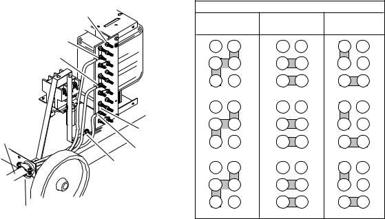
Input Voltage |
Busbar Connections For Input Voltages |
|||
Terminal Board |
||||
200, 208, |
380, 415, |
|
||
|
|
|||
|
220, or 230 |
or 460 |
500, or 575 |
|
|
L3 |
15 |
14 |
15 |
14 |
15 |
14 |
|
L2 |
||||||
|
L3 |
13 |
L3 |
13 |
L3 |
13 |
|
|
|
||||||
|
|
11 |
12 |
11 |
12 |
11 |
12 |
|
|
10 |
9 |
10 |
9 |
10 |
9 |
Primary Power |
Busbars |
L2 |
8 |
L2 |
8 |
L2 |
8 |
|
|
|
|
|
|
||
Cable |
|
|
|
|
|
|
|
|
6 |
7 |
6 |
7 |
6 |
7 |
|
|
|
||||||
|
L1 |
|
|
|
|
|
|
|
Ground |
5 |
4 |
5 |
4 |
5 |
4 |
|
Connection |
L1 |
3 |
L1 |
3 |
L1 |
3 |
|
|
||||||
|
|
1 |
2 |
1 |
2 |
1 |
2 |
Strain Relief |
A-00893 |
Fitting |
A-00904 |
Figure 3-D Input Voltage Connections and Bus Bar Configuration
Manual 0-2251 |
23 |
INSTALLATION PROCEDURES |
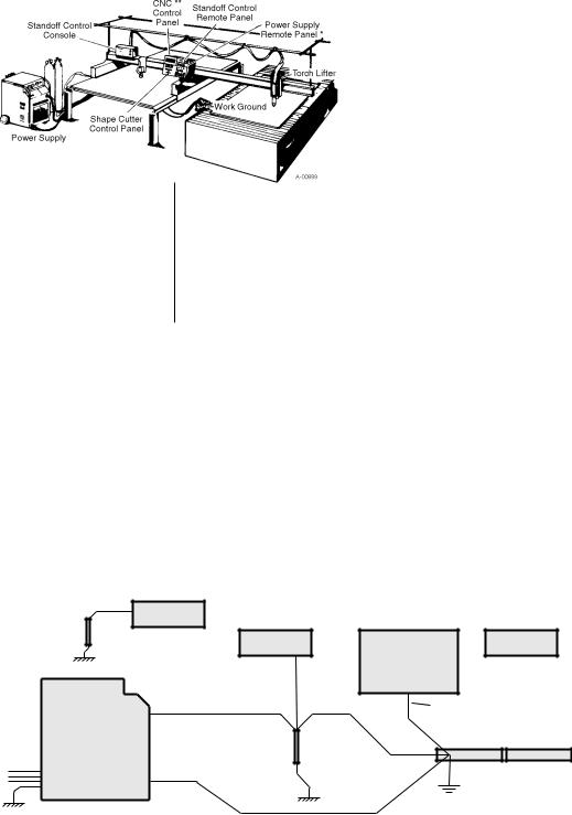
3.5 WORK AND GROUND CONNECTIONS
Machine torch systems are equipped with shielded torch leads to minimize RF interference from high frequency pilot arc initiation. Follow these grounding procedures when installing machine torch systems:
1.Connect the ground wire (from the front panel) to a solid earth ground, which is created by driving a copper rod approximately 7 ft (2 m) into the earth. Locate the rod as close as possible to the power supply. Cut the ground wire to the appropriate length.
2.The power supply and work table should be grounded to the same earth ground. The control device should be grounded separately to a similar earth ground.
3.To minimize RF interference, torch leads should be run as far as possible from any CNC components, control lines, or primary power lines.
4.Connect work ground cables as shown (Figure 3-E).
|
Power Supply |
Standoff Control |
Standoff Control |
Earth |
Remote Panel |
Console |
Remote Panel |
CNC Control |
|
|
|
Ground |
|
|
|
|
|
Green Cable |
|
Power |
|
(Work Ground) |
|
Supply |
Earth |
|
Workpiece |
3-Phase |
|
|
|
Ground |
|
|
|
Input |
|
|
|
|
|
|
|
|
Work |
|
Work Ground |
|
|
|
|
|
Cable |
|
A-00880 |
Figure 3-E Proper Work and Ground Cable Connections
INSTALLATION PROCEDURES |
24 |
Manual 0-2251 |
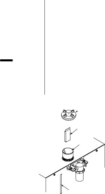
3.6 COOLANT INSTALLATION
Coolant Installation
CAUTION
Refer to Figure 3-F and:
1.Locate the coolant de-ionizing cartridge and remove from the plastic shipping bag.
2.Remove the plastic cover from the coolant reservoir filler.
3.Place the de-ionizing cartridge into the basket in the coolant reservoir.
4.Fill the reservoir to the line marked FULL on the rear panel.
Use only Thermal Arc torch coolant. Use of any other coolant can result in torch damage, insufficient thermal protection, and/or pilot arc interference.
The deionizer cartridge should be checked periodically. The contents of the cartridge take on a light straw-colored appearance when spent. Replace the cartridge when the material has completely changed color.
Coolant Reservoir
 Filler Cap
Deionizer
Bag
Basket
Coolant Level Indicator
A-00872
Figure 3-F Coolant Reservior and De-ionizing Cartridge
Manual 0-2251 |
25 |
INSTALLATION PROCEDURES |
3.7 AUXILIARY CONNECTIONS
Remote Operator Control |
The Remote Operator Control Panel consists of the control |
|
Panel Installation |
panel enclosure and cables required for connection. |
|
|
1. |
Connect the control cable to the receptacle marked |
|
|
REMOTE (J15) on the rear panel. |
|
2. |
Connect the other end of the control cable to the |
|
|
receptacle marked PS (J37) on the remote operator |
|
|
control panel enclosure. |
Computer Control Interface |
1. |
Connect the interface cable to the receptacle marked |
Installation |
|
CNC (J29) on the remote operator control panel. |
|
2. |
Connect the other end to the customer-supplied mo- |
|
|
tion control device (refer to Appendix IV, CNC Inter- |
|
|
face). |
SC-5 Standoff Control |
The SC-5 Standoff Control consists of a control panel, an |
|
Installation |
electronic unit, a voltage divider board, a torch lifter |
|
|
motor, and cables required for installation (refer to Figure |
|
|
3-G). It is ordered and shipped separately and must be |
|
|
installed according to the SC-5 Standoff Control Instruc- |
|
|
tion Manual, which is included with the SC-5 unit. |
|
High-Flow Water Shield |
Refer to the High-Flow Water Shield Instruction Manual |
|
Installation |
and: |
|
|
1. |
Connect the high-flow starter control cable to the |
|
|
receptacle marked HI-FLOW WATER SHIELD on the |
|
|
power supply rear panel. The receptacle is 115VAC to |
|
|
activate the high-flow water shield. |
|
2. |
To shut off the high-flow water shield remove the |
|
|
control cable or disconnect power to the high-flow |
|
|
water shield unit. |
|
|
|
INSTALLATION PROCEDURES |
26 |
Manual 0-2251 |
Loading...