


Troubleshooting Ultracut & Autocut Systems from Status Codes
This is work in progress, do not assume correct or complete
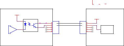
The power supply for these systems is made by another company to TDCs specifications. The rest of the system, the Communications & Control Module (CCM), Remote Arc Starter (RAS), and various gas controls (GCM 1000, GCM 2000, GCM 2010) were designed and are manufactured by TDC.
Because the CCM, which is the “brains” of the system, is mounted into the rear panel of the power supply one might consider it to be part of the power supply however, for this discussion, is it considered a separate part. References to “power supply” or “power supply boards” do not include the CCM.
On start-up and during operation, the power supply control circuitry, along with the CCM, performs various tests. If the circuitry detects a condition requiring operator attention, the CCM causes the Status Indicator on the front panel to flash a 2-part code. First part of the code indicates a code, the second part a particular condition within that group. After 4 seconds the sequence repeats.
Example: Indicator flashes 4 times; the condition is in group 4. After 1.2 seconds delay, the indicator blinks 3 times; the condition code is 4-3, indicating the coolant is overheating or has overheated. After a 4 second delay, the indicator repeats the sequence until the condition is corrected.
The code groups are:
Group 1 Process Codes
Group 2 Power Supply Codes
Group 3 Gas Control Codes
Group 4 Coolant System Codes
Group 5 CANBus Code
Group 6 CCM Fault Codes
Some conditions can be active indefinitely, while others are momentary. Some momentary conditions can shut down the system then they are gone. The power supply and the CCM latch and hold the codes that are set by momentary faults so you can see why the code was set. Most latched codes are cleared by reapplying CNC Start. A few require shutting the power supply off to reset it.
The status indicator may show multiple conditions in sequence; it is important to recognize all possible conditions that may be displayed.
Troubleshooting (General)
A number of the measurements will require probing of some small connectors or measuring signal on ribbon cables. For probing the small connectors, standard meter probes are usually too big. I suggest making a couple probes. Use steel wire copper buss wire that is small enough isn’t stiff enough, it just folds over. One idea is take a socket from an Amp mat-n-loc or similar connector into which your meter probe will fit
1
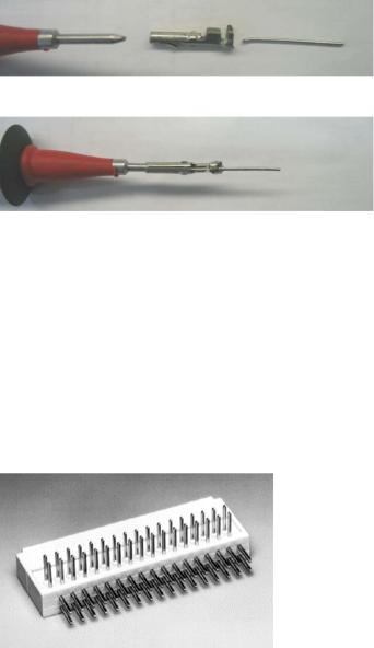
and crimp a small piece of steel wire, 0.020 to 0.025” dia. (0.5-0.6 mm) works best, into where wire would normally be crimped. A paper clip is a little too big.
Insulate all but the end of wire and slide these onto your meter probe.
If your meter has alligator clip adaptors you could hold the wire in these as well, be sure they don’t short together.
Ribbon cable: There are 3 ribbon cables, 16 ckt., 26 ckt. and 34 ckt. For earlier units to measure ribbon cable signals requires test adaptors. For later units we smartened up and included an extra receptacle on the ribbon cable for taking measurements. For the16 ckt. ribbon the extra receptacle is just above the top inverter, for the other two it is next to the ends that connect to the CCM. The home made probes above work will for this.
For earlier units test adapters can be used or buy new style ribbon cables.
I have used these adaptors which are available from Digi-key.
Digi-Key Part Number |
922576-26-ND |
Price Break |
Unit Price |
Price |
|
|
|
1 |
15.45000 |
15.45 |
|
Manufacturer Part Number |
922576-26-I |
||||
|
|
|
|||
|
|||||
Digi-Key Part Number |
922576-34-ND |
Price Break |
Unit Price |
Price |
|
|
|
1 |
17.24000 |
17.24 |
|
Manufacturer Part Number |
922576-34-I |
||||
|
|
|
|||
|
|
|
|
|
|
They do not have one for 16 ckt. But the 20 ckt one can be cut down. Or you can buy a 40 ckt and make two 16’s out of it making each 16 ckt adaptor a little cheaper.
2

Digi-Key Part Number |
922576-20-ND |
Price Break |
Unit Price |
Price |
|
|
|
1 |
14.84000 |
14.84 |
|
Manufacturer Part Number |
922576-20-I |
||||
|
|
|
|||
|
|
||||
Digi-Key Part Number |
922576-40-ND |
Price Break |
Unit Price |
Price |
|
|
|
1 |
18.90000 |
18.90 |
|
Manufacturer Part Number |
922576-40-I |
||||
|
|
|
|||
|
|
|
|
|
|
Power Supply Status Codes Group 1, Process Codes
1-1 E-Stop Activated or Plasma Enable Off
Code 1-1 is activated by either an open circuit between TB1-1&2 (External E- Stop) on CCM I/O PCB or Plasma Enable switched off. 1-1 is not a latched code, it clears as soon as condition is fixed. Plasma Enable switches are on GCM 2010 and GCM2000 gas controls and the Remote HMI.
Causes for 1-1 code (see detailed descriptions below):
•GCM 2010 or GCM 2000 J5 on PCB plugged in wrong.
•Missing one phase of AC Input. Check for 3 phase power at input terminals. Blown fuse, open connection.
•If D21, CNC_E-STOP LED, on CCM I/O board is not illuminated then External E-Stop circuit is not satisfied. Either jumper TB1-1 & 2 (CCM I/O board) is missing or user installed external E-Stop has a fault.
•If D21 is illuminated and D2, E-Stop_PS, is not on then Plasma Enable switch on gas control (GCM 2000, GCM2010) or HMI not on or fault in Plasma enable circuit. See quick test in section on Plasma Enable below.
•If both D21 and D2 are illuminated the CCM is defective.
GCM J5 plugged in wrong interrupts the Plasma Enable circuit. Some gas controls have J5 header which is un-polarized allowing J5 to be reversed. Others have 17 pin header but 16 circuit receptacle. These should be installed so circuits 1-16 are connected leaving pin 17 exposed. If instead, pin 1 is exposed Plasma Enable is interrupted.
Missing phase.
Power to the control circuits comes from two of the 3 input phases. If either of those two are missing there will be enough voltage to the CCM to power its CPU but not the I/O board circuits including the E-Stop. Thus it will falsely detect E- Stop. This condition can be confirmed by measuring the voltage at TP2 to TP1 on the CCM’s I/O PCB (larger of the two boards). Voltage here is normally between 29 to 41 VDC. If a phase is missing it will about half the normal voltage.
If the 3rd phase is missing CCM will receive correct voltage but will correctly signal missing phase. (code 2-1). If missing phase is due to blown fuse check for shorted SCR in inverter(s). See code 2-1 for instructions.
3
External E-Stop
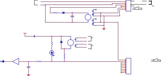
E-Stop input is on CCM module TB1-1&2. This circuit must be closed for normal operation; open activates E-Stop, generating 1-1 code. CCM is supplied from the factory with a jumper across TB1-1&2. The jumper may be replaced with an external switch for remote E-Stop. D21 (CNC E-Stop) on the CCM I/O PCB will light when TB1-1&2 is closed.
If D21 is not on, problem is missing jumper, defective external E-Stop switch or its wiring or the CCM is defective. Note, the CCM is replaced as a unit; individual boards are not replaced separately.
If D21 is on, then Plasma Enable circuit is causing the 1-1 code. K5, E-STOP relay, when off, disables the power supplies power circuits and coolant pump. Also disables the Gas Control preventing gas flow.
Plasma Enable Circuits.
When External E-Stop is satisfied, D21 LED on, relay K3, E-Stop CNC, is closed applying +15VDC to K5’s coil.
HMI is an optional touch screen control panel. When not present, relay K6 on the CCM I/O PCB is not energized connecting J7-1 to gnd. Gas Control’s Plasma Enable Switch, when on (closed), applies gnd, through a relay in the Gas Control, to K5’s coil. D2, E-Stop PS, will illuminate when both external E-Stop and Plasma Enable are satisfied, K5 energized. K5’s contacts, when closed, enable both the gas control and the power supply’s power circuits.
Quick Test
If D2 in the CCM is not illuminated to determine if problem is in CCM or GCM 2000 or 2010 Gas Control (or cables & harness) first disconnect the HMI cable, if present, then jumper J7-1 to J7-2 ( on CCM I/O PCB, the larger board). If D2 comes on problem is in the Gas Control or the control cable. Otherwise it is the CCM.
In the Gas Control if D25 (Plasma Enable LED on the main PCB) is illuminated, jumper J5-6 to J5-7 (connector on main PCB). If D2 on the CCM I/O PCB comes on now the GCM main board is defective. Otherwise problem is In the GCM harness or the control cable.
If D25 (Plasma Enable LED) on the main PCB is not on, jumper J5-1 to J5-1 (connector on main PCB). If D25 still not on main PCB is defective. Otherwise the Plasma Enable switch or its wiring to J5 is bad.
4
J9
24 VAC |
|
|
|
|
24 VAC |
1 |
|
|
|
|
|
||
|
|
24 VAC |
RET |
|
2 |
|
|
|
|
|
|
|
3 |
|
|
|
|
|
|
4 |
|
|
|
4 |
|
|
5 |
150 |
1N4004 |
|
|
|
6 |
|
|
|
|
|
|||
|
1 |
|
2 |
|
|
|
|
|
K6 |
3 |
|
|
|
|
100uF |
5 |
|
|
|
|
|
|
|
|
|
||
|
63V |
|
7 |
|
|
|
|
8 |
|
|
|
|
|
|
|
|
6 |
|
|
|
|
|
|
+15V |
|
|
|
|
|
|
K3 E_STOP CNC |
2 |
K5-E-STOP |
E-STOP |
|
|
|
|
6 |
||
|
|
|
|
+ |
to GAS |
|
|
|
|
|
|
||
|
|
|
|
1N4004 |
5 |
Control |
|
|
|
|
|
||
|
|
|
1.2K |
4 |
|
|
|
|
|
|
|
||
|
|
|
|
|
E-STOP |
|
|
|
|
|
|
3 |
|
|
|
|
|
1 |
to Power |
|
|
|
|
|
DPST |
||
|
|
|
D2 |
|
Supply |
|
|
|
|
|
|
||
|
|
|
E-STOP_ PS |
|
|
|
|
|
|
GREEN |
75.0 |
|
J7 |
|
|
|
|
|
||
To CPU |
|
10 |
9 |
|
|
1 |
|
|
|
2 |
|||
E-Stop |
1N4148 |
|
47K |
|
|
3 |
Input |
|
|
CD4050BC |
|
|
4 |
|
|
|
|
5 |
||
|
|
|
0.1uF |
|
|
6 |
|
|
|
|
|
|
7 |
|
|
|
|
|
|
8 |
|
|
|
|
|
|
9 |
J9 connects 1:1 to J54 HMI Power connector on rear panel of CCM
24 VAC
Power to HMI
Jumper in HMI
PLASMA ENABLE
PLASMA ENABLE
To J55 (GCM) pin 1
To J55 (GCM) pin 2
1-2 Pilot Ignition Failure
Pilot ignition requires both HF from the arcstarter (either the Remote Arcstarter (RAS) or GCM 1000), the pilot contactor on and for units with chopper pilot regulator, enabling the pilot regulator circuit.
Causes for 1-2 code:
•No HF
•Pilot Contactor not closed
•Pilot Regulator (chopper) has no power.
•Pilot Regulator (chopper) not enabled
•No pilot demand to chopper
•Pilot Regulator (chopper) defective
No spark at RAS spark gap
Pilot ignition phase starts at end of pre-flow or immediately after applying Start if system is still in post-flow. If pilot doesn’t ignite within 15 seconds of entering ignition phase, system faults and sets code 1-2.
1.Check that spark gap is set for 0.062” +/- 0.002”. If gap is too high there may not be enough voltage from T1 to fire the gap.
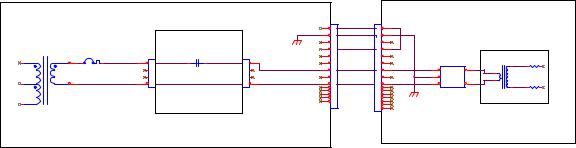
2.120VAC from J59-7 & 9 on the power supply connects to J58- 7 & 9 on the RAS or GCM 1000. From J58 it goes directly to the line filter and passes through the filter to primary of T1. During the ignition phase, for 15 seconds following Preflow, check for 120 VAC on the T1 side of the line filter.
•If 120 VAC not present go to step 3.
•If 120 VAC is present and still no spark, T1 may be bad. Remove power and measure resistance of T1 primary and secondary. T1’s primary should measure about 3-7 ohms. It’s secondary about 25-35 K ohms. If either measurement not correct replace T1.
5
• If T1 measures OK, check for shorted capacitors C1-C3.
3.No 120 VAC to T1 primary during the ignition phase (15 seconds following Preflow) check for 120 VAC into the line filter. It it’s there replace the filter. If not present go to step 4.
4.CCM sends signal HF Enable (active low) at J35-10 to CN10-10 (other end of ribbon cable) on power supply board WK-5602 (PCB5). Signal leaves PCB5, still active low, on CN8-4 and goes to CN8-4 of relay board WK-5628 (PCB7) closing relay RY5. 120 VAC from T1 passes through rear panel circuit breaker CP2 to PCB7’s CN6-1 & 4. RY5 contacts closed sends this 120VAC out on CN7-1 & 4 to rear panel RAS connector J59-7 & 9 to turn on the Arcstarter (RAS or GCM1000).
|
|
|
Ultracut / Autocut |
|
|
J59-RAS J58-RAS |
|
RAS 1000 |
|||
|
|
|
|
|
|
|
|
||||
|
|
|
|
|
|
|
1 |
|
1 |
|
|
|
|
|
|
|
|
|
2 |
KEY PLUG |
2 |
|
|
|
T1 |
|
|
|
|
|
3 |
3 |
|
|
|
|
C.P2 |
CN6 |
RY5 |
CN7 |
|
4 |
|
4 |
|
|
|
|
|
|
|
|
|
|
|||||
|
|
|
5 |
|
5 |
|
|
||||
460 |
|
120. |
AC120V @ 1A 1 |
|
1 |
AC120-RAS |
6 |
|
6 |
|
|
|
|
|
2 |
|
2 |
7 |
|
7 |
Line1 |
Load1 |
|
|
|
|
3 |
|
3 |
0V RAS |
8 |
|
8 |
GND |
|
220 |
|
0___ |
4 |
Part of PCB7 |
4 |
9 |
|
9 |
Line2 |
Load2 |
|
|
|
|
|
|
|
10 |
|
10 |
|
|
|
|
|
|
|
|
|
11 |
|
11 |
Line Filter 1ph |
||
|
|
|
|
|
|
12 |
|
12 |
|||
|
|
|
|
|
|
13 |
|
13 |
|||
0___ |
|
|
|
WK-5628 |
|
|
14 |
|
14 |
|
|
|
|
|
|
|
|
15 |
|
|
|||
|
|
|
|
Relay PCB |
|
|
|
|
16 |
|
|
|
TX1P8S |
|
|
|
|
|
|
|
|
|
|
T1 Assembly
T1 |
3 |
6.8K |
1W |
|
R1 |
||
1 |
|
|
|
2 |
R2 |
6.8K 1W |
|
|
|||
|
4 |
|
|
Pilot Regulator (chopper) Power
Chopper module bias power is high DC voltage supplied to CN5 on the larger of the two chopper PCBs. For all power supplies except 600V, bias power for the chopper comes from P1 (white wire) and N2 (black wire) from top inverter module PCB9 (WK-5605). Voltage will be around 600-700VDC for 400 & 460V inputs and 300-350VDC for 208-230 volt input.
For 600V power supplies the chopper bias comes from a diode D3 mounted to the rear of the T1 transformer. Power to D3 comes from the T1’s 200 VAC primary.
Pilot Enable & Pilot Demand
As soon as CNC Start is applied, CCM makes signal Pilot Enable true (active low) on J35-9. /Pilot Enable goes to PCB5 (WK-5602A) CN10-9 where it turns on relay RY1. 110 VAC from T1 goes to CN9-1. RY1 connects the 110 VAC to CN9-5 to turn on the pilot contactor.
For Chopper Pilot units /Pilot Enable from PCB5 is sent to the Chopper module on CN33-2 (CN33-4 common) to CN2-2 to turn on the chopper. Signal is high, about +15 VDC when not enabled and goes low, nearly zero volts to enable the chopper.
6

For resistor pilot units where the pilot current is controlled by the main inverter, Pilot Enable causes PCB5 to connect Pilot Demand to the inverter signal I_REF. See section on Eagle 100-300 Demand Signals – Cutting & Pilot for troubleshooting.
For Chopper Pilot units Pilot Demand is sent from CN33-3 (CN33-4 common) to CN2-3 chopper. See section on Eagle 100-300 Demand Signals – Cutting & Pilot for troubleshooting.
Pilot Regulator Defective
If chopper has bias power, Pilot Demand and is enabled but still no pilot it may be defective. It can either just not be working or can be shorted.
A quick test is to bypass the chopper. Connect a jumper wire capable of 30A between the pilot busbar (where the pilot lead connects to the power supply) and the anode of D2. Set the output current to 30A to keep the pilot current low.
Pilot |
|
|
Contactor |
|
Jumper |
|
|
|
Chopper |
|
|
|
D2 |
Pilot |
|
Busbar |
|
|
Anode |
|
T1 |
|
|
|
|
Pilot only, DO NOT TRANSFER. If the torch pilots the problem is in the chopper.
More detailed chopper tests.
To test chopper disconnect the cable to the arcstarter at J59 of the power supply rear panel. Connect voltmeter between busbars under the cover on the rear panel where the Torch (negative) and Pilot (positive) leads connect. Attempt to start the unit. If voltage is equal to OCV (open circuit voltage), around 300400VDC, chopper is either working or shorted. If voltage is about ½ the OCV chopper is not working.
Test for shorted chopper.
•First turn off input power and jumper across diode D2 (mounted on the chassis to the rear of the chopper). Leave jumper on for a couple minutes to insure chopper capacitors bleed down to zero volts.
•Chopper freewheel diodes. Measure resistance between TB2 and TB4 on chopper. Expect to see over 20K ohms with it slowly increasing as it
7
charges a capacitor. If using a meter with a diode scale, expect to see continuity one way (diode forward biased) and open with probes reversed. A low resistance with either method indicates a short.
•Chopper IGBTs. Measure resistance TB1 to TB4 on chopper. Should be open circuit. . If using a meter with a diode scale expect to see continuity one way (diode forward biased) and open with probes reversed. A low resistance with either method indicates a short.
1-3 Pilot Out
Pilot has ignited as sensed by Pilot On signal, but went out on its own before the timeout (85 ms. or 3 sec.).
Possible causes:
•Preflow pressure too high, check cut charts for proper setting.
•Cutting current set too low for the torch parts being used. Pilot current level is automatically set based on the cutting current. A low cutting current results in a lower pilot current that may not be able to sustain a pilot for higher current torch parts.
•Remote Analog Current Control switches set wrong can also result in lower than normal pilot current setting. See section on these switch settings under next section for code 1-4.
•Pilot Regulator (Chopper) Defective, refer to previous section 1-2 for quick test to see if chopper is defective.
•Defective Inverter module. The inverter modules supply the power for the pilot while the pilot regulator (chopper) regulates its current. For power supplies with 2 or 3 inverters (150A, 200A or 300A), each inverter supplies a portion of that power. If one inverter is not working it may be enough to start a pilot but not to maintain it thus code 1-3, pilot out early.
o To determine if one inverter is not working, first disconnect the arcstarter cable so the pilot won’t try to start and there will be no HF.
o Disconnect the 16 circuit ribbon cable from all but one of the inverters (CN6 on inverter PCB13). Prepare to measure DCV approximately 300-400VDC between the torch (-) busbar connection and the Work (+) busbar.
o Apply CNC Start, voltage should immediately be present and stay on for about 15 seconds. After 15 seconds you will get a 1-2 code but that is normal because with no HF the pilot can’t ignite. If voltage is present repeat the test with each of the other inverters. Any inverter that the voltage doesn’t appear is defective.
1-4 Loss of Transfer
Arc transferred to metal for at least 50 ms. then went out.
8
Causes for 1-4 code:
•Cut demand set much lower than recommended for torch parts, i.e. 100A consumables in torch but cut current set for 30 or 50A (or zero). Current may be too low to keep arc on.
•Torch standoff too high for cutting process being used.
•Preflow gas flow to low due to a leak somewhere between the preflow regulator and the torch? Check for leaks.
•Remote analog current control switches set wrong.
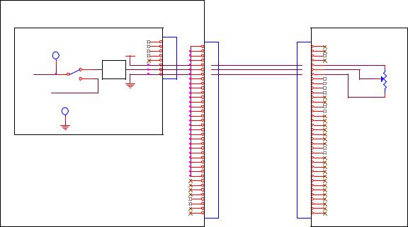
If remote analog current control is being used (SW8-2 (CCM CPU PCB) is on and SW11 (CCM I/O PCB) is set to “A” (down) position) but no analog voltage connected to TB1-10, then cut demand will be zero, pilot will be weak, depending on torch height it may still transfer but will immediately go out.
If remote analog current control is not being used but either SW11 is set to “A” or SW8-2 is on also results in zero cut demand.
If system is Autocut with GCM 1000, current control is analog voltage from the GCM 1000 front panel pot.
SW8-2 should be off and SW11 set to “B” (up) position. With pot at max, check for 3.3V on CCM I/O PCB TP9 (TP1 common). While turning pot toward min TP9 voltage should vary linearly to zero V.
POWER SUPPLY |
|
|
||
CCM |
|
|
J7 |
|
|
|
1 |
||
|
|
|
||
|
TP9 |
|
2 |
|
|
+10VDC |
3 |
||
|
|
|||
|
|
4 |
||
|
|
|
||
|
|
|
5 |
|
0-3.3V |
SW11 3 |
Divide |
6 |
|
7 |
||||
1 |
||||
|
2 |
by 3 |
8 |
|
|
|
|||
|
SPDT |
|
|
|
|
TP1 |
|
|
|
J55 |
J59 |
|
GCM 1000 |
|
|
|
|
||
1 |
1 |
|
|
|
2 |
2 |
|
|
|
3 |
3 |
|
|
|
4 |
4 |
(8) |
(8) |
1 |
5 |
5 |
(9) |
|
|
6 |
6 |
|
|
|
(10) |
(9) |
|
||
7 |
7 |
|
2 |
|
8 |
8 |
|
|
|
|
|
|
||
9 |
9 |
|
|
|
10 |
10 |
|
|
|
11 |
11 |
|
(10) |
3 |
12 |
12 |
|
|
|
13 |
13 |
|
|
|
14 |
14 |
|
CURRENT CONTROL POT |
|
15 |
15 |
|
||
|
|
|
||
16 |
16 |
|
|
|
17 |
17 |
|
|
|
18 |
18 |
|
|
|
19 |
19 |
|
|
|
20 |
20 |
|
|
|
21 |
21 |
|
|
|
22 |
22 |
|
|
|
23 |
23 |
|
|
|
24 |
24 |
|
|
|
25 |
25 |
|
|
|
26 |
26 |
|
|
|
27 |
27 |
|
|
|
28 |
28 |
|
|
|
29 |
29 |
|
|
|
30 |
30 |
|
|
|
31 |
31 |
|
|
|
32 |
32 |
|
|
|
33 |
33 |
|
|
|
34 |
34 |
|
|
|
35 |
35 |
|
|
|
36 |
36 |
|
|
|
37 |
37 |
|
|
|
9
1-5 Off the Plate (software not currently implemented)
Off the Plate feature, when activated (CCM CPU board’s SW5-2 on), detects rapid rise in voltage when torch runs out of metal and cuts the arc off to prevent bending and stretching the arc too far which can damage the torch parts. Status code 1-5 is not a fault but instead indicates Off the Plate has functioned.
1-6 Transfer Timeout
Pilot time is limited to either 85 ms. CCM SW8-1 off (default for pierce starting) or 3 seconds SW8-1 on (used for cutting over holes, expanded metal, etc.). Arc must transfer before pilot time ends. Code 1-6 set if no arc transfer (current in work lead) was sensed before pilot timed out.
Causes for 1-6 code:
•Torch too far from work,
•Cut current set too low for torch parts being used. Pilot current is set based on cut current. If cut current is too low pilot current will be lower and may not transfer at the height used for higher current consumables.
•Preflow pressure/flow too low.
•Remote Analog Current Control switches set wrong can also result in lower than normal pilot current setting. See section on these switch settings under section for code 1-4.
1-7 Tip Saver
Tip saver circuit is not currently implemented.
1-8 Possible Shorted Torch
CCM measures both electrode and tip voltage. If, while cutting, tip voltage rises to within 30V of the electrode voltage CCM shuts off cut and sets 1-8 code. Causes for 1-8 code:
•Gas Flow/pressure too low for consumable parts being used.
oIf gas source pressure is not well regulated it is possible pressure may be OK at times and drop too low at other times such as during a cut.
•Cut current set too high for consumable parts being used.
•Physically shorted torch body between anode (tip) and cathode (electrode). It is more likely a shorted torch body, depending on the resistance of the short, will set code 2-7 (Unwanted Current) as that is measured prior to starting cut while shorted torch is measured while cutting.
Group 2 codes, Power Supply Codes 2-1 Missing Phase.
System required 3 phase power will not operate on single phase. If phase L2 or L3 missing causes code 1-1 (see code 1-1 explanation). Phase L1 missing sets 2-1 code.
Causes for 2-1 code:
10
•Blown fuse in wall fuse/disconnect box or phase missing from power distribution.
•Loose connection on power cord.
•C.P1 (On/Off SW) defective.
•Shorted inrush SCR in inverter module input rectifier bridge.
•Defective power supply PCB (PCB1, PCB4, PCB5)
•Defective CCM
Missing Phase
The power supply checks for 3 phase voltage at both the power supply input terminals and at D1 (3 phase bridge on horizontal panel behind front panel) coming through C.P1 (front panel On/Off SW). Measure the 3 phases at the input terminals L1-L2; L2-L3; L1-L3. Do not measure from Phase to neutral. On D1 measure the 3 phases on the red, white & black wires coming from the bottom of C.P1. If present at the input terminals but missing at D1 it is likely that C.P1 is bad.
Shorted SCR
When power is first applied the input contactor for one inverter closes momentarily then opens. This keeps repeating a number of times during which code 2-1 will flash. After a while contactor may stay on and you could cut however allowing this to continue can damage the contactor and possibly the rectifier bridge and input capacitors.
When power is first applied the AC input voltage is rectified to DC and allowed to slowly charge the input capacitors through a pair of resistors. Then when the capacitors are fully charged an SCR (part of the input bridge) is turned on connecting the DC directly to the capacitors. With the SCR shorted very high currents, limited only by the line impedance, flow through the rectifier bridge and into the filter capacitors. If you have a missing phase the line voltage drops every time that phase should be supplying voltage. The missing phase detection circuit detects the drop. The high currents caused by no inrush limiting cause the voltage to drop momentarily each time the contactor closes. The missing phase detection circuit interprets this drop as missing phase thus the 2-1 code.
To determine if SCR is shorted, find the inverter module(s) on the left side of the unit. The input bridge is to the left end of the module (rear of unit).
11

R2
+
measure resistance between terminals marked R2 and +. Should measure be hundreds or thousands of ohms. A short will read less than 100 ohms.
Power supply boards
Look on PCB5, WK-5602A, for LED2, Missing Phase, illuminated brightly. When phase is not missing will still be on but not so bright. (Don’t blame me, I didn’t design it.) If not, problem is likely in the CCM but still could be in the output side of PCB5.
PCB4, WK-5604, has signal VACIN derived from rectifying 3 phase input on PCB1 (Refer to simplified schematic in section 2-2). VACIN is normally a 3 phase full wave rectified DC level with little ripple. Looks like this:
Voltage that becomes VACIN comes from PCB1 and
goes to CN2-1 on PCB3 where it is passed directly to PCB4 which is daughter board that plugs into PCB3.
VACIN can be measured on PCB3 (WK-5694) between CN2-1 (+) and PGND at CN2-2 (-). PGND may also be found at CN1-1 which may be easier to use than CN2-2.
Note, CN2 must be connected while taking this measurement.
VACIN should be between 7.7 to 9.5V for 460 VAC or 4.3 to 4.7 V for 208-230 VAC Power. For units with 400V input voltage (CE & CCC units) VACIN ranges from 6.25 to 8.25V. 600V? If a phase is missing it will be somewhat lower.
When a phase is missing VACIN looks like this:
12
When a phase is not missing the optoisolator, PHC2, output transistor is off or open so voltage across CN7-1 & 2 is +15 VDC. When a phase is missing, the opto turns on for the time that VACIN is lower than 2.5 V making the output across CN7-1 & 2 into a string of low going pulses. 


|
|
|
|
PCB4 |
|
|
PCB5 |
|
|
+12VDC |
|
|
|
|
|
|
|
|
|
|
|
|
|
|
|
1 |
PHC2 |
|
CN7 |
CN7 |
+15V |
|
|
4 |
|
||||
|
|
|
|
1 |
1 |
|
|
|
|
|
|
|
|
||
|
- |
|
|
3 |
2 |
2 |
|
|
2 |
|
3 |
3 |
Pulse |
||
|
|
|
|||||
VACIN |
|
|
|
4 |
4 |
||
+ |
|
|
|
Detector |
|||
|
|
|
5 |
5 |
|||
|
|
|
|
|
When L1 phase is missing, the voltage measured across CN7-1 & 2 will be less than 15V, probably around 12 V.
Determining which PCB:
Disconnect CN7 from either PCB5 or PCB4. If 2-1 code still present after restoring power then problem is in PCB5 or the CCM. If code went away then look at PCB1 or PCB4. Also remember bad connections in harness connectors can cause faults too.
PCB1
If 3 phase power of proper voltage is connected to the power supply and VACIN is low or zero PCB1 or connections to it may be defective.
PCB4
If the voltage at CN7-1 & 2 is zero may indicate VACIN is not getting to PCB4 or PCB 4 is defective. Also possible there is a bad connection between PCB4 & PCB5.
PCB5
If voltage across CN7-1 & 2 on PCB5 (same as CN7 on PCB4 unless bad connection) +15V but LED2 on PCB 5 is illuminated then PCB5 is defective.
If LED2 is not illuminated, PCB5 should apply a low signal over the 34 ckt ribbon cable from CN11-12 on PCB5 (common is TP0) to J36-12 (common TP1 on CCM I/O PCB) telling the CCM all 3 phases are present. If J36-12 is not low then PCB5 is defective or the ribbon cable is open.
CCM
If J36-12 is low but code 2-1 is still flashing then CCM is defective.
13
 Loading...