


CutMaster
Table of contents
 Loading...
101
SL100SV
™
CUTMASTER
AUTOMATED
PLASMA CUTTING SYSTEM
PLASMA CUTTING
MACHINE TORCH
Art # A-04611
Operating Manual
Rev. AD.01 Date: April 2, 2007 Manual # 0-4642
Operating Features:

WE APPRECIATE YOUR BUSINESS!
Congratulations on your new Thermal Dynamics product. We are
proud to have you as our customer and will strive to provide you
with the best service and reliability in the industry. This product is
backed by our extensive warranty and world-wide service network.
To locate your nearest distributor or service agency call 1-800426-1888, or visit us on the web at www.thermal-dynamics.com.
This Operating Manual has been designed to instruct you on the
correct use and operation of your Thermal Dynamics product.
Your satisfaction with this product and its safe operation is our
ultimate concern. Therefore please take the time to read the entire
manual, especially the Safety Precautions. They will help you to
avoid potential hazards that may exist when working with this
product.
YOU ARE IN GOOD COMPANY!
The Brand of Choice for Contractors and Fabricators Worldwide.
Thermal Dynamics is a Global Brand of manual and automation
Plasma Cutting Products for Thermadyne Industries Inc.
We distinguish ourselves from our competition through marketleading, dependable products that have stood the test of time.
We pride ourselves on technical innovation, competitive prices,
excellent delivery, superior customer service and technical
support, together with excellence in sales and marketing expertise.
Above all, we are committed to developing technologically
advanced products to achieve a safer working environment within
the welding industry.

W ARNINGS
Read and understand this entire Manual and your employer’s safety practices before installing, operating, or servicing the equipment.
While the information contained in this Manual represents the Manufacturer's best judgement, the
Manufacturer assumes no liability for its use.
Automated Plasma Cutting System
Automated CutMaster™ 101 Power Supply
SL100 / SL100SV Machine Torch
Operating Manual Number 0-4642
Covered under U.S. Patents
Published by:
Thermal Dynamics Corporation
82 Benning Street
West Lebanon, New Hampshire, USA 03784
(603) 298-5711
www.thermal-dynamics.com
© Copyright 2004, 2005, 2006, 2007 by
Thermal Dynamics Corporation
All rights reserved.
Reproduction of this work, in whole or in part, without written permission of the publisher is prohibited.
The publisher does not assume and hereby disclaims any liability to any party for any
loss or damage caused by any error or omission in this Manual, whether such error
results from negligence, accident, or any other cause.
Printed in the United States of America
Publication Date: April 2, 2007
Record the following information for Warranty purposes:
Where Purchased:____________________________________
Purchase Date:_______________________________________
Power Supply Serial #:________________________________
Torch Serial #:________________________________________


TABLE OF CONTENTS
SECTION 1:
GENERAL INFORMATION ................................................................................................ 1-1
1.01 Notes, Cautions and Warnings ...................................................................... 1-1
1.02 Important Safety Precautions ....................................................................... 1-1
1.03 Publications .................................................................................................. 1-3
1.04 Note, Attention et Avertissement .................................................................. 1-3
1.05 Precautions De Securite Importantes ........................................................... 1-4
1.06 Documents De Reference ............................................................................. 1-5
1.07 Declaration of Conformity ............................................................................. 1-7
1.08 Statement of Warranty .................................................................................. 1-8
SECTION 2: SPECIFICATIONS ................................................................................................ 2-1
2.01 Scope of Manual .......................................................................................... 2-1
2.02 Power Supply Specifications ......................................................................... 2-1
2.03 Input Wiring Specifications ........................................................................... 2-2
2.04 Power Supply Features ................................................................................. 2-3
2.05 Power Supply Options and Accessories ....................................................... 2-4
2.06 Torch Specifications ..................................................................................... 2-5
2.07 Torch Options and Accessories .................................................................... 2-6
2.08 Introduction to Plasma .................................................................................. 2-7
SECTION 3: INSTALLATION ..................................................................................................... 3-1
3.01 Unpacking .................................................................................................... 3-1
3.02 Lifting Options .............................................................................................. 3-1
3.03 Primary Input Power Connections ................................................................. 3-2
3.04 Gas Connections .......................................................................................... 3-4
3.05 Torch Connections ........................................................................................ 3-7
3.06 Torch Installation .......................................................................................... 3-9
3.07 Torch Parts Selection................................................................................... 3-10
3.08 Power Supply Connection to SC-11 Standoff Control ................................... 3-11
3.09 Power Supply Connection to Alternate Standoff Control ............................... 3-12
3.10 Automation Interface PC Board Set-up ........................................................ 3-14
3.11 Optional Remote Current Control Harness Installation .................................. 3-15
SECTION 4: OPERATION ......................................................................................................... 4-1
4.01 Product Features .......................................................................................... 4-1
4.02 Preparations For Operating ........................................................................... 4-2
4.03 Selection, Inspection and Replacement of Consumable Torch Parts ............. 4-6
4.04 Cut Quality ................................................................................................... 4-8
4.05 General Cutting Information .......................................................................... 4-9
4.06 Torch Operation ........................................................................................... 4-10
4.07 Cutting Parameters ...................................................................................... 4-12
4.08 Cutting Specifications ..................................................................................4-13
4.09 Cutting Speed Chart: Mild Steel, SL100 Torch with Exposed Tip .................. 4-14
4.10 Cutting Speed Charts: Stainless Steel, SL100 Torch with Exposed Tip ........ 4-15
4.11 Cutting Speed Charts: Aluminum, SL100 Torch with Exposed Tip ................4-16
4.12 Cutting Speed Charts: Mild Steel, SL100 Torch with Shielded Tip ................ 4-17
4.13 Cutting Speed Charts: Stainless Steel, SL100 Torch with Shielded Tip ........ 4-18
4.14 Cutting Speed Charts: Aluminum, SL100 Torch with Shielded Tip ................ 4-19
4.15 Operator's Custom Cutting Speed Charts .................................................... 4-20

TABLE OF CONTENTS (continued)
SECTION 5:
SERVICE .......................................................................................................................... 5-1
5.01 General Maintenance .................................................................................... 5-1
5.02 Common Faults ............................................................................................ 5-5
5.03 Basic Troubleshooting ................................................................................... 5-6
5.04 Advanced Troubleshooting Guide - General Information ............................... 5-11
5.05 Main Input and Internal Power Problems ...................................................... 5-13
5.06 Pilot Arc Problems .......................................................................................5-19
5.07 Main Arc Problems ...................................................................................... 5-24
5.08 Test Procedures........................................................................................... 5-25
5.09 Power Supply Major External Parts Replacement ........................................5-31
5.10 Front Panel Parts Replacement.................................................................... 5-33
5.11 Left Side Internal Parts Replacement .......................................................... 5-35
5.12 Right Side Internal Parts Replacement ........................................................ 5-42
SECTION 6:
PARTS LISTS ................................................................................................................... 6-1
6.01 Introduction ................................................................................................... 6-1
6.02 Ordering Information ..................................................................................... 6-1
6.03 Complete Power Supply Replacement .......................................................... 6-1
6.04 Power Supply Basic Replacement Parts ....................................................... 6-2
6.05 Power Supply Options and Accessories ....................................................... 6-2
6.06 Power Supply Major External Replacement Parts ......................................... 6-3
6.07 Power Supply Front Panel Replacement Parts ............................................. 6-4
6.08 Rear Panel Replacement Parts .................................................................... 6-5
6.09 Power Supply Left Side Internal Replacement Parts .................................... 6-6
6.10 Right Side Internal Replacement Parts ........................................................ 6-8
6.11 Torch Replacement Parts .............................................................................6-10
6.12 Torch Replacement Parts .............................................................................6-12
6.13 Torch Consumables ..................................................................................... 6-14
6.14 Torch Spare Parts Kits .................................................................................6-14
6.15 Complete Torch Assembly Replacement ...................................................... 6-16
6.16 Torch Options & Accessories ...................................................................... 6-16
PATENT INFORMATION ...........................................................................................................6-17
APPENDIX 1: SEQUENCE OF OPERATION
(BLOCK DIAGRAM) .......................................................................................................... A-1
APPENDIX 2: DATA TAG INFORMATION ................................................................................ A-2
APPENDIX 3: MAINTENANCE SCHEDULE ............................................................................. A-3
APPENDIX 4: TORCH PIN - OUT DIAGRAMS.......................................................................... A-4
APPENDIX 5: TORCH CONNECTION DIAGRAMS .................................................................. A-5
APPENDIX 6: CONTROL CABLE PIN - OUT DIAGRAM .......................................................... A-6
APPENDIX 7: INTERFACE PCB SWITCH SETTINGS (MOST COMMON SETTINGS) ............ A-7

TABLE OF CONTENTS (continued)
APPENDIX 8: INTERFACE PCB SWITCH SETTINGS (Division Factors 16-24) ....................... A-8
APPENDIX 9: INTERFACE PCB SWITCH SETTINGS (Division Factors 24-30) ....................... A-9
APPENDIX 10: INTERFACE PCB SWITCH SETTINGS (Division Factors 30-33) ................... A-10
APPENDIX 11: INTERFACE PCB SWITCH SETTINGS (Division Factors 33-36) ................... A-11
APPENDIX 12: INTERFACE PCB SWITCH SETTINGS (Division Factors 36-43) ................... A-12
APPENDIX 13: INTERFACE PCB SWITCH SETTINGS (Division Factors 43-50) ................... A-13
APPENDIX 14: AUTOMATION INTERFACE PC BOARD WIRING LAYOUT ............................ A-14
APPENDIX 15: AUTOMATION INTERFACE PC BOARD LAYOUT and TEST POINTS ........... A-15
APPENDIX 16: AUTOMATION INTERFACE PC BOARD WIRING CONNECTIONS TO
OEM CNC HARNESS .................................................................................................... A-16
APPENDIX 17: AUTOMATION INTERFACE PC BOARD WIRING CONNECTIONS TO
ALTERNATE CNC HARNESS .......................................................................................... A-17
APPENDIX 18: MAIN PC BOARD LAYOUT ............................................................................ A-18
APPENDIX 19: MAIN PC BOARD WIRING LAYOUT (208 /230-Volt POWER SUPPLIES) ...... A-20
APPENDIX 20: MAIN PC BOARD WIRING LAYOUT (400-Volt, 415-Volt, 460-Volt,
600-Volt POWER SUPPLIES) ......................................................................................... A-21
APPENDIX 21: LOGIC BOARD LAYOUT ................................................................................ A-22
APPENDIX 22: POT / LED BOARD LAYOUT .......................................................................... A-23
APPENDIX 23: OUTPUT BOARD WIRING DIAGRAM ............................................................ A-24
APPENDIX 24: OUTPUT DIODE BOARD LAYOUT ................................................................ A-25
APPENDIX 25: PILOT BOARD LAYOUT ................................................................................. A-26
APPENDIX 26: 28VAC CIRCUIT DIAGRAM ........................................................................... A-27
APPENDIX 27: INPUT DIODE LAYOUT.................................................................................. A-28
APPENDIX 28: 208/230V SYSTEM SCHEMATIC ................................................................... A-30
APPENDIX 29: 208/230V SYSTEM SCHEMATIC ................................................................... A-32
APPENDIX 30: 400 / 415V / 460V SYSTEM SCHEMATIC ..................................................... A-34

TABLE OF CONTENTS (continued)
APPENDIX 31: 400 / 415V / 460V SYSTEM SCHEMATIC ..................................................... A-36
APPENDIX 32: 600V SYSTEM SCHEMATIC ........................................................................... A-38
APPENDIX 33: 600V SYSTEM SCHEMATIC ........................................................................... A-40
APPENDIX 34: Publication History .......................................................................................... A-42
Global Customer Service Contact Information ..................................................... Inside Rear Cover
SECTION 1:
GENERAL INFORMATION
1.01 Notes, Cautions and Warnings
Throughout this manual, notes, cautions, and warnings
are used to highlight important information. These highlights are categorized as follows:
NOTE
An operation, procedure, or background information which requires additional emphasis or is helpful in efficient operation of the system.
CAUTION
A procedure which, if not properly followed, may
cause damage to the equipment.
WARNING
A procedure which, if not properly followed, may
cause injury to the operator or others in the operating area.
1.02 Important Safety Precautions
WARNINGS
OPERATION AND MAINTENANCE OF
PLASMA ARC EQUIPMENT CAN BE DANGEROUS AND HAZARDOUS TO YOUR
HEALTH.
Plasma arc cutting produces intense electric and
magnetic emissions that may interfere with the
proper function of cardiac pacemakers, hearing
aids, or other electronic health equipment. Persons who work near plasma arc cutting applications should consult their medical health professional and the manufacturer of the health
equipment to determine whether a hazard exists.
GASES AND FUMES
Gases and fumes produced during the plasma cutting process
can be dangerous and hazardous to your health.
• Keep all fumes and gases from the breathing area. Keep
your head out of the welding fume plume.
• Use an air-supplied respirator if ventilation is not adequate to remove all fumes and gases.
• The kinds of fumes and gases from the plasma arc depend on the kind of metal being used, coatings on the
metal, and the different processes. You must be very
careful when cutting or welding any metals which may
contain one or more of the following:
Antimony Chromium M ercury
Arsenic Cobalt Nickel
Barium Copper Selenium
Beryllium Lead Silver
Cadmium Manganese Vanadium
• Always read the Material Safety Data Sheets
(MSDS) that should be supplied with the material
you are using. These MSDSs will give you the information regarding the kind and amount of fumes
and gases that may be dangerous to your health.
• For information on how to test for fumes and gases
in your workplace, refer to item 1 in Subsection 1.03,
Publications in this manual.
• Use special equipment, such as water or down draft
cutting tables, to capture fumes and gases.
• Do not use the plasma torch in an area where combustible or explosive gases or materials are located.
• Phosgene, a toxic gas, is generated from the vapors
of chlorinated solvents and cleansers. Remove all
sources of these vapors.
• This product, when used for welding or cutting,
produces fumes or gases which contain chemicals
known to the State of California to cause birth defects and, in some cases, cancer. (California Health
& Safety Code Sec. 25249.5 et seq.)
To prevent possible injury, read, understand and
follow all warnings, safety precautions and instructions before using the equipment. Call 1-603298-5711 or your local distributor if you have any
questions.
Manual 0-4642 1-1 GENERAL INFORMATION
ELECTRIC SHOCK
NOISE
Electric Shock can injure or kill. The plasma arc process uses
and produces high voltage electrical energy. This electric energy can cause severe or fatal shock to the operator or others
in the workplace.
• Never touch any parts that are electrically “live” or “hot.”
• Wear dry gloves and clothing. Insulate yourself from
the work piece or other parts of the welding circuit.
• Repair or replace all worn or damaged parts.
• Extra care must be taken when the workplace is moist or
damp.
• Install and maintain equipment according to NEC code,
refer to item 9 in Subsection 1.03, Publications.
• Disconnect power source before performing any service
or repairs.
• Read and follow all the instructions in the Operating
Manual.
FIRE AND EXPLOSION
Fire and explosion can be caused by hot slag, sparks, or the
plasma arc.
• Be sure there is no combustible or flammable material in
the workplace. Any material that cannot be removed
must be protected.
• Ventilate all flammable or explosive vapors from the workplace.
• Do not cut or weld on containers that may have held
combustibles.
• Provide a fire watch when working in an area where fire
hazards may exist.
• Hydrogen gas may be formed and trapped under aluminum workpieces when they are cut underwater or while
using a water table. DO NOT cut aluminum alloys underwater or on a water table unless the hydrogen gas
can be eliminated or dissipated. Trapped hydrogen gas
that is ignited will cause an explosion.
Noise can cause permanent hearing loss. Plasma arc processes
can cause noise levels to exceed safe limits. You must protect
your ears from loud noise to prevent permanent loss of hearing.
• To protect your hearing from loud noise, wear protective
ear plugs and/or ear muffs. Protect others in the workplace.
• Noise levels should be measured to be sure the decibels
(sound) do not exceed safe levels.
• For information on how to test for noise, see item 1 in
Subsection 1.03, Publications, in this manual.
PLASMA ARC RAYS
Plasma Arc Rays can injure your eyes and burn your skin. The
plasma arc process produces very bright ultra violet and infra
red light. These arc rays will damage your eyes and burn your
skin if you are not properly protected.
• To protect your eyes, always wear a welding helmet or
shield. Also always wear safety glasses with side shields,
goggles or other protective eye wear.
• Wear welding gloves and suitable clothing to protect
your skin from the arc rays and sparks.
• Keep helmet and safety glasses in good condition. Replace lenses when cracked, chipped or dirty.
• Protect others in the work area from the arc rays. Use
protective booths, screens or shields.
• Use the shade of lens as suggested in the following per
ANSI/ASC Z49.1:
Minimum Protective Suggested
Arc Current Shade No. Shade No.
Less Than 300* 8 9
300 - 400* 9 12
400 - 800* 10 14
* These values apply where the actual arc is
clearly seen. Experience has shown that lighter
filters may be used when the arc is hidden by the
workpiece.
GENERAL INFORMATION 1-2 Manual 0-4642
1.03 Publications
Refer to the following standards or their latest revisions for
more information:
1. OSHA, SAFETY AND HEALTH STANDARDS, 29CFR
1910, obtainable from the Superintendent of Documents,
U.S. Government Printing Office, Washington, D.C. 20402
2. ANSI Standard Z49.1, SAFETY IN WELDING AND CUTTING, obtainable from the American Welding Society, 550
N.W. LeJeune Rd, Miami, FL 33126
3. NIOSH, SAFETY AND HEALTH IN ARC WELDING AND
GAS WELDING AND CUTTING, obtainable from the Superintendent of Documents, U.S. Government Printing Office, Washington, D.C. 20402
4. ANSI Standard Z87.1, SAFE PRACTICES FOR OCCUPATION AND EDUCATIONAL EYE AND FACE PROTECTION, obtainable from American National Standards Institute, 1430 Broadway, New York, NY 10018
5. ANSI Standard Z41.1, STANDARD FOR MEN’S SAFETYTOE FOOTWEAR, obtainable from the American National
Standards Institute, 1430 Broadway, New York, NY 10018
14. American Welding Society Standard AWSF4.1, RECOMMENDED SAFE PRACTICES FOR THE PREPARATION
FOR WELDING AND CUTTING OF CONTAINERS AND
PIPING THAT HAVE HELD HAZARDOUS SUBSTANCES,
obtainable from the American Welding Society, 550 N.W.
LeJeune Rd, Miami, FL 33126
15. ANSI Standard Z88.2, PRACTICE FOR RESPIRATORY
PROTECTION, obtainable from American National Standards Institute, 1430 Broadway, New York, NY 10018
1.04 Note, Attention et
Avertissement
Dans ce manuel, les mots “note,” “attention,” et “avertissement”
sont utilisés pour mettre en relief des informations à caractère
important. Ces mises en relief sont classifiées comme suit :
NOTE
Toute opération, procédure ou renseignement
général sur lequel il importe d’insister davantage
ou qui contribue à l’efficacité de fonctionnement
du système.
6. ANSI Standard Z49.2, FIRE PREVENTION IN THE USE OF
CUTTING AND WELDING PROCESSES, obtainable from
American National Standards Institute, 1430 Broadway, New
York, NY 10018
7. AWS Standard A6.0, WELDING AND CUTTING CONTAINERS WHICH HAVE HELD COMBUSTIBLES, obtainable from American Welding Society, 550 N.W.
LeJeune Rd, Miami, FL 33126
8. NFPA Standard 51, OXYGEN-FUEL GAS SYSTEMS
FOR WELDING, CUTTING AND ALLIED PROCESSES, obtainable from the National Fire Protection
Association, Batterymarch Park, Quincy, MA 02269
9. NFPA Standard 70, NATIONAL ELECTRICAL CODE,
obtainable from the National Fire Protection Association, Batterymarch Park, Quincy, MA 02269
10. NFPA Standard 51B, CUTTING AND WELDING PROCESSES, obtainable from the National Fire Protection Association, Batterymarch Park, Quincy, MA 02269
11. CGA Pamphlet P-1, SAFE HANDLING OF COMPRESSED
GASES IN CYLINDERS, obtainable from the Compressed
Gas Association, 1235 Jefferson Davis Highway, Suite 501,
Arlington, VA 22202
ATTENTION
Toute procédure pouvant résulter
l’endommagement du matériel en cas de nonrespect de la procédure en question.
AVERTISSEMENT
Toute procédure pouvant provoquer des blessures
de l’opérateur ou des autres personnes se trouvant
dans la zone de travail en cas de non-respect de la
procédure en question.
12. CSA Standard W117.2, CODE FOR SAFETY IN WELDING
AND CUTTING, obtainable from the Canadian Standards
Association, Standards Sales, 178 Rexdale Boulevard,
Rexdale, Ontario, Canada M9W 1R3
13. NWSA booklet, WELDING SAFETY BIBLIOGRAPHY obtainable from the National Welding Supply Association,
1900 Arch Street, Philadelphia, PA 19103
Manual 0-4642 1-3 GENERAL INFORMATION
1.05 Precautions De Securite Importantes
AVERTISSEMENTS
L’OPÉRATION ET LA MAINTENANCE DU
MATÉRIEL DE SOUDAGE À L’ARC AU JET
DE PLASMA PEUVENT PRÉSENTER DES
RISQUES ET DES DANGERS DE SANTÉ.
Coupant à l’arc au jet de plasma produit de
l’énergie électrique haute tension et des émissions
magnétique qui peuvent interférer la fonction
propre d’un “pacemaker” cardiaque, les appareils
auditif, ou autre matériel de santé electronique.
Ceux qui travail près d’une application à l’arc au
jet de plasma devrait consulter leur membre
professionel de médication et le manufacturier de
matériel de santé pour déterminer s’il existe des
risques de santé.
Il faut communiquer aux opérateurs et au personnel TOUS les dangers possibles. Afin d’éviter les
blessures possibles, lisez, comprenez et suivez tous
les avertissements, toutes les précautions de sécurité
et toutes les consignes avant d’utiliser le matériel.
Composez le + 603-298-5711 ou votre
distributeur local si vous avez des questions.
• Lisez toujours les fiches de données sur la sécurité des
matières (sigle américain “MSDS”); celles-ci devraient être
fournies avec le matériel que vous utilisez. Les MSDS
contiennent des renseignements quant à la quantité et la
nature de la fumée et des gaz pouvant poser des dangers de
santé.
• Pour des informations sur la manière de tester la fumée et
les gaz de votre lieu de travail, consultez l’article 1 et les
documents cités à la page 5.
• Utilisez un équipement spécial tel que des tables de coupe
à débit d’eau ou à courant descendant pour capter la fumée
et les gaz.
• N’utilisez pas le chalumeau au jet de plasma dans une zone
où se trouvent des matières ou des gaz combustibles ou
explosifs.
• Le phosgène, un gaz toxique, est généré par la fumée
provenant des solvants et des produits de nettoyage
chlorés. Eliminez toute source de telle fumée.
• Ce produit, dans le procéder de soudage et de coupe, produit
de la fumée ou des gaz pouvant contenir des éléments
reconnu dans L’état de la Californie, qui peuvent causer
des défauts de naissance et le cancer. (La sécurité de santé
en Californie et la code sécurité Sec. 25249.5 et seq.)
CHOC ELECTRIQUE
FUMÉE et GAZ
La fumée et les gaz produits par le procédé de jet de plasma
peuvent présenter des risques et des dangers de santé.
• Eloignez toute fumée et gaz de votre zone de respiration.
Gardez votre tête hors de la plume de fumée provenant du
chalumeau.
• Utilisez un appareil respiratoire à alimentation en air si
l’aération fournie ne permet pas d’éliminer la fumée et les
gaz.
• Les sortes de gaz et de fumée provenant de l’arc de plasma
dépendent du genre de métal utilisé, des revêtements se
trouvant sur le métal et des différents procédés. Vous devez
prendre soin lorsque vous coupez ou soudez tout métal
pouvant contenir un ou plusieurs des éléments suivants:
antimoine cadmium mercure
argent chrome nickel
arsenic cobalt plomb
baryum cuivre sélénium
béryllium manganèse vanadium
Les chocs électriques peuvent blesser ou même tuer. Le procédé
au jet de plasma requiert et produit de l’énergie électrique haute
tension. Cette énergie électrique peut produire des chocs graves,
voire mortels, pour l’opérateur et les autres personnes sur le
lieu de travail.
• Ne touchez jamais une pièce “sous tension” ou “vive”;
portez des gants et des vêtements secs. Isolez-vous
de la pièce de travail ou des autres parties du circuit
de soudage.
• Réparez ou remplacez toute pièce usée ou
endommagée.
• Prenez des soins particuliers lorsque la zone de travail est humide ou moite.
• Montez et maintenez le matériel conformément au
Code électrique national des Etats-Unis. (Voir la page
5, article 9.)
• Débranchez l’alimentation électrique avant tout travail d’entretien ou de réparation.
• Lisez et respectez toutes les consignes du Manuel de
consignes.
GENERAL INFORMATION 1-4 Manual 0-4642

INCENDIE ET EXPLOSION
Les incendies et les explosions peuvent résulter des scories
chaudes, des étincelles ou de l’arc de plasma. Le procédé
à l’arc de plasma produit du métal, des étincelles, des
scories chaudes pouvant mettre le feu aux matières combustibles ou provoquer l’explosion de fumées
inflammables.
• Soyez certain qu’aucune matière combustible ou inflammable ne se trouve sur le lieu de travail. Protégez
toute telle matière qu’il est impossible de retirer de la
zone de travail.
• Utilisez la nuance de lentille qui est suggèrée dans le recommendation qui suivent ANSI/ASC Z49.1:
Nuance Minimum Nuance Suggerée
Courant Arc Protective Numéro Numéro
Moins de 300* 8 9
300 - 400* 9 12
400 - 800* 10 14
* Ces valeurs s’appliquent ou l’arc actuel est
observé clairement. L’experience a démontrer que
les filtres moins foncés peuvent être utilisés quand
l’arc est caché par moiceau de travail.
• Procurez une bonne aération de toutes les fumées
inflammables ou explosives.
• Ne coupez pas et ne soudez pas les conteneurs ayant
pu renfermer des matières combustibles.
• Prévoyez une veille d’incendie lors de tout travail dans
une zone présentant des dangers d’incendie.
• Le gas hydrogène peut se former ou s’accumuler sous les
pièces de travail en aluminium lorsqu’elles sont coupées
sous l’eau ou sur une table d’eau. NE PAS couper les
alliages en aluminium sous l’eau ou sur une table d’eau à
moins que le gas hydrogène peut s’échapper ou se dissiper.
Le gas hydrogène accumulé explosera si enflammé.
RAYONS D’ARC DE PLASMA
Les rayons provenant de l’arc de plasma peuvent blesser vos
yeux et brûler votre peau. Le procédé à l’arc de plasma produit
une lumière infra-rouge et des rayons ultra-violets très forts.
Ces rayons d’arc nuiront à vos yeux et brûleront votre peau si
vous ne vous protégez pas correctement.
• Pour protéger vos yeux, portez toujours un casque ou un
écran de soudeur. Portez toujours des lunettes de sécurité
munies de parois latérales ou des lunettes de protection ou
une autre sorte de protection oculaire.
• Portez des gants de soudeur et un vêtement protecteur
approprié pour protéger votre peau contre les
étincelles et les rayons de l’arc.
• Maintenez votre casque et vos lunettes de protection
en bon état. Remplacez toute lentille sale ou
comportant fissure ou rognure.
• Protégez les autres personnes se trouvant sur la zone
de travail contre les rayons de l’arc en fournissant des
cabines ou des écrans de protection.
BRUIT
Le bruit peut provoquer une perte permanente de l’ouïe. Les
procédés de soudage à l’arc de plasma peuvent provoquer des
niveaux sonores supérieurs aux limites normalement acceptables.
Vous dúez vous protéger les oreilles contre les bruits forts
afin d’éviter une perte permanente de l’ouïe.
• Pour protéger votre ouïe contre les bruits forts, portez
des tampons protecteurs et/ou des protections
auriculaires. Protégez également les autres personnes
se trouvant sur le lieu de travail.
• Il faut mesurer les niveaux sonores afin d’assurer que
les décibels (le bruit) ne dépassent pas les niveaux sûrs.
• Pour des renseignements sur la manière de tester le
bruit, consultez l’article 1, page 5.
1.06 Documents De Reference
Consultez les normes suivantes ou les révisions les plus
récentes ayant été faites à celles-ci pour de plus amples
renseignements :
1. OSHA, NORMES DE SÉCURITÉ DU TRAVAIL ET DE
PROTECTION DE LA SANTÉ, 29CFR 1910,
disponible auprès du Superintendent of Documents,
U.S. Government Printing Office, Washington, D.C.
20402
2. Norme ANSI Z49.1, LA SÉCURITÉ DES OPÉRATIONS DE
COUPE ET DE SOUDAGE, disponible auprès de la Société
Américaine de Soudage (American Welding Society), 550
N.W. LeJeune Rd., Miami, FL 33126
3. NIOSH, LA SÉCURITÉ ET LA SANTÉ LORS DES
OPÉRATIONS DE COUPE ET DE SOUDAGE À
L’ARC ET AU GAZ, disponible auprès du Superintendent of Documents, U.S. Government Printing
Office, Washington, D.C. 20402
Manual 0-4642 1-5 GENERAL INFORMATION

4. Norme ANSI Z87.1, PRATIQUES SURES POUR LA
PROTECTION DES YEUX ET DU VISAGE AU TRAVAIL ET DANS LES ECOLES, disponible de l’Institut
Américain des Normes Nationales (American National Standards Institute), 1430 Broadway, New
York, NY 10018
5. Norme ANSI Z41.1, NORMES POUR LES
CHAUSSURES PROTECTRICES, disponible auprès
de l’American National Standards Institute, 1430
Broadway, New York, NY 10018
6. Norme ANSI Z49.2, PRÉVENTION DES INCENDIES
LORS DE L’EMPLOI DE PROCÉDÉS DE COUPE ET
DE SOUDAGE, disponible auprès de l’American National Standards Institute, 1430 Broadway, New
York, NY 10018
7. Norme A6.0 de l’Association Américaine du Soudage
(AWS), LE SOUDAGE ET LA COUPE DE CONTENEURS
AYANT RENFERMÉ DES PRODUITS COMBUSTIBLES,
disponible auprès de la American Welding Society, 550
N.W. LeJeune Rd., Miami, FL 33126
8. Norme 51 de l’Association Américaine pour la Protection
contre les Incendies (NFPA), LES SYSTEMES À GAZ
AVEC ALIMENTATION EN OXYGENE POUR LE
SOUDAGE, LA COUPE ET LES PROCÉDÉS ASSOCIÉS,
disponible auprès de la National Fire Protection Association, Batterymarch Park, Quincy, MA 02269
13. Livret NWSA, BIBLIOGRAPHIE SUR LA SÉCURITÉ
DU SOUDAGE, disponible auprès de l’Association
Nationale de Fournitures de Soudage (National Welding Supply Association), 1900 Arch Street, Philadelphia, PA 19103
14. Norme AWSF4.1 de l’Association Américaine de
Soudage, RECOMMANDATIONS DE PRATIQUES
SURES POUR LA PRÉPARATION À LA COUPE ET
AU SOUDAGE DE CONTENEURS ET TUYAUX
AYANT RENFERMÉ DES PRODUITS DANGEREUX ,
disponible auprès de la American Welding Society, 550
N.W. LeJeune Rd., Miami, FL 33126
15. Norme ANSI Z88.2, PRATIQUES DE PROTECTION
RESPIRATOIRE, disponible auprès de l’American National Standards Institute, 1430 Broadway, New York,
NY 10018
9. Norme 70 de la NFPA, CODE ELECTRIQUE NATIONAL,
disponible auprès de la National Fire Protection Association, Batterymarch Park, Quincy, MA 02269
10. Norme 51B de la NFPA, LES PROCÉDÉS DE COUPE ET
DE SOUDAGE, disponible auprès de la National Fire Protection Association, Batterymarch Park, Quincy, MA 02269
11. Brochure GCA P-1, LA MANIPULATION SANS RISQUE
DES GAZ COMPRIMÉS EN CYLINDRES, disponible
auprès de l’Association des Gaz Comprimés (Compressed
Gas Association), 1235 Jefferson Davis Highway, Suite
501, Arlington, VA 22202
12. Norme CSA W117.2, CODE DE SÉCURITÉ POUR LE
SOUDAGE ET LA COUPE, disponible auprès de
l’Association des Normes Canadiennes, Standards Sales,
178 Rexdale Boulevard, Rexdale, Ontario, Canada, M9W
1R3
GENERAL INFORMATION 1-6 Manual 0-4642

1.07 Declaration of Conformity
Manufacturer: Thermal Dynamics Corporation
Address: 82 Benning Street
West Lebanon, New Hampshire 03784
USA
The equipment described in this manual conforms to all applicable aspects and regulations of the ‘Low Voltage Directive’
(European Council Directive 73/23/EEC as amended by Council Directive 93/68/EEC) and to the National legislation for
the enforcement of this Directive.
The equipment described in this manual conforms to all applicable aspects and regulations of the "EMC Directive" (European Council Directive 89/336/EEC) and to the National legislation for the enforcement of this Directive.
Serial numbers are unique with each individual piece of equipment and details description, parts used to manufacture a unit
and date of manufacture.
National Standard and Technical Specifications
The product is designed and manufactured to a number of standards and technical requirements. Among them are:
* CSA (Canadian Standards Association) standard C22.2 number 60 for Arc welding equipment.
* UL (Underwriters Laboratory) rating 94VO flammability testing for all printed-circuit boards used.
* CENELEC EN50199 EMC Product Standard for Arc Welding Equipment.
* ISO/IEC 60974-1 (BS 638-PT10) (EN 60 974-1) (EN50192) (EN50078) applicable to plasma cutting equipment and associ-
ated accessories.
* For environments with increased hazard of electrical shock, Power Supplies bearing the S mark conform to EN50192
when used in conjunction with hand torches with exposed cutting tips, if equipped with properly installed standoff guides.
* Extensive product design verification is conducted at the manufacturing facility as part of the routine design and manufac-
turing process. This is to ensure the product is safe, when used according to instructions in this manual and related
industry standards, and performs as specified. Rigorous testing is incorporated into the manufacturing process to ensure
the manufactured product meets or exceeds all design specifications.
Thermal Dynamics has been manufacturing products for more than 30 years, and will continue to achieve excellence in our
area of manufacture.
Manufacturers responsible representative: Steve Ward
Operations Director
Thermadyne Europe
Europa Building
Chorley N Industrial Park
Chorley, Lancashire,
England PR6 7BX
Manual 0-4642 1-7 GENERAL INFORMATION

1.08 Statement of Warranty
LIMITED WARRANTY: Subject to the terms and conditions established below, Thermal Dynamics® Corporation warrants to the
original retail purchaser that new Thermal Dynamics CUTMASTER™ 1Series plasma cutting systems sold after the effective date of this
warranty are free of defects in material and workmanship. Should any failure to conform to this warranty appear within the applicable
period stated below, Thermal Dynamics Corporation shall, upon notification thereof and substantiation that the product has been stored
operated and maintained in accordance with Thermal Dynamics’ specifications, instructions, recommendations and recognized industry
practice, correct such defects by suitable repair or replacement.
This warranty is exclusive and in lieu of any warranty of merchantability or fitness for a particular purpose.
Thermal Dynamics will repair or replace, at its discretion, any warranted parts or components that fail due to defects in material or workmanship
within the time periods set out below. Thermal Dynamics Corporation must be notified within 30 days of any failure, at which time Thermal
Dynamics Corporation will provide instructions on the warranty procedures to be implemented.
Thermal Dynamics Corporation will honor warranty claims submitted within the warranty periods listed below. All warranty periods
begin on the date of sale of the product to the original retail customer or 1 year after sale to an authorized Thermal Dynamics Distributor.
LIMITED WARRANTY PERIOD
Product
Power Supply Component s
(Parts and Labor)
Torch and Leads
(Parts and Labor)
CUTMASTER™ 51 3 Years 1 Year
CUTMASTER™ 81 3 Years 1 Year
CUTMASTER™ 101 3 Years 1 Year
This warranty does not apply to:
1. Consumable Parts, such as tips, electrodes, shield cups, o - rings, starter cartridges, gas distributors, fuses, filters.
2. Equipment that has been modified by an unauthorized party, improperly installed, improperly operated or misused
based upon industry standards.
In the event of a claim under this warranty, the remedies shall be, at the discretion of Thermal Dynamics Corporation:
1. Repair of the defective product.
2. Replacement of the defective product.
3. Reimbursement of reasonable costs of repair when authorized in advance by Thermal Dynamics.
4. Payment of credit up to the purchase price less reasonable depreciation based on actual use.
These remedies may be authorized by Thermal Dynamics and are FOB West Lebanon, NH or an authorized Thermadyne service station.
Product returned for service is at the owner’s expense and no reimbursement of travel or transportation is authorized.
LIMITATION OF LIABILITY: Thermal Dynamics Corporation shall not under any circumstances be liable for special or consequential
damages such as, but not limited to, damage or loss of purchased or replacement goods or claims of customer of distributors (hereinafter
“Purchaser”) for service interruption. The remedies of the Purchaser set forth herein are exclusive and the liability of Thermal Dynamics
with respect to any contract, or anything done in connection therewith such as the performance or breach thereof, or from the manufacture,
sale, delivery, resale, or use of the goods covered by or furnished by Thermal Dynamics whether arising out of contract, negligence,
strict tort, or under any warranty, or otherwise, shall not, except as expressly provided herein, exceed the price of the goods upon which
liability is based.
This warranty becomes invalid if replacement parts or accessories are used which may impair the safety or performance of any
Thermal Dynamics product.
This warranty is invalid if the Thermal Dynamics product is sold by non - authorized persons.
Effective January 15, 2004
GENERAL INFORMATION 1-8 Manual 0-4642

SECTION 2: SPECIFICATIONS
%60%35%
%
%35%
2.01 Scope of Manual
This manual contains descriptions, operating instructions and basic maintenance procedures for the Thermal Dynamics Automated CutMaster 101 Plasma Cutting System. Servicing of this equipment is restricted to properly trained personnel; unqualified
personnel are strictly cautioned against attempting repairs or adjustments not covered in this manual, at the risk of voiding the
Warranty.
Read this manual thoroughly. A complete understanding of the characteristics and capabilities of this equipment will assure the
dependable operation for which it was designed.
2.02 Power Supply Specifications
Automated CutM aster 101 Power Supply Specifications
208 / 230 VAC (187 - 253 VAC), Single Phase, 50/60 Hz
400 VAC (360 - 440 VAC), Three Phase, 50/60 Hz
400 VAC (360 - 440 VAC), Three Phase, 50 Hz, CE
Input Power
Input Power Cable
Output Current
Power Supply
Gas Filtering Ability
Ambient Temperature
208/230V,
and 460V Units
400V / 415V Units
600V Units
* NOTE: The duty cycle will be reduced if the primary input power (AC) is low
or the output voltage (DC) is higher than shown in this chart.
415 VAC (370 - 460 VAC), Three Phase, 50 Hz, CE
460 VAC (414 - 506 VAC), Single Phase, 60 Hz
460 VAC (414 - 506 VAC), Three Phase, 60 Hz
600 VAC (517 - 632 VAC), Three Phase, 60 hz
Cable for 208/230 VAC unit includes plug.
20 - 80 Amps, Continuously Adjustable
Particulates to 20 Microns
CutMaster 101 Power Supply Duty Cycle *
40° C (104° F)
IEC
Rating
Duty Cyc le
Current 80A 78A 68A 68A 45A 45A
DC Voltage 112V 120V 107V 111V 98V 98V
Duty Cyc le
Current 80A 78A 68A 68A 45A 45A
DC Voltage 112V 120V 107V 111V 98V 98V
Duty Cyc le
Current 80A 78A 68A 68A 43A 43A
DC Voltage 112V 120V 107V 111V 97V 97V
TDC
Rating
40% 60% 100%
IEC
Rating
60
TDC
Rating
IEC
Rating
100
100
TDC
Rating
2
NOTE:
IEC Rating is determined as specified by the International Electro-Technical Commission. These specifications
include calculating an output voltage based upon power supply rated current. To facilitate comparison between
power supplies, all manufacturers use this output voltage to determine duty cycle.
TDC Rating is determined using an output voltage representative of actual output voltage during cutting with a
TDC torch. This voltage may be more or less than IEC voltage, depending upon choice of torch, consumables, and
actual cutting operation.
Manual 0-4642 2-1 INTRODUCTION
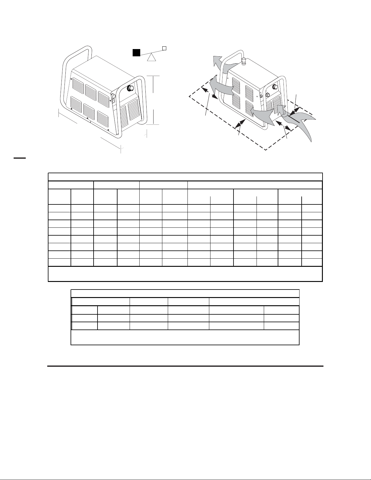
Power Supply Dimensions & Weight Ventilation Clearance Requirements
s
Art # A-03379
83 lb / 37.6 kg
150 mm
17.3 in /
439 mm
6"
27.5 in / 696 mm
12.4 in /
2
A-03572
315 mm
2.03 Input Wiring Specifications
CutMaster 101 Input Wiring Specification
Input Power Input Current Input Suggested Sizes (See Notes)
Voltage Freq. 1-Ph 3-Ph 1-Ph 3-Ph Fuse (Amps) Wire (AWG) Wir e (Canada)
(Volts) (Hz) (kVA) (kVA) (Amps) (Amps) 1-Ph 3-Ph 1-Ph 3-Ph 1-Ph 3-Ph
208 50 14.4 69 90 6 6
208 60 15.6 75 90 6 6
230 50 15 65 80 6 6
230 60 15.5 67 80 6 6
400 50/60 13.9 20 30 10 10
460 60 18 39 50 10 10
460601620301212
600 60 13.5 13 20 12 12
Line Voltages wi th Suggested Circ ui t Protec tion and Wire Si z es
Based on Nati onal Electric Code and Canadian Electri cal Code
24"
0.6 m
6"
150 mm
6"
150 mm
CE CutMaster 101 Input Wiring Specifications
Input Suggested Sizes (See Notes)
Voltage Frequency 3-Ph 3-Ph Fuse (Amps)
Power Input Current Input
Wire (mm
2
)
(Volts) (Hz) (kVA) (Amps) 3-Ph 3-Ph
400 / 415 50 13.9 20 25 4
Line Voltages with Suggested Circuit Protection and Wire Sizes
Based on National Electric Code and Canadian Electric Code
NOTES
Refer to Local and National Codes or local authority having jurisdiction for proper wiring requirements.
Cable size is de-rated based on the Duty Cycle of the equipment.
The suggested sizes are based on flexible power cable with power plug installations. For hard-wired installations
refer to local or national codes.
Cable conductor temperature used is 167° F (75° C).
An energy limiting fuse UL Class RK-1 (examples: BUSS LPS / LPN-RK or Gould-Shawmut AZK-A6K) should be
used to minimize damage to Plasma Cutting, Welding or power distribution equipment.
NEVER use replaceable element fuses like UL Class H, or "one-time" fuses like UL Class K5.
INTRODUCTION 2-2 Manual 0-4642
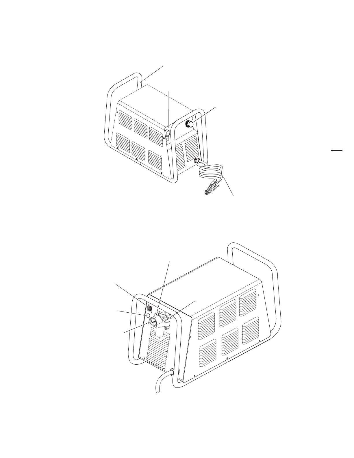
2.04 Power Supply Features
Handle and Leads Wrap
Art # A-04507
Control Panel
Torch Leads Receptacle
2
Work Cable
and Clamp
Gas Pressure Regulator / Filter Assembly
CPC Connector for
Thermal Dynamics CNC Controller
Knockout for Alternate
CNC Controller
Wire Harness
Gas Pressure Gauge
Input Power Cord
Gas Inlet Port
Art # A-04214
Manual 0-4642 2-3 INTRODUCTION

2.05 Power Supply Options and Accessories
Section 6, Parts Lists, provides catalog numbers and ordering information.
A. Single-Stage Air Filter Kit
For use with compressed air shop systems. Filters moisture and particulate matter from the air stream to at least
0.85 microns. This filter increases performance and improves consumables parts life.
B. Two Stage Air Filter Kit
For use on compressed air shop systems. Filters moisture and contaminants from the air stream to at least 5.0
microns. This filter is pre-assembled at the factory and needs only to be installed on the power supply.
C. High Pressure Regulators
High pressure regulators are available. The regulators are used to set the proper compressed air pressure.
2
Regulators should not be installed with In-Line Air Filters.
D. Extended Work Cable with Clamp
As an alternative to the standard 20 ft / 6.1 m work cable & clamp on the power supply, a 50 ft / 15.2 m work cable
with clamp is available.
E. Multi-Purpose Cart
Rugged steel cart on easy-rolling rear wheels and front-mounted swivel casters. Provides maximum mobility for
the power supply and can also serve as a display cart. Top shelf is 12" / 305 mm x 20" / 508 mm. Steel handle is
30" / 762 mm high.
F. Wheel Kit
A kit with easy-rolling wheels, for maximum portability for the power supply.
G. Nylon Dust Cover
Nylon canvas power supply dust cover with water resistant finish, large outer pocket for storing manuals or spare
consumables, and adjustable draw cord for tight fit.
NOTE
INTRODUCTION 2-4 Manual 0-4642
2.06 Torch Specifications
s
s
E
:
E
SL100SV Machine Torch Specifications
Ambient Temperature 104° F / 40° C
Duty Cy c le
Maximum Current 100 Amps
Voltage (V
Arc Striking Voltage 7kV
Type of Cooling
Current Rating Up to 100 Amps, DC, Straight Polarity
Gas (Plasma and Secondary)
Operating Pressure (Varies According to
Power Supply and Torch Leads Length)
Maximum Input Pressure 125 psi / 8.6 bar
Gas Flow
NOT
Thermal Dynamics CutMaster 51, CutMaster 81, CutMaster 101, CutMaster 151
(Refer to NOTE)
) 500V
p eak
: Operating pressure varies with operating amperage and torch leads length.
Torch duty cycle is greater than power supply duty cycle.
Torch Ratings
100% @ 100 Amps @ 400 scfh
Combination of Ambient Air and
Gas Flow Through Torc h
Gas Requirement
Compressed Air (
300 - 500 scfh / 142 - 235 lpm
Torch Leads Length
25' / 7.6 m, with ATC Connector
35' / 10.6 m, with ATC Connector
50' / 15.2 m, with ATC Connector
Plasma Power Supply Used With
NOT
60 - 75 psi
4.1 - 5.2 bar
ONLY
)
2
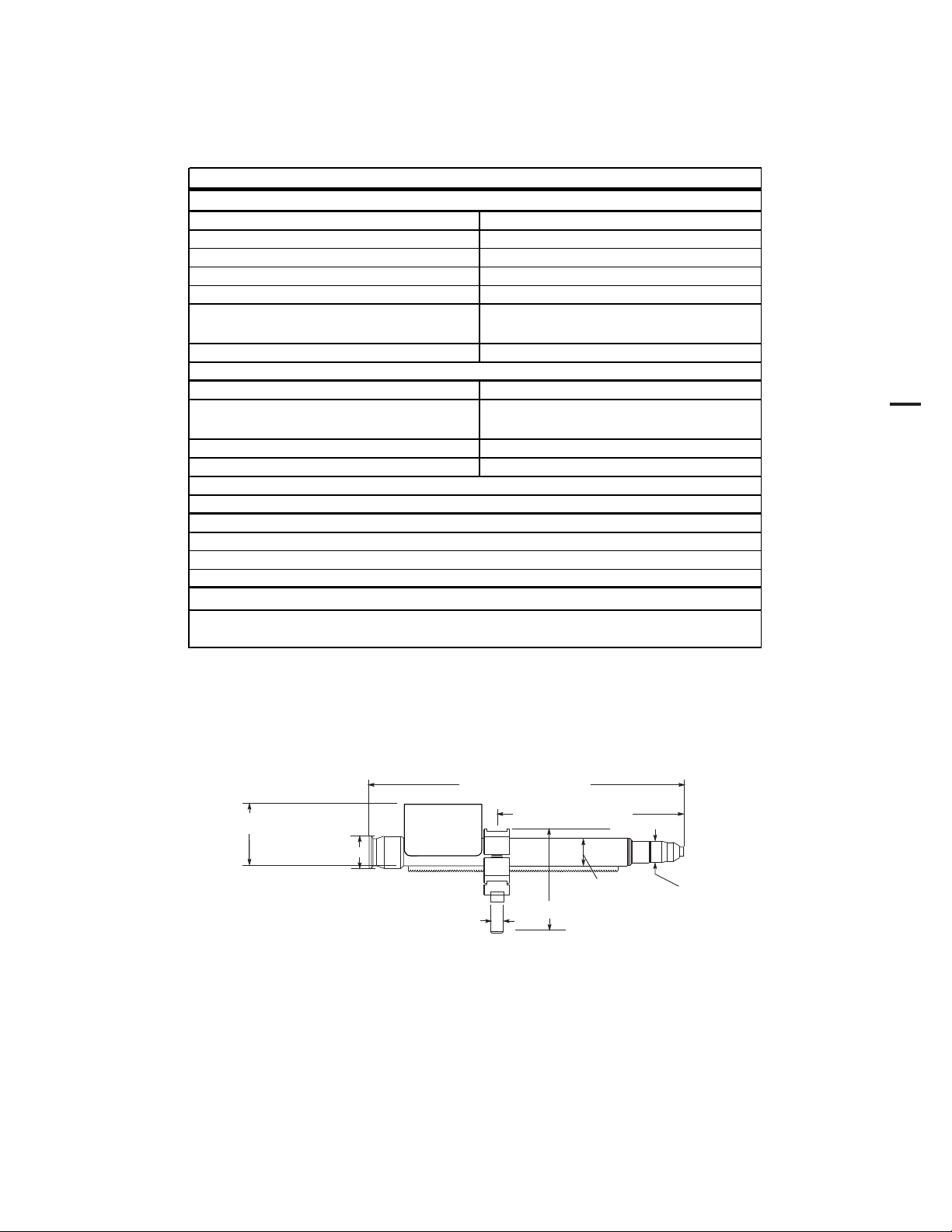
A. Torch Configuration
The standard machine torch has a positioning tube with rack & pinch block assembly.
2.875” / 73 mm
1.75" / 44.5 mm
15.875" / 403 mm
0.625" /
16 mm
9.285" / 236 mm
1.375" / 35 mm
4.95" / 126 mm
1.175" / 30 mm
Art # A-07402
Manual 0-4642 2-5 INTRODUCTION
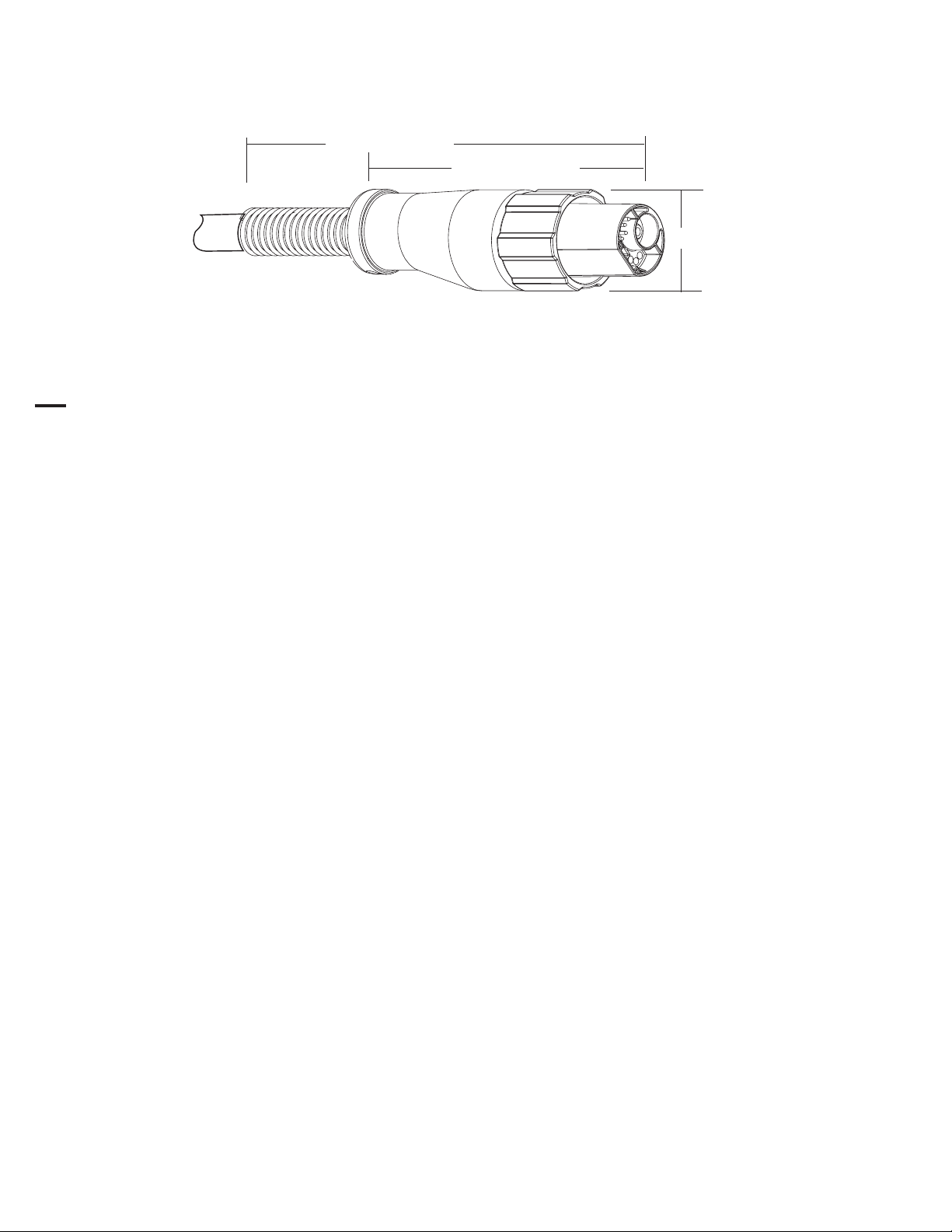
B. Torch Connector Dimensions
Art # A-04056
C. Torch Parts
Start Cartridge, Electrode, Tip, Shield Cup Body, Shield Cap
D. Parts - In - Place (PIP)
2
Torch Head has built - in switch
12 vdc circuit rating
E. Direct Contact Hazard
For exposed tip the recommended standoff is 3/16 inches / 4.7 mm.
8.5" / 216 mm
5.375" / 137 mm
1.9" / 50 mm
2.07 Torch Options and Accessories
These items can adapt a standard system to a particular application or further enhance performance (refer to Section 6
for ordering information).
• Spare Parts Kits - Various kits containing replacement consumable torch parts.
• Pinion Assembly (for machine torches)
• Leather Leads Covers
INTRODUCTION 2-6 Manual 0-4642
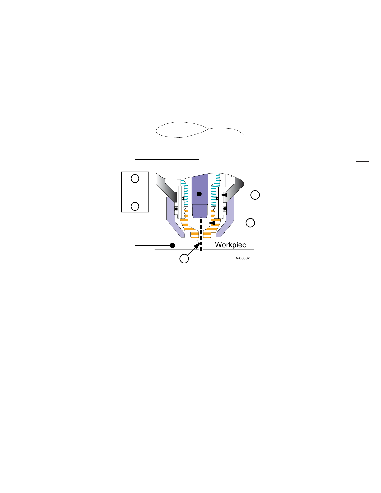
2.08 Introduction to Plasma
A. Plasma Gas Flow
Plasma is a gas which has been heated to an extremely high temperature and ionized so that it becomes electrically
conductive. The plasma arc cutting and gouging processes use this plasma to transfer an electrical arc to the workpiece. The
metal to be cut or removed is melted by the heat of the arc and then blown away.
In a Plasma Cutting Torch a cool gas enters Zone B, where a pilot arc between the electrode and the torch tip heats and
ionizes the gas. The main cutting arc then transfers to the workpiece through the column of plasma gas in Zone C.
_
Power
Supply
+
A
2
B
Workpiece
C
Typical Torch Head Detail
By forcing the plasma gas and electric arc through a small orifice, the torch delivers a high concentration of heat to a small
area. The stiff, constricted plasma arc is shown in Zone C. Direct current (DC) straight polarity is used for plasma cutting, as
shown in the illustration.
Zone A channels a secondary gas that cools the torch. This gas also assists the high velocity plasma gas in blowing
the molten metal out of the cut allowing for a fast, slag - free cut.
B. Gas Distribution
The single gas used is internally split into plasma and secondary gases.
The plasma gas flows into the torch through the negative lead, through the start cartridge, around the electrode,
and out through the tip orifice.
The secondary gas flows down around the outside of the torch start cartridge, and out between the tip and shield
cup around the plasma arc.
A-00002
C. Pilot Arc
When the torch is started a pilot arc is established between the electrode and cutting tip. This pilot arc creates a
path for the main arc to transfer to the work.
Manual 0-4642 2-7 INTRODUCTION

D. Main Cutting Arc
DC power is also used for the main cutting arc. The negative output is connected to the torch electrode through the
torch lead. The positive output is connected to the workpiece via the work cable and to the torch through a pilot
wire.
E. Parts - In - Place (PIP)
The torch leads include a ‘Parts - In - Place’ (PIP) circuit. When the torch shield cup is properly installed, it closes
a switch. The torch will not operate if this switch is open.
2
To Control
Cable Wiring
PIP Switch
Parts - In - Place Circuit Diagram
Shield Cup
A-03504
INTRODUCTION 2-8 Manual 0-4642

SECTION 3: INSTALLATION
3.01 Unpacking
1. Use the packing lists to identify and account for each item.
2. Inspect each item for possible shipping damage. If damage is evident, contact your distributor and / or shipping
company before proceeding with the installation.
3. Record Power Supply and Torch model and serial numbers, purchase date and vendor name, in the information
block at the front of this manual.
3.02 Lifting Options
The Power Supply includes a handle for hand lifting only. Be sure unit is lifted and transported safely and securely.
WARNINGS
Do not touch live electrical parts.
Disconnect input power cord before moving unit.
FALLING EQUIPMENT can cause serious personal injury and can damage equipment.
HANDLE is not for mechanical lifting.
3
• Only persons of adequate physical strength should lift the unit.
• Lift unit by the handle, using two hands. Do not use straps for lifting.
• Use optional wheel kit, cart or similar device of adequate capacity to move unit.
• Place unit on a proper skid and secure in place before transporting with a fork lift or other vehicle.
Manual 0-4642 3-1 INSTALLATION

3.03 Primary Input Power Connections
CAUTION
Check your power source for correct voltage before plugging in or connecting the unit. The primary power
source, fuse, and any extension cords used must conform to local electrical code and the recommended circuit
protection and wiring requirements as specified in Section 2.03.
A. Connections to 208 / 230-Volt Power
The 208 / 230-Volt power supply includes a factory-installed input power cable and plug.
1. Check your power source for correct voltage before plugging in the unit.
2. Connect the input power cable (or close the main disconnect switch) to supply power to the system.
CAUTION
The primary power source and power cable must conform to local electrical code and the recommended circuit
protection and wiring requirements (refer to table in Section 2.03).
B. Connections to 400-Volt, 415-Volt, 460-Volt, or 600-Volt Three-Phase Power
3
These Power Supplies are equipped with a four-conductor input power cable for three-phase input power. The 460-Volt Power
Supply will accept 460-VAC, Single-Phase input power with a change of input power cable.
1. Check your power source for correct voltage before plugging in the unit.
2. The input cable's outer covering is stripped back at the factory to expose the individual wires at the free end of the cable.
3. Connect the ends of the individual wires to a customer supplied plug or main disconnect as follows:
CAUTION
The primary power source and power cable must conform to local electrical code and the recommended circuit
protection and wiring requirements (refer to table in Section 2 ). All the input cable wires must be connected for
three-phase operation.
• Green / Yellow wire to Ground.
• Remaining wires to L1, L2, L3 input.
4. Connect the input power cable (or close the main disconnect switch) to supply power to the system.
INSTALLATION 3-2 Manual 0-4642
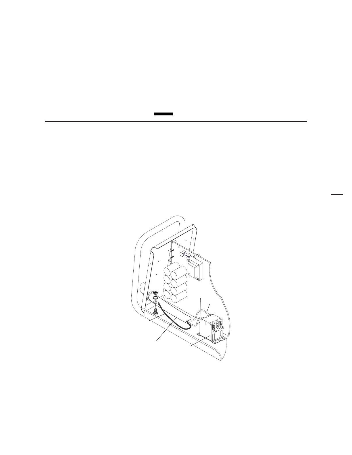
C. Connections to 460-Volt Single - Phase Power
The 460-Volt Power Supply will accept 460-VAC, Single-Phase input power with a change of input power cable.
1. Remove the Power Supply cover per section 5.09-A.
2. Disconnect the original input power cable from the main input contactor and the chassis ground connection.
3. Loosen the through-hole protector on the back panel of the power supply. Pull the original power cable out of the power
supply.
4. Pass a customer-supplied, three-conductor input power cable through the access opening in the back panel of the power
supply. Refer to Section 2 for power cable specifications.
CAUTION
The primary power source and power cable must conform to local electrical code and the recommended circuit
protection and wiring requirements (refer to table in Section 2.03).
5. Strip back the insulation on the individual wires.
6. Connect to main input contactor as follows:
• Line 1 wire to terminal L1.
• Line 3 wire to terminal L3.
7. Connect the ground wire to Ground (Earth). The Ground wire connection requires a ring terminal.
8. Tighten the through-hole protector to secure the power cable.
3
L1
L3
L1 L2 L3
Ground Wire
with Ring
Terminal
Input Cable
A-03041
Main Input
Contactor
Input Power Connections, 460 VAC, Single-Phase
9. Replace the Power Supply cover.
10. Connect the input power cable (or close the main disconnect switch) to supply power to the system.
Manual 0-4642 3-3 INSTALLATION
3
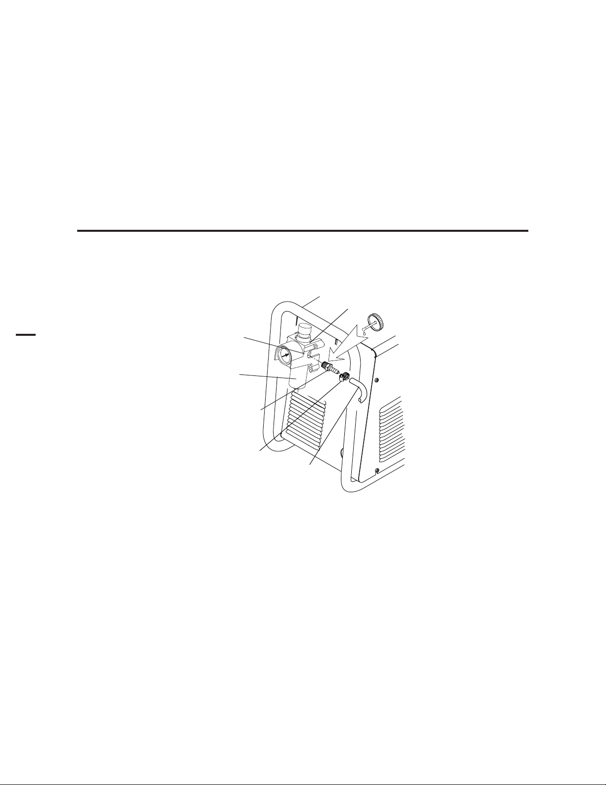
3.04 Gas Connections
A. Connecting Gas Supply to Unit
Use only compressed air with this power supply.
An in-line pneumatic dryer & evaporator type air filter, capable of filtering to at least 5 microns, is required when using air from a
compressor. This type filter will insure that moisture, oil, dirt, chips, rust particles, and other contaminants from the supply hose
do not enter the torch. For highly automated applications, a refrigerated drier may be used.
The connection is the same for compressed air from a compressor from high pressure cylinders. Refer to subsection 3.4-B or 3.4C if an additional air line filter is to be installed.
1. Connect the air line to the inlet port. The illustration shows typical fittings as an example. Other fittings can be
used.
NOTE
For a secure seal, apply thread sealant to the fitting threads, according to manufacturer's instructions. Do not use
Teflon tape as a thread sealer, as small particles of the tape may break off and block the small air passages in the torch.
Regulator/Filter
Assembly
Inlet Port
Bowl
1/4 NPT to 1/4"
(6mm) Fitting
Hose Clamp
Art # A-02999
Air Connection to Inlet Port
Gas Supply
Hose
INSTALLATION 3-4 Manual 0-4642
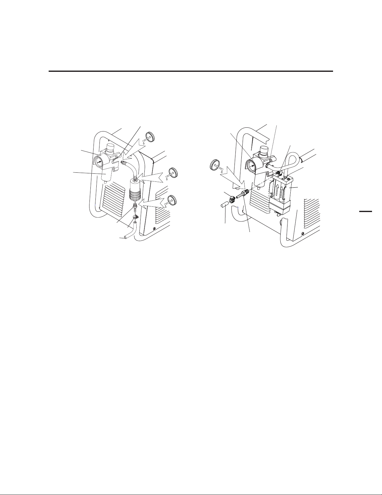
B. Optional Air Filters
t
1. Connect the Filter as illustrated. Use only Synflex or equivalent grade hose. The illustrations show typical fittings as an
example.
NOTE
For a secure seal, apply thread sealant to the fitting threads, according to the maker's instructions. Do Not use
Teflon tape as a thread sealer, as small particles of the tape may break off and block the small air passages in the
torch. Connect as follows:
Regulator Inlet Port
2-Stage Filter
Inlet Port (IN)
Regulator/Filter
Assembly
Bowl
Inlet Port
Regulator/Filter
Assembly
Hose
Clamp
1/4 NPT Hose Fitting
Hose Clamp
1/4" (6 mm) Gas Supply Hose
Art # A-03000
1/4" (6 mm) Gas
Supply Hose)
1/4 NPT
Hose Fitting
Optional Single-Stage Filter Installation Optional Two-Stage Filter Installation
Outlet Por
(OUT)
Two Stage
Filter
Assembly
3
Art # A-03004
Manual 0-4642 3-5 INSTALLATION

3
D. Using High Pressure Air Cylinders
When using high pressure air cylinders as the air supply:
1. Refer to the manufacturer’s specifications for installation and maintenance procedures for high pressure regulators.
2. Examine the cylinder valves to be sure they are clean and free of oil, grease or any foreign material. Briefly open
each cylinder valve to blow out any dust which may be present.
3. The cylinder must be equipped with an adjustable high-pressure regulator capable of outlet pressures up to 100 psi (6.9 bar)
maximum and flows of at least 500 scfh (236 lpm).
4. Connect supply hose to the cylinder.
NOTE
Pressure should be set at 100 psi (6.9 bar) at the high pressure cylinder regulator.
Supply hose must be at least 1/4 inch (6 mm) I.D.
For a secure seal, apply thread sealant to the fitting threads, according to manufacturer's instructions. Do Not use
Teflon tape as a thread sealer, as small particles of the tape may break off and block the small air passages in the torch.
INSTALLATION 3-6 Manual 0-4642
Loading...