


HMC-410
AUTOMATIC &
SEMI-AUTOMATIC
CONTROL PANEL
Art # A-04355
Instruction Manual
Version No: AA.02 |
Issue Date: July 27, 2005 |
Manual #: 430429-445 |
Operating Features:
 120 50Hz 888
VAC 60 IPM

WE APPRECIATE YOUR BUSINESS!
Congratulations on your new Thermal Arc product. We are proud to have you as our customer and will strive to provide you with the best service and reliability in the industry. This product is backed by our extensive warranty and world-wide service network. To locate your nearest distributor or service agency call 1-800-752-7621, or visit us on the web at www.Thermalarc.com.
This Operating Manual has been designed to instruct you on the correct use and operation of your Thermal Arc product. Your satisfaction with this product and its safe operation is our ultimate concern. Therefore please take the time to read the entire manual, especially the Safety Precautions. They will help you to avoid potential hazards that may exist when working with this product.
YOU ARE IN GOOD COMPANY!
The Brand of Choice for Contractors and Fabricators Worldwide.
Thermal Arc is a Global Brand of Arc Welding Products for Thermadyne Industries Inc. We manufacture and supply to major welding industry sectors worldwide including; Manufacturing, Construction, Mining, Automotive, Aerospace, Engineering, Rural and DIY/Hobbyist.
We distinguish ourselves from our competition through marketleading, dependable products that have stood the test of time. We pride ourselves on technical innovation, competitive prices, excellent delivery, superior customer service and technical support, together with excellence in sales and marketing expertise.
Above all, we are committed to develop technologically advanced products to achieve a safer working environment within the welding industry.

WARNINGS
Read and understand this entire Manual and your employer’s safety practices before installing, operating, or servicing the equipment.
While the information contained in this Manual represents the Manufacturer's best judgement, the Manufacturer assumes no liability for its use.
HMC-410 Automatic/Semi-Automatic Control Panel
Instruction Manual Number 430429-445 for:
Spec Number 100050-1
Spec Number 100050-2
Published by: Thermadyne Industries 82 Benning Street
West Lebanon, New Hampshire, USA 03784 (603) 298-5711
www.thermalarc.com
Copyright 2005 by
Thermal Dynamics Corporation
All rights reserved.
Reproduction of this work, in whole or in part, without written permission of the publisher is prohibited.
The publisher does not assume and hereby disclaims any liability to any party for any loss or damage caused by any error or omission in this Manual, whether such error results from negligence, accident, or any other cause.
Publication Date: Juky 27, 2005
Record the following information for Warranty purposes:
Where Purchased: |
___________________________________ |
Purchase Date: |
___________________________________ |
Equipment Serial #: |
___________________________________ |
i
TABLE OF CONTENTS
SECTION 1: |
|
|
SAFETY INSTRUCTIONS AND WARNINGS ....................................................... |
1-1 |
|
1.01 |
Arc Welding Hazards ...................................................................................... |
1-1 |
1.02 |
PRINCIPAL SAFETY STANDARDS .................................................................. |
1-5 |
1.03 |
PRECAUTIONS DE SECURITE EN SOUDAGE A L’ARC .................................... |
1-6 |
1.04 |
Dangers relatifs au soudage à l’arc ................................................................. |
1-6 |
1.05 |
PRINCIPALES NORMES DE SECURITE ........................................................ |
1-10 |
1.06 |
DECLARATION OF CONFORMITY ................................................................. |
1-11 |
1.07 |
LIMITED WARRANTY ................................................................................... |
1-12 |
SECTION 2: |
|
|
INTRODUCTION ...................................................................................... |
2-1 |
|
2.01 |
How To Use This Manual ................................................................................ |
2-1 |
2.02 |
Equipment Identification................................................................................. |
2-1 |
2.03 |
Receipt Of Equipment ..................................................................................... |
2-1 |
2.04 |
Symbol Chart ................................................................................................. |
2-2 |
2.05 |
General Information ....................................................................................... |
2-3 |
2.06 |
Product Specifications ................................................................................... |
2-3 |
2.07 |
Front Panel Controls ....................................................................................... |
2-7 |
2.08 |
Rear Panel Connections ............................................................................... |
2-11 |
2.09 |
Power Source Interface Description ............................................................. |
2-13 |
2.10 |
Hardware Description ................................................................................... |
2-14 |
SECTION 3: |
|
|
INSTALLATION ....................................................................................... |
3-1 |
|
3.01 |
Location ......................................................................................................... |
3-1 |
3.02 |
Assembly ........................................................................................................ |
3-1 |
3.03 |
Electrical Connections .................................................................................... |
3-1 |
3.04 |
Load Suppression .......................................................................................... |
3-1 |
3.05 |
Grounding ...................................................................................................... |
3-2 |
SECTION 4: |
|
|
OPERATION........................................................................................... |
|
4-1 |
4.01 |
System Configuration ..................................................................................... |
4-1 |
4.02 |
Softswitch Description (Table 4-1) ................................................................. |
4-2 |
4.03 |
System Setup ............................................................................................... |
4-10 |
4.04 |
HMC-410 Setup Checklist ............................................................................ |
4-12 |
4.05 |
Programming ............................................................................................... |
4-13 |
4.06 |
Setup ............................................................................................................ |
4-16 |
4.07 |
Operation ...................................................................................................... |
4-17 |
TABLETABLEOF CONTENTSOF CONTENTS(continued)
SECTION 5: |
|
|
SERVICE .............................................................................................. |
|
5-1 |
5.01 |
Maintenance ................................................................................................... |
5-1 |
5.02 |
Controller Maintenance .................................................................................. |
5-1 |
5.03 |
Troubleshooting ............................................................................................. |
5-1 |
5.04 |
Troubleshooting Guide ................................................................................... |
5-2 |
5.05 |
Diagnostics..................................................................................................... |
5-6 |
5.06 |
Built In Test (BIT) Definition ........................................................................... |
5-7 |
5.06 |
Built In Test (BIT) Definition (continued as Table 5-1b) .................................. |
5-8 |
5.06 |
Built In Test (BIT) Definition (continued as Table 5-1c) .................................. |
5-9 |
SECTION 6: |
|
|
ACCESSORIES AND OPTION DESCRIPTIONS.................................................... |
6-1 |
|
6.01 |
Remote Pendant Description .......................................................................... |
6-1 |
6.02 |
Feedhead ........................................................................................................ |
6-1 |
6.03 |
Feed Roll Kits ................................................................................................. |
6-1 |
6.04 |
Control Cables: ............................................................................................... |
6-2 |
6.05 |
171238-17 Software Kits ................................................................................ |
6-2 |
6.06 |
171238-19 Software Kits ................................................................................ |
6-3 |
6.07 |
171238 Software Kits ..................................................................................... |
6-3 |
6.08 |
870236 Robotic Interface Kits ........................................................................ |
6-4 |
6.09 |
870236-002 Fanuc Robotic Interface Kit ........................................................ |
6-5 |
6.10 |
870236-003 Comau Robotic Interface Kit ...................................................... |
6-6 |
6.11 |
Other Available Options .................................................................................. |
6-7 |
SECTION 7: |
|
|
GLOSSARY ........................................................................................... |
|
7-1 |
SECTION 8: |
|
|
PARTS LIST .......................................................................................... |
|
6-1 |
8.01 |
Equipment Identification ................................................................................. |
6-1 |
8.02 |
How To Use This Parts List ............................................................................ |
6-1 |
8.03 |
Parts List for the Control Box Assembly (1 of 2) ............................................ |
6-2 |
8.03 |
Parts List for the Control Box Assembly (2 of 2) ............................................ |
6-4 |
8.04 |
Parts List for the Remote Pendant ................................................................. |
6-6 |
APPENDIX 1: GENERAL INFORMATION ................................................................. |
A-1 |
|
APPENDIX 2: SCHEMATIC DIAGRAM 1 OF 4 ........................................................... |
A-2 |
|
APPENDIX 3: SCHEMATIC DIAGRAM 2 OF 4 ........................................................... |
A-4 |
|
APPENDIX 4: SCHEMATIC DIAGRAM 3 OF 4 ........................................................... |
A-6 |
|
APPENDIX 5: SCHEMATIC DIAGRAM 4 OF 4 ........................................................... |
A-8 |
|
TABLE OF CONTENTS
APPENDIX 6: SYSTEM OUTLINE 1 OF 2 ............................................................... |
A-10 |
APPENDIX 7: SYSTEM OUTLINE 2 OF 2 ............................................................... |
A-11 |
HMC-410
SECTION 1:
SAFETY INSTRUCTIONS AND WARNINGS
WARNING
PROTECT YOURSELF AND OTHERS FROM POSSIBLE SERIOUS INJURY OR DEATH. KEEP CHILDREN AWAY. PACEMAKER WEARERS KEEP AWAY UNTIL CONSULTING YOUR DOCTOR. DO NOT LOSE THESE INSTRUCTIONS. READ OPERATING/INSTRUCTION MANUAL BEFORE INSTALLING, OPERATING OR SERVICING THIS EQUIPMENT.
Welding products and welding processes can cause serious injury or death, or damage to other equipment or property, if the operator does not strictly observe all safety rules and take precautionary actions.
Safe practices have developed from past experience in the use of welding and cutting. These practices must be learned through study and training before using this equipment. Some of these practices apply to equipment
connected to power lines; other practices apply to engine driven equipment. Anyone not having extensive training in welding and cutting practices should not attempt to weld.
Safe practices are outlined in the American National Standard Z49.1 entitled: SAFETY IN WELDING AND CUTTING. This publication and other guides to what you should learn before operating this equipment are listed at the end of these safety precautions. HAVE ALL INSTALLATION, OPERATION, MAINTENANCE, AND REPAIR WORK PERFORMED
ONLY BY QUALIFIED PEOPLE.
1.01 Arc Welding Hazards
WARNING
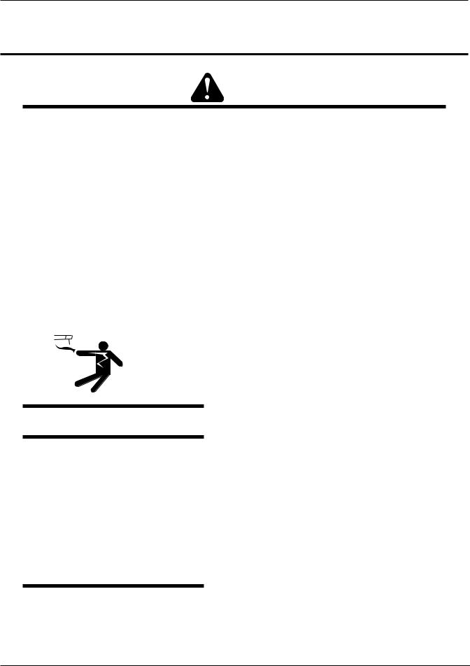
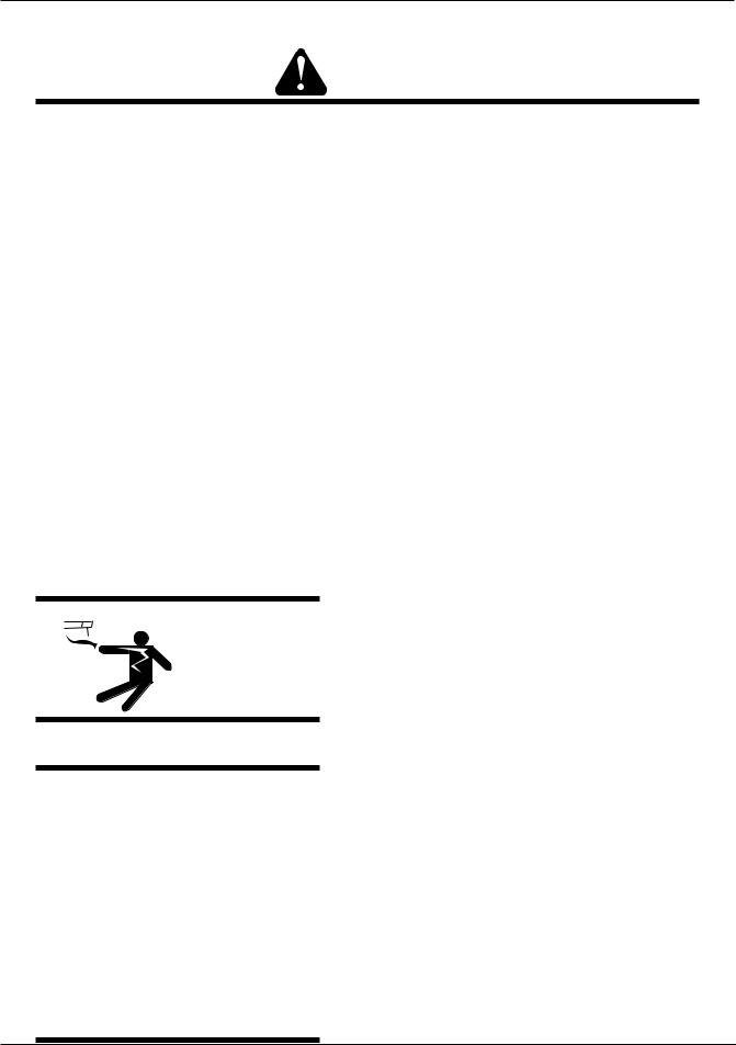
ELECTRIC SHOCK can kill.
Touching live electrical parts can cause fatal shocks or severe burns. The electrode and work circuit is electrically live whenever the output is on. The input power circuit and machine internal circuits are also live when power is on. In semiautomatic or automatic wire welding, the wire, wire reel, drive roll housing, and all metal parts touching the welding wire are electrically live. Incorrectly installed or improperly grounded equipment is a hazard.
1.Do not touch live electrical parts.
2.Wear dry, hole-free insulating gloves and body protection.
3.Insulate yourself from work and ground using dry insulating mats or covers.
4.Disconnect input power or stop engine before installing or servicing this equipment. Lock input power disconnect switch open, or remove line fuses so power cannot be turned on accidentally.
5.Properly install and ground this equipment according to its Owner’s Manual and national, state, and local codes.
6.Turn off all equipment when not in use. Disconnect power to equipment if it will be left unattended or out of service.
7.Use fully insulated electrode holders. Never dip holder in water to cool it or lay it down on the ground or the work surface. Do not touch holders connected to two welding machines at the same time or touch other people with the holder or electrode.
8.Do not use worn, damaged, undersized, or poorly spliced cables.
9.Do not wrap cables around your body.
10.Ground the workpiece to a good electrical (earth) ground.
July 27, 2005 |
1-1 |

HMC-410
11.Do not touch electrode while in contact with the work (ground) circuit.
12.Use only well-maintained equipment. Repair or replace damaged parts at once.
13.In confined spaces or damp locations, do not use a welder with AC output unless it is equipped with a voltage reducer. Use equipment with DC output.
14.Wear a safety harness to prevent falling if working above floor level.
15.Keep all panels and covers securely in place.
WARNING
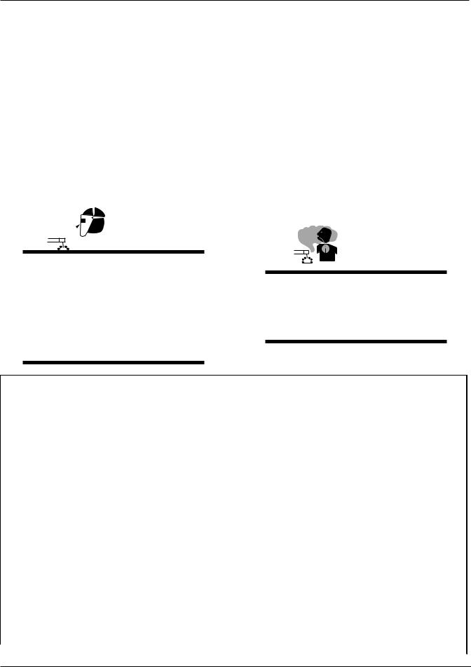
ARC RAYS can burn eyes and skin; NOISE can damage hearing.
Arc rays from the welding process produce intense heat and strong ultraviolet rays that can burn eyes and skin. Noise from some processes can damage hearing.
1.Wear a welding helmet fitted with a proper shade of filter (see ANSI Z49.1 listed in Safety Standards) to protect your face and eyes when welding or watching.
2.Wear approved safety glasses. Side shields recommended.
3.Use protective screens or barriers to protect others from flash and glare; warn others not to watch the arc.
4.Wear protective clothing made from durable, flameresistant material (wool and leather) and foot protection.
5.Use approved ear plugs or ear muffs if noise level is high.
WARNING
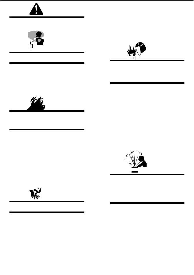
FUMES AND GASES can be hazardous to your health.
Welding produces fumes and gases. Breathing these fumes and gases can be hazardous to your health.
1.Keep your head out of the fumes. Do not breath the fumes.
2.If inside, ventilate the area and/or use exhaust at the arc to remove welding fumes and gases.
3.If ventilation is poor, use an approved air-supplied respirator.
4.Read the Material Safety Data Sheets (MSDSs) and the manufacturer’s instruction for metals, consumables, coatings, and cleaners.
5.Work in a confined space only if it is well ventilated, or while wearing an air-supplied respirator. Shielding gases used for welding can displace air causing injury or death. Be sure the breathing air is safe.
Eye protection filter shade selector for welding or cutting (goggles or helmet), from AWS A6.2-73.
Welding or cutting |
Electrode Size |
Filter |
Welding or cutting |
Electrode Size |
Filter |
Torch soldering |
|
2 |
Gas metal-arc |
|
|
Torch brazing |
|
3 or 4 |
Non-ferrous base metal |
All |
11 |
Oxygen Cutting |
|
|
Ferrous base metal |
All |
12 |
Light |
Under 1 in., 25 mm |
3 or 4 |
Gas tungsten arc welding |
All |
12 |
Medium |
1 to 6 in., 25-150 mm |
4 or 5 |
(TIG) |
All |
12 |
Heavy |
Over 6 in., 150 mm |
5 or 6 |
Atomic hydrogen welding |
All |
12 |
Gas welding |
|
|
Carbon arc welding |
All |
12 |
Light |
Under 1/8 in., 3 mm |
4 or 5 |
Plasma arc welding |
|
|
Medium |
1/8 to 1/2 in., 3-12 mm |
5 or 6 |
Carbon arc air gouging |
|
|
Heavy |
Over 1/2 in., 12 mm |
6 or 8 |
Light |
|
12 |
Shielded metal-arc |
Under 5/32 in., 4 mm |
10 |
Heavy |
|
14 |
|
5/32 to 1/4 in., |
12 |
Plasma arc cutting |
|
|
|
Over 1/4 in., 6.4 mm |
14 |
Light |
Under 300 Amp |
9 |
|
|
|
Medium |
300 to 400 Amp |
12 |
|
|
|
Heavy |
Over 400 Amp |
14 |
1-2 |
July 27, 2005 |

HMC-410
6.Do not weld in locations near degreasing, cleaning, or spraying operations. The heat and rays of the arc can react with vapors to form highly toxic and irritating gases.
7.Do not weld on coated metals, such as galvanized, lead, or cadmium plated steel, unless the coating is removed from the weld area, the area is well ventilated, and if necessary, while wearing an air-supplied respirator. The coatings and any metals containing these elements can give off toxic fumes if welded.
WARNING
WELDING can cause fire or explosion.
Sparks and spatter fly off from the welding arc. The flying sparks and hot metal, weld spatter, hot workpiece, and hot equipment can cause fires and burns. Accidental contact of electrode or welding wire to metal objects can cause sparks, overheating, or fire.
1.Protect yourself and others from flying sparks and hot metal.
2.Do not weld where flying sparks can strike flammable material.
3.Remove all flammables within 35 ft (10.7 m) of the welding arc. If this is not possible, tightly cover them with approved covers.
4.Be alert that welding sparks and hot materials from welding can easily go through small cracks and openings to adjacent areas.
5.Watch for fire, and keep a fire extinguisher nearby.
6.Be aware that welding on a ceiling, floor, bulkhead, or partition can cause fire on the hidden side.
7.Do not weld on closed containers such as tanks or drums.
8.Connect work cable to the work as close to the welding area as practical to prevent welding current from traveling long, possibly unknown paths and causing electric shock and fire hazards.
9.Do not use welder to thaw frozen pipes.
10.Remove stick electrode from holder or cut off welding wire at contact tip when not in use.
WARNING
FLYING SPARKS AND HOT METAL can cause injury.
Chipping and grinding cause flying metal. As welds cool, they can throw off slag.
1.Wear approved face shield or safety goggles. Side shields recommended.
2.Wear proper body protection to protect skin.
WARNING
CYLINDERS can explode if damaged.
Shielding gas cylinders contain gas under high pressure. If damaged, a cylinder can explode. Since gas cylinders are normally part of the welding process, be sure to treat them carefully.
1.Protect compressed gas cylinders from excessive heat, mechanical shocks, and arcs.
2.Install and secure cylinders in an upright position by chaining them to a stationary support or equipment cylinder rack to prevent falling or tipping.
3.Keep cylinders away from any welding or other electrical circuits.
4.Never allow a welding electrode to touch any cylinder.
5.Use only correct shielding gas cylinders, regulators, hoses, and fittings designed for the specific application; maintain them and associated parts in good condition.
6.Turn face away from valve outlet when opening cylinder valve.
7.Keep protective cap in place over valve except when cylinder is in use or connected for use.
8.Read and follow instructions on compressed gas cylinders, associated equipment, and CGA publication P-1 listed in Safety Standards.
July 27, 2005 |
1-3 |
HMC-410
WARNING
Engines can be dangerous.
WARNING
ENGINE EXHAUST GASES can kill.
Engines produce harmful exhaust gases.
1.Use equipment outside in open, well-ventilated areas.
2.If used in a closed area, vent engine exhaust outside and away from any building air intakes.
 WARNING
ENGINE FUEL can cause fire or explosion.
Engine fuel is highly flammable.
1.Stop engine before checking or adding fuel.
2.Do not add fuel while smoking or if unit is near any sparks or open flames.
3.Allow engine to cool before fueling. If possible, check and add fuel to cold engine before beginning job.
4.Do not overfill tank — allow room for fuel to expand.
5.Do not spill fuel. If fuel is spilled, clean up before starting engine.

 WARNING
MOVING PARTS can cause injury.
Moving parts, such as fans, rotors, and belts can cut fingers and hands and catch loose clothing.
1.Keep all doors, panels, covers, and guards closed and securely in place.
2.Stop engine before installing or connecting unit.
3.Have only qualified people remove guards or covers for maintenance and troubleshooting as necessary.
4.To prevent accidental starting during servicing, disconnect negative (-) battery cable from battery.
5.Keep hands, hair, loose clothing, and tools away from moving parts.
6.Reinstall panels or guards and close doors when servicing is finished and before starting engine.
WARNING
SPARKS can cause BATTERY GASES TO EXPLODE; BATTERY ACID can burn eyes and skin.
Batteries contain acid and generate explosive gases.
1.Always wear a face shield when working on a battery.
2.Stop engine before disconnecting or connecting battery cables.
3.Do not allow tools to cause sparks when working on a battery.
4.Do not use welder to charge batteries or jump start vehicles.
5.Observe correct polarity (+ and –) on batteries.
WARNING
STEAM AND PRESSURIZED HOT COOLANT can burn face, eyes, and skin.
The coolant in the radiator can be very hot and under pressure.
1.Do not remove radiator cap when engine is hot. Allow engine to cool.
2.Wear gloves and put a rag over cap area when removing cap.
3.Allow pressure to escape before completely removing cap.
1-4 |
July 27, 2005 |
HMC-410
WARNING
This product, when used for welding or cutting, produces fumes or gases which contain chemicals know to the State of California to cause birth defects and, in some cases, cancer. (California Health & Safety code Sec. 25249.5 et seq.)
NOTE
Considerations About Welding And The Effects of Low Frequency Electric and Magnetic Fields
The following is a quotation from the General Conclusions Section of the U.S. Congress, Office of Technology Assessment, Biological Effects of Power Frequency Electric & Magnetic Fields - Background Paper, OTA-BP-E-63 (Washington, DC: U.S. Government Printing Office, May 1989): “...there is now a very large volume of scientific findings based on experiments at the cellular level and from studies with animals and people which clearly establish that low frequency magnetic fields and interact with, and produce changes in, biological systems. While most of this work is of very high quality, the results are complex. Current scientific understanding does not yet allow us to interpret the evidence in a single coherent framework. Even more frustrating, it does not yet allow us to draw definite conclusions about questions of possible risk or to offer clear science-based advice on strategies to minimize or avoid potential risks.”
To reduce magnetic fields in the workplace, use the following procedures.
1.Keep cables close together by twisting or taping them.
2.Arrange cables to one side and away from the operator.
3.Do not coil or drape cable around the body.
4.Keep welding power source and cables as far away from body as practical.
ABOUT PACEMAKERS:
The above procedures are among those also normally recommended for pacemaker wearers. Consult your doctor for complete information.
1.02 PRINCIPAL SAFETY STANDARDS
Safety in Welding and Cutting, ANSI Standard Z49.1, from American Welding Society, 550 N.W. LeJeune Rd., Miami, FL 33126.
Safety and Health Standards, OSHA 29 CFR 1910, from Superintendent of Documents, U.S. Government Printing Office, Washington, D.C. 20402.
Recommended Safe Practices for the Preparation for Welding and Cutting of Containers That Have Held Hazardous Substances, American Welding Society Standard AWS F4.1, from American Welding Society, 550 N.W. LeJeune Rd., Miami, FL 33126.
National Electrical Code, NFPA Standard 70, from National Fire Protection Association, Batterymarch Park, Quincy, MA 02269.
Safe Handling of Compressed Gases in Cylinders, CGA Pamphlet P-1, from Compressed Gas Association, 1235 Jefferson Davis Highway, Suite 501, Arlington, VA 22202.
Code for Safety in Welding and Cutting, CSA Standard W117.2, from Canadian Standards Association, Standards Sales, 178 Rexdale Boulevard, Rexdale, Ontario, Canada M9W 1R3.
Safe Practices for Occupation and Educational Eye and Face Protection, ANSI Standard Z87.1, from American National Standards Institute, 1430 Broadway, New York, NY 10018.
Cutting and Welding Processes, NFPA Standard 51B, from National Fire Protection Association, Batterymarch Park, Quincy, MA 02269.
July 27, 2005 |
1-5 |
HMC-410
1.03 PRECAUTIONS DE SECURITE EN SOUDAGE A L’ARC
MISE EN GARDE
LE SOUDAGE A L’ARC EST DANGEREUX
PROTEGEZ-VOUS, AINSI QUE LES AUTRES, CONTRE LES BLESSURES GRAVES POSSIBLES OU LA MORT. NE LAISSEZ PAS LES ENFANTS S’APPROCHER, NI LES PORTEURS DE STIMULATEUR CARDIAQUE (A MOINS QU’ILS N’AIENT CONSULTE UN MEDECIN). CONSERVEZ CES INSTRUCTIONS. LISEZ LE MANUEL D’OPERATION OU LES INSTRUCTIONS AVANT D’INSTALLER, UTILISER OU ENTRETENIR CET EQUIPEMENT.
Les produits et procédés de soudage peuvent sauser des blessures graves ou la mort, de même que des dommages au reste du matériel et à la propriété, si l’utilisateur n’adhère pas strictement à toutes les règles de sécurité et ne prend pas les précautions nécessaires.
En soudage et coupage, des pratiques sécuritaires se sont développées suite à l’expérience passée. Ces pratiques doivent être apprises par étude ou entraînement avant d’utiliser l’equipement. Toute personne n’ayant pas suivi un entraînement intensif en soudage et coupage ne devrait pas tenter de souder. Certaines pratiques concernent les équipements raccordés aux lignes d’alimentation alors que d’autres s’adressent aux groupes électrogènes.
La norme Z49.1 de l’American National Standard, intitulée “SAFETY IN WELDING AND CUTTING” présente les pratiques sécuritaires à suivre. Ce document ainsi que d’autres guides que vous devriez connaître avant d’utiliser cet
équipement sont présentés à la fin de ces instructions de sécurité.
1. Ne touchez pas à des pièces sous tension.
2. Portez des gants et des vêtements isolants, secs et non troués.
3 Isolez-vous de la pièce à souder et de la mise à la terre au moyen de tapis isolants ou autres.
4. Déconnectez la prise d’alimentation de l’équipement ou arrêtez le moteur avant de l’installer ou d’en faire l’entretien. Bloquez le commutateur en circuit ouvert ou enlevez les fusibles de l’alimentation afin d’éviter une mise en marche accidentelle.
5. Veuillez à installer cet équipement et à le mettre à la terre selon le manuel d’utilisation et les codes nationaux, provinciaux et locaux applicables.
6. Arrêtez tout équipement après usage. Coupez l’alimentation de l’équipement s’il est hors d’usage ou inutilisé.
7. N’utilisez que des porte-électrodes bien isolés. Ne jamais plonger les porte-électrodes dans l’eau pour les refroidir. Ne jamais les laisser traîner par terre ou sur les pièces à souder. Ne touchez pas aux porteélectrodes raccordés à deux sources de courant en même temps. Ne jamais toucher quelqu’un d’autre avec l’électrode ou le porte-électrode.
8. N’utilisez pas de câbles électriques usés, endommagés, mal épissés ou de section trop petite.
9. N’enroulez pas de câbles électriques autour de votre corps.
1-6 |
July 27, 2005 |
HMC-410
10.N’utilisez qu’une bonne prise de masse pour la mise à la terre de la pièce à souder.
11.Ne touchez pas à l’électrode lorsqu’en contact avec le circuit de soudage (terre).
12.N’utilisez que des équipements en bon état. Réparez ou remplacez aussitôt les pièces endommagées.
13.Dans des espaces confinés ou mouillés, n’utilisez pas de source de courant alternatif, à moins qu’il soit muni d’un réducteur de tension. Utilisez plutôt une source de courant continu.
14.Portez un harnais de sécurité si vous travaillez en hauteur.
15.Fermez solidement tous les panneaux et les capots.

 AVERTISSEMENT
LE RAYONNEMENT DE L’ARC PEUT BRÛLER LES YEUX ET LA PEAU; LE BRUIT PEUT ENDOMMAGER L’OUIE.
L’arc de soudage produit une chaleur et des rayons ultraviolets intenses, susceptibles de brûler les yeux et la peau. Le bruit causé par certains procédés peut endommager l’ouïe.
1.Portez une casque de soudeur avec filtre oculaire de nuance appropriée (consultez la norme ANSI Z49 indiquée ci-après) pour vous protéger le visage et les yeux lorsque vous soudez ou que vous observez l’exécution d’une soudure.
2.Portez des lunettes de sécurité approuvées. Des écrans latéraux sont recommandés.
3.Entourez l’aire de soudage de rideaux ou de cloisons pour protéger les autres des coups d’arc ou de l’éblouissement; avertissez les observateurs de ne pas regarder l’arc.
4.Portez des vêtements en matériaux ignifuges et durables (laine et cuir) et des chaussures de sécurité.
5.Portez un casque antibruit ou des bouchons d’oreille approuvés lorsque le niveau de bruit est élevé.
AVERTISSEMENT
LES VAPEURS ET LES FUMEES SONT DANGEREUSES POUR LA SANTE.
Le soudage dégage des vapeurs et des fumées dangereuses à respirer.
SELECTION DES NUANCES DE FILTRES OCULAIRS POUR LA PROTECTION
DES YEUX EN COUPAGE ET SOUDAGE (selon AWS á 8.2-73)
Opération de coupage |
Dimension d'électrode ou |
Nuance de |
Opération de coupage |
Dimension d'électrode ou |
Nuance de |
|
ou soudage |
Epiasseur de métal ou |
filtre oculaire |
ou soudage |
Epiasseur de métal ou |
filtre oculaire |
|
Intensité de courant |
Intensité de courant |
|||||
|
|
|
|
|||
|
|
|
|
|
|
|
Brassage tendre |
toutes conditions |
2 |
Soudage á l'arc sous gaz |
|
|
|
au chalumeau |
avec fil plein (GMAW) |
|
|
|||
|
|
|
|
|||
Brassage fort |
toutes conditions |
3 ou 4 |
métaux non-ferreux |
toutes conditions |
11 |
|
au chalumeau |
||||||
|
|
|
|
|
||
Oxycoupage |
|
|
métaux ferreux |
toutes conditions |
12 |
|
|
|
|
|
|
|
|
mince |
moins de 1 po. (25 mm) |
2 ou 3 |
Soudage á l'arc sous gaz avec |
toutes conditions |
12 |
|
électrode de tungstène (GTAW) |
||||||
|
|
|
|
|
||
|
|
|
|
|
|
|
moyen |
de 1 á 6 po. (25 á 150 mm) |
4 ou 5 |
Soudage á l'hydrogène |
toutes conditions |
12 |
|
atomique (AHW) |
||||||
|
|
|
|
|
||
épais |
plus de 6 po. (150 mm) |
5 ou 6 |
Soudage á l'arc avec |
toutes conditions |
12 |
|
électrode de carbone (CAW) |
||||||
|
|
|
|
|
||
Soudage aux gaz |
|
|
Soudage á l'arc Plasma (PAW) |
toutes dimensions |
12 |
|
|
|
|
|
|
|
|
mince |
moins de 1/8 po. (3 mm) |
4 ou 5 |
Gougeage Air-Arc avec |
|
|
|
électrode de carbone |
|
|
||||
|
|
|
|
|
||
moyen |
de 1/8 á 1/2 po. (3 á 12 mm) |
5 ou 6 |
mince |
|
12 |
|
épais |
plus de 1/2 po. (12 mm) |
6 ou 8 |
épais |
|
14 |
|
|
|
|
|
|
|
|
Soudage á l'arc avec |
|
|
|
|
|
|
électrode enrobees |
moins de 5/32 po. (4 mm) |
10 |
Coupage á l'arc Plasma (PAC) |
|
|
|
(SMAW) |
|
|
|
|
|
|
|
5/32 á 1/4 po. (4 á 6.4 mm) |
12 |
mince |
moins de 300 amperès |
9 |
|
|
|
|
|
|
|
|
|
plus de 1/4 po. (6.4 mm) |
14 |
moyen |
de 300 á 400 amperès |
12 |
|
|
|
|
|
|
|
|
|
|
|
épais |
plus de 400 amperès |
14 |
July 27, 2005 |
1-7 |
HMC-410
1.Eloignez la tête des fumées pour éviter de les respirer.
2.A l’intérieur, assurez-vous que l’aire de soudage est bien ventilée ou que les fumées et les vapeurs sont aspirées à l’arc.
3.Si la ventilation est inadequate, portez un respirateur à adduction d’air approuvé.
4.Lisez les fiches signalétiques et les consignes du fabricant relatives aux métaux, aux produits consummables, aux revêtements et aux produits nettoyants.
5.Ne travaillez dans un espace confiné que s’il est bien ventilé; sinon, portez un respirateur à adduction d’air. Les gaz protecteurs de soudage peuvent déplacer l’oxygène de l’air et ainsi causer des malaises ou la mort. Assurez-vous que l’air est propre à la respiration.
6.Ne soudez pas à proximité d’opérations de dégraissage, de nettoyage ou de pulvérisation. La chaleur et les rayons de l’arc peuvent réagir avec des vapeurs et former des gaz hautement toxiques et irritants.
7.Ne soudez des tôles galvanisées ou plaquées au plomb ou au cadmium que si les zones à souder ont été grattées à fond, que si l’espace est bien ventilé; si nécessaire portez un respirateur à adduction d’air. Car ces revêtements et tout métal qui contient ces éléments peuvent dégager des fumées toxiques au moment du soudage.
AVERTISSEMENT
LE SOUDAGE PEUT CAUSER UN INCENDIE OU UNE EXPLOSION
L’arc produit des étincellies et des projections. Les particules volantes, le métal chaud, les projections de soudure et l’équipement surchauffé peuvent causer un incendie et des brûlures. Le contact accidentel de l’électrode ou du fil-électrode avec un objet métallique peut provoquer des étincelles, un échauffement ou un incendie.
1.Protégez-vous, ainsi que les autres, contre les étincelles et du métal chaud.
2.Ne soudez pas dans un endroit où des particules volantes ou des projections peuvent atteindre des matériaux inflammables.
3.Enlevez toutes matières inflammables dans un rayon de 10, 7 mètres autour de l’arc, ou couvrez-les soigneusement avec des bâches approuvées.
4.Méfiez-vous des projections brulantes de soudage susceptibles de pénétrer dans des aires adjacentes par de petites ouvertures ou fissures.
5.Méfiez-vous des incendies et gardez un extincteur à portée de la main.
6.N’oubliez pas qu’une soudure réalisée sur un plafond, un plancher, une cloison ou une paroi peut enflammer l’autre côté.
7.Ne soudez pas un récipient fermé, tel un réservoir ou un baril.
8.Connectez le câble de soudage le plus près possible de la zone de soudage pour empêcher le courant de suivre un long parcours inconnu, et prévenir ainsi les risques d’électrocution et d’incendie.
9.Ne dégelez pas les tuyaux avec un source de courant.
10.Otez l’électrode du porte-électrode ou coupez le fil au tube-contact lorsqu’inutilisé après le soudage.
11.Portez des vêtements protecteurs non huileux, tels des gants en cuir, une chemise épaisse, un pantalon revers, des bottines de sécurité et un casque.

 AVERTISSEMENT
LES ETINCELLES ET LES PROJECTIONS BRULANTES PEUVENT CAUSER DES BLESSURES.
Le piquage et le meulage produisent des particules métalliques volantes. En refroidissant, la soudure peut projeter du éclats de laitier.
1.Portez un écran facial ou des lunettes protectrices approuvées. Des écrans latéraux sont recommandés.
2.Portez des vêtements appropriés pour protéger la peau.
1-8 |
July 27, 2005 |
HMC-410
AVERTISSEMENT
LES BOUTEILLES ENDOMMAGEES PEUVENT EXPLOSER
Les bouteilles contiennent des gaz protecteurs sous haute pression. Des bouteilles endommagées peuvent exploser. Comme les bouteilles font normalement partie du procédé de soudage, traitez-les avec soin.
1.Protégez les bouteilles de gaz comprimé contre les sources de chaleur intense, les chocs et les arcs de soudage.
2.Enchainez verticalement les bouteilles à un support ou à un cadre fixe pour les empêcher de tomber ou d’être renversées.
3.Eloignez les bouteilles de tout circuit électrique ou de tout soudage.
4.Empêchez tout contact entre une bouteille et une électrode de soudage.
5.N’utilisez que des bouteilles de gaz protecteur, des détendeurs, des boyauxs et des raccords conçus pour chaque application spécifique; ces équipements et les pièces connexes doivent être maintenus en bon état.
6.Ne placez pas le visage face à l’ouverture du robinet de la bouteille lors de son ouverture.
7.Laissez en place le chapeau de bouteille sauf si en utilisation ou lorsque raccordé pour utilisation.
8.Lisez et respectez les consignes relatives aux bouteilles de gaz comprimé et aux équipements connexes, ainsi que la publication P-1 de la CGA, identifiée dans la liste de documents ci-dessous.
 AVERTISSEMENT
LES MOTEURS PEUVENT ETRE DANGEREUX
LES GAZ D’ECHAPPEMENT DES MOTEURS PEUVENT ETRE MORTELS.
Les moteurs produisent des gaz d’échappement nocifs.
1.Utilisez l’équipement à l’extérieur dans des aires ouvertes et bien ventilées.
2.Si vous utilisez ces équipements dans un endroit confiné, les fumées d’échappement doivent être envoyées à l’extérieur, loin des prises d’air du bâtiment.
 AVERTISSEMENT
LE CARBURANT PEUR CAUSER UN INCENDIE OU UNE EXPLOSION.
Le carburant est hautement inflammable.
1.Arrêtez le moteur avant de vérifier le niveau e carburant ou de faire le plein.
2.Ne faites pas le plein en fumant ou proche d’une source d’étincelles ou d’une flamme nue.
3.Si c’est possible, laissez le moteur refroidir avant de faire le plein de carburant ou d’en vérifier le niveau au début du soudage.
4.Ne faites pas le plein de carburant à ras bord: prévoyez de l’espace pour son expansion.
5.Faites attention de ne pas renverser de carburant. Nettoyez tout carburant renversé avant de faire démarrer le moteur.

 AVERTISSEMENT
DES PIECES EN MOUVEMENT PEUVENT CAUSER DES BLESSURES.
Des pièces en mouvement, tels des ventilateurs, des rotors et des courroies peuvent couper doigts et mains, ou accrocher des vêtements amples.
1.Assurez-vous que les portes, les panneaux, les capots et les protecteurs soient bien fermés.
2.Avant d’installer ou de connecter un système, arrêtez le moteur.
3.Seules des personnes qualifiées doivent démonter des protecteurs ou des capots pour faire l’entretien ou le dépannage nécessaire.
July 27, 2005 |
1-9 |

HMC-410
4.Pour empêcher un démarrage accidentel pendant l’entretien, débranchez le câble d’accumulateur à la borne négative.
5.N’approchez pas les mains ou les cheveux de pièces en mouvement; elles peuvent aussi accrocher des vêtements amples et des outils.
6.Réinstallez les capots ou les protecteurs et fermez les portes après des travaux d’entretien et avant de faire démarrer le moteur.
AVERTISSEMENT
DES ETINCELLES PEUVENT FAIRE EXPLOSER UN ACCUMULATEUR; L’ELECTROLYTE D’UN ACCUMU-LATEUR PEUT BRULER LA PEAU ET LES YEUX.
Les accumulateurs contiennent de l’électrolyte acide et dégagent des vapeurs explosives.
1.Portez toujours un écran facial en travaillant sur un accumu-lateur.
2.Arrêtez le moteur avant de connecter ou de déconnecter des câbles d’accumulateur.
3.N’utilisez que des outils anti-étincelles pour travailler sur un accumulateur.
4.N’utilisez pas une source de courant de soudage pour charger un accumulateur ou survolter momentanément un véhicule.
5.Utilisez la polarité correcte (+ et –) de l’accumulateur.
AVERTISSEMENT
LA VAPEUR ET LE LIQUIDE DE REFROIDISSEMENT BRULANT SOUS PRESSION PEUVENT BRULER LA PEAU ET LES YEUX.
Le liquide de refroidissement d’un radiateur peut être brûlant et sous pression.
1.N’ôtez pas le bouchon de radiateur tant que le moteur n’est pas refroidi.
2.Mettez des gants et posez un torchon sur le bouchon pour l’ôter.
3.Laissez la pression s’échapper avant d’ôter complètement le bouchon.
1.05PRINCIPALES NORMES DE SECURITE
Safety in Welding and Cutting, norme ANSI Z49.1, American Welding Society, 550 N.W. LeJeune Rd., Miami, FL 33128.
Safety and Health Standards, OSHA 29 CFR 1910, Superintendent of Documents, U.S. Government Printing Office, Washington, D.C. 20402.
Recommended Safe Practices for the Preparation for Welding and Cutting of Containers That Have Held Hazardous Substances, norme AWS F4.1, American Welding Society, 550 N.W. LeJeune Rd., Miami, FL 33128.
National Electrical Code, norme 70 NFPA, National Fire Protection
Association, Batterymarch Park, Quincy, MA 02269.
Safe Handling of Compressed Gases in Cylinders, document P-1,
Compressed Gas Association, 1235 Jefferson Davis Highway, Suite 501, Arlington, VA 22202.
Code for Safety in Welding and Cutting, norme CSA W117.2 Association canadienne de normalisation, Standards Sales, 276 Rexdale Boulevard, Rexdale, Ontario, Canada M9W 1R3.
Safe Practices for Occupation and Educational Eye and Face
Protection, norme ANSI Z87.1, American National Standards
Institute, 1430 Broadway, New York, NY 10018.
Cutting and Welding Processes, norme 51B NFPA, National Fire Protection Association, Batterymarch Park, Quincy, MA 02269.
1-10 |
July 27, 2005 |

HMC-410
1.06 DECLARATION OF CONFORMITY
Manufacturer: |
Thermadyne Corporation |
Address: |
82 Benning Street |
|
West Lebanon, New Hampshire 03784 |
|
USA |
The equipment described in this manual conforms to all applicable aspects and regulations of the ‘Low Voltage Directive’ (European Council Directive 73/23/EEC as amended by Council Directive 93/68/EEC) and to the National legislation for the enforcement of this Directive.
The equipment described in this manual conforms to all applicable aspects and regulations of the “EMC Directive” (European Council Directive 89/336/EEC) and to the National legislation for the enforcement of this Directive.
Serial numbers are unique with each individual piece of equipment and details description, parts used to manufacture a unit and date of manufacture.
National Standard and Technical Specifications
The product is designed and manufactured to a number of standards and technical requirements. Among them are:
•CSA (Canadian Standards Association) standard C22.2 number 60 for Arc welding equipment.
•UL (Underwriters Laboratory) rating 94VO flammability testing for all printed-circuit boards used.
•CENELEC EN50199 EMC Product Standard for Arc Welding Equipment.
•ISO/IEC 60974-1 (BS 638-PT10) (EN 60 974-1) (EN50192) (EN50078) applicable to plasma cutting equipment and associated accessories.
•For environments with increased hazard of electrical shock, Power Supplies bearing the S mark conform to EN50192 when used in conjunction with hand torches with exposed cutting tips, if equipped with properly installed standoff guides.
•Extensive product design verification is conducted at the manufacturing facility as part of the routine design and manufacturing process. This is to ensure the product is safe, when used according to instructions in this manual and related industry standards, and performs as specified. Rigorous testing is incorporated into the manufacturing process to ensure the manufactured product meets or exceeds all design specifications.
Thermadyne has been manufacturing products for more than 30 years, and will continue to achieve excellence in our area of manufacture.
Manufacturers responsible representative:
Steve Ward
Operations Director
Thermadyne Europe
Europa Building
Chorley N Industrial Park
Chorley, Lancashire,
England PR6 7BX
July 27, 2005 |
1-11 |

HMC-410
1.07 LIMITED WARRANTY
LIMITED WARRANTY: Thermal Arc®, Inc., A Thermadyne Company, hereafter, “Thermal Arc” warrants to customers of itsauthorized distributors hereafter “Purchaser” that its products will be free of defects in workmanship or material. Should anyfailure to conform to this warranty appear within the time period applicable to the Thermal Arc products as stated below, Thermal Arc shall, upon notification thereof and substantiation that the product has been stored, installed, operated, and maintained in accordance with Thermal Arc’s specifications, instructions, recommendations and recognized standard industry practice, and not subject to misuse, repair, neglect, alteration, or accident, correct such defects by suitable repair or replacement, at Thermal Arc’s sole option, of any components or parts of the product determined by Thermal Arc to be defective.
THERMAL ARC MAKES NO OTHER WARRANTY, EXPRESS OR IMPLIED. THIS WARRANTY IS EXCLUSIVE AND IN LIEU OF ALL OTHERS, INCLUDING, BUT NOT LIMITED TO ANY WARRANTY OF MERCHANTABILITY OR FITNESS FOR ANY PARTICULAR PURPOSE.
LIMITATION OF LIABILITY: THERMAL ARC SHALL NOT UNDER ANY CIRCUMSTANCES BE LIABLE FOR SPECIAL, INDIRECT OR CONSEQUENTIAL DAMAGES, SUCH AS, BUT NOT LIMITED TO, LOST PROFITS AND BUSINESS INTERRUPTION. The remedies of the Purchaser set forth herein are exclusive and the liability of Thermal Arc with respect to any contract, or anything done in connection therewith such as the performance or breach thereof, or from the manufacture, sale, delivery, resale, or use of any goods covered by or furnished by Thermal Arc whether arising out of contract, negligence, strict tort, or under any warranty, or otherwise, shall not, except as expressly provided herein, exceed the price of the goods upon which such liability is based. No employee, agent, or representative of Thermal Arc is authorized to change this warranty in any way or grant any other warranty.
PURCHASER’S RIGHTS UNDER THIS WARRANTY ARE VOID IF REPLACEMENT PARTS OR ACCESSORIES ARE USED WHICH IN THERMAL ARC’S SOLE JUDGEMENT MAY IMPAIR THE SAFETY OR PERFORMANCE OF ANY THERMAL ARC PRODUCT. PURCHASER’S RIGHTS UNDER THIS WARRANTY ARE VOID IF THE PRODUCT IS SOLD TO PURCHASER BY NON-AUTHORIZED PERSONS.
The warranty is effective for the time stated below beginning on the date that the authorized distributor delivers the products to the Purchaser. Notwithstanding the foregoing, in no event shall the warranty period extend more than the time stated plus one year from the date Thermal Arc delivered the product to the authorized distributor.
POWER SUPPLIES |
ALL OTHER |
LABOR |
|
POWER SUPPLIES |
|
MAIN POWER MAGNETICS (STATIC & ROTATING) |
3 YEARS |
3 YEAR |
ORIGINAL MAIN POWER RECTIFIER |
3 YEARS |
3 YEAR |
CONTROL PC BOARD |
3 YEARS |
3 YEAR |
ALL OTHER CIRCUITS AND COMPONENTS INCLUDING BUT |
|
|
NOT LIMITED TO: CONTACTORS, RELAYS, SOLENOIDS, PUMPS, |
1 YEAR |
1 YEAR |
POWER SWITCHING SEMI-CONDUCTORS. |
|
|
ENGINES: ENGINES ARE NOT WARRANTED BY THERMAL ARC, |
|
|
ALTHOUGH MOST ARE WARRANTED BY THE ENGINE |
|
|
MANUFACTURER. SEE THE ENGINE MANUFACTURE'S |
1 YEAR |
1 YEAR |
WARRANTY FOR DETAILS. |
|
|
CONSOLES, CONTROL EQUIPMENT, HEAT EXCHANGES |
|
|
ACCESSORY EQUIPMENT |
|
|
NOTE: Dragster 85® excluded from this policy. Refer to Dragster 85 warranty in Dragster 85 Owner’s Manual.
Warranty repairs or replacement claims under this limited warranty must be submitted to Thermal Arc by an authorized Thermal Arc repair facility within thirty (30) days of purchaser’s notice of any Warranty Claim. No transportation costs of any kind will be paid under this warranty. Transportation charges to send products to an authorized warranty repair facility shall be the responsibility of the Purchaser. All returned goods shall be at the Purchaser’s risk and expense. This warranty supersedes all previous Thermal Arc warranties. Thermal Arc® is a Registered Trademark of Thermadyne Industries Inc.
September 27, 2004
1-12 |
July 27, 2005 |

HMC-410
SECTION 2:
INTRODUCTION
2.01 How To Use This Manual
This Owner’s Manual applies to just specification or part numbers listed on page i.
To ensure safe operation, read the entire manual, including the chapter on safety instructions and warnings.
Throughout this manual, the words WARNING, CAUTION, and NOTE may appear. Pay particular attention to the information provided under these headings. These special annotations are easily recognized as follows:
WARNING
A WARNING gives information regarding possible personal injury.
CAUTION
A CAUTION refers to possible equipment damage.
NOTE
A NOTE offers helpful information concerning certain operating procedures.
Additional copies of this manual may be purchased by contacting Thermal Arc at the address and phone number given in the next section. Include the Owner’s Manual number and equipment identification numbers.
Electronic copies of this manual can also be downloaded at no charge in Acrobat PDF format by going to the Thermal Arc web site listed below and clicking on the Literature Library link:
http://www.thermalarc.com
2.02 Equipment Identification
The unit’s identification number (specification or part number), model, and serial number usually appear on a nameplate attached to the control panel. In some cases, the nameplate may be attached to the rear panel. Equipment which does not have a control panel such as gun and cable assemblies is identified only by the specification or part number printed on the shipping container. Record these numbers on the bottom of page 1 for future reference.
2.03 Receipt Of Equipment
When you receive the equipment, check it against the invoice to make sure it is complete and inspect the equipment for possible damage due to shipping. If there is any damage, notify the carrier immediately to file a claim. Furnish complete information concerning damage claims or shipping errors to the location in your area listed in the inside back cover of this manual.
Include all equipment identification numbers as described above along with a full description of the parts in error.
Move the equipment to the installation site before uncrating the unit. Use care to avoid damaging the equipment when using bars, hammers, etc., to un-crate the unit.
July 27, 2005 |
2-1 |
HMC-410
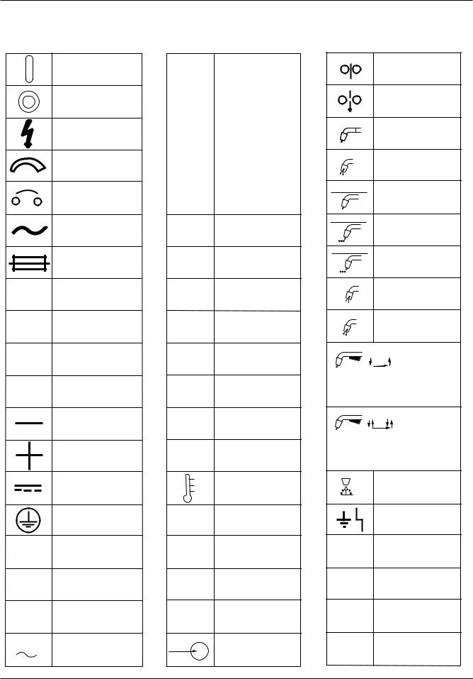
2.04 Symbol Chart
Note that only some of these symbols will appear on your model.
On
Off
Dangerous Voltage
Increase/Decrease
Circuit Breaker
AC Auxiliary Power
Fuse
Amperage
Voltage
Hertz (cycles/sec)
Frequency
Negative
Positive
Direct Current (DC)
Protective Earth (Ground)
Line
Line Connection
Auxiliary Power
115V 15A Receptacle Rating-
Auxiliary Power
|
Single Phase |
|
|
|
Three Phase |
|
|
|
Three Phase Static |
|
Frequency Converter- |
|
Transformer-Rectifier |
|
|
|
Remote |
|
|
X |
Duty Cycle |
%Percentage
Panel/Local
Shielded Metal
Arc Welding (SMAW)
Gas Metal Arc
Welding (GMAW)
Gas Tungsten Arc
Welding (GTAW)
Air Carbon Arc
Cutting (CAC-A)
Constant Current
Constant Voltage
Or Constant Potential
High Temperature
Fault Indication
Arc Force
Touch Start (GTAW)
Variable Inductance
V |
Voltage Input |
|
Wire Feed Function
Wire Feed Towards
Workpiece With
Output Voltage Off.
Welding Gun
Purging Of Gas
Continuous Weld
Mode
Spot Weld Mode
|
|
t |
Spot Time |
|
|
|
|
t1 |
|
|
Preflow Time |
|
t2 |
|
Postflow Time |
|
|
|
|
|
|
|
2 Step Trigger |
|
|
|
Operation |
Press to initiate wirefeed and welding, release to stop.
4 Step Trigger
Operation
Press and hold for preflow, release to start arc. Press to stop arc, and hold for preflow.
t |
Burnback Time |
Disturbance In
Ground System
IPM Inches Per Minute
MPM Meters Per Minute
Art # A-04130
2-2 |
July 27, 2005 |
HMC-410
2.05 General Information
The HMC-410 is an automatic/semiautomatic control panel capable of precisely controlling a power source (welding machine), wire feed motor, gas valve solenoid, and if present an automatic fixture. The HMC-410 can be controlled from the front panel or remotely through an optional remote pendant assembly, optional auxiliary interface cable, or optional robotic interface (see HMC410 Accessories And Option Descriptions chapter for more details). The functional capability of the HMC-410 can be changed to meet more specific customer applications by changing the system’s software. The HMC410 divides the weld process (schedule) into ready, preflow, run in, weld, crater fill, burnback, post-flow, and recycle segments. The user can program the appropriate parameters (time, voltage, and wire feed speed) into each segment. The HMC410 can store up to 10 weld schedules in nonvolatile memory (schedules are saved even with input power removed)
The HMC-410 comes with an abundance of standard features which include:
•an on/off rocker switch with built-in circuit breaker for total system protection
•a weld/program key switch for operator lockout
•an inch switch
•a purge switch
•a test mode switch allowing a run through of a programmed weld sequence setup without welding
•continuous-turn encoders for precise parameter input
•numerous LED displays for visual indication of parameters and modes
•a special soft switch screen allowing custom programming of system capabilities
•software upgrades to tailor the performance and capability of the system
•a self-diagnostics routine to aid in servicing
•a remote pendant amphenol input
•an auxiliary amphenol input for connection to PLC controllers or other fixturing
•a tachometer feedback control loop for precise wire feed speed control
•onboard fuses for system protection
•a ground fault circuit to protect the operator and equipment from welding current flowing through the ground system of the control panel
•a solid state circuit providing current limit to the wire feed motor
•a solid state dynamic brake.
The HMC-410 has been designed to comply with CSA NRTL/C, NEMA EW 3, and CE (IEC974-5) standards.
2.06 Product Specifications
HMC-410 Specifications
Input Voltage: |
120 VAC |
|
Input Frequency: |
50/60 Hz |
|
Input Voltage Tolerance |
±10% |
|
Maximum Input Current |
4.0 Amps |
|
Number of Weld Schedules |
10 |
|
Number of Weld Sub Segments |
4 |
|
(per Schedule) |
||
|
||
|
|
|
Maximum Auxilliary Relay Rating |
4 |
|
Approvals |
CSA NRTL/C |
|
|
NEMA EW 3 |
|
|
CE (IEC974-5) |
Table 2-1: Specification Chart
Refer to sheet 2 of the System Outline Drawing (number 170921) in the Appendix section of this manual for dimensional information.
July 27, 2005 |
2-3 |

HMC-410
|
|
HMC-410 Features & Benefits |
||
Features |
Benefits |
|||
|
|
|
A. Provides input voltage compensation |
|
1. |
|
Solid State Circuitry |
B. Provides current limit to the motor |
|
|
|
|
C. Provides overcurrent shutdown |
|
2. |
Tachometer Feedback |
A. Provides precise wire feed speed accuracy |
||
B. Provides motor load compensation |
||||
|
|
|
||
3. |
Continuous-Turn Encoders |
A. Allows precise input of welding parameters |
||
4. |
Multiple LED Displays |
A. Provides visual indication of parameter input |
||
5. |
Inch Switch |
A. Allows “cold” inching of wire at set wire feed speed |
||
6. |
Purge Switch |
A. Allows purging of gas without running wire |
||
7. |
Test Switch |
A. Permits a practice run through of a programmed weld |
||
sequence without welding |
||||
|
|
|
||
8. |
|
Keyswitch |
A. Provides operator lockout to preset welding parameters |
|
|
|
|
|
|
|
|
|
A. Operator can store up to 10 weld schedules into non- |
|
9. |
10 Weld Schedules |
volatile memory for easy job changeover |
||
B. Eliminates the need for continuous resetting of weld |
||||
|
|
|
||
|
|
|
parameters |
|
10. |
Soft Switch Screen |
A. Allows custom programming of system capabilities |
||
11. |
Self-Diagnostics Routine |
A. Aids in troubleshooting and servicing |
||
12. |
Multiple Software Upgrades |
A. Permits a reconfiguration of system capabilities with a |
||
simple change in software |
||||
|
|
|
||
13. |
Remote Pendant Amphenol |
A. Provides a connection point for the use of a remote |
||
pendant control |
||||
|
|
|
||
|
|
|
A. Allows an easy interface to PLC’s or similar controllers |
|
14. |
Auxiliary Interface Amphenol |
B. Provides 3 system relays that can be used to provide |
||
|
|
|
timing signals to PLC controllers |
|
15. |
Dynamic Brake |
A. Solid state control of a motor brake offers precise |
||
stopping of the wire |
||||
|
|
|
||
16. |
Input Circuit Breaker |
A. Provides total system protection |
||
17. |
On-Board Fuses |
A. Provides I/O protection |
||
|
|
|
A. Protects the operator and equipment from welding |
|
18. |
Ground Fault Circuit |
current flowing through the ground system of the control |
||
|
|
|
panel |
|
19. |
100% Duty Cycle |
A. Eliminates nuisance shutdowns due to overtemperature |
||
|
|
|
||
20. |
Small Size/Light Weight |
A. Takes up small amount of space |
||
Table 2-2: Features and Benefits
2-4 |
July 27, 2005 |

HMC-410
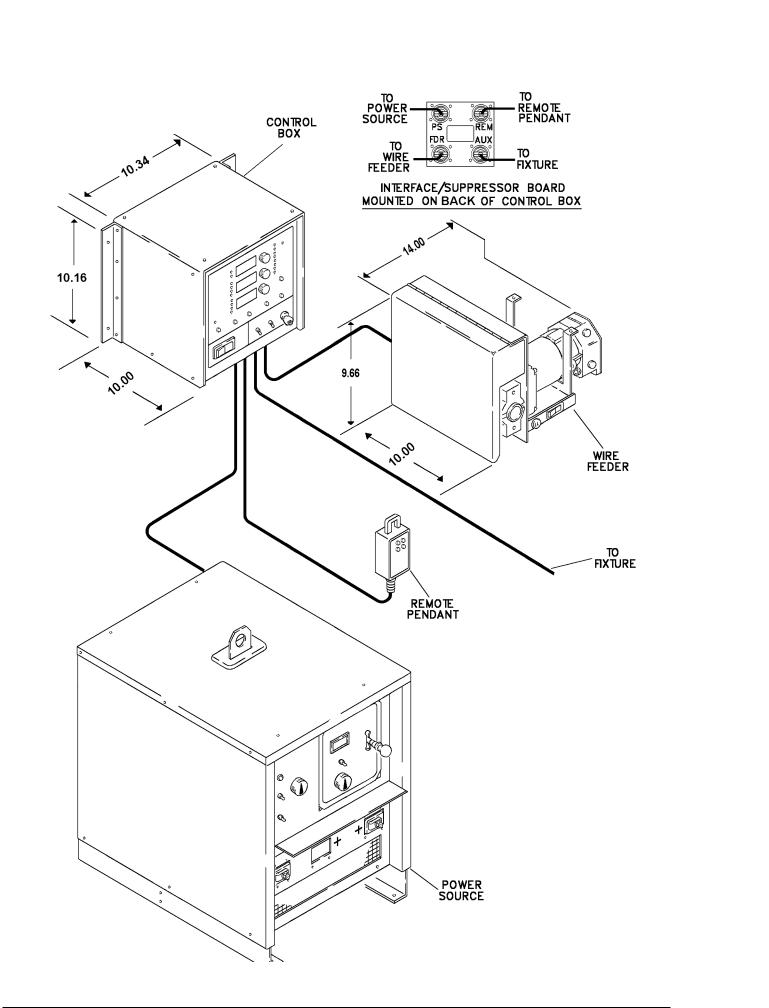
Art # A-04356
Figure 2-1A: Semiautomatic Configuration
July 27, 2005 |
2-5 |
Art # A-04357
Figure 2-1B: Automatic Configuration
2-6 |
July 27, 2005 |

HMC-410
2.07 Front Panel Controls
Refer to Figure 2-2 for details.
1.UPPER DISPLAY — This display shows numerical information for arc hours and time during normal operation. It can also contain diagnostic test information when diagnostics are performed.
2.ARC HOURS X100 LED—When lit, the upper display will display the number of “hundreds of hours” the control panel has controlled an arc. This number must be added to the number of hours in the center display for a total count of arc hours.
3.IME LED — When lit, the upper display will contain the time, in seconds, of the selected segment.
4.ARC HOURS X1 LED — When lit, the center display will show the number of hours the control panel has controlled an arc. This number must be added to the number of “hundreds of hours” in the upper display for a total count of arc hours.
5.VOLTS LED —When lit, the center display will show arc voltage. If the unit is being programmed, this number represents the programmed arc voltage. If the system is welding, this number is the actual arc voltage.
NOTE
If the PSC softswitch is off, this LED will not light. Refer to the Operation - Softswitch Description chapter of this manual.
6.COUNT LED—When lit, the center display will represent the number of weld sequence recycles. The number displayed is the number of times the weld sequence will repeat itself automatically. This number can be 1 to 255.
7.PROG DELAY LED — When lit, the center display will display the user selected programmable fault delay in seconds.
NOTE
Refer to the Operation - Softswitch Description chapter of this manual.
8.CENTER DISPLAY — This display shows numerical information for arc hours, volts, count, and prog delay during normal operation. It can also contain diagnostic test information when diagnostics are performed.
9.SCHEDULE NUMBER LED — When lit, the lower display will contain the schedule number currently active.
Figure 2-2: Front Panel Controls
July 27, 2005 |
2-7 |

HMC-410
10.AMPS LED — When lit, the lower display will show actual weld current in amps.
NOTE
To have the lower display show amps instead of wire feed speed, the mode select encoder will have to be turned.
11.WFS LED — When lit, the lower display shows the wire feed speed. If the unit is being programmed, this number represents the programmed wire feed speed. If the system is welding, the value displayed is actual wire feed speed.
NOTE
The unit comes from the factory with the WFS displayed in inches per minute (IPM). The WFS can be displayed in meters per minute (MPM). Refer to the Operation - Softswitch Description chapter of this manual.
12.WELD SUB SEGMENT LED — When lit, the lower display contains the current weld sub segment number. The weld sub segment number may be from 1 to 4. The system must be configured for weld sub segment operation for this to be selectable.
NOTE
Refer to the Operation - Softswitch Description chapter of this manual.
13.LOWER DISPLAY — This display shows numerical information for schedule number, amps, WFS, and weld sub segment during normal operation. It can also contain diagnostic test information when diagnostic are performed.
14.TEST LED — When lit, the control panel is in a test mode. The test mode allows the weld operator to perform the weld schedule with all of its control signals, timing, and displayed voltages and wire feed speeds. However the wire feeder and power source will not operate.
15.TEST BUTTON — This button will toggle the control panel in and out of test mode. This button has no effect during a weld.
16.PURGE BUTTON — Depressing the purge button will allow shielding gas to flow out of the welding gun without feeding wire. This button has no effect during a weld.
Figure 2-2: Front Panel Controls
2-8 |
July 27, 2005 |

HMC-410
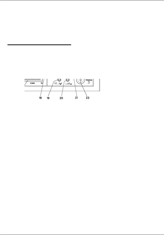
17.POWER ON/OFF SWITCH — This switch controls only the control panel and not the power source (welding machine). It is used as an on/off switch and also serves as a circuit breaker. NOTE: If the circuit breaker trips, it turns the power switch to the OFF position. A short cooling period must be allowed before an attempt is made to reset the unit by placing the switch in the ON position.
18.INCH BUTTON—Depressing the inch button will feed wire (without the flow of gas) at a speed programmed into the Run In section of the weld schedule; the welding wire WILL NOT be electrically “hot”. This button has no effect during a weld.
19.TRIGGER HOLD SWITCH (OPTIONAL) — This optional switch selects either 2 Step or 4 Step gun switch mode of operation for semiautomatic applications (to change the operation of this switch, refer to the Operation - Softswitch Description chapter of this manual). A detailed theory of operation for both modes of operation is given in the Operation chapter of this manual.
20.SUB SEGMENT ENABLE SWITCH (OPTIONAL) — This optional switch disables or enables the sub segment mode of operation for semiautomatic applications (to change the operation of this switch, refer to the Operation - Softswitch Description chapter of this manual). A detailed theory of operation for the sub segment mode of operation is given in the Operation chapter of this manual.
21.CYCLE START BUTTON — This button is used to start the weld cycle. When pressed, the control panel advances to the preflow section of the weld cycle. Depressing this button while in a weld cycle has no effect.
22.PROGRAM/WELD SWITCH — When this switch is in the program mode, weld parameters can be changed. When this switch is in the weld mode, weld parameters cannot be changed.
NOTE
The functionality of this switch can be changed in the softswitch screen and/or with different software upgrades. Refer to the Operation and Option chapters of this manual for further detail.
23.CYCLE STOP BUTTON—This button is used to stop a front panel initiated weld cycle. When pressed, the control panel leaves the weld section and enters the crater fill section of the weld cycle. When a weld is stopped with the cycle stop button, the control panel skips over the recycle section of the weld cycle.
NOTE
Depressing this button ONLY stops the weld cycle if the weld cycle was started with the cycle start button. This button WILL NOT stop a weld cycle that was started with a gun switch closure, remote pendant, or auxiliary fixture.
24.LOWER ENCODER—This encoder changes parameters displayed in the lower display. Turning this encoder clockwise increases the value of the parameter and counterclockwise decreases the value of the parameter.
25.MODE SELECT ENCODER — This encoder serves two functions. While not welding, the encoder selects the desired section of the weld cycle for parameter input and viewing. While welding, the encoder selects whether actual wire feed speed (WFS) or actual welding current (AMPS) is shown in the lower display.
26.RECYCLE LED — When lit, the control panel is in the recycle section of the weld cycle.
27.POST-FLOW LED—When lit, the control panel is in the post-flow section of the weld cycle.
28.BURNBACK LED—When lit, the control panel is in the burnback section of the weld cycle.
29.CRATER FILL LED — When lit, the control panel is in the crater fill section of the weld cycle.
30.WELD LED — When lit, the control panel is in the weld section of the weld cycle.
31.RUN IN LED — When lit, the control panel is in the run in section of the weld cycle.
32.Preflow LED — When lit, the control panel is in the preflow section of the weld cycle.
33.READY LED — When lit, the control panel is in the ready section of the weld cycle.
34.CENTER ENCODER — This encoder changes parameters displayed in the center display. Turning this encoder clockwise increases the value of the parameter and counterclockwise decreases the value of the parameter.
NOTE
The (Arc Hours X1) information cannot be changed with the center encoder. To reset the count to 0, refer to the Operation - Softswitch Description chapter of this manual.
July 27, 2005 |
2-9 |
HMC-410
35.ERROR LED—When lit, the control panel has detected an error. Refer to the Operation - Operational Faults section of this manual.
36.UPPER ENCODER — This encoder changes parameters displayed in the upper display. Turning this encoder clockwise increases the value of the parameter and counterclockwise decreases the value of the parameter.
NOTE
The (Arc Hours X100) information cannot be changed with the upper encoder. To reset the count to 0, refer to the Operation - Softswitch Description chapter of this manual.
Figure 2-2: Front Panel Controls
2-10 |
July 27, 2005 |

HMC-410
2.08 Rear Panel Connections
Refer to Figure 2-3 for details.
Remote Pendant
(See HMC-410 Accessories
And Option Descriptions)
37 |
39 |
38
Art # A-04359
Figure 2-3: Rear Panel Connections
37.POWER SOURCE AMPHENOL—This 19 pin male amphenol serves as the interface between the HMC410 and power source. A control cable will have to be connected between this amphenol and the 19 pin amphenol on the power source (Refer to the HMC410 Accessories And Option Descriptions chapter of this manual for control cable part numbers). The HMC410 utilizes the following pins of the 19 pin amphenol:
Pin
Assignment Function
APower Source Contactor Input
BPower Source Contactor Output
CArc Volts (+)
DArc Amps (+)
E120 VAC High
F120 VAC Neutral
GChassis Ground
J |
Remote Voltage Control Reference |
LPower Source Control Circuit Common
MArc Established Signal Input
UArc Amps (+)
VArc Volts (-)
NOTE
These pin assignments are for the HMC-410 only. Power source amphenol pin assignments will differ slightly (Refer to the power source owner’s manual for details).
38.FEEDHEAD AMPHENOL — This 19 pin female amphenol serves as the interface between the HMC410 and feedhead assembly. A control cable will have to be connected between this amphenol and the 19 pin amphenol on the feedhead assembly (refer to the HMC-410 Accessories And Option Descriptions chapter of this manual for control cable part numbers). The HMC-410 utilizes the following pins of the 19 pin amphenol:
Pin
Assignment Function
A(-) Motor Voltage
B(+) Motor Voltage
CInch Enable Out
DGun Switch Enable In
FInch Enable In
GChassis Ground
J |
Gas Valve Lo |
MTachometer Common
NTachometer (+15 VDC)
P |
Tachometer Feedback Signal |
T |
Gas Valve High |
V Gun Switch Enable Out
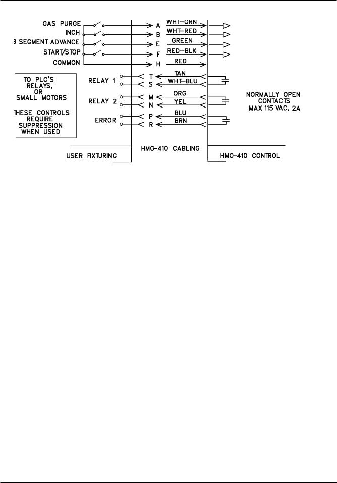
39.AUXILIARY AMPHENOL—If used, this 19 pin male amphenol would serve as the interface between the HMC-410 and appropriate external fixture. An auxiliary cable would have to be connected between this amphenol and the fixture (Refer to the HMC-410 Accessories And Option Descriptions chapter of this
manual for auxiliary cable part numbers).
This amphenol would only be used in an automatic application where the HMC-410 was to be controlled from some type of external fixture. Through this interface, the control panel accepts start, stop, inch, purge, and sub segment advance commands from the fixture and provides relay outputs to the fixture for timing and error conditions. The HMC-410 utilizes the following pins of the 19 pin amphenol (refer to Figure 3-4 for graphical assistance).
July 27, 2005 |
2-11 |
HMC-410
Art # A-04360
Figure 2-4: Fixture Electrical Interface
Pin A (Purge Input) —If connected to Pin H, the control panel will allow the flow of gas without running wire.
Pin B (Inch Input) — If connected to Pin H, the control panel will feed wire (without the flow of gas) at a speed programmed into the Run In section of the weld cycle; the welding wire WILL NOT be electrically “hot.”
Pin E (Sub Segment Advance Input) — Connecting (momentarily or permanently) to Pin H will advance the control panel to the next programmed weld sub segment (i.e. 1 to 2, 2 to 3, 3 to 4, and 4 to 1). However, if permanently connecting Pin E to Pin H, the connection will have to be momentarily opened and then closed again for another sub segment advance. Refer to the Operation - Auxiliary Interface Operation or Semiautomatic Operation section of this manual for specific details on setup and operation of the sub segment feature.
Pin F (Start/Stop Input)— To start the weld cycle, connect to Pin H. The control panel will then cycle from preflow to weld. To stop the weld cycle, disconnect from Pin H. The control panel will then leave weld and cycle from crater fill to ready.
Pin H (Common) — This pin serves as the common for pins A, B, E, and F.
Pins M and N (Relay 2) — This relay is normally open. When the control is in the recycle segment in between spot welds or at end of continuous weld, the relay will close (between pins M and N).
Pins P and R (Error Relay)—This relay is normally open. When the control detects a tolerance or ground fault, the relay will close (between pins P and R). The relay will remain closed for the duration of the weld in which the fault occurred, and .1 second into Ready. This relay can be used to drive another relay to latch the occurrence of an error. A tolerance fault can be one of: arc voltage out of tolerance, wire feed speed out of tolerance, or loss of arc established. The tolerance fault is reset when a new weld is initiated.
Pins T and S (Relay 1) — This relay is normally open. When the control is in the weld segment, the relay will close (shorting pins T and S). This relay is used for an arc on condition.
2-12 |
July 27, 2005 |
 Loading...