


 Loading...
INVERTER
ARC
WELDER
MODEL 185TSW AC/DC CC
STICK
TIG - Lift Start HF START
OPERATING MANUAL
November 13, 2003 |
Manual No. 430429-503 |
CONTENTS |
|
|
SYMBOL LEGEND ....................................................................................................................................................... |
5 |
|
STATEMENT OF WARRANTY ................................................................................................................................... |
6 |
|
1.0 GENERAL INFORMATION.................................................................................................................................... |
7 |
|
1.01 |
Notes, Cautions and Warnings ........................................................................................................................... |
7 |
1.02 |
Important Safety Precautions.............................................................................................................................. |
7 |
1.03 |
Publications ........................................................................................................................................................ |
8 |
1.04 |
Note, Attention et Avertissement........................................................................................................................ |
9 |
1.05 |
Precautions De Securite Importantes.................................................................................................................. |
9 |
1.06 |
Documents De Reference ................................................................................................................................. |
11 |
2.0 INTRODUCTION AND DESCRIPTION .............................................................................................................. |
13 |
|
2.01 |
Description ........................................................................................................................................................ |
13 |
2.02 |
Functional Block Diagrams ............................................................................................................................... |
14 |
2.03 |
Transporting Methods........................................................................................................................................ |
14 |
3.0 Installation Recommendations................................................................................................................................. |
15 |
|
3.01 |
Environment ...................................................................................................................................................... |
15 |
3.02 |
Location............................................................................................................................................................. |
15 |
3.03 |
Electrical Input Connections.............................................................................................................................. |
16 |
3.03.01 Electrical Input Requirements .................................................................................................................. |
16 |
|
3.03.02 Input Power .............................................................................................................................................. |
18 |
|
3.03.03 High Frequency Introduction.................................................................................................................... |
19 |
|
3.03.04 High Frequency Interference .................................................................................................................... |
19 |
|
3.04 |
Specifications .................................................................................................................................................... |
20 |
3.05 |
Duty Cycle......................................................................................................................................................... |
21 |
4.0 OPERATOR CONTROLS ...................................................................................................................................... |
23 |
|
4.01 Pro-Wave 185TSW Controls............................................................................................................................. |
23 |
|
4.02 |
Weld Process selection for Pro-Wave 185TSW ................................................................................................ |
25 |
4.03 |
Weld Parameter Descriptions for Pro-Wave 185TSW ...................................................................................... |
26 |
4.04 Weld Parameters for Pro-Wave 185TSW.......................................................................................................... |
28 |
|
4.05 |
Power Source Features ...................................................................................................................................... |
29 |
5.0 SET-UP FOR SMAW (STICK) AND GTAW (TIG) ............................................................................................. |
31 |
|
6.0 SEQUENCE OF OPERATION............................................................................................................................... |
32 |
|
6.01 |
Stick Welding .................................................................................................................................................... |
33 |
6.02 AC or DC HF TIG Welding .............................................................................................................................. |
34 |
|
6.02.01 Slope Mode Sequence .............................................................................................................................. |
35 |
|
6.02.02 Slope Mode with repeat sequence ............................................................................................................ |
35 |
|
6.02.03 Pulse Controls........................................................................................................................................... |
36 |
|
7.0 BASIC TIG WELDING GUIDE............................................................................................................................. |
37 |
|
7.01 |
Explanation of “Fluttery Arc” when AC TIG Welding on Aluminum.............................................................. |
37 |
7.02 |
Electrode Polarity .............................................................................................................................................. |
38 |
7.03 |
Tungsten Electrode Current Ranges .................................................................................................................. |
38 |
7.04 |
Tungsten Electrode Types ................................................................................................................................. |
38 |
7.05 |
Guide for Selecting Filler Wire Diameter.......................................................................................................... |
39 |
7.06 |
Shielding Gas Selection..................................................................................................................................... |
39 |
7.07 |
TIG Welding Parameters for Low Carbon & Low Alloy Steel Pipe ................................................................. |
39 |
7.08 |
Welding Parameters for Aluminum................................................................................................................... |
40 |
7.09 |
Welding Parameters for Steel ............................................................................................................................ |
40 |
8.0 Basic Arc Welding Guide........................................................................................................................................ |
41 |
|
8.01 |
Electrode Polarity .............................................................................................................................................. |
41 |
8.02 |
Effects of Stick Welding Various Materials ...................................................................................................... |
41 |
9.0 ROUTINE MAINTENANCE ................................................................................................................................. |
42 |
|
10.0 BASIC TROUBLESHOOTING............................................................................................................................ |
43 |
|
10.01 TIG Welding Problems.................................................................................................................................... |
43 |
|
10.02 Stick Welding Problems .................................................................................................................................. |
45 |
|
10.03 Power Source Problems................................................................................................................................... |
47 |
|
11.0 Voltage Reduction Device (VRD)......................................................................................................................... |
49 |
|
11.01 VRD Specification........................................................................................................................................... |
49 |
|
11.02 VRD Maintenance ........................................................................................................................................... |
49 |
|
12.0 Power Source Error Codes .................................................................................................................................... |
50 |
|
3
13.0 PARTS LIST......................................................................................................................................................... |
53 |
APPENDIX A – INTERCONNECT DIAGRAM ........................................................................................................ |
56 |
APPENDIX B - AUTOMATION................................................................................................................................. |
58 |
4

SYMBOL LEGEND
Amperage
Voltage
Hertz (frequency)
SEC Seconds
%Percent
DC (Direct Current)
AC (Alternating Current
Standard Function
Slope Function
Slope W/Repeat Function
Spot Function
Impulse Starting (High
Frequency GTAW)
Touch Start (Lift Start TIG circuit GTAW)
|
|
|
|
|
|
|
|
|
|
|
|
|
|
|
STICK (Shielded Metal Arc |
|
|
|
|
|
|
|
|
|
|
|
|
|
|
|
SMAW) |
|
|
|
|
|
|
|
|
|
|
|
|
|
|
|
|
|
|
|
|
|
|
|
|
|
|
|
|
|
|
|
|
|
|
|
|
|
|
|
|
|
|
|
|
|
|
|
Pulse Current Function |
|
|
|
|
|
|
|
|
|
|
|
|
|
|
|
|
|
|
|
|
|
|
|
|
|
|
|
|
|
|
|
Spot Time (GTAW) |
|
|
|
|
|
|
|
|
|
|
|
|
|
|
|
|
|
|
|
|
|
|
|
|
|
|
|
|
|
|
|
|
|
|
|
|
|
|
|
|
|
|
|
|
|
|
|
|
|
|
|
|
|
|
|
|
|
|
|
|
|
|
|
|
|
|
|
|
|
|
|
|
|
|
|
|
|
|
|
|
|
|
|
|
|
|
|
|
|
|
|
|
|
|
|
|
|
|
|
|
|
|
|
|
|
|
|
|
|
|
|
|
|
|
|
|
|
|
|
|
|
|
|
|
|
|
|
Remote Control (Panel/Remote) |
|
|
|
|
|
|
|
|
|
|
|
|
|
|
|
Remote Function |
|
|
|
|
|
|
|
|
|
|
|
|
|
|
|
|
|
|
|
|
|
|
|
|
|
|
|
|
|
|
|
Arc Control (SMAW) |
|
|
|
|
|
|
|
|
|
|
|
|
|
|
|
Gas Post-Flow |
|
|
|
|
|
|
|
|
|
|
|
|
|
|
|
|
|
|
|
|
|
|
|
|
|
|
|
|
|
|
|
Gas Pre-Flow |
|
|
|
|
|
|
|
|
|
|
|
|
|
|
|
|
VRD |
Voltage Reduction Device |
||||||||||||||
Circuit |
|||||||||||||||
|
|
|
|
|
|
|
|
|
|
|
|
|
|
|
|
|
|
|
|
|
|
|
|
|
|
|
|
|
|
|
Negative |
|
|
|
|
|
|
|
|
|
|
|
|
|
|
|
|
|
|
|
|
|
|
|
|
|
|
|
|
|
|
|
Positive |
|
|
|
|
|
|
|
|
|
|
|
|
|
|
|
|
|
|
|
|
|
|
|
|
|
|
|
|
|
|
|
Gas Input |
|
|
|
|
|
|
|
|
|
|
|
|
|
|
|
|
|
|
|
|
|
|
|
|
|
|
|
|
|
|
|
Gas Output |
|
|
|
|
|
|
|
|
|
|
|
|
|
|
|
|
5
STATEMENT OF WARRANTY
LIMITED WARRANTY: Thermal Arc®, Inc., A Thermadyne Company, hereafter, “Thermal Arc” warrants to customers of its authorized distributors hereafter “Thermal; Arc” that its products will be free of defects in workmanship or material. Should any failure to conform to this warranty appear within the time period applicable to the Thermal Arc products as stated below, Thermal Arc shall, upon notification thereof and substantiation that the product has been stored, installed, operated, and maintained in accordance with Thermal Arc’s specifications, instructions, recommendations and recognized standard industry practice, and not subject to misuse, repair, neglect, alteration, or accident, correct such defects by suitable repair or replacement, at Thermal Arc’s sole option, of any components or parts of the product determined by Thermal Arc to be defective.
THERMAL ARC MAKES NO OTHER WARRANTY, EXPRESS OR IMPLIED. THIS WARRANTY IS EXCLUSIVE AND IN LIEU OF ALL OTHERS, INCLUDING, BUT NOT LIMITED TO ANY WARRANTY OF MERCHANTABILITY OR FITNESS FOR ANY PARTICULAR PURPOSE.
LIMITATION OF LIABILITY: Thermal Arc shall not under any circumstances be liable for special, indirect or consequential damages, such as, but not limited to, lost profits and business interruption. The remedies of the Purchaser set forth herein are exclusive and the liability of Thermal Arc with respect to any contract, or anything done in connection therewith such as the performance or breach thereof, or from the manufacture, sale, delivery, resale, or use of any goods covered by or furnished by Thermal Arc whether arising out of contract, negligence, strict tort, or under any warranty, or otherwise, shall not, except as expressly provided herein, exceed the price of the goods upon which such liability is based. No employee, agent, or representative of Thermal Arc is authorized to change this warranty in any way or grant any other warranty.
PURCHASER'S RIGHTS UNDER THIS WARRANTY ARE VOID IF REPLACEMENT PARTS OR ACCESSORIES ARE USED WHICH IN THERMAL ARC’S SOLE JUDGEMENT MAY IMPAIR THE SAFETY OR PERFORMANCE OF ANY THERMAL ARC PRODUCT.
PURCHASER'S RIGHTS UNDER THIS WARRANTY ARE VOID IF THE PRODUCT IS SOLD TO PURCHASER BY NONAUTHORIZED PERSONS.
The warranty is effective for the time stated below beginning on the date that the authorized distributor delivers the products to the Purchaser. Notwithstanding the foregoing, in no event shall the warranty period extend more than the time stated plus one year from the date Thermal Arc delivered the product to the authorized distributor.
POWER SUPPLIES |
POWER SUPPLIES & WIRE FEEDERS |
LABOR |
MAIN POWER MAGNETICS (STATIC & ROTATING) |
3 YEAR |
3 YEAR |
ORIGINAL MAIN POWER RECTIFIER |
3 YEAR |
3 YEAR |
POWER SWITCHING SEMI-CONDUCTORS & CONTROL PC BOARD |
3 YEAR |
3 YEAR |
ALL OTHER CIRCUITS AND COMPONENTS INCLUDING |
1 YEAR |
1 YEAR |
BUT NOT LIMITED TO, CONTACTORS, RELAYS, |
|
|
SOLENOIDS, PUMPS, SWITCHES, MOTORS |
|
|
ENGINES: ENIGINES ARE NOT WARRANTED BY THERMAL ARC, ALTHOUGH MOST ARE WARRANTED BY THE ENGINE MANUFACTURER, SEE THE ENGINE MANUFACTURES WARRANTY FOR DETAILS.
CONSOLES, CONTROL EQUIPMENT, HEAT |
1 YEAR |
1 YEAR |
EXCHANGES, AND ACCESSORY EQUIPMENT |
|
|
PLASMA TORCH AND LEADS, AND REMOTE CONTROLS |
180 DAYS |
180 DAYS |
REPAIR/REPLACEMENT PARTS |
90 DAYS |
90 DAYS |
Warranty repairs or replacement claims under this limited warranty must be submitted to Thermal Arc by an authorized Thermal Arc repair facility within thirty (30) days of purchaser’s notice of any Warranty Claim. No transportation costs of any kind will be paid under this warranty. Transportation charges to send products to an authorized warranty repair facility shall be the responsibility of the Purchaser. All returned goods shall be at the Purchaser’s risk and expense. This warranty supersedes all previous Thermal Arc warranties.
Thermal Arc® is a Registered Trademark of Thermadyne Industries Inc.
Effective April 1, 2002
6

1.0 GENERAL INFORMATION
1.01 Notes, Cautions and Warnings
Throughout this manual, notes, cautions, and warnings are used to highlight important information. These highlights are categorized as follows:
NOTE
An operation, procedure, or background information which requires additional emphasis or is helpful in efficient operation of the system.
 CAUTION
A procedure which, if not properly followed, may cause damage to the equipment.
 WARNING
A procedure which, if not properly followed, may cause injury to the operator or others in the operating area.
1.02 Important Safety Precautions
 WARNING
OPERATION AND
MAINTENANCE OF ARC
WELDING EQUIPMENT CAN BE
DANGEROUS AND HAZARDOUS
TO YOUR HEALTH.
To prevent possible injury, read, understand and follow all warnings, safety precautions and instructions before using the equipment. Call 1- 800-462-2782 or your local distributor if you have any questions.
GASES AND FUMES
Gases and fumes produced during the Arc welding/cutting process can be dangerous and hazardous to your health.
•Keep all fumes and gases from the breathing area. Keep your head out of the welding fume plume.
•Use an air-supplied respirator if ventilation is not adequate to remove all fumes and gases.
•The kinds of fumes and gases from the arc welding/cutting depend on the kind of metal being used, coatings on the metal, and the different processes. You must be very careful when cutting or welding any metals which may contain one or more of the following:
Antimony |
Chromium |
Mercury |
Arsenic |
Cobalt |
Nickel |
Barium |
Copper |
Selenium |
Beryllium |
Lead |
Silver |
Cadmium |
Manganese |
|
Vanadium |
|
|
•Always read the Material Safety Data Sheets (MSDS) that should be supplied with the material you are using. These MSDSs will give you the information regarding the kind and amount of fumes and gases that may be dangerous to your health.
•For information on how to test for fumes and gases in your workplace, refer to item 1 in Subsection 1.03, Publications in this manual.
•Use special equipment, such as water or down draft welding/cutting tables, to capture fumes and gases.
•Do not use the welding torch in an area where combustible or explosive gases or materials are located.
•Phosgene, a toxic gas, is generated from the vapors of chlorinated solvents and cleansers. Remove all sources of these vapors.
ELECTRIC SHOCK
Electric Shock can injure or kill. The arc welding process uses and produces high voltage electrical energy. This electric energy can cause severe or fatal shock to the operator or others in the workplace.
•Never touch any parts that are electrically “live” or “hot.”
•Wear dry gloves and clothing. Insulate yourself from the work piece or other parts of the welding circuit.
•Repair or replace all worn or damaged parts.
•Extra care must be taken when the workplace is moist or damp.
7

•Install and maintain equipment according to NEC code, refer to item 4 in Subsection 1.03, Publications.
•Disconnect power source before performing any service or repairs.
•Read and follow all the instructions in the Operating Manual.
FIRE AND EXPLOSION
Fire and explosion can be caused by hot slag, sparks, or the arc weld.
•Be sure there is no combustible or flammable material in the workplace. Any material that cannot be removed must be protected.
•Ventilate all flammable or explosive vapors from the workplace.
•Do not cut or weld on containers that may have held combustibles.
•Provide a fire watch when working in an area where fire hazards may exist.
ARC WELDING RAYS
Arc Welding/Cutting Rays can injure your eyes and burn your skin. The arc welding/cutting process produces very bright ultra violet and infra red light. These arc rays will damage your eyes and burn your skin if you are not properly protected.
•To protect your eyes, always wear a welding helmet or shield. Also always wear safety glasses with side shields, goggles or other protective eye wear.
•Wear welding gloves and suitable clothing to protect your skin from the arc rays and sparks.
•Keep helmet and safety glasses in good condition. Replace lenses when cracked, chipped or dirty.
•Protect others in the work area from the arc rays. Use protective booths, screens or shields.
•Use the shade of lens as recommended in Subsection 1.03, item 4.
• Hydrogen gas may be formed and trapped
under aluminum workpieces when they are1.03 Publications cut underwater or while using a water table.
DO NOT cut aluminum alloys underwater or on a water table unless the hydrogen gas can be eliminated or dissipated. Trapped hydrogen gas that is ignited will cause an explosion.
 NOISE
NOISE
Noise can cause permanent hearing loss. Arc welding/cutting processes can cause noise levels to exceed safe limits. You must protect your ears from loud noise to prevent permanent loss of hearing.
•To protect your hearing from loud noise, wear protective ear plugs and/or ear muffs. Protect others in the workplace.
•Noise levels should be measured to be sure the decibels (sound) do not exceed safe levels.
•For information on how to test for noise, see item 1 in Subsection 1.03, Publications, in this manual.
8

6.ANSI Standard Z49.2, FIRE PREVENTION IN THE USE OF CUTTING AND WELDING PROCESSES, obtainable from American National Standards Institute, 1430 Broadway, New York, NY 10018
7.AWS Standard A6.0, WELDING AND CUTTING CONTAINERS WHICH HAVE HELD COMBUSTIBLES, obtainable from American Welding Society, 550 N.W. LeJeune Rd, Miami, FL 33126
8.NFPA Standard 51, OXYGEN-FUEL GAS SYSTEMS FOR WELDING, CUTTING AND ALLIED PROCESSES, obtainable from the National Fire Protection Association, Batterymarch Park, Quincy, MA 02269
9.NFPA Standard 70, NATIONAL ELECTRICAL CODE, obtainable from the National Fire Protection Association, Batterymarch Park, Quincy, MA 02269
10.NFPA Standard 51B, CUTTING AND WELDING PROCESSES, obtainable from the National Fire Protection Association, Batterymarch Park, Quincy, MA 02269
11.CGA Pamphlet P-1, SAFE HANDLING OF COMPRESSED GASES IN CYLINDERS, obtainable from the Compressed Gas Association, 1235 Jefferson Davis Highway, Suite 501, Arlington, VA 22202
12.CSA Standard W117.2, CODE FOR SAFETY IN WELDING AND CUTTING, obtainable from the Canadian Standards Association, Standards Sales, 178 Rexdale Boulevard, Rexdale, Ontario, Canada M9W 1R3
13.NWSA booklet, WELDING SAFETY BIBLIOGRAPHY obtainable from the National Welding Supply Association, 1900 Arch Street, Philadelphia, PA 19103
14.American Welding Society Standard AWSF4.1, RECOMMENDED SAFE PRACTICES FOR THE PREPARATION FOR WELDING AND CUTTING OF CONTAINERS AND PIPING THAT HAVE HELD HAZARDOUS SUBSTANCES, obtainable from the American Welding Society, 550 N.W. LeJeune Rd, Miami, FL 33126
15.ANSI Standard Z88.2, PRACTICE FOR RESPIRATORY PROTECTION, obtainable from American National Standards Institute, 1430 Broadway, New York, NY 10018
1.04Note, Attention et Avertissement
Dans ce manuel, les mots “note,” “attention,” et “avertissement” sont utilisés pour mettre en relief
des informations à caractère important. Ces mises en relief sont classifiées comme suit :
NOTE
Toute opération, procédure ou renseignement général sur lequel il importe d’insister davantage ou qui contribue à l’efficacité de fonctionnement du système.
 ATTENTION
Toute procédure pouvant résulter l’endommagement du matériel en cas de non-respect de la procédure en question.
 AVERTISSEMENT
Toute procédure pouvant provoquer des blessures de l’opérateur ou des autres personnes se trouvant dans la zone de travail en cas de non-respect de la procédure en question.
1.05 Precautions De Securite
Importantes
 AVERTISSEMENT
L’OPÉRATION ET LA
MAINTENANCE DU MATÉRIEL
DE SOUDAGE À L’ARC AU JET
DE PLASMA PEUVENT
PRÉSENTER DES RISQUES ET
DES DANGERS DE SANTÉ.
Il faut communiquer aux opérateurs et au personnel TOUS les dangers possibles. Afin d’éviter les blessures possibles, lisez, comprenez et suivez tous les avertissements, toutes les précautions de sécurité et toutes les consignes avant d’utiliser le matériel. Composez le + 1-800-462-2782 ou votre distributeur local si vous avez des questions.
FUMÉE et GAZ
La fumée et les gaz produits par le procédé de jet de plasma peuvent présenter des risques et des dangers de santé.
9

•Eloignez toute fumée et gaz de votre zone de respiration. Gardez votre tête hors de la plume de fumée provenant du chalumeau.
•Utilisez un appareil respiratoire à alimentation en air si l’aération fournie ne permet pas d’éliminer la fumée et les gaz.
•Les sortes de gaz et de fumée provenant de l’arc de plasma dépendent du genre de métal utilisé, des revêtements se trouvant sur le métal et des différents procédés. Vous devez prendre soin lorsque vous coupez ou soudez tout métal pouvant contenir un ou plusieurs des éléments suivants:
antimoine |
cadmium |
mercure |
argent |
chrome |
nickel |
arsenic |
cobalt |
plomb |
baryum |
cuivre |
sélénium |
béryllium |
manganèse |
|
vanadium |
|
|
•Lisez toujours les fiches de données sur la sécurité des matières (sigle américain “MSDS”); celles-ci devraient être fournies avec le matériel que vous utilisez. Les MSDS contiennent des renseignements quant à la quantité et la nature de la fumée et des gaz pouvant poser des dangers de santé.
•Pour des informations sur la manière de tester la fumée et les gaz de votre lieu de travail, consultez l’article 1 et les documents cités à la page 5.
•Utilisez un équipement spécial tel que des tables de coupe à débit d’eau ou à courant descendant pour capter la fumée et les gaz.
•N’utilisez pas le chalumeau au jet de plasma dans une zone où se trouvent des matières ou des gaz combustibles ou explosifs.
•Le phosgène, un gaz toxique, est généré par la fumée provenant des solvants et des produits de nettoyage chlorés. Eliminez toute source de telle fumée.
CHOC ELECTRIQUE
Les chocs électriques peuvent blesser ou même tuer. Le procédé au jet de plasma requiert et produit de l’énergie électrique haute tension. Cette énergie électrique peut produire des chocs graves, voire mortels, pour l’opérateur et les autres personnes sur le lieu de travail.
•Ne touchez jamais une pièce “sous tension” ou “vive”; portez des gants et des vêtements
secs. Isolez-vous de la pièce de travail ou des autres parties du circuit de soudage.
•Réparez ou remplacez toute pièce usée ou endommagée.
•Prenez des soins particuliers lorsque la zone de travail est humide ou moite.
•Montez et maintenez le matériel conformément au Code électrique national des Etats-Unis. (Voir la page 5, article 9.)
•Débranchez l’alimentation électrique avant tout travail d’entretien ou de réparation.
•Lisez et respectez toutes les consignes du Manuel de consignes.
INCENDIE ET EXPLOSION
Les incendies et les explosions peuvent résulter des scories chaudes, des étincelles ou de l’arc de plasma. Le procédé à l’arc de plasma produit du métal, des étincelles, des scories chaudes pouvant mettre le feu aux matières combustibles ou provoquer l’explosion de fumées inflammables.
•Soyez certain qu’aucune matière combustible ou inflammable ne se trouve sur le lieu de travail. Protégez toute telle matière qu’il est impossible de retirer de la zone de travail.
•Procurez une bonne aération de toutes les fumées inflammables ou explosives.
•Ne coupez pas et ne soudez pas les conteneurs ayant pu renfermer des matières combustibles.
•Prévoyez une veille d’incendie lors de tout travail dans une zone présentant des dangers d’incendie.
•Le gas hydrogène peut se former ou s’accumuler sous les pièces de travail en aluminium lorsqu’elles sont coupées sous l’eau ou sur une table d’eau. NE PAS couper les alliages en aluminium sous l’eau ou sur une table d’eau à moins que le gas hydrogène peut s’échapper ou se dissiper. Le gas hydrogène accumulé explosera si enflammé.
 RAYONS D’ARC DE PLASMA
Les rayons provenant de l’arc de plasma peuvent blesser vos yeux et brûler votre peau. Le procédé à l’arc de plasma produit une lumière infra-rouge et des rayons ultra-violets très forts. Ces rayons d’arc
10
nuiront à vos yeux et brûleront votre peau si vous ne vous protégez pas correctement.
•Pour protéger vos yeux, portez toujours un casque ou un écran de soudeur. Portez toujours des lunettes de sécurité munies de parois latérales ou des lunettes de protection ou une autre sorte de protection oculaire.
•Portez des gants de soudeur et un vêtement protecteur approprié pour protéger votre peau contre les étincelles et les rayons de l’arc.
•Maintenez votre casque et vos lunettes de protection en bon état. Remplacez toute lentille sale ou comportant fissure ou rognure.
•Protégez les autres personnes se trouvant sur la zone de travail contre les rayons de l’arc en fournissant des cabines ou des écrans de protection.
•Respectez le teint de lentille recommandé dans le article 4, page 5.
•Hydrogen gas may be present under aluminum workpieces during the cutting process when being cut underwater or using a water table. DO NOT cut aluminum underwater or on a water table unless the hydrogen gas can be eliminated as the hydrogen gas may detonate.
 BRUIT
BRUIT
Le bruit peut provoquer une perte permanente de l’ouïe. Les procédés de soudage à l’arc de plasma peuvent provoquer des niveaux sonores supérieurs aux limites normalement acceptables. Vous dú4ez vous protéger les oreilles contre les bruits forts afin d’éviter une perte permanente de l’ouïe.
•Pour protéger votre ouïe contre les bruits forts, portez des tampons protecteurs et/ou des protections auriculaires. Protégez également les autres personnes se trouvant sur le lieu de travail.
•Il faut mesurer les niveaux sonores afin d’assurer que les décibels (le bruit) ne dépassent pas les niveaux sûrs.
•Pour des renseignements sur la manière de tester le bruit, consultez l’article 1, page 5.
1.06 Documents De Reference
Consultez les normes suivantes ou les révisions les plus récentes ayant été faites à celles-ci pour de plus amples renseignements :
1.OSHA, NORMES DE SÉCURITÉ DU TRAVAIL ET DE PROTECTION DE LA SANTÉ, 29CFR 1910, disponible auprès du Superintendent of Documents, U.S. Government Printing Office, Washington, D.C. 20402
2.Norme ANSI Z49.1, LA SÉCURITÉ DES OPÉRATIONS DE COUPE ET DE SOUDAGE, disponible auprès de la Société Américaine de Soudage (American Welding Society), 550 N.W. LeJeune Rd., Miami, FL 33126
3.NIOSH, LA SÉCURITÉ ET LA SANTÉ LORS DES OPÉRATIONS DE COUPE ET DE SOUDAGE À L’ARC ET AU GAZ, disponible auprès du Superintendent of Documents, U.S. Government Printing Office, Washington, D.C. 20402
4.Norme ANSI Z87.1, PRATIQUES SURES POUR LA PROTECTION DES YEUX ET DU VISAGE AU TRAVAIL ET DANS LES ECOLES, disponible de l’Institut Américain des Normes Nationales (American National Standards Institute), 1430 Broadway, New York, NY 10018
5.Norme ANSI Z41.1, NORMES POUR LES CHAUSSURES PROTECTRICES, disponible auprès de l’American National Standards Institute, 1430 Broadway, New York, NY 10018
6.Norme ANSI Z49.2, PRÉVENTION DES INCENDIES LORS DE L’EMPLOI DE PROCÉDÉS DE COUPE ET DE SOUDAGE, disponible auprès de l’American National Standards Institute, 1430 Broadway, New York, NY 10018
7.Norme A6.0 de l’Association Américaine du Soudage (AWS), LE SOUDAGE ET LA COUPE DE CONTENEURS AYANT RENFERMÉ DES PRODUITS COMBUSTIBLES, disponible auprès de la American Welding Society, 550 N.W. LeJeune Rd., Miami, FL 33126
8.Norme 51 de l’Association Américaine pour la Protection contre les Incendies (NFPA), LES SYSTEMES À GAZ AVEC ALIMENTATION EN OXYGENE POUR LE SOUDAGE, LA COUPE ET LES PROCÉDÉS
11
ASSOCIÉS, disponible auprès de la National Fire Protection Association, Batterymarch Park, Quincy, MA 02269
9.Norme 70 de la NFPA, CODE ELECTRIQUE NATIONAL, disponible auprès de la National Fire Protection Association, Batterymarch Park, Quincy, MA 02269
10.Norme 51B de la NFPA, LES PROCÉDÉS DE COUPE ET DE SOUDAGE, disponible auprès de la National Fire Protection Association, Batterymarch Park, Quincy, MA 02269
11.Brochure GCA P-1, LA MANIPULATION SANS RISQUE DES GAZ COMPRIMÉS EN CYLINDRES, disponible auprès de l’Association des Gaz Comprimés (Compressed Gas Association), 1235 Jefferson Davis Highway, Suite 501, Arlington, VA 22202
12.Norme CSA W117.2, CODE DE SÉCURITÉ POUR LE SOUDAGE ET LA COUPE, disponible auprès de l’Association des Normes Canadiennes, Standards Sales, 178 Rexdale Boulevard, Rexdale, Ontario, Canada, M9W 1R3
13.ivret NWSA, BIBLIOGRAPHIE SUR LA SÉCURITÉ DU SOUDAGE, disponible auprès de l’Association Nationale de Fournitures de Soudage (National Welding Supply Association), 1900 Arch Street, Philadelphia, PA 19103
14.Norme AWSF4.1 de l’Association Américaine de Soudage, RECOMMANDATIONS DE PRATIQUES SURES POUR LA PRÉPARATION À LA COUPE ET AU SOUDAGE DE CONTENEURS ET TUYAUX AYANT RENFERMÉ DES PRODUITS DANGEREUX , disponible auprès de la American Welding Society, 550 N.W. LeJeune Rd., Miami, FL 33126
15.Norme ANSI Z88.2, PRATIQUES DE PROTECTION RESPIRATOIRE, disponible auprès de l’American National Standards Institute, 1430 Broadway, New York, NY 10018
12
2.0 INTRODUCTION AND DESCRIPTION
2.01 Description
The Thermal Arc™ Model 185TSW is a self contained single-phase AC/DC arc welding power source with Constant Current (CC) output characteristics. This unit is equipped with a Digital Volt/Amperage Meter, gas control valve, built in Sloper and Pulser, lift arc starter, and high-frequency arc starter for use with Gas Tungsten Arc Welding (GTAW), Gas Tungsten Arc Welding-Pulsed (GTAW-P) Gas Tungsten Arc Welding-Sloped (GTAW-S), and Shielded Metal Arc Welding (SMAW) processes. The power source is totally enclosed in an impact resistant, flame retardant and non-conductive plastic case.
(V) OCV
5A |
160A (A) |
|
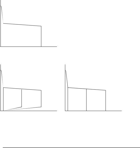
STICK Process |
(V) |
(V) |
OCV |
OCV |
10V
25A |
185A |
(A) |
5A |
185A |
(A) |
|
LIFT TIG Process |
|
|
HF TIG Process |
|
Figure 1. Model 185TSW Volt-Ampere curve
Note 1
Volt-Ampere curves show the maximum Voltage and Amperage output capabilities of the welding power source. Curves of other settings will fall between the curves shown.
13

2.02 Functional Block Diagrams
Figure 2 illustrates the functional block diagram of the 185TSW-power supply.
Figure 2. 185TSW Model Functional Block Diagram
2.03 Transporting Methods
These units are equipped with a handle for carrying purposes.
 WARNING 1
ELECTRIC SHOCK can kill. DO NOT TOUCH live electrical parts. Disconnect input power conductors from de-energized supply line before moving the welding power source.
 WARNING 2
FALLING EQUIPMENT can cause serious personal injury and equipment damage.
Lift unit with handle on top of case.
Use handcart or similar device of adequate capacity.
If using a fork lift vehicle, place and secure unit on a proper skid before transporting.
14

3.0 Installation Recommendations
3.01 Environment
The Pro-Wave 185TSW is designed for use in hazardous environments.
Examples of environments with increased hazardous environments are -
a)In locations in which freedom of movement is restricted, so that the operator is forced to perform the work in a cramped (kneeling, sitting or lying) position with physical contact with conductive parts;
b)In locations which are fully or partially limited by conductive elements, and in which there is a high risk of unavoidable or accidental contact by the operator, or
c)In wet or damp hot locations where humidity or perspiration considerably reduces the skin resistance of the human body and the insulation properties of accessories.
Environments with hazardous environments do not include places where electrically conductive parts in the near vicinity of the operator, which can cause increased hazard, have been insulated.
3.02 Location
Be sure to locate the welder according to the following guidelines:
• |
In areas, free from moisture and dust. |
• |
Ambient temperature between 0 degrees C |
|
|
|
to 40 degrees C. |
• |
In areas, free from oil, steam and • |
In areas, not subjected to abnormal |
|
|
corrosive gases. |
|
vibration or shock. |
• |
In areas, not exposed to direct sunlight or |
• |
Place at a distance of 12” (304.79mm) or |
|
rain. |
|
more from walls or similar that could |
|
|
|
restrict natural airflow for cooling. |
 WARNING 3
Thermal Arc advises that this equipment be electrically connected by a qualified electrician.
15

3.03 Electrical Input Connections
 WARNING 4
ELECTRIC SHOCK can kill; SIGNIFICANT DC VOLTAGE is present after removal of input power.
DO NOT TOUCH live electrical parts.
SHUT DOWN welding power source, disconnect input power employing lockout/tagging procedures. Lockout/tagging procedures consist of padlocking line disconnect switch in open position, removing fuses from fuse box, or shutting off and red-tagging circuit breaker or other disconnecting device.
3.03.01 Electrical Input Requirements
Operate the welding power source from a single-phase 50/60 Hz, AC power supply. The input voltage must match one of the electrical input voltages shown on the input data label on the unit nameplate. Contact the local electric utility for information about the type of electrical service available, how proper connections should be made, and any inspection required.
The line disconnect switch provides a safe and convenient means to completely remove all electrical power from the welding power supply whenever necessary to inspect or service the unit.
Note 2
These units are equipped with a two-conductor with earth power cable that is connected at the welding power source end for single-phase electrical input power.
Do not connect an input (WHITE or BLACK) conductor to the ground terminal. Do not connect the ground (GREEN) conductor to an input line terminal.
Refer to figure 3 and:
1.Connect end of ground (GREEN) conductor to a suitable ground. Use a grounding method that complies with all applicable electrical codes.
2.Connect ends of line 1 (BLACK) and line 2 (WHITE) input conductors to a de-energized line disconnect switch.
3.Use Table 1 and Table 2 as a guide to select line fuses for the disconnect switch.
16

Input Voltage |
Fuse Size |
208V |
45 Amps |
230V |
40 Amps |
Table 1. Electrical Input Connections
NOTE: Fuse size is based on not more than 200 percent of the rated input amperage of the welding power source (Based on Article 630, National Electrical Code).
Figure 3. Electrical Input Connections
17

3.03.02 Input Power
Each unit incorporates an INRUSH circuit and input voltage sensing circuit. When the MAIN CIRCUIT SWITCH is turned on, the inrush circuit provides a pre-charging of the input capacitors. SCR’s in the Power Control Assembly (PCA) will turn on after the input capacitors have charged to full operating voltage (after approximately 5 seconds).
Note 3
Note the available input power. Damage to the PCA could occur if 460VAC or higher is applied.
The following 208/230V Primary Current recommendations are required to obtain the maximum welding current and duty cycle from this welding equipment:
|
Primary Supply |
Minimum Primary |
Current & Duty Cycle |
||
Model |
Lead Size |
Current Circuit Size |
|
|
|
TIG |
STICK |
||||
|
(Factory Fitted) |
(Vin/Amps) |
|||
|
|
|
|||
|
|
|
|
|
|
|
|
230/29 |
185 @ 30% |
|
|
|
|
|
|
||
Pro-Wave |
12/3 AWG |
208/32 |
|
||
|
|
||||
185TSW |
minimum |
230/38 |
- |
160 @ 40% |
|
|
|
|
|
||
|
|
208/40 |
- |
||
|
|
|
|||
|
|
|
|
|
|
|
|
|
|
|
|
Table 2 – 208/230V Primary Current Circuit sizes to achieve maximum current
18
Loading...