


211i
FABRICATOR
®
211i
3-IN-1 Multi Process
Welding Systems
Operating
Manual
Tweco.com
3163339
English
Canadien Français
Americas Español
Revision: AG Issue Date: September 9, 2013 Manual No.: 0-5157

WE APPRECIATE YOUR BUSINESS!
Congratulations on receiving your new Tweco product. We are proud to have you as our customer and
will strive to provide you with the best service and support in the industry. This product is backed by
our extensive warranty and world-wide service network.
We know you take pride in your work and we feel privileged to provide you with this high performance
product that will help you get the job done.
For more than 75 years Tweco has provided quality products you can trust, when your reputation is on
the line.
YOU ARE IN GOOD COMPANY!
Tweco is a Global Brand of Arc Welding Products for Victor Technologies Inc. We distinguish
ourselves from our competition through market-leading innovation and truly dependable products that
will stand the test of time.
We strive to enhance your productivity, efficiency and welding performance enabling you to excel in
your craft. We design products with the welder in mind delivering- advanced features, durability, ease
of use and ergonomic comfort.
Above all, we are committed to a safer working environment within the welding industry. Your
satisfaction with this product and its safe operation is our ultimate concern. Please take the time to
read the entire manual, especially the Safety Precautions.
If you have any questions or concerns regarding your new Tweco product, please contact our friendly
and knowledgeable Customer Service Team at:
1-800-462-2782 (USA) and 1-905-827-4515 (Canada),
or visit us on the web at www.Tweco.com

!
WARNINGS
Read and understand this entire Manual and your employer’s safety practices before installing,
operating, or servicing the equipment.
While the information contained in this Manual represents the Manufacturer’s best judgment,
the Manufacturer assumes no liability for its use.
Operating Manual Number 0-5157 for:
Tweco Fabricator 211i Portable System Package Part Number W1004201
Tweco Fabricator 211i Portable System with Cart Part Number W1004202
Tweco Fabricator 211i Power Source Part Number W1004200
Tweco Fabricator 211i Package
w/Single Cylinder Cart Part Number W1004203
Published by:
Victor Technologies International, Inc.
16052 Swingley Ridge Road,
Suite 300 St, Louis, MO 63017
USA
www.victortechnologies.com
© Copyright 2012, 2013 by:
Victor Technologies International, Inc.
® All rights reserved.
Reproduction of this work, in whole or in part, without written permission of the
publisher is prohibited.
The publisher does not assume and hereby disclaims any liability to any party for any
loss or damage caused by any error or omission in this Manual, whether such error
results from negligence, accident, or any other cause.
Publication Date: May 4, 2012
Revision AG Date: September 9, 2013
Record the following information for Warranty purposes:
Where Purchased: ____________________________________
Purchase Date: ____________________________________
Equipment Serial #: ____________________________________

TABLE OF CONTENTS
SECTION 1: SAFETY INSTRUCTIONS AND WARNINGS ............................................... 1-1
1.01 Arc Welding Hazards ....................................................................................... 1-1
1.02 General Safety Information For Victor CS Regulator ......................................... 1-5
1.03 Principal Safety Standards .............................................................................. 1-7
1.04 Symbol Chart .................................................................................................. 1-8
1.05 Precautions De Securite En Soudage A L’arc .................................................. 1-9
1.06 Dangers relatifs au soudage à l’arc ................................................................. 1-9
1.07 Informations Générales de Sécurité .............................................................. 1-14
1.08 Principales Normes De Securite ................................................................... 1-16
1.09 Graphique de Symbole .................................................................................. 1-17
1.10 Declaration Of Conformity ............................................................................ 1-18
SECTION 2: INTRODUCTION
............................................................................. 2-1
2.01 How To Use This Manual ................................................................................ 2-1
2.02 Equipment Identification ................................................................................. 2-1
2.03 Receipt Of Equipment ..................................................................................... 2-1
2.04 Description ..................................................................................................... 2-1
2.05 Transportation Methods .................................................................................. 2-2
2.06 User Responsibility ......................................................................................... 2-2
2.07 Fabricator 211i Portable System Package (Part No. W1004201) .................... 2-2
2.08 Duty Cycle ....................................................................................................... 2-3
2.09 Specifications ................................................................................................. 2-4
2.10 Optional Accessories ...................................................................................... 2-6
2.11 Volt-Ampere Curves ........................................................................................ 2-7
SECTION 3: INSTALLATION, OPERATION AND SETUP
................................................ 3-1
3.01 Environment ................................................................................................... 3-1
3.02 Location .......................................................................................................... 3-1
3.03 Ventilation ....................................................................................................... 3-1
3.04 Electricity Supply ........................................................................................... 3-1
3.05 Electromagnetic Compatibility ........................................................................ 3-4
3.06 Victor Regulator .............................................................................................. 3-5
3.07 Leak Testing The System ................................................................................ 3-8
3.08 When You Finish Using The Regulator ............................................................ 3-8
3.09 Storage Of The Regulator ............................................................................... 3-8
3.10 Fabricator 211i Power Source Controls, Indicators And Features ................... 3-9
3.11 Attaching the TWECO Fusion 220A MIG Gun ................................................ 3-16
3.12 Installing 33/44 lb Spool (12" diameter) ...................................................... 3-17
3.13 Installing 12.5 lb Spool ( 8" diameter) .......................................................... 3-18
3.14 Installing 1 lb Spool (4" diameter) ................................................................ 3-19
3.15 Inserting Wire Into The Wire Feed Mechanism ............................................. 3-20
3.16 Feed Roller Pressure Adjustment .................................................................. 3-21
3.17 Changing the Feed Roll ................................................................................. 3-21
3.18 Wire Reel Brake ............................................................................................ 3-22
3.19 Setup For MIG (GMAW) Welding With Gas Shielded MIG Wire .................... 3-22
3.20 Setup For MIG (FCAW) Welding With Flux Core (Gasless) Wire ................... 3-23
3.21 Setup For SPOOL GUN MIG (GMAW) Welding With Gas Shielded MIG Wire 3-25
3.22 Setup For LIFT TIG (GTAW) Welding ............................................................. 3-26
3.23 Setup For STICK (SMAW) Welding .............................................................. 3-28

TABLE OF CONTENTS
SECTION 4: BASIC WELDING GUIDE .................................................................... 4-1
4.01 MIG (GMAW/FCAW) Basic Welding Technique ............................................... 4-1
4.02 MIG (GMAW/FCAW) Welding Troubleshooting ............................................... 4-5
4.03 STICK (SMAW) Basic Welding Technique ....................................................... 4-8
4.04 Effects of Arc Welding Various Materials ........................................................ 4-8
4.04 STICK (SMAW) Welding Troubleshooting ..................................................... 4-16
4.05 TIG (GTAW) Basic Welding Technique .......................................................... 4-18
4.06 TIG (GTAW) Welding Problems ..................................................................... 4-20
SECTION 5: POWER SOURCE PROBLEMS AND ROUTINE SERVICE REQUIREMENTS
............ 5-1
5.01 Power Source Problems ................................................................................. 5-1
5.02 Routine Service and Calibration Requirements ............................................... 5-2
5.03 Cleaning the Welding Power Source ............................................................... 5-5
5.04 Cleaning the Feed Rolls ................................................................................... 5-6
SECTION 6: KEY SPARE PARTS
.......................................................................... 6-1
6.01 Tweco Fusion 220A MIG Gun .......................................................................... 6-1
6.02 Power Source Spare Parts .............................................................................. 6-2
APPENDIX 1: FABRICATOR 211i CIRCUIT DIAGRAM
................................................. A-1
TWECO - LIMITED WARRANTY TERMS
............................................ INSIDE REAR COVER
GLOBAL CUSTOMER SERVICE CONTACT INFORMATION
................................. REAR COVER

This Page Intentionally Blank
SAFETY INSTRUCTIONS FABRICATOR 211i
Manual 0-5157 1-1 SAFETY INSTRUCTIONS AND WARNINGS
1.01 Arc Welding Hazards
WARNING
ELECTRIC SHOCK can kill.
Touching live electrical parts can cause fatal
shocks or severe burns. The electrode and
work circuit is electrically live whenever the
output is on. The input power circuit and
machine internal circuits are also live when
power is on. In semi-automatic or automatic
wire welding, the wire, wire reel, drive roll
housing, and all metal parts touching the
welding wire are electrically live. Incorrectly
installed or improperly grounded equipment
is a hazard.
1. Do not touch live electrical parts.
2. Wear dry, hole-free insulating gloves and body
protection.
3. Insulate yourself from work and ground using dry
insulating mats or covers.
4. Disconnect input power or stop engine before
installing or servicing this equipment. Lock input
power disconnect switch open, or remove line fuses
so power cannot be turned ON accidentally.
5. Properly install and ground this equipment according
to its Owner’s Manual and national, state, and local
codes.
6. Turn OFF all equipment when not in use. Disconnect
power to equipment if it will be left unattended or
out of service.
7. Use fully insulated electrode holders. Never dip
holder in water to cool it or lay it down on the ground
or the work surface. Do not touch holders connected
to two welding machines at the same time or touch
other people with the holder or electrode.
8. Do not use worn, damaged, undersized, or poorly
spliced cables.
9. Do not wrap cables around your body.
10. Ground the workpiece to a good electrical (earth)
ground.
11. Do not touch electrode while in contact with the work
(ground) circuit.
12. Use only well-maintained equipment. Repair or
replace damaged parts at once.
13. In confined spaces or damp locations, do not use a
welder with AC output unless it is equipped with a
voltage reducer. Use equipment with DC output.
14. Wear a safety harness to prevent falling if working
above floor level.
15. Keep all panels and covers securely in place.
SECTION 1: SAFETY INSTRUCTIONS AND WARNINGS
!
WARNING
PROTECT YOURSELF AND OTHERS FROM POSSIBLE SERIOUS INJURY OR DEATH. KEEP CHILDREN AWAY.
PACEMAKER WEARERS KEEP AWAY UNTIL CONSULTING YOUR DOCTOR. DO NOT LOSE THESE INSTRUCTIONS.
READ OPERATING/INSTRUCTION MANUAL BEFORE INSTALLING, OPERATING OR SERVICING THIS EQUIPMENT.
Welding products and welding processes can cause serious injury or death, or damage to other equipment or
property, if the operator does not strictly observe all safety rules and take precautionary actions.
Safe practices have developed from past experience in the use of welding and cutting. These practices must be
learned through study and training before using this equipment. Some of these practices apply to equipment
connected to power lines; other practices apply to engine driven equipment. Anyone not having extensive training
in welding and cutting practices should not attempt to weld.
Safe practices are outlined in the American National Standard Z49.1 entitled: SAFETY IN WELDING AND CUTTING.
This publication and other guides to what you should learn before operating this equipment are listed at the
end of these safety precautions. HAVE ALL INSTALLATION, OPERATION, MAINTENANCE, AND REPAIR WORK
PERFORMED ONLY BY QUALIFIED PEOPLE.
FABRICATOR 211i SAFETY INSTRUCTIONS
SAFETY INSTRUCTIONS AND WARNINGS 1-2 Manual 0-5157
WARNING
ARC RAYS can burn eyes and skin; NOISE
can damage hearing. Arc rays from the
welding process produce intense heat and
strong ultraviolet rays that can burn eyes
and skin. Noise from some processes can
damage hearing.
1. Wear a welding helmet fitted with a proper shade
of filter (see ANSI Z49.1 listed in Safety Standards)
to protect your face and eyes when welding or
watching.
2. Wear approved safety glasses. Side shields
recommended.
3. Use protective screens or barriers to protect others
from flash and glare; warn others not to watch the
arc.
4. Wear protective clothing made from durable,
flame-resistant material (wool and leather) and foot
protection.
5. Use approved ear plugs or ear muffs if noise level
is high.
WARNING
FUMES AND GASES can be hazardous to
your health.
Welding produces fumes and gases.
Breathing these fumes and gases can be
hazardous to your health.
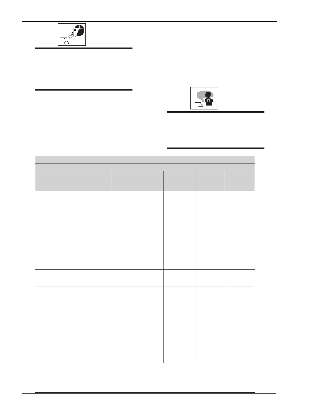
AWS F2.2:2001 (R2010), Adapted with permission of the American Welding Society (AWS), Miami, Florida
Guide for Shade Numbers
Process
Electrode Size in.
(mm)
Arc Current
(Amperes)
Minimum
Protective
Shade
Suggested*
Shade No.
(Comfort)
Shielded Metal Arc Welding
(SMAW)
Less than 3/32 (2.4)
3/32-5/32 (2.4-4.0)
5/32-1/4 (4.0-6.4)
More than 1/4 (6.4)
Less than 60
60-160
160-250
250-550
7
8
10
11
-
10
12
14
Gas Metal Arc Welding (GMAW)
and Flux Cored Arc Welding
(FCAW)
Less than 60
60-160
160-250
250-550
7
10
10
10
-
11
12
14
Gas Tungsten arc Welding
(GTAW)
Less than 50
50-150
150-500
8
8
10
10
12
14
Air Carbon Arc Cutting (CAC-A)
(Light)
(Heavy)
Less than
500
500-1000
10
11
12
14
Plasma Arc Welding (PAW)
Less than 20
20-100
100-400
400-800
6
8
10
11
6 to 8
10
12
14
Plasma Arc Cutting (PAC)
Less than 20
20-40
40-60
60-80
80-300
300-400
400-800
4
5
6
8
8
9
10
4
5
6
8
9
12
14
* As a rule of thumb, start with a shade that is too dark to see the weld zone. Then go to a lighter shade
which gives sufficient view of the weld zone without going below the minimum. In oxyfuel gas welding,
cutting, or brazing where the torch and/or the flux produces a high yellow light, it is desirable to use a
filter lens that absorbs the yellow or sodium line of the visible light spectrum.
SAFETY INSTRUCTIONS FABRICATOR 211i
Manual 0-5157 1-3 SAFETY INSTRUCTIONS AND WARNINGS
1. Keep your head out of the fumes. Do not breathe
the fumes.
2. If inside, ventilate the area and/or use exhaust at the
arc to remove welding fumes and gases.
3. If ventilation is poor, use an approved air-supplied
respirator.
4. Read the Material Safety Data Sheets (MSDSs)
and the manufacturer’s instruction for metals,
consumables, coatings, and cleaners.
5. Work in a confined space only if it is well ventilated,
or while wearing an air-supplied respirator. Shielding
gases used for welding can displace air causing
injury or death. Be sure the breathing air is safe.
6. Do not weld in locations near degreasing, cleaning,
or spraying operations. The heat and rays of the
arc can react with vapors to form highly toxic and
irritating gases.
7. Do not weld on coated metals, such as galvanized,
lead, or cadmium plated steel, unless the coating
is removed from the weld area, the area is well
ventilated, and if necessary, while wearing an air-
supplied respirator. The coatings and any metals
containing these elements can give off toxic fumes
if welded.
WARNING
WELDING can cause fire or explosion.
Sparks and spatter fly off from the welding
arc. The flying sparks and hot metal, weld
spatter, hot workpiece, and hot equipment
can cause fires and burns. Accidental contact
of electrode or welding wire to metal objects
can cause sparks, overheating, or fire.
1. Protect yourself and others from flying sparks and
hot metal.
2. Do not weld where flying sparks can strike flammable
material.
3. Remove all flammables within 35 ft (10.7 m) of the
welding arc. If this is not possible, tightly cover them
with approved covers.
4. Be alert that welding sparks and hot materials from
welding can easily go through small cracks and
openings to adjacent areas.
5. Watch for fire, and keep a fire extinguisher nearby.
6. Be aware that welding on a ceiling, floor, bulkhead,
or partition can cause fire on the hidden side.
7. Do not weld on closed containers such as tanks or
drums.
8. Connect work cable to the work as close to the
welding area as practical to prevent welding current
from travelling long, possibly unknown paths and
causing electric shock and fire hazards.
9. Do not use welder to thaw frozen pipes.
10. Remove stick electrode from holder or cut off
welding wire at contact tip when not in use.
WARNING
FLYING SPARKS AND HOT METAL can cause
injury.
Chipping and grinding cause flying metal. As
welds cool, they can throw off slag.
1. Wear approved face shield or safety goggles. Side
shields recommended.
2. Wear proper body protection to protect skin.
WARNING
CYLINDERS can explode if damaged.
Shielding gas cylinders contain gas under
high pressure. If damaged, a cylinder can
explode. Since gas cylinders are normally
part of the welding process, be sure to treat
them carefully.
1. Protect compressed gas cylinders from excessive
heat, mechanical shocks, and arcs.
2. Install and secure cylinders in an upright position by
chaining them to a stationary support or equipment
cylinder rack to prevent falling or tipping.
3. Keep cylinders away from any welding or other
electrical circuits.
4. Never allow a welding electrode to touch any
cylinder.
5. Use only correct shielding gas cylinders, regulators,
hoses, and fittings designed for the specific
application; maintain them and associated parts in
good condition.
FABRICATOR 211i SAFETY INSTRUCTIONS
SAFETY INSTRUCTIONS AND WARNINGS 1-4 Manual 0-5157
6. Turn face away from valve outlet when opening
cylinder valve.
7. Keep protective cap in place over valve except when
cylinder is in use or connected for use.
8. Read and follow instructions on compressed
gas cylinders, associated equipment, and CGA
publication P-1 listed in Safety Standards.
!
WARNING
Engines can be dangerous.
WARNING
ENGINE EXHAUST GASES can kill.
Engines produce harmful exhaust gases.
1. Use equipment outside in open, well-ventilated
areas.
2. If used in a closed area, vent engine exhaust outside
and away from any building air intakes.
WARNING
ENGINE FUEL can cause fire or explosion.
Engine fuel is highly flammable.
1. Stop engine before checking or adding fuel.
2. Do not add fuel while smoking or if unit is near any
sparks or open flames.
3. Allow engine to cool before fuelling. If possible,
check and add fuel to cold engine before beginning
job.
4. Do not overfill tank — allow room for fuel to expand.
5. Do not spill fuel. If fuel is spilled, clean up before
starting engine.
WARNING
MOVING PARTS can cause injury.
Moving parts, such as fans, rotors, and belts can cut
fingers and hands and catch loose clothing.
1. Keep all doors, panels, covers, and guards
closed and securely in place.
2. Stop engine before installing or connecting unit.
3. Have only qualified people remove guards or
covers for maintenance and troubleshooting as
necessary.
4. To prevent accidental starting during servicing,
disconnect negative (-) battery cable from
battery.
5. Keep hands, hair, loose clothing, and tools away
from moving parts.
6. Reinstall panels or guards and close doors when
servicing is finished and before starting engine.
WARNING
SPARKS can cause BATTERY GASES TO
EXPLODE; BATTERY ACID can burn eyes
and skin.
Batteries contain acid and generate explosive gases.
1. Always wear a face shield when working on a battery.
2. Stop engine before disconnecting or connecting
battery cables.
3. Do not allow tools to cause sparks when working
on a battery.
4. Do not use welder to charge batteries or jump start
vehicles.
5. Observe correct polarity (+ and –) on batteries.
WARNING
STEAM AND PRESSURIZED HOT COOLANT
can burn face, eyes, and skin.
The coolant in the radiator can be very hot
and under pressure.
1. Do not remove radiator cap when engine is hot.
Allow engine to cool.
2. Wear gloves and put a rag over cap area when
removing cap.
3. Allow pressure to escape before completely
removing cap.
SAFETY INSTRUCTIONS FABRICATOR 211i
Manual 0-5157 1-5 SAFETY INSTRUCTIONS AND WARNINGS
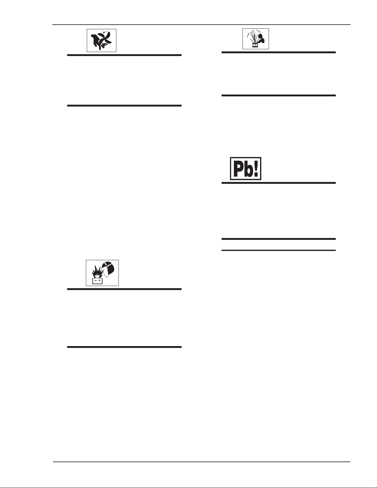
LEAD WARNING
WARNING: This product contains chemicals,
including lead, known to the State of Califor-
nia to cause birth defects and other repro-
ductive harm. Wash hands after handling.
NOTE
Considerations About Welding And The
Effects of Low Frequency Electric and Mag-
netic Fields
The following is a quotation from the General Conclu-
sions Section of the U.S. Congress, Office of Technology
Assessment, Biological Effects of Power Frequency
Electric & Magnetic Fields - Background Paper, OTA-
BP-E-63 (Washington, DC: U.S. Government Printing
Office, May 1989): “...there is now a very large volume
of scientific findings based on experiments at the cel-
lular level and from studies with animals and people
which clearly establish that low frequency magnetic
fields interact with, and produce changes in, biologi-
cal systems. While most of this work is of very high
quality, the results are complex. Current scientific
understanding does not yet allow us to interpret the
evidence in a single coherent framework. Even more
frustrating, it does not yet allow us to draw definite
conclusions about questions of possible risk or to offer
clear science-based advice on strategies to minimize or
avoid potential risks.”
To reduce magnetic fields in the workplace, use the
following procedures.
1. Keep cables close together by twisting or taping
them.
2. Arrange cables to one side and away from the
operator.
3. Do not coil or drape cable around the body.
4. Keep welding Power Source and cables as far
away from body as practical.
ABOUT PACEMAKERS:
The above procedures are among those
also normally recommended for pacemaker
wearers. Consult your doctor for complete
information.
1.02 General Safety Information For
Victor CS Regulator
A Fire Prevention
Welding and cutting operations use fire or combustion
as a basic tool. The process is very useful when properly
controlled. However, it can be extremely destructive
if not performed cor rectly in the proper environment.
1. The work area must have a fireproof floor.
2. Work benches or tables used during welding or
cutting operations must have fireproof tops.
3. Use heat resistant shields or other approved mate-
rial to protect nearby walls or unprotected flooring
from sparks and hot metal.
4. Keep an approved fire extinguisher of the proper
size and type in the work area. Inspect it regu-
larly to ensure that it is in proper working order.
Know how to use the fire extin guisher.
5. Move combustible materials away from the work
site. If you can not move them, protect them
with fireproof covers.
!
WARNING
NEVER perform welding, heating, or cut-
ting operations on a container that has held
toxic, combustible or flammable liq uids, or
vapors. NEVER perform welding, heating,
or cutting operations in an area containing
combustible vapors, flam mable liquids, or
explosive dust.
B Housekeeping
!
WARNING
NEVER allow oxygen to contact grease, oil, or
other flam mable substances. Although oxy-
gen by itself will not burn, these substances
become highly explosive. They can ignite
and burn violently in the presence of oxygen.
Keep ALL apparatus clean and free of grease, oil and
other flammable substances.
FABRICATOR 211i SAFETY INSTRUCTIONS
SAFETY INSTRUCTIONS AND WARNINGS 1-6 Manual 0-5157
C Ventilation
!
WARNING
Ade quately ventilate welding, heating, and
cutting work areas to prevent accumula-
tion of explosive or toxic concen trations
of gases. Certain combinations of metals,
coatings, and gases generate toxic fumes.
Use respiratory protection equipment in
these circumstances. When welding/brazing,
read and understand the Material Safety Data
Sheet for the welding/brazing alloy.
D Personal Protection
Gas flames produce infrared radiation which may have
a harm ful effect on the skin and especially on the eyes.
Select goggles or a mask with tempered lenses, shaded
4 or darker, to protect your eyes from injury and provide
good visibility of the work.
Always wear protective gloves and flame-resistant clothing
to protect skin and clothing from sparks and slag. Keep
collars, sleeves, and pockets buttoned. DO NOT roll up
sleeves or cuff pants.
When working in a non-welding or cutting environment,
always wear suitable eye protection or face shield.
!
WARNING
Practice the following safety and operation
precautions EVERY TIME you use pressure
regulation equipment. Deviation from the
following safety and operation instructions
can result in fire, explosion, damage to
equipment, or injury to the operator.
E Compressed Gas Cylinders
The Department of Transportation (DOT) approves the
design and manufacture of cylinders that contain gases
used for welding or cutting operations.
1. Place the cylinder (Figure 1-1) where you will
use it. Keep the cylinder in a vertical position.
Secure it to a cart, wall, work bench, post, etc.
Art # A-12127
Figure 1-1: Gas Cylinders
!
WARNING
Cylinders are highly pressurized. Handle
with care. Serious accidents can result from
improper handling or mis use of compressed
gas cylinders DO NOT drop the cylinder,
knock it over, or expose it to excessive heat,
flames or sparks. DO NOT strike it against
other cylinders. Contact your gas supplier
or refer to CGA P-1 “Safe Handling of Com-
pressed Gases in Containers” publication.
NOTE
CGA P-1 publication is available by writing
the Compressed Gas Association, 4221
Walney Road, 5th Floor, Chantilly,VA 20151-
2923
2. Place the valve protection cap on the cylinder
whenever mov ing it, placing it in storage, or not
using it. Never drag or roll cylinders in any way.
Use a suitable hand truck to move cylin ders.
3. Store empty cylinders away from full cylinders.
Mark them “EMPTY” and close the cylinder valve.
4. NEVER use compressed gas cylinders without
a pressure reducing regulator attached to the
cylinder valve.
5. Inspect the cylinder valve for oil, grease, and
damaged parts.
!
WARNING
DO NOT use the cylinder if you find oil,
grease or damaged parts. Inform your gas
supplier of this condition immediately.
6. Momentarily open and close (called “cracking”)
the cylinder valve to dislodge any dust or dirt that
may be present in the valve.
CAUTION
Open the cylinder valve slightly. If you open
the valve too much, the cylinder could tip
over. When cracking the cylinder valve, DO
NOT stand directly in front of the cylinder
valve. Always perform cracking in a well
ventilated area. If an acetylene cylinder
sprays a mist when cracked, let it stand for
15 minutes. Then, try to crack the cylinder
valve again. If this problem persists, contact
your gas supplier.

SAFETY INSTRUCTIONS FABRICATOR 211i
Manual 0-5157 1-7 SAFETY INSTRUCTIONS AND WARNINGS
1.03 Principal Safety Standards
Safety in Welding and Cutting, ANSI Standard Z49.1,
from American Welding Society, 550 N.W. LeJeune Rd.,
Miami, FL 33126.
Safety and Health Standards, OSHA 29 CFR 1910,
from Superintendent of Documents, U.S. Government
Printing Office, Washington, D.C. 20402.
Recommended Safe Practices for the Preparation for
Welding and Cutting of Containers That Have Held
Hazardous Substances, American Welding Society
Standard AWS F4.1, from American Welding Society,
550 N.W. LeJeune Rd., Miami, FL 33126.
National Electrical Code, NFPA Standard 70, from
National Fire Protection Association, Batterymarch Park,
Quincy, MA 02269.
Safe Handling of Compressed Gases in Cylinders, CGA
Pamphlet P-1, from Compressed Gas Association,
1235 Jefferson Davis Highway, Suite 501, Arlington,
VA 22202.
Code for Safety in Welding and Cutting, CSA Standard
W117.2, from Canadian Standards Association,
Standards Sales, 178 Rexdale Boulevard, Rexdale,
Ontario, Canada M9W 1R3.
Safe Practices for Occupation and Educational Eye and
Face Protection, ANSI Standard Z87.1, from American
National Standards Institute, 1430 Broadway, New York,
NY 10018.
Cutting and Welding Processes, NFPA Standard 51B,
from National Fire Protection Association, Batterymarch
Park, Quincy, MA 02269.
FABRICATOR 211i SAFETY INSTRUCTIONS
SAFETY INSTRUCTIONS AND WARNINGS 1-8 Manual 0-5157
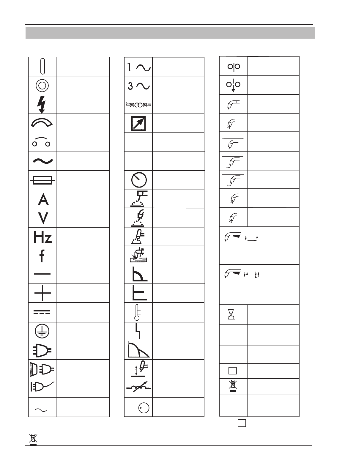
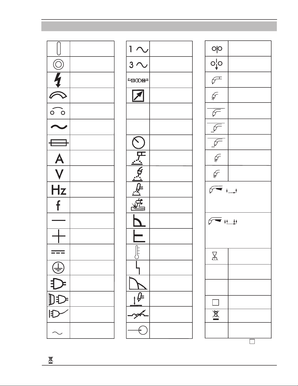
1.04 Symbol Chart
Note that only some of these symbols will appear on your model.
Gas Tungsten Arc
Welding (GTAW)
Air Carbon Arc
Cutting (CAC-A)
Constant Current
Constant Voltage
Or Constant Potential
High Temperature
Fault Indication
Arc Force
Touch Start (GTAW)
Variable Inductance
Voltage Input
Single Phase
Three Phase
Three Phase Static
Frequency Converter-
Transformer-Rectifier
Dangerous Voltage
Off
On
Panel/Local
Shielded Metal
Arc Welding (SMAW)
Gas Metal Arc
Welding (GMAW)
Increase/Decrease
Circuit Breaker
AC Auxiliary Power
Remote
Duty Cycle
Percentage
Amperage
Voltage
Hertz (cycles/sec)
Frequency
Negative
Positive
Direct Current (DC)
Protective Earth
(Ground)
Line
Line Connection
Auxiliary Power
Receptacle Rating-
Auxiliary Power
Art # A-04130_AB
115V 15A
t
t1
t2
%
X
IPM
MPM
t
V
Fuse
Wire Feed Function
Wire Feed Towards
Workpiece With
Output Voltage Off.
Preflow Time
Postflow Time
Spot Time
Spot Weld Mode
Continuous Weld
Mode
Press to initiate wirefeed and
welding, release to stop.
Purging Of Gas
Inches Per Minute
Meters Per Minute
Welding Gun
Burnback Time
Press and hold for preflow, release
to start arc. Press to stop arc, and
hold for preflow.
4 Step Trigger
Operation
2 Step Trigger
Operation
S
See Note
See Note
S
Note: For environments with increased hazard of electrical shock, Power Supplier bearing the mark conform to EN50192
when used in conjunction with hand torches with exposed tips, if equipped with properly installed standoff guides.
Cannot be disposed with household garbage.
SAFETY INSTRUCTIONS FABRICATOR 211i
Manual 0-5157 1-9 SAFETY INSTRUCTIONS AND WARNINGS
1.05 Precautions De Securite En Soudage A L’arc
!
MISE EN GARDE
LE SOUDAGE A L’ARC EST DANGEREUX
PROTEGEZ-VOUS, AINSI QUE LES AUTRES, CONTRE LES BLESSURES GRAVES POSSIBLES OU LA MORT. NE
LAISSEZ PAS LES ENFANTS S’APPROCHER, NI LES PORTEURS DE STIMULATEUR CARDIAQUE (A MOINS QU’ILS
N’AIENT CONSULTE UN MEDECIN). CONSERVEZ CES INSTRUCTIONS. LISEZ LE MANUEL D’OPERATION OU LES
INSTRUCTIONS AVANT D’INSTALLER, UTILISER OU ENTRETENIR CET EQUIPEMENT.
Les produits et procédés de soudage peuvent sauser des blessures graves ou la mort, de même que des dommages
au reste du matériel et à la propriété, si l’utilisateur n’adhère pas strictement à toutes les règles de sécurité et ne
prend pas les précautions nécessaires.
En soudage et coupage, des pratiques sécuritaires se sont développées suite à l’expérience passée. Ces pratiques
doivent être apprises par étude ou entraînement avant d’utiliser l’equipement. Toute personne n’ayant pas suivi
un entraînement intensif en soudage et coupage ne devrait pas tenter de souder. Certaines pratiques concernent
les équipements raccordés aux lignes d’alimentation alors que d’autres s’adressent aux groupes électrogènes.
La norme Z49.1 de l’American National Standard, intitulée “SAFETY IN WELDING AND CUTTING” présente les
pratiques sécuritaires à suivre. Ce document ainsi que d’autres guides que vous devriez connaître avant d’utiliser
cet équipement sont présentés à la fin de ces instructions de sécurité.
SEULES DES PERSONNES QUALIFIEES DOIVENT FAIRE DES TRAVAUX D’INSTALLATION, DE REPARATION,
D’ENTRETIEN ET D’ESSAI.
1.06 Dangers relatifs au soudage à
l’arc
AVERTISSEMENT
L’ELECTROCUTION PEUT ETRE MORTELLE.
Une décharge électrique peut tuer ou
brûler gravement. L’électrode et le circuit
de soudage sont sous tension dès la mise
en circuit. Le circuit d’alimentation et les
circuits internes de l’équipement sont aussi
sous tension dès la mise en marche. En
soudage automatique ou semi-automatique
avec fil, ce dernier, le rouleau ou la bobine
de fil, le logement des galets d’entrainement
et toutes les pièces métalliques en contact
avec le fil de soudage sont sous tension.
Un équipement inadéquatement installé ou
inadéquatement mis à la terre est dangereux.
1. Ne touchez pas à des pièces sous tension.
2. Portez des gants et des vêtements isolants, secs et
non troués.
3 Isolez-vous de la pièce à souder et de la mise à la
terre au moyen de tapis isolants ou autres.
4. Déconnectez la prise d’alimentation de l’équipement
ou arrêtez le moteur avant de l’installer ou d’en faire
l’entretien. Bloquez le commutateur en circuit ouvert
ou enlevez les fusibles de l’alimentation afin d’éviter
une mise en marche accidentelle.
5. Veuillez à installer cet équipement et à le mettre à
la terre selon le manuel d’utilisation et les codes
nationaux, provinciaux et locaux applicables.
6. Arrêtez tout équipement après usage. Coupez l’ali-
mentation de l’équipement s’il est hors d’usage ou
inutilisé.
7. N’utilisez que des porte-électrodes bien isolés. Ne
jamais plonger les porte-électrodes dans l’eau pour
les refroidir. Ne jamais les laisser traîner par terre ou
sur les pièces à souder. Ne touchez pas aux porte-
électrodes raccordés à deux sources de courant en
même temps. Ne jamais toucher quelqu’un d’autre
avec l’électrode ou le porte-électrode.
8. N’utilisez pas de câbles électriques usés, endom-
magés, mal épissés ou de section trop petite.
9. N’enroulez pas de câbles électriques autour de votre
corps.
10. N’utilisez qu’une bonne prise de masse pour la mise
à la terre de la pièce à souder.
FABRICATOR 211i SAFETY INSTRUCTIONS
SAFETY INSTRUCTIONS AND WARNINGS 1-10 Manual 0-5157
11. Ne touchez pas à l’électrode lorsqu’en contact avec
le circuit de soudage (terre).
12. N’utilisez que des équipements en bon état. Réparez
ou remplacez aussitôt les pièces endommagées.
13. Dans des espaces confinés ou mouillés, n’utilisez
pas de source de courant alternatif, à moins qu’il
soit muni d’un réducteur de tension. Utilisez plutôt
une source de courant continu.
14. Portez un harnais de sécurité si vous travaillez en
hauteur.
15. Fermez solidement tous les panneaux et les capots.
AVERTISSEMENT
LE RAYONNEMENT DE L’ARC PEUT BRÛLER
LES YEUX ET LA PEAU; LE BRUIT PEUT
ENDOMMAGER L’OUIE.
L’arc de soudage produit une chaleur et des
rayons ultraviolets intenses, susceptibles de
brûler les yeux et la peau. Le bruit causé par
certains procédés peut endommager l’ouïe.
1. Portez une casque de soudeur avec filtre oculaire
de nuance appropriée (consultez la norme ANSI Z49
indiquée ci-après) pour vous protéger le visage et
les yeux lorsque vous soudez ou que vous observez
l’exécution d’une soudure.
AWS F2.2 : 2001 (R2010), Modifié avec l’accord de l’American Welding Society (AWS), Miami, Florida
Guide de teinte des lentilles
Procédé
Taille de l’électrode
enmm (po)
Courant
d’arc
(ampères)
Gamme
d’intensité
minimum
Numéro de teinte
recommandée*
(Confort)
Soudage à l’arc avec
électrode enrobée (procédé
SMAW)
Moins de 2,4 (3/32)
3/32-5/32 (2,4-4,0)
5/32-1/4 (4,0-6,4)
Plus de 1/4 (6,4)
Moins de 60
60-160
160-250
250-550
7
8
10
11
-
10
12
14
Soudage à l’arc sous gaz
avec fil plein (procédé
GMAW) et soudage avec fil
fourré (procédé FCAW)
Moins de 60
60-160
160-250
250-550
7
10
10
10
-
11
12
14
Soudage à l’électrode
réfractaire (procédé GTAW)
Moins de 50
50-150
150-500
8
8
10
10
12
14
Coupage à l’arc avec
électrode de carbone et jet
d’air (procédé AAC)
(Clair)
(Sombre)
Moins de
500 500-
1000
10
11
12
14
Soudage à l’arc au plasma
(procédé PAW)
Moins de 20
20-100
100-400
400-800
6
8
10
11
6 à 8
10
12
14
Coupage plasma (procédé
PAC)
Moins de 20
20-40
40-60
60-80
80-300
300-400
400-800
4
5
6
8
8
9
10
4
5
6
8
9
12
14
* En règle générale, commencer avec une teinte plus foncée pour voir la zone de soudage. Réduire ensuite
progressivement vers la teinte qui permet de voir la zone de soudage sans dépasser le minimum. Lors
dusoudage, du coupage ou du brasage au gaz oxygéné, la torche ou le fondant produit une puissante
lumière jaune; il est préférable d’utiliser un filtre qui absorbe cette lumière jaune ou le sodium du spectre
de la lumière visible.
Tableau 1-1
SAFETY INSTRUCTIONS FABRICATOR 211i
Manual 0-5157 1-11 SAFETY INSTRUCTIONS AND WARNINGS
AVERTISSEMENT
LE SOUDAGE PEUT CAUSER UN INCENDIE
OU UNE EXPLOSION
L’arc produit des étincellies et des pro-
jections. Les particules volantes, le métal
chaud, les projections de soudure et l’équi-
pement surchauffé peuvent causer un incen-
die et des brûlures. Le contact accidentel de
l’électrode ou du fil-électrode avec un objet
métallique peut provoquer des étincelles, un
échauffement ou un incendie.
1. Protégez-vous, ainsi que les autres, contre les étin-
celles et du métal chaud.
2. Ne soudez pas dans un endroit où des particules
volantes ou des projections peuvent atteindre des
matériaux inflammables.
3. Enlevez toutes matières inflammables dans un rayon
de 10, 7 mètres autour de l’arc, ou couvrez-les soi-
gneusement avec des bâches approuvées.
4. Méfiez-vous des projections brulantes de soudage
susceptibles de pénétrer dans des aires adjacentes
par de petites ouvertures ou fissures.
5. Méfiez-vous des incendies et gardez un extincteur
à portée de la main.
6. N’oubliez pas qu’une soudure réalisée sur un pla-
fond, un plancher, une cloison ou une paroi peut
enflammer l’autre côté.
7. Ne soudez pas un récipient fermé, tel un réservoir
ou un baril.
8. Connectez le câble de soudage le plus près possible
de la zone de soudage pour empêcher le courant de
suivre un long parcours inconnu, et prévenir ainsi
les risques d’électrocution et d’incendie.
9. Ne dégelez pas les tuyaux avec un source de courant.
10. Otez l’électrode du porte-électrode ou coupez le fil
au tube-contact lorsqu’inutilisé après le soudage.
11. Portez des vêtements protecteurs non huileux, tels
des gants en cuir, une chemise épaisse, un pantalon
revers, des bottines de sécurité et un casque.
2. Portez des lunettes de sécurité approuvées. Des
écrans latéraux sont recommandés.
3. Entourez l’aire de soudage de rideaux ou de cloisons
pour protéger les autres des coups d’arc ou de
l’éblouissement; avertissez les observateurs de ne
pas regarder l’arc.
4. Portez des vêtements en matériaux ignifuges et dura-
bles (laine et cuir) et des chaussures de sécurité.
5. Portez un casque antibruit ou des bouchons d’oreille
approuvés lorsque le niveau de bruit est élevé.
AVERTISSEMENT
LES VAPEURS ET LES FUMEES SONT
DANGEREUSES POUR LA SANTE.
Le soudage dégage des vapeurs et des
fumées dangereuses à respirer.
1. Eloignez la tête des fumées pour éviter de les respi-
rer.
2. A l’intérieur, assurez-vous que l’aire de soudage est
bien ventilée ou que les fumées et les vapeurs sont
aspirées à l’arc.
3. Si la ventilation est inadequate, portez un respirateur
à adduction d’air approuvé.
4. Lisez les fiches signalétiques et les consignes
du fabricant relatives aux métaux, aux produits
consummables, aux revêtements et aux produits
nettoyants.
5. Ne travaillez dans un espace confiné que s’il est bien
ventilé; sinon, portez un respirateur à adduction d’air.
Les gaz protecteurs de soudage peuvent déplacer
l’oxygène de l’air et ainsi causer des malaises ou la
mort. Assurez-vous que l’air est propre à la respi-
ration.
6. Ne soudez pas à proximité d’opérations de dégrais-
sage, de nettoyage ou de pulvérisation. La chaleur et
les rayons de l’arc peuvent réagir avec des vapeurs
et former des gaz hautement toxiques et irritants.
7. Ne soudez des tôles galvanisées ou plaquées au
plomb ou au cadmium que si les zones à souder ont
été grattées à fond, que si l’espace est bien ventilé;
si nécessaire portez un respirateur à adduction d’air.
Car ces revêtements et tout métal qui contient ces
éléments peuvent dégager des fumées toxiques au
moment du soudage.
FABRICATOR 211i SAFETY INSTRUCTIONS
SAFETY INSTRUCTIONS AND WARNINGS 1-12 Manual 0-5157
AVERTISSEMENT
LES ETINCELLES ET LES PROJECTIONS
BRULANTES PEUVENT CAUSER DES
BLESSURES.
Le piquage et le meulage produisent des
particules métalliques volantes. En refroi-
dissant, la soudure peut projeter du éclats
de laitier.
1. Portez un écran facial ou des lunettes protec-
trices approuvées. Des écrans latéraux sont
recommandés.
2. Portez des vêtements appropriés pour protéger
la peau.
AVERTISSEMENT
LES BOUTEILLES ENDOMMAGEES PEU-
VENT EXPLOSER
Les bouteilles contiennent des gaz protec-
teurs sous haute pression. Des bouteilles
endommagées peuvent exploser. Comme
les bouteilles font normalement partie du
procédé de soudage, traitez-les avec soin.
1. Protégez les bouteilles de gaz comprimé contre les
sources de chaleur intense, les chocs et les arcs de
soudage.
2. Enchainez verticalement les bouteilles à un support
ou à un cadre fixe pour les empêcher de tomber ou
d’être renversées.
3. Eloignez les bouteilles de tout circuit électrique ou
de tout soudage.
4. Empêchez tout contact entre une bouteille et une
électrode de soudage.
5. N’utilisez que des bouteilles de gaz protecteur, des
détendeurs, des boyauxs et des raccords conçus
pour chaque application spécifique; ces équipe-
ments et les pièces connexes doivent être maintenus
en bon état.
6. Ne placez pas le visage face à l’ouverture du robinet
de la bouteille lors de son ouverture.
7. Laissez en place le chapeau de bouteille sauf si en
utilisation ou lorsque raccordé pour utilisation.
8. Lisez et respectez les consignes relatives aux
bouteilles de gaz comprimé et aux équipements
connexes, ainsi que la publication P-1 de la CGA,
identifiée dans la liste de documents ci-dessous.
AVERTISSEMENT
LES MOTEURS PEUVENT ETRE DANGE-
REUX
LES GAZ D’ECHAPPEMENT DES MOTEURS
PEUVENT ETRE MORTELS.
Les moteurs produisent des gaz d’échappement nocifs.
1. Utilisez l’équipement à l’extérieur dans des aires
ouvertes et bien ventilées.
2. Si vous utilisez ces équipements dans un endroit
confiné, les fumées d’échappement doivent être
envoyées à l’extérieur, loin des prises d’air du bâti-
ment.
AVERTISSEMENT
LE CARBURANT PEUR CAUSER UN INCEN-
DIE OU UNE EXPLOSION.
Le carburant est hautement inflammable.
1. Arrêtez le moteur avant de vérifier le niveau e car-
burant ou de faire le plein.
2. Ne faites pas le plein en fumant ou proche d’une
source d’étincelles ou d’une flamme nue.
3. Si c’est possible, laissez le moteur refroidir avant de
faire le plein de carburant ou d’en vérifier le niveau
au début du soudage.
4. Ne faites pas le plein de carburant à ras bord: pré-
voyez de l’espace pour son expansion.
5. Faites attention de ne pas renverser de carburant.
Nettoyez tout carburant renversé avant de faire
démarrer le moteur.
SAFETY INSTRUCTIONS FABRICATOR 211i
Manual 0-5157 1-13 SAFETY INSTRUCTIONS AND WARNINGS
AVERTISSEMENT
DES PIECES EN MOUVEMENT PEUVENT
CAUSER DES BLESSURES.
Des pièces en mouvement, tels des ventila-
teurs, des rotors et des courroies peuvent
couper doigts et mains, ou accrocher des
vêtements amples.
1. Assurez-vous que les portes, les panneaux, les
capots et les protecteurs soient bien fermés.
2. Avant d’installer ou de connecter un système, arrêtez
le moteur.
3. Seules des personnes qualifiées doivent démonter
des protecteurs ou des capots pour faire l’entretien
ou le dépannage nécessaire.
4. Pour empêcher un démarrage accidentel pendant
l’entretien, débranchez le câble d’accumulateur à la
borne négative.
5. N’approchez pas les mains ou les cheveux de pièces
en mouvement; elles peuvent aussi accrocher des
vêtements amples et des outils.
6. Réinstallez les capots ou les protecteurs et fermez
les portes après des travaux d’entretien et avant de
faire démarrer le moteur.
AVERTISSEMENT
DES ETINCELLES PEUVENT FAIRE EXPLO-
SER UN ACCUMULATEUR; L’ELECTROLYTE
D’UN ACCUMU-LATEUR PEUT BRULER LA
PEAU ET LES YEUX.
Les accumulateurs contiennent de l’élec-
trolyte acide et dégagent des vapeurs
explosives.
1. Portez toujours un écran facial en travaillant sur un
accumu-lateur.
2. Arrêtez le moteur avant de connecter ou de décon-
necter des câbles d’accumulateur.
3. N’utilisez que des outils anti-étincelles pour travailler
sur un accumulateur.
4. N’utilisez pas une source de courant de soudage
pour charger un accumulateur ou survolter momen-
tanément un véhicule.
5. Utilisez la polarité correcte (+ et –) de l’accumulateur.
AVERTISSEMENT
LA VAPEUR ET LE LIQUIDE DE REFROI-
DISSEMENT BRULANT SOUS PRESSION
PEUVENT BRULER LA PEAU ET LES YEUX.
Le liquide de refroidissement d’un radiateur
peut être brûlant et sous pression.
1. N’ôtez pas le bouchon de radiateur tant que le moteur
n’est pas refroidi.
2. Mettez des gants et posez un torchon sur le bouchon
pour l’ôter.
3. Laissez la pression s’échapper avant d’ôter complè-
tement le bouchon.
PLOMB AVERTISSEMENT
Ce produit contient des produits chimiques,
comme le plomb, ou engendre des produits
chimiques, reconnus par l’état de Californie
comme pouvant être à l’origine de malfor-
mations fœtales ou d’autres problèmes de
reproduction. Il faut se laver les mains
après toute manipulation.
REMARQUE
Facteurs relatifs au soudage et aux effets
des champs magnétiques et électriques de
basse fréquence
Voici une citation tirée du chapitre des conclusions
générales du document de base de l’Office of Technology
Assessment (bureau des évaluations technologiques)
del’U.S. Congress, « Biological Effects of Power
Frequency Electric & Magnetic Fields », OTA-BP-E-63
(Washington, DC : U.S. Government Printing Office,
mai 1989) : « ... il existe de nos jours, un nombre
très élevé de travaux scientifiques qui rapportent les
résultats d’expériences menées au niveau cellulaire et
d’études auprès d’homme et d’animaux qui établissent
nettement le rapport entre les champs magnétiques de
basse fréquence et les systèmes biologiques, soit par des
interactions ou des modifications. Quoique la plupart de
ces travaux soient de très bonne qualité, les résultats sont
complexes. Àla lumière des connaissances scientifiques
actuelles, il nous est encore impossible d’interpréter les
évidences en un seul cadre de référence cohérent. La
situation est toutefois très contrariante. En effet, il nous
est aussi impossible de tirer des conclusions définitives
quant aux risques éventuels ou de proposer des stratégies
fondées sur des faits scientifiques visant à atténuer ou
éviter des risques potentiels ».
FABRICATOR 211i SAFETY INSTRUCTIONS
SAFETY INSTRUCTIONS AND WARNINGS 1-14 Manual 0-5157
Pour atténuer les champs magnétiques sur les lieux
detravail, respectez les procédures qui suivent :
1. Maintenez les câbles l’un près de l’autre en les
entrelaçant ou les reliant ensemble au ruban.
2. Acheminez les câbles à un côté du soudeur, le
plus loin possible.
3. N’enroulez pas de câble autour du corps.
4. Maintenez le bloc d’alimentation du poste
desoudage et les câbles aussi loin que possible
du corps.
STIMULATEURS CARDIAQUES :
Les procédures décrites ci-dessus sont
habituellement celles recommandées pour
les porteurs de stimulateurs cardiaques.
Pour de plus amples renseignements,
consulter unmédecin.
1.07 Informations Générales de
Sécurité
A Prévention D’incendie
Les opérations de soudage utilisent le feu ou la combustion
comme outil de base. Ce processus est très utile quand il
est cor rectement contrôlé.
1. La zone doit comporter un sol ignifugé.
2. Les établis ou tables utilisés pendant les opéra-
tions de soudage doivent avoir un revêtement
ignifuge.
3. Utilisez des écrans résistants à la chaleur ou en
matériau approuvé pour protéger les cloisons
proches ou le sol vul nérable des étincelles et du
métal chaud.
4. Gardez un extincteur approuvé du bon type et de
la bonne taille dans la zone de travail. Inspectez-le
régulièrement pour vous assurer qu’il est en état de
fonctionner. Apprenez à vous en servir.
5. Enlevez tous les matériaux combustibles de la
zone de travail. Si vous ne pouvez pas les enlever,
protégez-les avec une cou vre ignifuge.
!
AVERTISSEMENT
N’effectuez JAMAIS d’opérations de soudage
sur un récipient qui a contenu des liquides ou
vapeurs toxiques, combustibles ou inflamma-
bles. N’effectuez
JAMAIS d’opérations de sou-
dage dans une zone contenant des vapeurs
combustibles, des liquides inflammables ou
des poussières explosives.
B Entretien des Locaux
!
AVERTISSEMENT
Ne laissez jamais l’oxygène en contact avec
la graisse, l’huile ou d’autres substances
inflammables. Bien que l’oxygène elle même
ne brûle pas, ces substances peuvent deve-
nir extrême ment explosives. Elles peuvent
prendre feu et brûler violem ment en pré-
sence d’oxygène.
Gardez TOUS les appareils propres et exempts de graisse,
huile ou autres substances inflammables.
C Aération
!
AVERTISSEMENT
Ventilez les zones de soudage, chauffage et
découpage de façon adéquate pour éviter
l’accumulation de gaz explosifs ou toxiques.
Certaines combinaisons de métaux, revête-
ments et gaz génèrent des fumées toxiques:
Utilisez un équipement de protection res-
piratoire dans ces circonstances. Si vous
soudez ou brasez, lisez et assimilez la fiche
technique de sécurité de matériau relative à
l’alliage de soudage/brasage.
D Protection Personnelle
Les flammes de gaz produisent une radiation infrarouge
qui peut avoir un effet néfaste sur la peau, et particu-
lièrement sur les yeux. Choisissez des lunettes ou un
masque avec des verres trempés assombris au niveau 4
ou plus sombre, pour protéger vos yeux des dommages
et garder une bonne visibilité sur le travail.
Portez en permanence des gants de protection et des
vête ments ignifuges pour la protection de la peau et des
vêtements contre les étincelles et le laitier. Gardez col,
manches et poches boutonnés. Il ne faut pas remonter
vos manches ou les pantalons à revers.
Quand vous travaillez dans un environnement non
dédié au soudage ou découpage, portez toujours une
protection des yeux appropriées ou un masque facial.
SAFETY INSTRUCTIONS FABRICATOR 211i
Manual 0-5157 1-15 SAFETY INSTRUCTIONS AND WARNINGS
!
AVERTISSEMENT
Mettez en pratique les procédures de sé-
curité et de mode opératoire suivantes à
chaque fois que vous utilisez cet appareil
de régulation de pression. Si vous déviez de
ces procédures, cela peut entraîner incendie,
explosion, dégâts matériels et/ou blessures
corporelles pour l’opérateur.
E Bouteilles de Gaz Comprimé
Le Département des Transports américain (DOT)
approuve la conception et la fabrication des bouteilles
qui contiennent les gaz utilisés pour les opérations de
soudage ou de découpage.
1. Placez la bouteille (Le schéma 1) là où elle sera uti-
lisée. Gardez-la en position verticale. Fixez-la sur un
chariot une cloison, un établi, etc.
Art # A-12127
Le schéma 1-1: Cylindres de gaz
!
AVERTISSEMENT
Les bouteilles sont sous haute pression. Manipu-
lez-les avec précautions. Des accidents sérieux
peuvent résulter d’une mauvaise manutention
ou d’un mauvais emploi des bouteilles de gaz
comprimé. NE faites PAS tomber la bouteille,
ne la cognez pas, ne l’exposez pas à une chaleur
excessive, aux flammes ou étincelles. NE la cognez
PAS contre d’autres bouteilles. Contactez votre
fournisseur de gaz ou reportez vous à la publication
CGA P-1 “Manipulation sécurisée des gaz compri-
més en conteneur” pour plus d’informations sur
l’utilisation et la manutention des bouteilles.
AVIS
Ce document CGA p. t peut être obtenu en
écrivant à “Compressed Gas Association”,
4221 Walney Roed, 5th Floor. Chantilly, VA
20151.2923, USA.
2. Placez le bouchon de protection de vanne sur
la bouteille à chaque fois que vous la déplacez
ou ne l’utilisez pas. Ne faites jamais glisser ou
rouler d’aucune manière les bouteilles. Utilisez
un diable approprié pour les déplacer.
3. Entreposez les bouteilles vides à l’écart des bou-
teilles pleines. Marquez-les “VIDE” et refermez
leur vanne.
4. N’utilisez JAMAIS des bouteilles de gaz com-
primé sans un régulateur de pression en série
sur la vanne de bouteille.
5. Inspectez la vanne de bouteille pour y détec-
ter de l’huile ou de la graisse, ou dès pièces
endommagées.
!
AVERTISSEMENT
N’UTILISEZ PAS la bouteille si vous trou-
vez de l’huile, de la graisse ou des pièces
endommagées. Informez immédiate ment
votre fournisseur de’ gaz de cet état.
6. Ouvrez et fermez momentanément la vanne de
la bouteille, délogeant ainsi d’éventu lIes pous-
sières ou saletés. qui pour raient être présentes
dans la vanne.
MISE EN GARDE
Ouvrez la vanne de bouteille légèrement.
Si vous l’ouvrez trop en grand, la bouteille
pourrait se renverser. Quand vous ouvrez/
fermez rapidement la vanne de bouteille, ne
vous tenez pas directement devant. Opérez
toujours cette opération dans une zone bien
ventilée. Si une bouteille d’acétylène crache
un brouillard, laissez reposer pendant 15
minutes. Essayez de nouveau la vanne. Si
le problème persiste, con tactez votre four-
nisseur de gaz.

FABRICATOR 211i SAFETY INSTRUCTIONS
SAFETY INSTRUCTIONS AND WARNINGS 1-16 Manual 0-5157
1.08 Principales Normes De Securite
Safety in Welding and Cutting, norme ANSI Z49.1,
American Welding Society, 550 N.W. LeJeune Rd.,
Miami, FL 33128.
Safety and Health Standards, OSHA 29 CFR 1910, Supe-
rintendent of Documents, U.S. Government Printing
Office, Washington, D.C. 20402.
Recommended Safe Practices for the Preparation for
Welding and Cutting of Containers That Have Held
Hazardous Substances, norme AWS F4.1, American
Welding Society, 550 N.W. LeJeune Rd., Miami, FL
33128.
National Electrical Code, norme 70 NFPA, National Fire
Protection Association, Batterymarch Park, Quincy,
MA 02269.
Safe Handling of Compressed Gases in Cylinders, docu-
ment P-1, Compressed Gas Association, 1235 Jefferson
Davis Highway, Suite 501, Arlington, VA 22202.
Code for Safety in Welding and Cutting, norme CSA
W117.2 Association canadienne de normalisation, Stan-
dards Sales, 276 Rexdale Boulevard, Rexdale, Ontario,
Canada M9W 1R3.
Safe Practices for Occupation and Educational Eye and
Face Protection, norme ANSI Z87.1, American National
Standards Institute, 1430 Broadway, New York, NY
10018.
Cutting and Welding Processes, norme 51B NFPA,
National Fire Protection Association, Batterymarch Park,
Quincy, MA 02269.
SAFETY INSTRUCTIONS FABRICATOR 211i
Manual 0-5157 1-17 SAFETY INSTRUCTIONS AND WARNINGS
Soudage á L’arc Avec
Electrode Non Fusible
(GTAW)
Decoupe Arc Carbone
(CAC-A)
Courant Constant
Tension Constante
Ou Potentiel Constant
Haute Température
Force d’Arc
Amorçage de L’arc au
Contact (GTAW)
Inductance Variable
Tension
Mono Phasé
Trois Phasé
Tri-Phase Statique
Fréquence Convertisseur
Transformateur-Redresseur
Tension dangereuse
Hors Tension
SousTension
Panneau/Local
Soudage Arc Electrique
Avec Electrode Enrobé
(SMAW)
Soudage á L’arc Avec
Fil Electrodes Fusible
(GMAW)
Augmentez/Diminuer
Disjoncteur
Source AC Auxiliaire
Distant
Facteur de Marche
Pourcentage
Intensité de Courant
Tension
Hertz (cycles/sec)
Fréquence
Négatif
Positif
Courant Continue (DC)
Terre de Protection
Ligne
Connexion de la Ligne
Source Auxiliaire
Classement de Prise-
Source Auxiliaire
Art # A-07639F_AC
115V 15A
t
t1
t2
%
X
IPM
MPM
t
Fusible
Déroulement du Fil
Alimentation du Fil Vers
la Pièce de Fabrication
Hors Tension
Durée de Pré-Dèbit
Durée de Post-Dèbit
Duréc du Pulse
Soudure Par Point
Appuyez pour démarrer
l’alimentation du fils et la soudure,
le relâcher pour arrêter.
Purge Du Gaz
Mode Continu de
Soudure
Pouces Par Minute
Mètres Par Minute
Torche de Soudage
Probléme de Terre
Maintenez appuyez pour pré-dèbit,
relailez pour initier l’arc. Appuyez
pour arrêter l’arc, et mainteuir pour
pré-dèbit.
Détente à 4-Temps
Détente à 2-Temps
V
S
S
Voir Note
Voir Note
Avis : Pour les environnements avec des risques de choc électrique, le fournisseur d’énergie portant la marque conforme
à EN50192 lorsqu’utilisé en conjonction avec des lampes de poche avec des conseils exposés, si équipés avec des guide à
l’hauteur de buse correctement installé.
Ne pas déposer avec les déchets ménagers.
Indication d’erreur
1.09 Graphique de Symbole
Seulement certains de ces symboles apparaîtront sur votre modèle.

FABRICATOR 211i SAFETY INSTRUCTIONS
SAFETY INSTRUCTIONS AND WARNINGS 1-18 Manual 0-5157
1.10 Declaration Of Conformity
Manufacturer: Victor Technologies International, Inc.
Address: 16052 Swingley Ridge Road, Suite 300
St Louis, Mo63017
USA
The equipment described in this manual has been designed to all applicable aspects and regulations of the ‘Low
Voltage Directive’ (2006/95 EC) and to the National legislation for the enforcement of this Directive.
Serial numbers are unique with each individual piece of equipment and details description, parts used to manufacture
a unit and date of manufacture.
National Standard and Technical Specifications
The product is designed and manufactured to a number of standards and technical requirements. Among them are:
• CSAE60974-1,UL60974-1andIEC60974-1applicabletoweldingequipmentandassociatedaccessories.
•
2002/95/EC RoHS directive
• Extensiveproductdesignvericationisconductedatthemanufacturingfacilityaspartoftheroutinedesign
and manufacturing process. This is to ensure the product is safe, when used according to instructions in
this manual and related industry standards, and performs as specified. Rigorous testing is incorporated into
the manufacturing process to ensure the manufactured product meets or exceeds all design specifications.
Victor Technologies has been manufacturing products for more than 30 years, and will continue to achieve
excellence in our area of manufacture.
Manufacturers responsible representative:
Tom Wermert
Senior Brand Manager Tweco
Victor Technologies International, Inc.
16052 Swingley Ridge Road
Chesterfield, Missouri 63017 USA
3163339
INTRODUCTION FABRICATOR 211i
Manual 0-5157 2-1 INTRODUCTION
SECTION 2: INTRODUCTION
2.03 Receipt Of Equipment
When you receive the equipment, check it against the
invoice to make sure it is complete and inspect the equip-
ment for possible damage due to shipping. If there is any
damage, notify the carrier immediately to file a claim.
Furnish complete information concerning damage claims
or shipping errors to the location in your area listed in the
inside back cover of this manual.
Include all equipment identification numbers as described
above along with a full description of the parts in error.
2.04 Description
The Tweco Fabricator 211i is a self contained single
phase multi process welding system that is capable of
performing MIG (GMAW/FCAW), STICK (SMAW) and
LIFT TIG (GTAW) welding processes. The Power Source
is equipped with an integrated wire feed unit, digital volt-
age and amperage meters, and a host of other features
in order to fully satisfy the broad operating needs of the
modern welding professional. The Power Source is also
fully compliant to Standard CSA E60974-1-00 and UL
60974.1.
The Tweco Fabricator 211i provides excellent welding
performance across a broad range of applications when
used with the correct welding consumables and proce-
dures. The following instructions detail how to correctly
and safely set up the machine and give guidelines on
gaining the best efficiency and quality from the Power
Source. Please read these instructions thoroughly before
using the unit.
2.01 How To Use This Manual
To ensure safe operation, read the entire manual, including
the chapter on safety instructions and warnings.
Throughout this manual, the words WARNING,
CAUTION, and NOTE may appear. Pay particular attention
to the information provided under these headings. These
special annotations are easily recognized as follows:
WARNING
Gives information regarding possible electrical
shock injury. Warnings will be enclosed in a
box such as this.
!
WARNING
A WARNING gives information regarding pos-
sible personal injury.
CAUTION
A CAUTION refers to possible equipment
damage.
NOTE
A NOTE offers helpful information concerning
certain operating procedures.
You will also notice icons from the safety section appear-
ing throughout the manual. These are to advise you of
specific types of hazards or cautions related to the por-
tion of information that follows. Some may have multiple
hazards that apply and would look something like this:
2.02 Equipment Identification
The unit’s identification number (specification or part
number), model, and serial number usually appear on a
nameplate attached to the control panel. In some cases,
the nameplate may be attached to the rear panel. Equip-
ment which does not have a control panel such as gun
and cable assemblies is identified only by the specifica-
tion or part number printed on the shipping container.
Record these numbers on the bottom of page i for future
reference.
FABRICATOR 211i INTRODUCTION
INTRODUCTION 2-2 Manual 0-5157
2.05 Transportation Methods
WARNING
ELECTRIC SHOCK can kill. DO NOT TOUCH
live electrical parts. Disconnect input power
conductors from de-energized supply line
before moving the welding power source.
!
WARNING
FALLING EQUIPMENT can cause serious per-
sonal injury and equipment damage.
Lift Power Source with handles built into the top of the
front and rear molded panels.
Use handcart or similar device of adequate capacity.
If using a fork lift vehicle, place and secure Power Source
on a proper skid before transporting.
2.06 User Responsibility
This equipment will perform as per the information con-
tained herein when installed, operated, maintained and
repaired in accordance with the instructions provided.
This equipment must be checked periodically. Defective
equipment (including welding leads) should not be used.
Parts that are broken, missing, plainly worn, distorted or
contaminated, should be replaced immediately. Should
such repairs or replacements become necessary, it is
recommended that such repairs be carried out by appro-
priately qualified persons approved by Tweco. Advice in
this regard can be obtained by contacting an Accredited
Tweco Distributor.
This equipment or any of its parts should not be altered
from standard specification without prior written approval
of Tweco. The user of this equipment shall have the sole
responsibility for any malfunction which results from
improper use or unauthorized modification from standard
specification, faulty maintenance, damage or improper re-
pair by anyone other than appropriately qualified persons
approved by Tweco.
2.07 Fabricator 211i Portable System
Package (Part No. W1004201)
•Fabricator211iPowerSource
•12ft.(3.6m)Tweco
®
Fusion 220 Amp MIG Gun
•VictorArgonRegulator/Flowmeter
•DriveRolls:
.023"/.030" (0.6/0.8 mm) "V" groove,
.023"/.035" (0.6/0.9 mm)"V" groove (fitted with .035"
groove lined up),
.030"/.035" (0.8/0.9 mm) "V" knurled for Flux Cored
Wire,
•VelocityContactTips(1each)
.023"(0.6 mm), .030"(0.8 mm),
.035"(0.9 mm) (fitted)
.045"(1.2 mm)
•ElectrodeHolderwith13ft.(4m)lead
•WorkClampwith10ft.(3.1m)lead
•ShieldingGashoseassembly
•15A/20AAdapterPlugfrom208/230VAC50Amps
to 115V Amps Circuits
•TwecoCap
•Electrodes
•LargeSpring
•OperatingManual
•DVD
A-11187_AB
Figure 2-1: Fabricator 211i System Packaged W1004201
INTRODUCTION FABRICATOR 211i
Manual 0-5157 2-3 INTRODUCTION
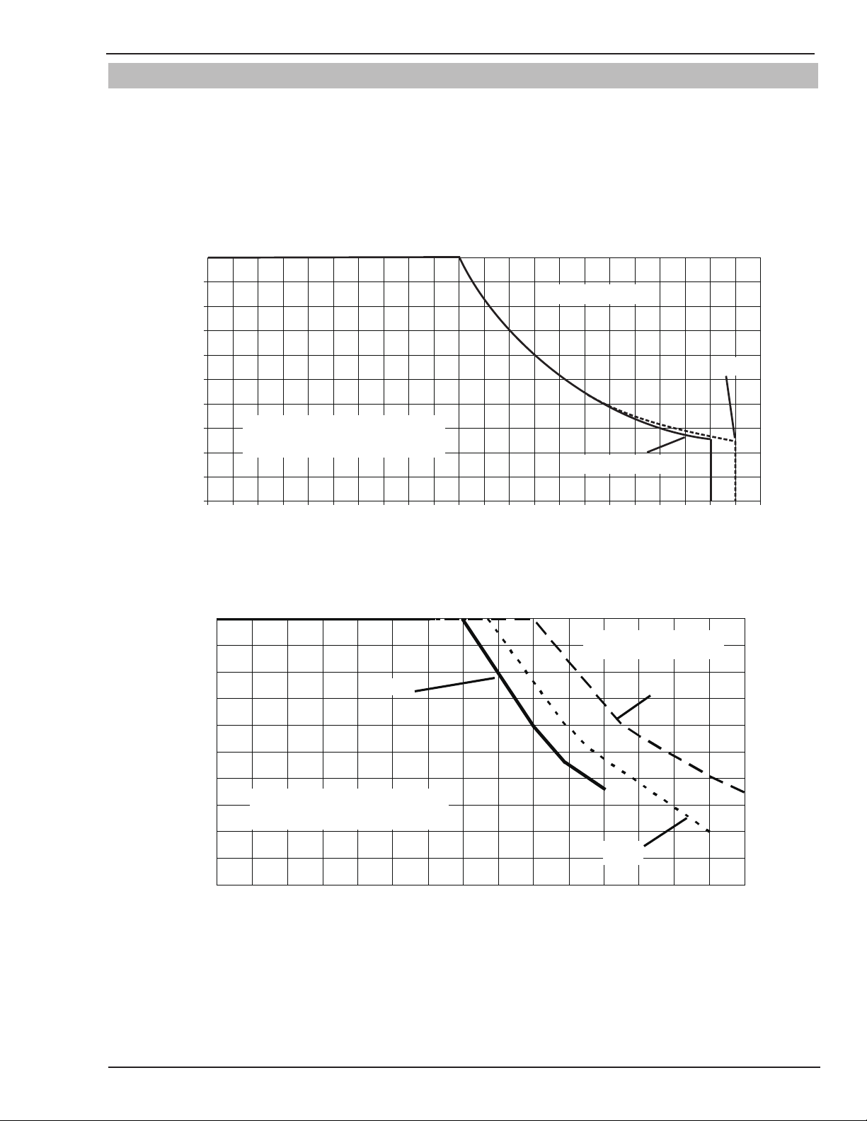
2.08 Duty Cycle
The rated duty cycle of a Welding Power Source, is a statement of the time it may be operated at its rated welding
current output without exceeding the temperature limits of the insulation of the component parts. To explain the 10
minute duty cycle period the following example is used. Suppose a Welding Power Source is designed to operate at a
20% duty cycle, 210 amperes at 24.5 volts. This means that it has been designed and built to provide the rated am-
perage (210A) for 2 minutes, i.e. arc welding time, out of every 10 minute period (20% of 10 minutes is 2 minutes).
During the other 8 minutes of the 10 minute period the Welding Power Source must idle and allowed to cool. The
thermal cut out will operate if the duty cycle is exceeded.
10 20 30 40 50 60 70 80 90 100 110 120 130 140 150 160 170 180 190 200 210 220
FABRICATOR 211i
Welding Current (AMPS)
SAFE OPERATING REGION
(MIG, TIG & STICK)
0
0
10
20
30
40
60
70
50
80
100
90
Duty Cycle (PERCENTAGE)
MIG
STICK / TIG
Art # A-11265
Figure 2-2: Fabricator 211i Duty Cycle on 208/230V AC
Welding Current (AMPS)
Duty Cycle (PERCENTAGE)
Art # A-11274
0
10
20
30
40
50
60
70
80
90
100
0102030405060708090100 110 120 130140 150
FABRICATOR 211i
SAFE OPERATING REGION
(MIG, TIG & STICK)
TIG
STICK
MIG
Figure 2-3: Fabricator 211i Duty Cycle on 115V AC
FABRICATOR 211i INTRODUCTION
INTRODUCTION 2-4 Manual 0-5157
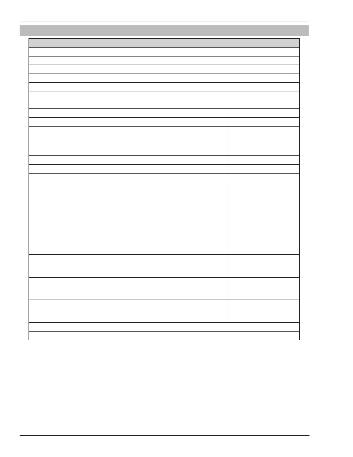
2.09 Specifications
Description Fabricator 211i Multi Process 3 in 1 Welder
Power Source Part No. W1004200
Power Source Dimensions H17.12" x W10.47" x D 24.29" (435mm x 266mm x D617mm)
Power Source Mass 57.3lb (26kg)
Cooling Fan Cooled
Welder Type Multi Process Welding System
Applicable Standard CSA E60974-1-00 / UL60974-1 / IEC 60974-1
Number of Phases Single Phase
Nominal Supply Voltage 208/230 VAC ± 10% 115VAC± 10%
Nominal Supply Frequency 50/60Hz 50/60HZ
Welding Current Range
MIG Mode
STICK Mode
TIG Mode
10-210 Amps
10-200 Amps
10-200 Amps
10-140 Amps
10-110 Amps
10-150 Amps
Wirefeed Speed Range 100 - 600 IPM 100 - 400 IPM
MIG Welding Voltage Range 14.5 - 24.5V DC 14.5 - 19V DC
Nominal OCV 70V DC
Effective Input Current (I1eff)
for MIG (GMAW/FCAW)
for STICK (SMAW)
for LIFT TIG (GTAW)
14.4A/11.2A
16.8A/15.8A
11.7A/11.5A
15.5A
17.8A
17.4A
Maximum Input Current (I
1max)
for MIG (GMAW/FCAW)
for STICK (SMAW)
for LIFT TIG (GTAW)
32.2A/25.0A
33.6A/31.6A
23.3A/22.9A
24.5A
30.1A
29.4A
Single Phase Generator Requirement 7.5 kVA *3.7 kVA
MIG (GMAW/FCAW) Welding Output, 104°F, 10 min. 210A @ 20%,24.5V
122A @ 60%, 20.1V
95A @ 100%, 18.8V
110A @ 45%,19.5V
99A @ 60%, 19.0V
77A @ 100%, 17.9V
STICK (SMAW) Welding Output,1040°F, 10 min. 200A @ 25%,28.0V
130A @ 60%, 25.2V
101A @ 100%, 24.0V
110A @ 35%,24.4V
90A @ 60%, 23.6V
70A @ 100%, 22.8V
TIG (GTAW) Welding Output, 104°F, 10 min. 200A @ 25%,18.0V
130A @ 60%, 15.2V
101A @ 100%, 14.0V
150A @ 35%,16.0V
115A @ 60%, 14.6V
90A @ 100%, 13.6V
Open Circuit Voltage 70 V
Protection Class IP23S
Table 2-1: Fabricator 211i Specifications
Note 1: The Effective Input Current should be used for the determination of cable size & supply requirements.
Note 2: Motor start fuses or thermal circuit breakers are recommended for this application. Check local require-
ments for your situation in this regard.
Note 3: Generator Requirements at the Maximum Output Duty Cycle.
* Some 115 VAC, 15 amp/20 amps electrical outlets fitted with GFCI (Ground Fault Circuit Interrupt) protection
against a nuisance trip with this equipment due to worn or out of tolerance components in the GFCI. In such cases
have the 115 VAC, 15 amp/20 amp FGCI electrical outlet replaced by a qualified electrical trades person.

INTRODUCTION FABRICATOR 211i
Manual 0-5157 2-5 INTRODUCTION
NOTE
The recommended time delay fuse or circuit breaker size for 115V is 30 amp. An individual branch circuit
capable of carrying 30 amperes and protected by fuses or circuit breaker is recommended for this applica-
tion. Fuse size is based on not more than 200 percent of the rated input amperage of the welding Power
Source (Based on Article 630, National Electrical Code)
Tweco continuously strives to produce the best product possible and therefore reserves the right to change,
improve or revise the specifications or design of this or any product without prior notice. Such updates or
changes do not entitle the buyer of equipment previously sold or shipped to the corresponding changes,
updates, improvements or replacement of such items
.
The values specified in the table above are optimal values, your values may differ. Individual equipment
may differ from the above specifications due to in part, but not exclusively, to any one or more of the fol-
lowing; variations or changes in manufactured components, installation and conditions and local power
grid supply conditions.
 Loading...