


Operator’s Manual
Wide-CutTM 33"
Combination Mower
Models 753B
F753B
(fuel tank styles vary by engine model)
IMPORTANT:READ SAFETY RULES AND INSTRUCTIONS CAREFULLY
Warning: This unit is equipped with an internal combustion engine and should not be used on or near any unimproved forest-covered, brush-cov- ered or grass-covered land unless the engine’s exhaust system is equipped with a spark arrester meeting applicable local or state laws (if any). If a spark arrester is used, it should be maintained in effective working order by the operator. In the State of California the above is required by law (Section 4442 of the California Public Resources Code). Other states may have similar laws. Federal laws apply on federal lands. A spark arrester for the muffler is available by contacting the service department at Troy-Bilt LLC, P.O. Box 361131 Cleveland, Ohio 44136-0019.
TROY-BILT LLC, P.O. BOX 361131, CLEVELAND, OH 44136-0019
PRINTED IN USA |
FORM NO. 770-10602F |
|
(12/2003) |

TABLE OF CONTENTS
Content |
Page |
Safety . . . . . . . . . . . . . . . . . . . . . . . . . . . . . . . . . . . . . . . . . . . . . . . . . . . . . . . . . . . . . . . . . . . 1
Assembly. . . . . . . . . . . . . . . . . . . . . . . . . . . . . . . . . . . . . . . . . . . . . . . . . . . . . . . . . . . . . . . . . 4
Features and Controls. . . . . . . . . . . . . . . . . . . . . . . . . . . . . . . . . . . . . . . . . . . . . . . . . . . . . . . 8
Operation . . . . . . . . . . . . . . . . . . . . . . . . . . . . . . . . . . . . . . . . . . . . . . . . . . . . . . . . . . . . . . . . 11
Maintenance . . . . . . . . . . . . . . . . . . . . . . . . . . . . . . . . . . . . . . . . . . . . . . . . . . . . . . . . . . . . . . 16
Off-Season Storage . . . . . . . . . . . . . . . . . . . . . . . . . . . . . . . . . . . . . . . . . . . . . . . . . . . . . . . . 24
Lubrications. . . . . . . . . . . . . . . . . . . . . . . . . . . . . . . . . . . . . . . . . . . . . . . . . . . . . . . . . . . . . . . 25
Troubleshooting . . . . . . . . . . . . . . . . . . . . . . . . . . . . . . . . . . . . . . . . . . . . . . . . . . . . . . . . . . . 27
Parts List . . . . . . . . . . . . . . . . . . . . . . . . . . . . . . . . . . . . . . . . . . . . . . . . . . . . . . . . . . . . . . . . . 28
Warrany Information . . . . . . . . . . . . . . . . . . . . . . . . . . . . . . . . . . . . . . . . . . . . . . . . . . . . . . . . Back Cover
FINDING MODEL NUMBER
This Operator’s Manual is an important part of your new Wide-CutTM mower. It will help you assemble, prepare and maintain the unit for best performance. Please read and understand what it says.
Before you start assembling your new equipment, please locate the model plate on the equipment and copy the information from it in the space provided below. This information is very important if you need help from our Customer Support Department or an authorized dealer.
•You can locate the model number by looking at the rear surface of the mower frame. A sample model plate is explained below. For future reference, please copy the model number and the serial number of the equipment in the space below
Copy Model Number Here
 TROY-BILT LLC Copy Serial Number Here
P. O. BOX 361131
www.troybilt.com CLEVELAND, OH 44136
330-558-7220
800-520-5520
ENGINE INFORMATION
The engine manufacturer is responsible for all engine-related issues with regards to performance, power-rating, specifications, warranty and service. Please refer to the engine manufacturer’s Owner’s/Operator’s Manual packed separately with your unit for more information.
CALLING CUSTOMER SUPPORT
If you have difficulty assembling this product or have any questions regarding the controls, operation or maintenance of this unit, please call the Customer Support Department.
Call 1- (330) 558-7220 or 1- (800) 520-5520 to reach a Customer Support representative. Please have your unit’s model number and serial number ready when you call. See previous section to locate this information. You will be asked to enter the serial number in order to process your call .
For more details about your unit, visit our website at www.troybilt.com
Section1 Safety
|
|
|
|
|
|
|
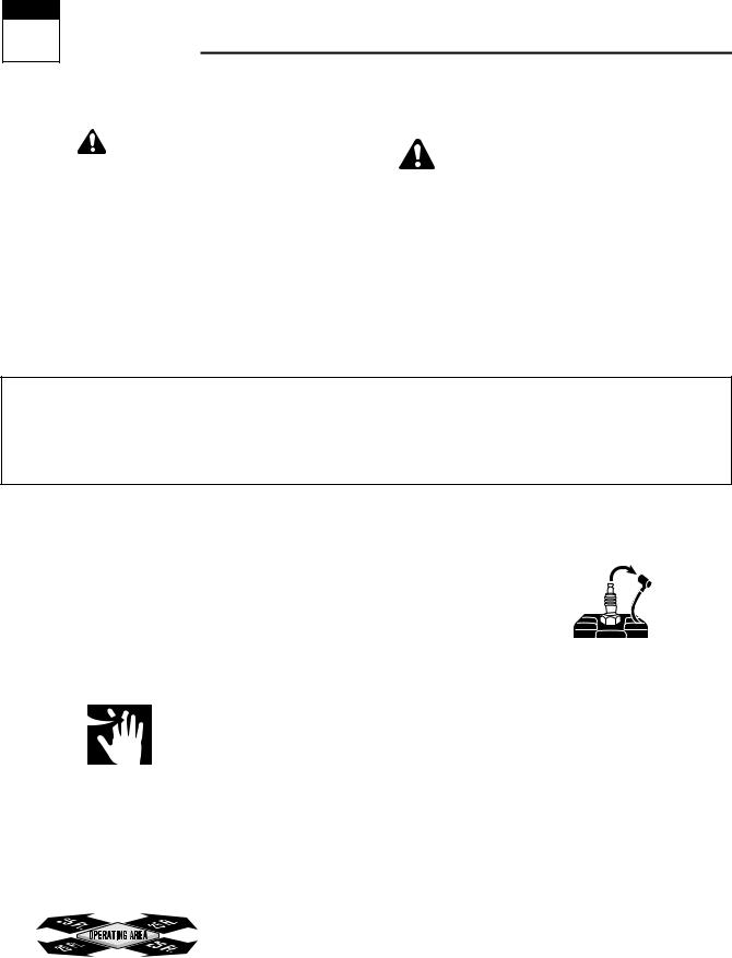
Safety Alert Symbol |
|
|
|
|
WARNING: |
|
|
|
|
|
|
|
|
This is a safety alert symbol. It is used in this |
||
|
|
|
|
|
|
|
Owner’s Manual to alert you to potential |
|
|
|
|
|
|
|
|
|
|
|
|
|
|
|
|
|
The engine exhaust from this product contains |
|
hazards. Whenever you see this symbol, read and obey the |
||||
|
chemicals known to the State of California |
|
|||||
|
|
safety message that follows it. Failure to obey the safety |
|||||
|
to cause cancer, birth defects, or other reproduc- |
|
message could result in personal injury or property |
||||
|
tive harm. |
|
damage. |
||||
|
|
|
|
|
|
|
|
|
|
|
|
|
|
|
|
IMPORTANT
Safe Operation Practices for Walk-Behind Mowers
This cutting machine is capable of amputating hands and feet and throwing objects. Failure to observe the following safety instructions could result in serious injury or death.
I.GENERAL OPERATION
1.Read, understand, and follow all instructions on the machine and in the manuals. Be thoroughly familiar with the controls and the proper use of the mower before starting.
2.Do not put hands or feet near or under rotating parts. Keep clear of the mower blade and discharge opening at all times.
3.Only allow responsible individuals, who are familiar with the instructions, to operate the mower.
4.Clear the area of objects such as rocks, toys, wire, bones, sticks, etc., which could be picked up and thrown by the blade.
5.Be sure the area is clear of other people before mowing. Stop mower if anyone enters the area. Keep bystanders at least 25 feet away from the area of operation.
6.Do not operate the mower when barefoot or wearing open sandals. Always wear substantial foot wear.
7.Do not pull mower backwards unless absolutely necessary. Look down and behind before and while moving backwards.
8.Do not operate the mower without proper guards, plates, grass catcher or other safety protective devices in place.
9.Refer to provided instructions for proper operation and installation of accessories. Only use accessories approved by Garden Way
Incorporated.
10.Stop the blade when crossing gravel drives, walks, or roads.
11.Stop the engine and disconnect the spark plug wire from the spark plug
whenever you leave the unit, before cleaning the mower or unclogging the chute.
12.Shut the engine off, wait until the blade comes to a complete stop, and disconnect the spark plug wire before installing or removing the mulcher cover or the optional grass catcher. Make certain that the grass catcher is securely attached before operating the mower. Empty the grass catcher after each use– decomposing debris could generate enough heat to catch fire.
13.Mow in daylight or good artificial light.
14.Do not operate the mower while under the influence of alcohol or drugs.
1

Section 1: Safety
15.Never operate mower in wet grass.
Always be sure of your footing; keep a firm hold on the handle and walk; never run.
16.Disengage the Wheel Drive Lever on self-propelled models before starting the engine.
17.If the unit should start to vibrate abnormally, stop the engine and disconnect the spark plug wire. Then check immediately for the cause.
Vibration is generally a warning of trouble.
18.Always wear safety goggles or safety glasses with side shields when operating mower.
19.Watch for traffic when operating near, or when crossing roadways.
20.Never attempt to carry children or other passengers on the mower. They could fall off and be seriously injured, or they could interfere with the safe operation of the mower.
21.Check the operation of the Operator
Presence Control Bar before each use. See the Maintenance Section of this manual for instructions. If the engine runs longer than three seconds after the Operator Presence Control Bar is released, the system is not working properly. Immediately contact your local service dealer or the factory Technical Service Department for instructions. Do not use the mower until the mechanism is repaired.
22.The mower is equipped with a safety discharge chute, comes with special mulcher covers, and offers an optional grass catcher. The safety discharge chute must be working properly at all times. Never attempt to disconnect or otherwise cause this discharge chute to cease working. If used, mulcher cover or grass catcher attachment must be installed properly and function correctly. Do not use your equipment otherwise.
23.Never run the engine in an enclosed area. Engine exhaust contains carbon monoxide, a deadly gas that is odorless, colorless, and tasteless. Always run the engine outdoors and make sure there is adequate ventilation.
II. SLOPE OPERATION
Slopes are a major factor related to slip and fall accidents which can result in severe injury. All slopes require extra caution. If you feel uneasy on a slope, do not mow it.
DO:
Mow across the face of slopes; never up and down. Exercise extreme caution when changing direction on slopes. Avoid slopes greater than
15o.
Remove objects such as rocks, tree limbs, etc.
Watch for holes, ruts, or bumps. Tall grass can hide obstacles.
DO NOT:
Do not mow near drop-offs, ditches, or embankments. The operator could loose footing or balance.
Do not mow excessively steep slopes.
Do not mow on wet grass. Reduced footing could cause slipping.
III. CHILDREN
Tragic accidents can occur if the operator is not alert to the presence of children. Children are often attracted to the mower and to the mowing activity.
Never assume that children will remain where you last saw them.
1.Keep children out of the mowing area and under the watchful care of a responsible adult.
2.Be alert and turn mower off if children enter the area.
3.Before and while moving backwards, look behind and down for small children.
4.Never allow children to operate the mower.
5.Use extra care when approaching blind corners, shrubs, trees, or other objects that may obscure vision.
IV. SERVICE
1.Use extra care in handling gasoline and other fuels. They are flammable and their vapors are explosive.
a)Use only an approved container.
b)Never remove gas cap or add fuel when the engine is running. Allow engine to cool before refueling. Do not smoke.
c)Never refuel the machine indoors.
d)Never store the machine or fuel container inside where there is an open flame, such as a water heater, etc.
e)Move mower away from any gasoline fumes before starting the engine.
2.Never run an engine inside a closed area.
3.Never make adjustments or repairs with the engine running. Disconnect the spark plug wire and keep the wire away from the plug to prevent accidental starting.
4.Keep all nuts and bolts, especially the blade attachment bolts, tight and keep equipment in good condition.
5.Never tamper with safety devices. Check their operation regularly.
6.Keep mower free of grass, leaves or other debris build-up. Clean up oil or fuel spillage. Allow mower to cool before storing.
7.After striking an object, stop the engine and disconnect the spark plug wire. Inspect the mower and repair, if necessary, before restarting.
8.Never attempt to make mower cutting height adjustments while the engine is running.
9.Grass catcher components are subject to wear, damage and deterioration, which could expose moving parts or allow objects to be thrown.
Frequently check components and replace with factory recommended parts, when necessary.
2

Section 1: Safety
10.Mower blades are sharp and can cut. Wrap the blade or wear gloves, and use extra caution when servicing them.
11.Do not change the engine governor setting or overspeed the engine.
12.Do not touch engine parts which may be hot from operation. Allow parts to cool completely before inspecting, cleaning or repairing the mower.
13.To access the underside of the mower, tip the mower rearward. Do not tip the mower forward or on either of its sides, unless specifically advised to do so in this manual.
14.Maintain or replace safety and instructional decals. Refer to the separate Parts Catalog for replacement decal information.
15.For units equipped with electric start:
a)Batteries produce explosive gases. Keep sparks, flame, cigarettes, etc., away. Ventilate the area when charging the battery. Do not charge the battery in an airtight space.
b)Do not use a battery charger other than the one provided with the mower.
c)The battery contains toxic materials. Do not damage the battery case. If the case is broken or damaged, avoid contact with the battery contents.
d)Properly dispose of a damaged or worn out battery. Check with local authorities for proper disposal methods.
e)Do not short circuit the battery.
Severe burns and fire can result.
SAFETY DECALS
Make certain all safety decals on this equipment are kept clean and in good condition. The decals are shown (at reduced sizes) below. If you need a replacement decal, please refer to the Parts Catalog that accompanied this Manual.
 WARNING
PINCH POINTS
Do not operate without all belt guards in place.
On left side of mower deck
Beneath belt/pulley cover
On Control Panel (for electric start model)
On Control Panel (for recoil start model) |
On discharge chute |
|
3
Section2 Assembly
 WARNING
To prevent personal injury or property damage, do not attempt to start the engine until all assembly steps are complete and you have read and understand the safety, controls and operating instructions in this manual.
INTRODUCTION
Please carefully follow these assembly steps to properly prepare your machine for use. We recommend that you read this Section in its entirety before beginning assembly.
NOTE: All references to left, right, front and rear of the machine are determined by standing behind the handlebars and facing the direction of forward travel.
INSPECTION AFTER DELIVERY
Inspect the shipping crate and machine immediately after delivery. Make sure neither the carton/crate nor the contents have been damaged.
If you find or suspect any damage, contact the carrier (trucking company) immediately. Inform them of the specific damage and that you wish to file a claim.
To protect your rights, be sure to put this in writing to the carrier within 15 days. The carrier will let you know how to proceed with your claim. Please let us know if you need any assistance.
TOOLS/MATERIALS NEEDED:
•Wire Cutter
•Two 7/16” Wrenches
•3/8” Wrench
•1/2” Wrench
•Scissors or Pen Knife
•Needle-nose Pliers
•Tire Gauge
ASSEMBLY STEPS
STEP 1: Unpacking Mower
NOTE: LEFT and RIGHT sides of the unit are as viewed from the operator’s position behind the handlebars.
1.Cut straps, if present, securing unit to pallet. Leave unit on pallet during assembly (to safely remove unit from pallet, wait until you have completed assembly steps 1-4).
2.Remove any protective packaging from around the handlebars. Cut the plastic tie straps holding the control rods and struts to the handlebars.
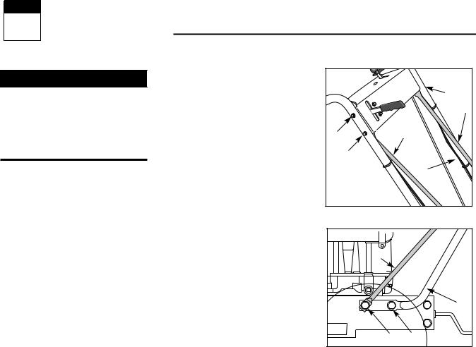
STEP 2: Attach Handlebars to Engine Deck
NOTE: Four screws (D, Figure 2-2) are used to connect the handlebars to the engine deck. At the factory, two of these screws (front) are threaded directly into lock nuts welded to the back sides of the deck. The remaining two screws (rear) secure the lower handle to the deck.
1.Remove and save the two 5/16"-18 x
3/4" screws (front) mentioned in the
NOTE above.
2.Loosen, but do NOT remove, the two
5/16"-18 x 3/4" screws (rear). Leave the cardboard insert found between the lefthand handlebar and engine deck, in place.
3.Carefully pivot the handlebars over the engine and position the handlebar ends (E, Figure 2-2) against the sides of the engine deck. Do not alloow the handlebars to rub against the engine while pivoting them.
4.Loosely secure the right-hand handlebar end to the deck by reinserting the screw (D, Figure 2-2) removed earlier. Do not secure the left-hand handle at this point in assembly.
5.Remove the cardboard insert from between the left-hand handlebar and engine deck
6.Remove the nut from the lower screw
(B, Figure 2-1) which secures the console to the handlebar on the left-hand
|
B |
|
A |
F |
A |
B |
|
|
C |
Figure 2-1 |
|
A |
|
|
E |
D |
D |
Figure 2-2: Attach handlebars and struts to engine deck.
side of the unit.
7.Position a handlebar strut’s smaller hole (A, Figure 2-1) over the screw (B, Figure 2-1) on the INSIDE of the console, with the strut’s flat side against the console.
8.Using the nut removed earlier, secure the strut to the console/handlebar.
9.Align the loose end of the left-hand handlebar strut (A, Figure 2-2) over the front hole in the handlebar end. Secure the strut and handlebar to the deck with the 5/16"-18 x 3/4" screw (D, Figure 2-2) removed earlier.
10.Remove the screw (front) that is loosely securing the right-hand handlebar end to the deck. and repeat 6-9 on the right-hand side of the unit.
11.On both sides of the unit, securely tighten the screws (D, Figure 2-2) at the lower ends of the handlebar before tightening the screws (B & F, Figure 2-1) on the console.
4
Section 2: Assembly
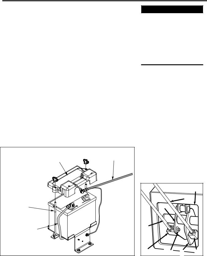
STEP 3 ATTACHING THE BATTERY CABLES (MODEL F753B)
The positive battery terminal is marked Pos. (+). The negative battery terminal is marked Neg. (–).
The mower is shipped with the positive (Red) cable secured to the positive terminal (+) on the battery. Attach the ground (Black) cable to the negative terminal (–) on the battery, as follows:
1.Remove the plastic battery cover (G, Figure. 2-3) by unthreading the two wing nuts (H, Figure. 2-3) which secure it to the battery hold-down rods (I, Figure. 2- 3)
2.Remove the hex bolt and hex nut from the ground cable / heavy black wire
(E, Figure. 2-3).
3.Secure the ground cable to the negative battery terminal (–) with the bolt and hex nut just removed.
4.Resecure the battery cover.
IMPORTANT:
•If the battery is put into service after the date shown on top of battery, charge the battery as instructed in the Maintenence section of this manual prior to operating the mower.
STEP 4: Attach Control Rods
A. Attach Wheel Drive Control Rod
1.Locate the wheel drive control rod (F,
Figures 2-4A & 2-7) and remove the angled end from the left handlebar by removing the hairpin clip which secures it to the Wheel Drive Control lever (V,
Figure 2-4A)
2.At left side of engine deck, insert swivel block (H, Figures 2-4 & 2-5) on wheel drive control rod into wheel drive control arm (U, Figure 2-4).
3.Add a 5/16" washer (A, Figure 2-4) and secure with a hairpin clip (B).
4.At upper end of control rod, re-insert the angled end into the Wheel Drive
Control lever (V, Figure 2-4A) and reattach with hairpin clip (BB) removed earlier.
B. Attach Operator Presence Control
Rod
1. Locate the Operator Presence Control rod (E, Figures. 2-4 and 2-5). At bottom of control rod, insert swivel block (G, Figures 2-4 & 2-5) into control arm (T,
Figure 2-4).
H |
Black |
(Negative Cable) |
|
G |
|
H |
|
I |
|
Red |
|
(Positive Cable) |
|
Figure 2-3: Connect wire terminals to battery terminals.
 WARNING
Control rods are adjusted at the factory and should not require additional adjustment during assembly. After assembling unit, control rod adjustment should be checked (and re-adjusted, if necessary) according to information in Maintenance Section.
Failure to follow this instruction could result in severe personal injury or property damage.
2. Add one 5/16" washer and secure with hairpin clip.
C. Attach Blade Drive Control Rod
1.Locate the blade drive control rod (C, Figure 2-5). Insert one end of control rod into blade drive bracket (D, Figure 2-5).
Add one 5/16" washer and attach with hairpin clip (CC).
2.Insert the other end of rod into bottom end of Blade Drive Control lever (J, Figure 2-5). Add one 5/16" washer and attach with hairpin clip (AA).
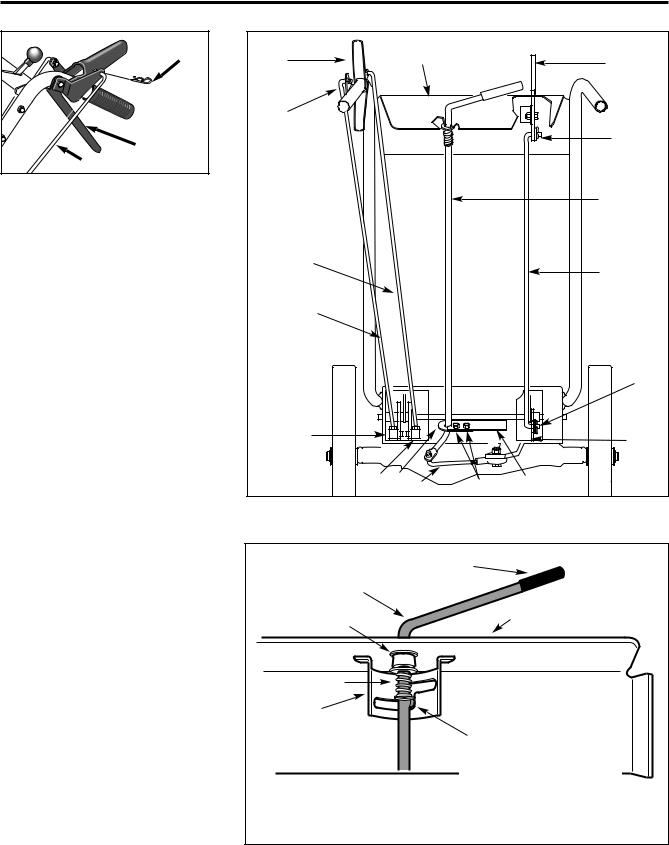
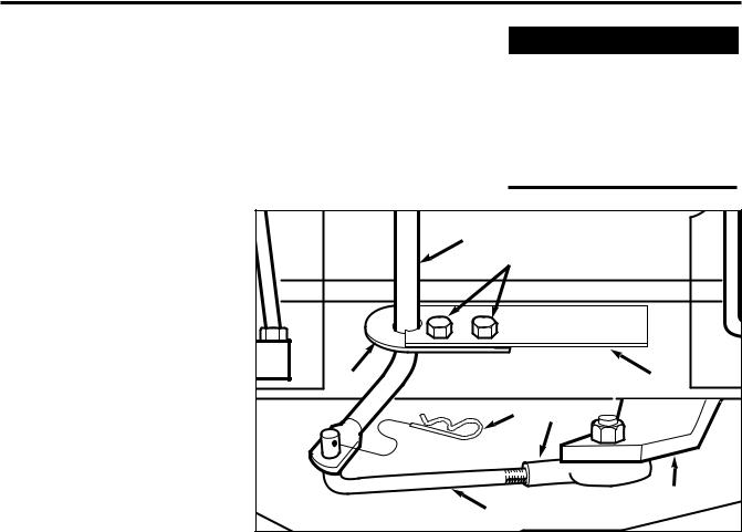
D. Attach and Adjust Gear Select Lever
NOTE: The retaining plate (N, Figure 2-5) mentioned in the following steps is secured to the rear of the mower with two screws (O, Figure 2-5) and 1/4”-20 locknuts. Remove the retaining plate and save it, along with the two screws, before proceeding with assembly.
|
|
|
W |
|
|
|
E |
|
U |
|
|
F |
|
|
|
H |
A, B |
T |
G |
Figure 2-4: Left-hand control rods detail.
5
Section 2: Assembly
BB |
V |
F |
Figure 2-4A: Attach wheel drive control rod to lever.
1.Remove the vinyl grip (B, Figure 2-6) from the gear select lever (I). Place the wood edge against the edge of the grip and slowly pull off the grip.
2.Insert nylon bushing (Z, Figure 2-6) up into console (L).
3.Slide spring and washers (J) down onto gear select lever.
4.Insert gear select lever (I) up through nylon bushing (Z) in handlebar console
(L). Guide pin (K) on gear select lever into groove in shift quadrant (P).
5.Hold lower part of gear select lever (I,
Figure 2-7) against bracket (M). Position retaining plate (N), removed earlier, as shown in Figure 2-7 (plate below bracket). Secure plate with two 1/4"-20 x 1/2" screws (O) and 1/4”-20 locknuts removed earlier.
6.Slide grip (B, Figure 2-6) back onto gear select lever (I).
7.Rotate gear select lever (I, Figures 2-
6& 2-7) clockwise until spur (K - short rod) on gear select rod stops in the neutral position detent on the shift pattern quadrant (Figure 2-6).
8.Move shift arm (X, Figure 2-7) from side to side as necessary into each transmission gear detent until transmission is in neutral.
NOTE: Moving shift arm (X) all the way to the left, and then one notch back to the right, should put transmission into neutral. When transmission is in neutral, unit will move freely when pushed while holding the Operator Presence Control lever (W, Figure 2-5) down. If transmission is NOT in neutral, there will be a slight drag on the wheels when pushing unit.
W |
|
L |
|
J |
|
|
|
||
V |
|
|
|
|
|
|
|
|
AA |
|
|
|
|
I |
E |
|
|
|
C |
|
|
|
|
|
F |
|
|
|
|
|
|
|
|
CC |
H |
|
|
|
D |
G |
N |
P |
O |
M |
|
Figure 2-5: Rear view of control rods.
|
B |
|
I |
Z |
L |
|
|
J |
|
P |
|
|
K |
Pin (K) must be in this detent when transmission neutral is adjusted.
Figure 2-6: Detail – Gear Select Lever in Neutral (N) position.
6
Section 2: Assembly
9. When shift arm (X) is in neutral position, rotate shift link (P) toward end of gear select lever rod (I). Adjust length of shift link (P) as necessary to fit into hole in bottom of gear select lever (I).
NOTE: Pin (K) on Gear Select Lever (I) must be held in the neutral position detent on the shift quadrant (see Figure
2-6) while shift link (P, Figure 2-7) is adjusted.
10. Insert hooked end of shift link (P, Figure 2-7) into hole in bottom end of gear select lever (I) and secure with hairpin clip (Q).
NOTE: It may be necessary to lift gear select lever (I) to install shift link (P).
11.Remove unit from shipping crate. To remove, hold down Operator Presence Control lever (W, Figure 2-5) which releases the wheel brake.
12.With unit on level ground, hold down Operator Presence Control lever (W, Figure 2-5) and push unit forward and backward. The wheels should move freely. If not, adjust length of shift link (P, Figure 2-7) as necessary.
13.Put the Gear Select Lever in neutral (N), release all of the control levers and try to push the unit forward and backward. The wheels should not turn. If they do turn, an adjustment is necessary. DO NOT OPERATE THE UNIT UNTIL THE WHEEL BRAKE MECHANISM
HAS BEEN ADJUSTED AND IS WORK-
ING PROPERLY. See “Wheel Brake Adjustment” in Section 5 “Maintenance.”
STEP 5: Secure Wire Harness
1. At the unattached end of the electrical wire harness, there are four wires attached to a large plastic connector and two wires attached to a small plastic connector. . Plug the large connector into the bottom of the ignition keyswitch that is located on the underside of the handlebar console (not pictured).
3. Use two cable ties to secure the wire harness to the right handlebar and away from any moving parts. Place the ties an equal distance apart.
STEP 6: Check Motor Oil Level
1.Move mower to a level area. Press and hold Operator Presence Control lever (W, Figure 2-5) to move mower.
2.The mower is shipped with oil in the engine. However, you MUST check the oil level according to the instructions provided in the separate Engine Owner’s Manual included in the unit’s literature package before starting the mower.
 WARNING
Do not use the mower if the wheels continue to turn after releasing the Operator Presence Control and the
Wheel Drive Control.
Severe personal injury or property damage could result if this instruction is not followed.
I |
|
O |
|
N |
M |
Q |
Y |
|
X |
P |
|
Figure 2-7: Detail – Transmission Neutral Adjustment.
•Keep oil level at the FULL mark on the dipstick to avoid engine damage.
•Change oil according to schedule and instructions in Section 5 “Maintenance.”
STEP 7: Check Tire Pressure
1.Use a tire gauge to check the air pressure in the rear tires. The air pressure should be between 15-20 PSI (20 PSI maximum).
2.Keep both tires equally inflated to help prevent machine from pulling to one side.
STEP 8: After Assembling and
Before Using Unit
1.Read this entire Owner’s Manual for proper safety, operation and maintenance information.
2.Make sure spark plug wire is connected to spark plug before starting unit.
7
 Loading...