


21A-645A711
O m m 'w//////al&_,411111111111111F
/ m mllllllllllllllllml m
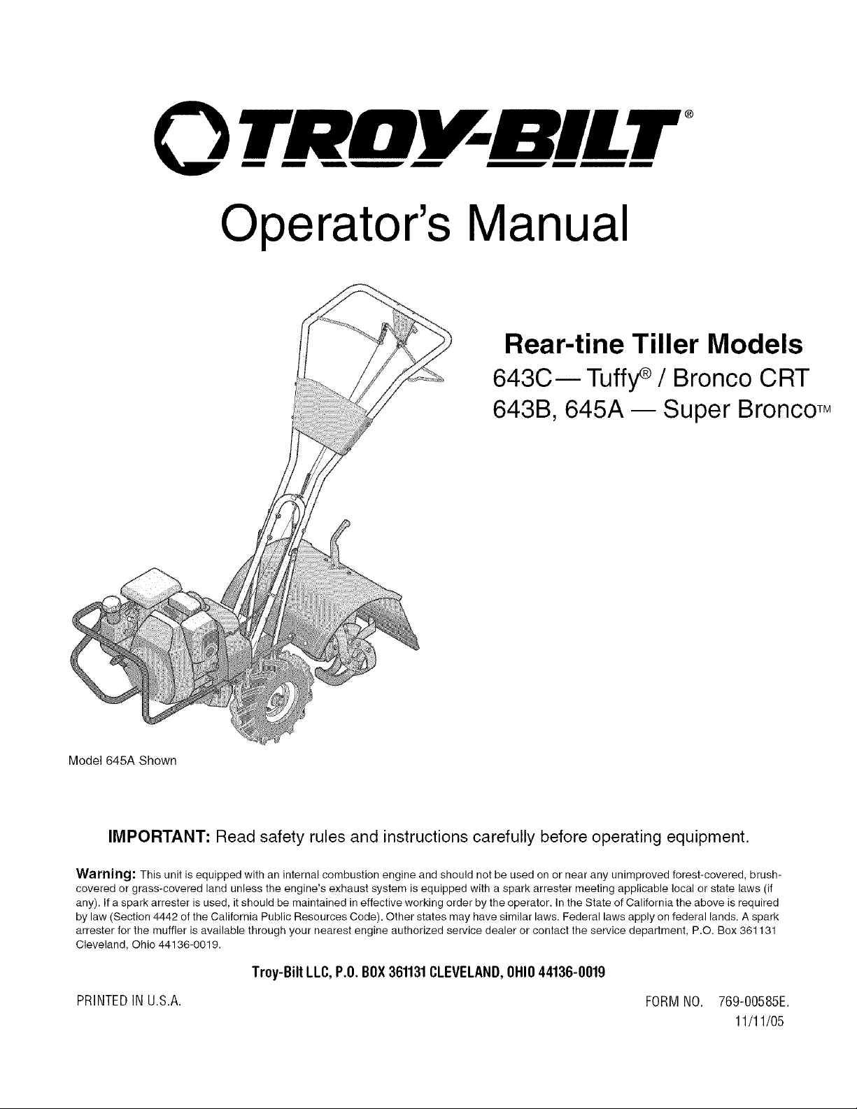
Operator's Manual
®
Rear-tine Tiller Models
643C m Tuffy¢ / Bronco CRT
643B, 645A -- Super BroncoTM
Mode1645A Shown
IMPORTANT: Read safety rules and instructions carefully before operating equipment.
Warning: This unit is equipped with an internal combustion engine and should not be used on or near any unimproved forest-covered, brush-
covered or grass-covered land unless the engine's exhaust system is equipped with a spark attester meeting applicable local or state laws (if
any). If a spark arrester is used, it should be maintained in effective working order by the operator. In the State of California the above is required
by law (Section 4442 of the California Public Resources Code). Other states may have similar laws. Federal laws apply on federal lands. A spark
arrester for the muffler is available through your nearest engine authorized service dealer or contact the service department, P.O. Box 361131
Cleveland, Ohio 44136-0019.
Troy-Bilt LLC, P.O.BOX361131CLEVELAND,OHIO44136-0019
PRINTEDINU.S.A. FORMNO. 769-00585E.
11/11/05
TABLEOFCONTENTS
Content Page Content Page
Customer Support 2 Maintenance 17
Safety 3 Off-season Storage 21
Assembly 6 Troubleshooting 22
Features and Controls 10 Parts List 24
Operation 12 Warranty Back Cover
FINDINGMODELNUMBER
This Operator's Manual is an important part of your new tiller. Itwill help you assemble, prepare and maintain the unit for
best performance. Please read and understand what it says.
Before you start assembling your new equipment, please locate the model plate on the equipment and
copy the information from it in the space provided below. A sample model plate is also given below. You can
locate the model plate by looking at the rear of the tine shield. This information will be necessary to use the
manufacturer's web site and/or help from the Customer Support Department or an authorized service dealer.
P. O. BOX 361131
www.troybilt.com CLEVELAND,OH44136
330-558-7220
866-840-6483_
Copy the model number here:
Copy the serial number here:
CUSTOMERSUPPORT
PleasedoNOTreturnthe unit totheretailer without firstcontactingCustomerSupport.
If you have difficulty assembling this product or have any questions regarding the controls, operation or maintenance of
this unit, you can seek help from the experts. Choose from the options below:
Visit troy-bilt.com for many useful suggestions. Click on Customer Support button and you
will get the four options reproduced here. Click on the appropriate button and help is
immediately available.
_!_I_O ,f__< <;:k_;_....._/ y'
7%%%'7_-'.........................................
Iilo I1 II ff bl _ll i {_1 7 7fl ,
/)_,'_'_ ;<;W";; jiI_)7,/_;7
;J< / I+ 1_,7_ .............. ......
< ........ ,,,,,
If you prefer to reach a Customer Support Representative, please call 1(866) 840-6483.
The engine manufacturer is responsible for all engine-related issues with regard to
performance, power-rating, specifications, warranty and service. Please refer to the engine
manufacturer's Owner's/Operator's Manual, packed separately with your unit, for more
information.
SECTION1: SAFETY
This machine meets voluntary safety stan-
dard B71.8-1996, which is sponsoredbythe
Outdoor Power Equipment Institute, Inc.,
and is published bythe American National
Standards Institute.
WARNING
The engine exhaust from this productcontains
chemicals known to the State of California to
cause cancer, birth defects or other reproduc-
tive harm.
SafetyAlertSymbol
,_ This is a safety alert symbol. It is used
in this manual and on the unit to alert
you to potential hazards. When you see
this symbol, read and obey the
message that follows it. Failure to obey
safety messages could result in
personal injury or property damage.
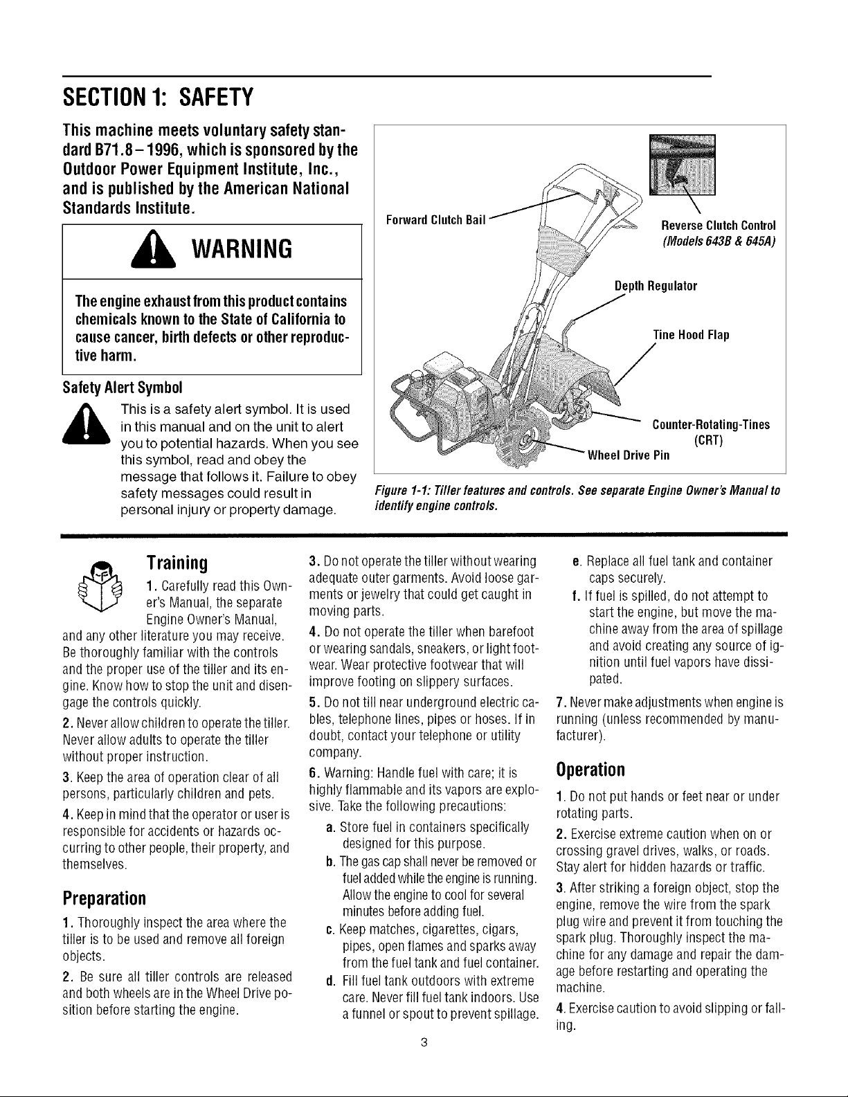
ForwardClutchBail
ReverseClutchControl
(Mode/s643B&645A)
DepthRegulator
TineHoodFlap
Counter-Rotating-Tines
(CRT)
Drive Pin
Figure 1-1: Tiller featuresand contre/s.See separateEngineOwner'sManua/ to
identifyenginecontre/s.
Training
1. Carefully readthis Own-
er's Manual,the separate
Engine Owner'sManual,
and any other literature you mayreceive.
Bethoroughly familiar with the controls
andthe proper useof the tiller and its en-
gine. Knowhowto stop the unit and disen-
gagethe controls quickly.
2. Neverallow childrento operatethetiller.
Neverallow adults to operatethe tiller
without proper instruction.
3. Keepthe area of operationclear of all
persons, particularly children and pets.
4. Keepin mindthat the operatoror user is
responsible for accidentsor hazardsoc-
curring to otherpeople,their property,and
themselves.
Preparation
1. Thoroughly inspect the areawherethe
tiller is to be usedand removeall foreign
objects.
2. Be sure all tiller controls are released
and both wheelsare inthe Wheel Drive po-
sition beforestarting the engine.
3. Donot operatethetiller without wearing
adequateouter garments. Avoid loose gar-
ments or jewelry that could get caught in
moving parts.
4. Donot operatethe tiller when barefoot
or wearing sandals, sneakers,or light foot-
wear.Wearprotective footwear that will
improve footing on slippery surfaces.
5. Donottill nearunderground electricca-
bles, telephone lines, pipes or hoses.If in
doubt, contactyour telephoneor utility
company.
6. Warning: Handlefuel with care; it is
highly flammableand its vaporsareexplo-
sive.Takethe following precautions:
a. Storefuel in containers specifically
designedfor this purpose.
b. Thegascapshall neverberemovedor
fueladdedwhiletheengineisrunning.
Allowthe engineto coolforseveral
minutesbeforeaddingfuel.
c. Keepmatches,cigarettes, cigars,
pipes, openflamesandsparks away
from thefuel tank and fuelcontainer.
d. Fillfuel tank outdoors with extreme
care.Neverfill fueltank indoors. Use
a funnel or spout to preventspillage.
e. Replaceall fueltank andcontainer
caps securely.
f. Iffuel isspilled, do not attempt to
start the engine,but move the ma-
chineawayfrom the areaof spillage
and avoid creating any source of ig-
nition until fuel vapors havedissi-
pated.
7. Nevermakeadjustments when engineis
running (unless recommendedby manu-
facturer).
Operation
1. Do not put hands or feetnear or under
rotating parts.
2. Exerciseextremecaution when on or
crossing gravel drives, walks, or roads.
Stay alert for hidden hazardsor traffic.
3. After striking a foreign object, stop the
engine, removethe wire from the spark
plug wire andprevent it from touching the
spark plug. Thoroughly inspect the ma-
chine for any damageand repairthe dam-
agebefore restarting and operatingthe
machine.
4.Exercisecautionto avoidslipping orfall-
ing.
5.Iftheunitshouldstarttovibrateabnor-
mally,stoptheengine,disconnectthe
sparkplugwireandpreventitfromtouch-
ingthesparkplug,andcheckimmediately
forthecause.Vibrationisgenerallya
warningoftrouble.
6.Stoptheengine,disconnectthespark
plugwireandpreventitfromtouchingthe
sparkplug,wheneveryouleavetheoperat-
ingposition,beforeuncloggingthetines,
orwhenmakinganyrepairs,adjustments
orinspections.
7.Takeallpossibleprecautionswhenleav-
ingthemachineunattended.Stoptheen-
gine.Disconnectthesparkplugwireand
moveitawayfromthesparkplug.Besure
thatbothwheelsareintheWheelDrivepo-
sition.
8.Beforecleaning,repairing,orinspect-
ing,stoptheengineandmakecertainall
movingpartshavestopped.Disconnect
thesparkplugwireandpreventitfrom
touchingthesparkplugtopreventacci-
dentalstarting.
9.Theflaponthetinehoodmustbedown
whenoperatingthetiller.
10.Neverusethetillerunlessproper
guards,plates,orothersafetyprotective
devicesareinplace.
11.Donotruntheengineinanenclosed
area.Engineexhaustcontainscarbon
monoxidegas,adeadlypoisonthatis
odorless,colorless,andtasteless.
12.Keepchildrenandpetsaway.
13. Neveroperatethe tiller underengine
powerif thewheels arein theFreewheel
position.Inthe Freewheelposition, the
wheelswill not hold the tiller back andthe
revolvingtines could propel thetiller rapid-
ly,possibly causingloss of control. Always
engagethe wheels with the wheel drive
pins in theWheel Drive position before
starting the engine or engaging the
tines_vheelswith the Forward Clutch Bail
(all models)or the ReverseClutchcontrol
(Models 643B& 645A only).
14. Be aware that the tiller may unex-
pectedlybounceupwardorjumpforward
if thetines shouldstrikeextremelyhard
packedsoil, frozenground,or buriedob-
stacleslike largestones, roots,or
stumps.
If indoubtaboutthe tilling conditions,al-
ways usethe following operating precau-
tionsto assistyouin maintainingcontrol
of thetiller:
a. Walk behindandto one side of the
tiller, usingone handon thehandle
barsRelax yourarm, but usea
securehandgrip.
b. Useshallowerdepthregulator
settings,working graduallydeeper
with each pass.
c. Useslowerenginespeeds.
d. Clearthetilling area of all large
stones,rootsor other debris.
e. Avoidusingdownwardpressureon
thehandlebars.If needbe, use
slight upwardpressureto keep the
tinesfrom diggingtoodeeply.
f. Beforecontacting hard packedsoil
at the endof a row,reduceengine
speedand lift the handlebarsto
raise the tines out of the soil.
g. In an emergency, stopthetinesand
wheels byreleasing whichever
clutch controlis engaged.Do not
attemptto restrainthetiller.
15. Donot overloadthe tiller's capacityby
attempting to till too deeply at too fast a
rate.
16. Neveroperate the tiller at high trans-
port speeds onhard or slippery surfaces.
Look behind and usecarewhen backing
up.
17. Donot operatethetiller on aslope that
is too steep for safety.When on slopes,
slow down and makesure you have good
footing. Neverpermit thetiller to freewheel
down slopes.
18. Neverallow bystandersnearthe unit.
19. Onlyuseattachmentsand accessories
that areapproved by the manufacturer of
the tiller.
20. Usetiller attachmentsand accessories
when recommended.
21. Neveroperatethe tiller without good
visibility orlight.
22. Neveroperatethe tiller if you aretired;
or underthe influence ofalcohol, drugs or
medication.
23. Operatorsshall not tamper with theen-
gine-governor settings onthe machine;
the governor controls the maximum safe
operatingspeedto protect the engineand
all movingparts from damagecaused by
overspeed.Authorized serviceshall be
sought if a problem exists.
24. Do not touch engine parts which may
behot from operation.Let parts cool down
sufficiently.
25. Pleaseremember:Youcan alwaysstop
the tines and wheels by releasingthe For-
ward Clutch Bailor on Models 643B &
645Athe ReverseClutchcontrol, (which-
evercontrol isengaged),or bymoving the
ignition switch and/orthrottle control lever
on the engineto "OFF" or "STOP".
26. Toload or unloadthe tiller, seethe in-
structions in Section4 of this Manual.
27. Useextreme caution when reversing
or pullingthe machinetowards you.
28. Startthe enginecarefully accordingto
instructions and with feetwell away from
the tines.
29. Neverpick up or carry a machinewhile
the engineis running.
MaintenanceandStorage
1. Keepthe tiller, attachmentsand acces-
sories in safeworking condition.
2. Checkall nuts, bolts, and screws for
proper tightness to besurethe equipment
is in safeworking condition.
3. Neverstore thetiller with fuel in thefuel
tank inside abuilding whereignition sourc-
esare presentsuchashot waterandspace
heaters,furnaces, clothes dryers, stoves,
electric motors, etc.). Allow the engine to
cool beforestoring the unit in any enclo-
sure.
4. Toreducethe chancesof a fire hazard,
keepthe enginefreeofgrass, leaves,or ex-
cessivegrease.
5. Storegasolinein acool, well-ventilated
area,safelyawayfrom anyspark- or
flame-producing equipment. Store gaso-
line in an approvedcontainer,safelyaway
from the reachof children.
6. Referto the Maintenancesections of
this Manualand the separateEngineOwn-
er'sManualfor instructions ifthe unitis to
bestored for an extendedperiod.
7. Neverperform maintenancewhilethe
engineis running orthe sparkplug wire is
connected,exceptwhen specifically in-
structed to do so.
8. Ifthe fueltank hasto be drained,dothis
outdoors.
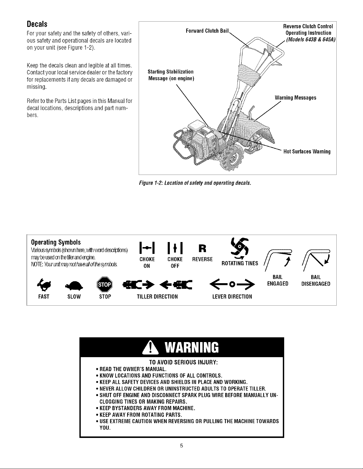
Decals
Foryour safety and the safetyof others, vari-
ous safety andoperational decalsare located
on your unit (seeFigure 1-2).
Keepthe decalsclean and legible atall times.
Contactyour localservicedealeror thefactory
for replacementsif any decalsaredamagedor
missing.
Referto the Parts List pagesin this Manualfor
decallocations, descriptionsand part num-
bers.
ForwardClutch Bail
StartingStabilization
Message(on engine)
ReverseClutch Control
OperatingInstruction
_ (Models 643B& 645A
WarningMessages
Hot Surfaces Warning
Figure1-2: Locationof safety and operatingdeca/s.
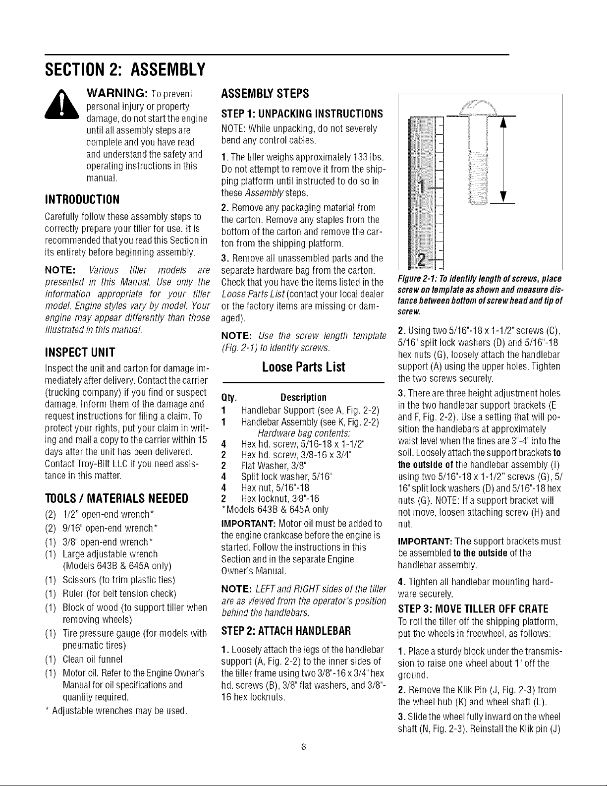
OperatingSymbols
Varioussymbols(shownhere,_dthworddescrip'dons)
maybeusedonte'dllerandengine.
NOTE:YourunihT_ynothaveallof_esymbols.
FAST SLOW STOP
I"1 I*1 R
CHOKE CHOKE REVERSE
ON OFF ROTATINGTINES
TILLERDIRECTION
<--o-->
LEVERDIRECTION
BAIL
ENGAGED
BAIL
DISENGAGED
TO AVOID SERIOUS INJURY:
* READTHEOWNER'SMANUAL.
* KNOWLOCATIONSANDFUNCTIONSOFALLCONTROLS.
* KEEPALLSAFETYDEVICESANDSHIELDSIN PLACEAND WORKING.
. NEVERALLOWCHILDRENORUNINSTRUCTEDADULTSTOOPERATETILLER.
° SHUTOFFENGINEANDDISCONNECTSPARKPLUGWIRE BEFOREMANUALLYUN-
CLOGGINGTINESORMAKINGREPAIRS.
° KEEPBYSTANDERSAWAYFROMMACHINE.
° KEEPAWAYFROM ROTATINGPARTS.
° USEEXTREMECAUTIONWHENREVERSINGOR PULLINGTHE MACHINETOWARDS
YOU.
SECTION2: ASSEMBLY
WARNING: Toprevent
personalinjury or property
damage,do notstart the engine
until all assemblysteps are
completeandyou have read
and understandthesafety and
operating instructions in this
manual.
INTRODUCTION
Carefullyfollow theseassemblysteps to
correctly prepareyour tiller for use. It is
recommendedthatyou readthis Sectionin
its entirety beforebeginning assembly.
NOTE: Various tiller models are
presented in this Manual. Use only the
information appropriate for your tiller
model. Enginestyles vary by model, Your
engine may appear differently than those
illustrated in this manual.
INSPECTUNIT
Inspect the unitand carton for damageim-
mediatelyafter delivery.Contactthe carrier
(trucking company) if you find or suspect
damage.Inform them of the damageand
request instructions for filing a claim. To
protect your rights, put your claim in writ-
ing and maila copyto the carrierwithin 15
days after the unit has beendelivered.
ContactTroy-Bilt LLCif you needassis-
tance inthis matter.
TOOLS/ MATERIALSNEEDED
(2) 1/2" open-end wrench*
(2) 9/16" open-endwrench*
(1) 3/8" open-endwrench*
(1) Largeadjustable wrench
(Models 643B & 645A only)
(1) Scissors (totrim plasticties)
(1) Ruler (for belttension check)
(1) Block of wood (to support tiller when
removing wheels)
(1) Tirepressure gauge(for models with
pneumatictires)
(1) Cleanoil funnel
(1) Motor oil. Refertothe EngineOwner's
Manualfor oilspecificationsand
quantityrequired.
* Adjustable wrenchesmay be used.
ASSEMBLYSTEPS
STEP 1: UNPACKING INSTRUCTIONS
NOTE:While unpacking, do not severely
bend any control cables.
1.Thetiller weighs approximately 133 Ibs.
Do notattempt to remove it from the ship-
ping platform until instructed to do so in
these Assembly steps.
2. Removeany packagingmaterial from
the carton. Removeany staples from the
bottom of the cartonand removethe car-
ton from the shipping platform.
3. Removeall unassembledparts andthe
separatehardwarebag from the carton.
Checkthat you havethe items listed in the
LooseParts List (contactyour localdealer
or the factory itemsare missing or dam-
aged).
NOTE: Use the screw length template
(Fig,2-1) to identify screws,
LooseParts List
Qty. Description
1 HandlebarSupport (seeA, Fig. 2-2)
1 HandlebarAssembly(seeK,Fig.2-2)
Hardwarebag contents:
4 Hexhd. screw, 5/16-18 x 1-1/2"
2 Hexhd. screw, 3/8-16 x 3/4"
2 FlatWasher,3/8"
4 Split lock washer,5/16"
4 Hex nut, 5/16"-18
2 HexIocknut,3_8"-16
*Models 643B & 645Aonly
IMPORTANT:Motor oil must beaddedto
the enginecrankcasebeforetheengine is
started. Followthe instructions inthis
Sectionand in the separateEngine
Owner's Manual.
NOTE: LEFTandRIGHTsides of thetiller
are as viewedfrom theoperator's position
behind the handlebars.
STEP 2: ATTACHHANDLEBAR
1. Looselyattachthe legs of thehandlebar
support (A, Fig. 2-2) to the innersides of
the tiller frame usingtwo 3/8"-16x3/4" hex
hd.screws (B),3/8" flat washers, and3/8"-
16 hexIocknuts.
_iiii
Figure2-1: Toidentifylengthofscrews,place
screwontemplateasshownandmeasuredis-
tancebetweenbottomofscrewheadandtipof
screw.
2. Usingtwo 5/16"-18x 1-1/2"screws (C),
5/16"split lock washers (D) and 5/16"-18
hexnuts (G), loosely attach the handlebar
support (A)usingthe upperholes.Tighten
thetwo screws securely.
3. Therearethree height adjustment holes
in the two handlebar support brackets (E
and F,Fig. 2-2). Usea setting that will po-
sition the handlebarsat approximately
waist levelwhenthetines are3"-4"intothe
soil. Looselyattachthe support bracketsto
theoutsideof the handlebarassembly (I)
usingtwo 5/16"-18x 1-1/2" screws (G), 5/
16"split lockwashers(D)and5/16"-18 hex
nuts (G). NOTE:If asupport bracketwill
not move, loosenattaching screw (H) and
nut.
IMPORTANT:The support bracketsmust
beassembledto theoutside ofthe
handlebarassembly.
4. Tightenall handlebarmounting hard-
waresecurely.
STEP 3: MOVE TILLER OFF CRATE
Toroll the tiller off the shipping platform,
put the wheels in freewheel, asfollows:
1. Placeasturdy block underthetransmis-
sion to raise one wheelabout 1" off the
ground.
2. Removethe Klik Pin (J, Fig. 2-3) from
the wheelhub (K) and wheelshaft (L).
3. Slidethe wheelfully inwardonthewheel
shaft (N,Fig. 2-3). Reinstallthe Klikpin (J)
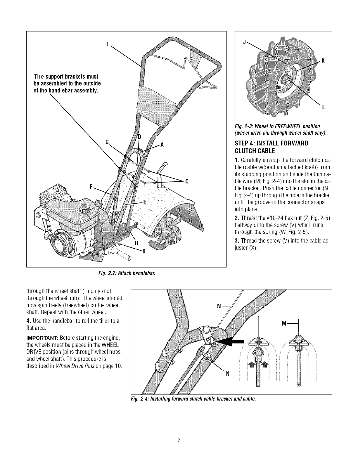
The supportbracketsmust
be assembledto theoutside
of the handlebarassembly.
Fig.2-3: WheelinFREEWHEELposition
(wheeldrivepin throughwheelshaftonly).
STEP 4: INSTALL FORWARD
CLUTCH CABLE
1. Carefullyunwrapthe forward clutch ca-
ble(cablewithout an attachedknob) from
its shipping position andslide the thin ca-
blewire (M, Fig.2-4) intothe slot in the ca-
blebracket. Pushthe cableconnector (N,
Fig.2-4) upthrough the holein thebracket
untilthe groove in the connector snaps
into place.
2. Threadthe#10-24 hexnut (Z, Fig. 2-5)
halfway ontothe screw (V)which runs
through the spring (W,Fig. 2-5).
3. Threadthe screw (V) into the cablead-
juster (X).
Fig. 2.2: Attachhandlebar.
through the wheel shaft (L) only (not
through thewheelhub). Thewheelshould
now spin freely (freewheel)on the wheel
shaft. Repeatwith the other wheel.
4. Usethe handlebarto roll the tiller to a
flat area.
IMPORTANT:Beforestarting the engine,
the wheels must beplacedin theWHEEL
DRIVEposition (pinsthrough wheelhubs
andwheelshaft). This procedureis
described in WheelDrivePins on page 10.
Fig. 2-4:/nstal/ing forward clutchcable bracketand cable.
4. Checkfor correcttension ontheforward
drive belt bytaking two measurementsof
the cablespring, as follows:
a.With the Forward Clutch Bail (Y,Fig. 2-
6) in an open (released)position, measure
the length ofthe cable spring (W) from the
outermost coil to the outermost coil.
b. Squeezethe ForwardClutch Bailagainst
the handlebar(see Fig. 2-7) and re-mea-
surethe spring length. Thebelt tension is
correct if this second measurementis be-
tween 1/16"to 3/16" longer thanthe first
measurement.If so,turn the hexnut (Z,
Fig. 2-7) tightly against the cable adjuster
(X) while preventing the cable adjuster
from turning.
c. Ifthe spring length is incorrect, you
must adjustthe cabletension asdescribed
in Checkingand Adjusting ForwardDrive
Belt Tensionin Section5. Incorrect cable
tension can result inbelt slippage (cable
tension too loose), or unintentional tine
movement when the clutch bail is in Neu-
tral (cabletension too tight).
Wm
: v
Fig.2-5: Cable
springand
adjuster.
W
Fig. 2-6: Attachforward
clutchcable spring to
forwardclutch bail
iiiiiiiiiiiiiiii
Fig. 2-7: Tocheckforwardbelt tension, take twomeasurementsof thelengthofthe coilsin the
spring-- first withthebah open, then withthe bah held against thehandlebar.
STEP 5: INSTALL REVERSECLUTCH
CABLE(MODELS643BAND 645A ONLY)
1. Unwrapthe reverseclutch cable (CC,
Fig.2-8 and Fig.2-9) from itsshipping po-
sition androute it up to the handlebar.Be
surethat the cableis routed beneaththe
Forward Clutch Bail.
2. Insertthecable(CC,Fig.2-8)through the
slot inthecablebracketandpositiontheflat
sideof thethreadedassemblynextto the
flat side of the hole.Slidethe hexnut (DD)
up the cable andtighten it securely.
3. Fastenthe reverseclutch cable to the
left side handlebarwith acabletie (EE,Fig.
2-9).
4. Testthefunction ofthe reverseclutch by
pulling out and releasingthe cable knob.
Theknob should return to its neutral posi-
tion (resting against bracket). If it doesn't,
contact your local dealeror Troy-Bilt LLC
for technical assistance.
Flat Side
Fig. 2-8: Install reverse cable bracketand
reverseclutchcable.
Fig. 2-9: Routereverse clutchcable (CC)as
shown.Attachwithcable tie (EE).
5! =-P6:CHECKTRAHSMiSSiOH
OILLEVEL
Thetransmission wasfilledwith gearoil at
thefactory. However,you shouldcheckthe
gear oil levelatthis time to makecertain it
is correct.
IMPORTANT:Donot operatethe tiller ifthe
gear oil level is low. Doingso will result in
severedamageto the transmission com-
ponents.
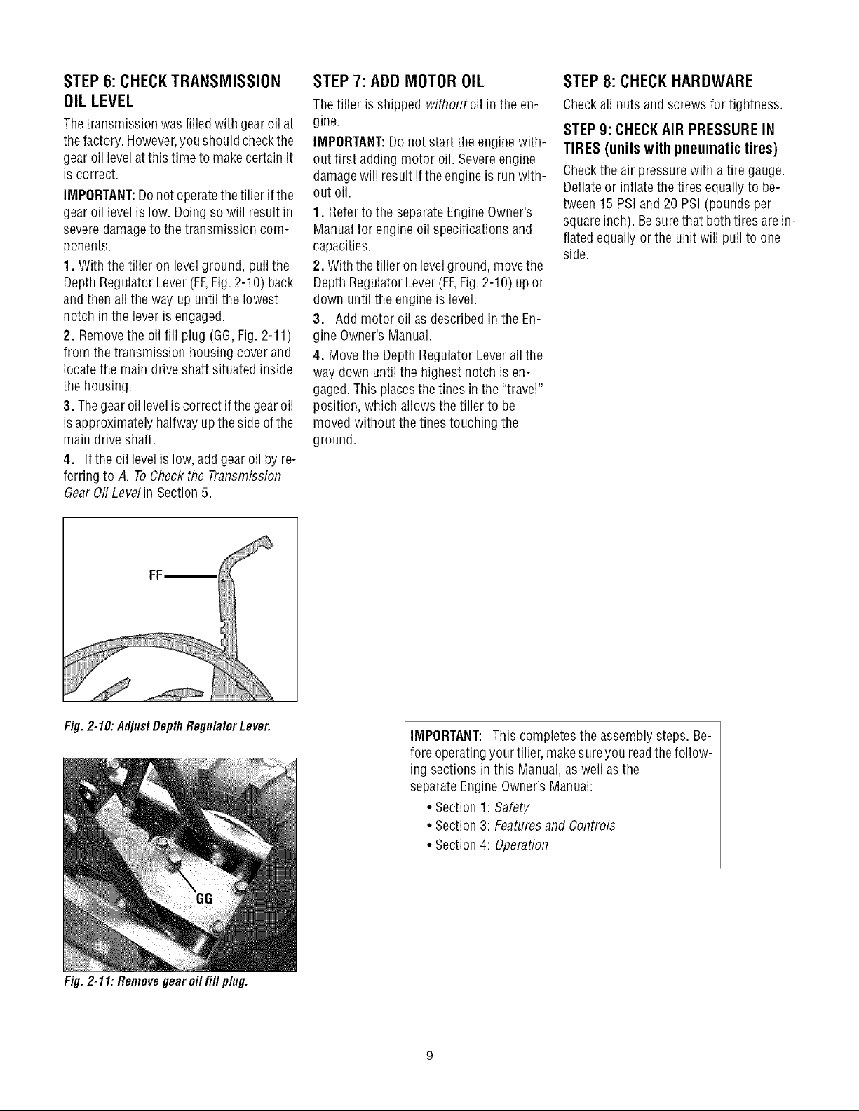
1. With the tiller on levelground, pull the
Depth RegulatorLever(FF,Fig. 2-10) back
andthen all theway up until the lowest
notch inthe lever isengaged.
2. Removethe oil fill plug (GG,Fig. 2-11)
from the transmission housing cover and
locatethe main drive shaft situated inside
the housing.
3. Thegear oil leveliscorrect if the gearoil
isapproximately halfway upthe sideofthe
main driveshaft.
4. Ifthe oil levelislow, addgear oil by re-
ferring to A, ToCheckthe Transmission
GearOil Level in Section5.
I El."/: AUU IVlUI UH UIL
Thetiller isshipped withoutoil in the en-
gine.
IMPORTANT:Donot start the engine with-
out first adding motor oil. Severeengine
damagewill resultif the engineis run with-
out oil.
1. Referto the separateEngineOwner's
Manualfor engine oil specifications and
capacities.
2. With thetiller on levelground, movethe
Depth RegulatorLever(FF,Fig.2-10) up or
down until the engine is level.
3. Addmotor oil as describedin the En-
gine Owner's Manual.
4. Movethe DepthRegulator Leverall the
way down untilthe highest notch is en-
gaged.This placesthe tines in the"travel"
position, which allows the tiller to be
moved without thetines touching the
ground.
_ I L:I."8: L;Ht:L;KHAHUWAHt:
Checkall nuts and screws for tightness.
STEP 9: CHECKAIR PRESSURE IN
TIRES (units with pneumatic tires)
Checkthe air pressurewith atire gauge.
Deflateor inflatethe tires equally to be-
tween 15 PSiand 20 PSi (pounds per
squareinch). Besurethat both tires arein-
flated equally orthe unit will pull to one
side.
Fig. 2-10: AdjustDepth Regu/atorLever.
Fig. 2-11: Removegear oil fill plug.
IMPORTANT: This completesthe assembly steps. Be-
fore operatingyour tiller, makesureyou readthefollow-
ing sectionsin this Manual,as well as the
separateEngineOwner'sManual:
• Section 1: Safety
• Section 3: Featuresand Controls
• Section 4: Operation
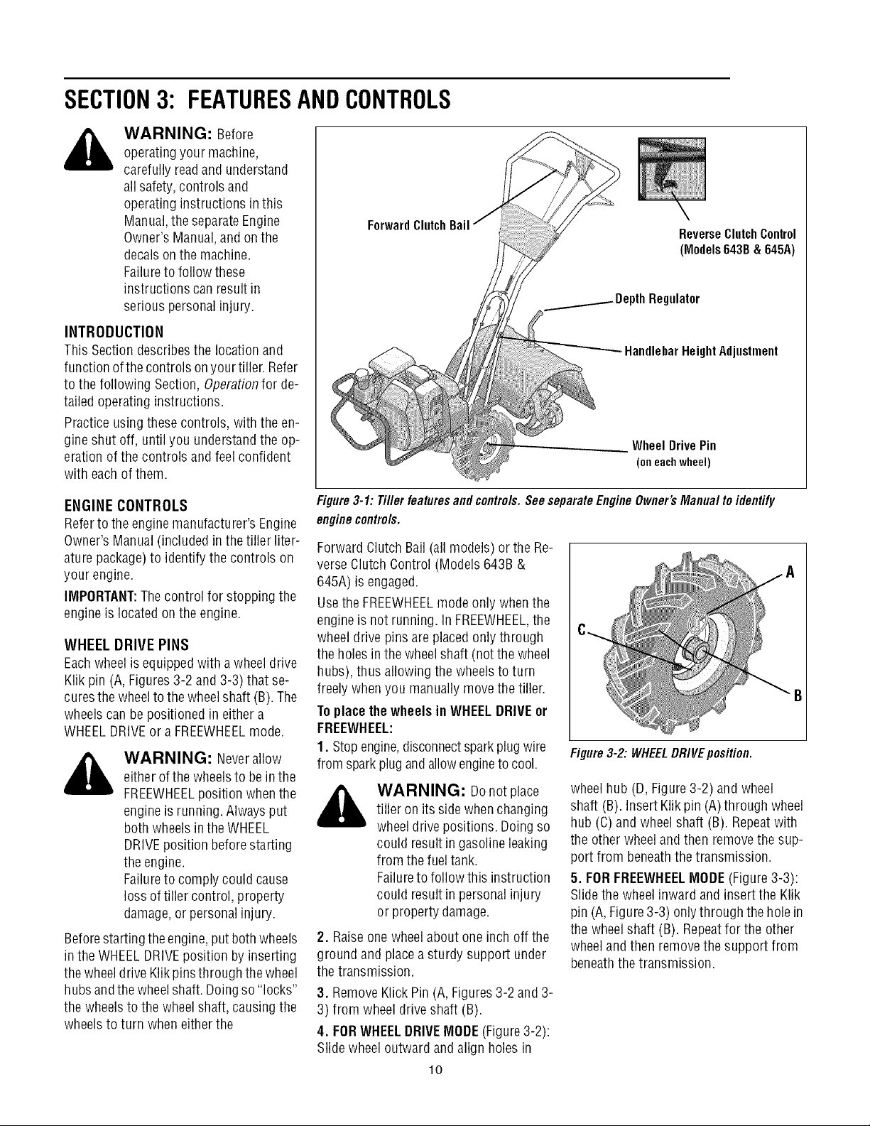
SECTION3: FEATURESANDCONTROLS
_ ARNING: Before
operatingyour machine,
carefully readand understand
all safety, controls and
operating instructions in this
Manual,the separateEngine
Owner's Manual,and on the
decalson the machine.
Failureto follow these
instructions can result in
serious personal injury.
INTRODUCTION
This Section describesthe location and
function ofthecontrols onyourtiller. Refer
to the following Section, Operationfor de-
tailed operatinginstructions.
Practice usingthese controls, with the en-
gine shut off, untilyou understandthe op-
eration ofthe controls andfeelconfident
with eachof them.
ForwardClutch
ReverseClutchControl
(Models643B&645A)
Regulator
HeightAdjustment
Wheel Drive Pin
(oneachwheel)
ENGINE CONTROLS
Referto the enginemanufacturer'sEngine
Owner'sManual (included in the tiller liter-
aturepackage)to identify the controls on
your engine.
IMPORTANT:Thecontrol for stopping the
engine is locatedonthe engine.
WHEEL DRIVE PINS
Eachwheel is equippedwith a wheel drive
Klik pin (A, Figures3-2 and 3-3) that se-
curesthe wheelto the wheel shaft (B).The
wheelscan be positioned in either a
WHEELDRIVEor a FREEWHEELmode.
_ WARNING: Neverallow
either ofthewheelsto bein the
FREEWHEELposition whenthe
engineis running. Alwaysput
both wheelsin the WHEEL
DRIVEposition beforestarting
the engine.
Failureto comply could cause
loss of tiller control, property
damage,or personalinjury.
Beforestarting the engine,put both wheels
in the WHEELDRIVEposition byinserting
the wheeldriveKlikpinsthrough the wheel
hubsandthewheelshaft. Doingso "locks"
the wheels to the wheelshaft, causing the
wheelsto turn when eitherthe
Figure3-1: Tiller features and controls.See separateEngine Owner's Manual toidentify
enginecontrols.
Forward Clutch Bail (all models) or the Re-
verse Clutch Control (Models 643B &
645A) is engaged.
Usethe FREEWHEELmode only whenthe
engineis not running. InFREEWHEEL,the
wheeldrive pinsare placedonly through
the holes in thewheelshaft (not the wheel
hubs), thus allowing the wheelsto turn
freely when you manually movethe tiller.
Toplacethe wheels in WHEELDRIVEor
FREEWHEEL:
1. Stopengine,disconnectsparkplug wire
from sparkplug andallowengineto cool.
_ WARNING: Donotplace
tiller on its sidewhen changing
wheeldrivepositions. Doingso
could result ingasoline leaking
from the fuel tank.
Failureto follow this instruction
could result in personal injury
or propertydamage.
2. Raiseone wheelabout one inch off the
ground andplaceasturdy support under
the transmission.
3. RemoveKlick Pin (A, Figures3-2 and 3-
3) from wheel driveshaft (B).
4. FORWHEELDRIVEMODE(Figure3-2):
Slide wheel outward andalign holes in
"B
Figure3-2: WHEELDRIVEposition.
wheelhub (D,Figure 3-2) and wheel
shaft (B). Insert Klik pin(A) through wheel
hub (C)and wheelshaft (B). Repeatwith
the other wheelandthen removethe sup-
port from beneaththe transmission.
5. FORFREEWHEELMODE(Figure 3-3):
Slide the wheelinward and insert the Klik
pin (A,Figure3-3) onlythrough thehole in
the wheelshaft (B). Repeatfor the other
wheeland then removethe support from
beneaththe transmission.
lO
 Loading...