


®
Operator’s Manual
AF720
SAVE THESE INSTRUCTIONS
For service call 1-800-345-8746, or 1-800-668-1238 in Canada to obtain a list of authorized service dealers near you. For more details about your unit, visit our website at www.trimmerplus.com.
If you have difficulty assembling this product or have any questions regarding the controls, operation or maintenance of this unit, please call the Customer Support Department.
DO NOT RETURN THE UNIT TO THE RETAILER. PROOF OF PURCHASE WILL BE REQUIRED FOR WARRANTY SERVICE.
Service on this unit both within and after the warranty period should be performed only by an authorized and approved service dealer.
All information, illustrations, and specifications in this manual are based on the latest product information available at the time of printing. We reserve the right to make changes at any time without notice.
Copyright© 2011 MTD SOUTHWEST INC, All Rights Reserved.
TABLE OF CONTENTS
Service Information . . . . . . . . . . . . . . . . . . . . . . . . . . . . . . . . . . . . .1
Rules for Safe Operation . . . . . . . . . . . . . . . . . . . . . . . . . . . . . . . . .2
Know Your Unit . . . . . . . . . . . . . . . . . . . . . . . . . . . . . . . . . . . . . . . .3
Assembly Instructions . . . . . . . . . . . . . . . . . . . . . . . . . . . . . . . . . . .3
Operating Instructions . . . . . . . . . . . . . . . . . . . . . . . . . . . . . . . . . . .4
Maintenance & Repair Instructions . . . . . . . . . . . . . . . . . . . . . . . . .4
Cleaning and Storage . . . . . . . . . . . . . . . . . . . . . . . . . . . . . . . . . . .4
Specifications . . . . . . . . . . . . . . . . . . . . . . . . . . . . . . . . . . . . . . . . .4
Warranty Information . . . . . . . . . . . . . . . . . . . . . . . . . . . . . . . . . . .16
PART NO. 769-06462 P00 |
(01/11) |
RULES FOR SAFE OPERATION
The purpose of safety symbols is to attract your attention to possible dangers. The safety symbols, and their explanations, deserve your careful attention and understanding. The safety warnings do not by themselves eliminate any danger. The instructions or warnings they give are not substitutes for proper accident prevention measures.
SYMBOL MEANING
SAFETY ALERT: Indicates danger, warning or caution. Attention is required in order to avoid serious personal injury. May be used in conjunction with other symbols or pictographs.
NOTE: Advises you of information or instructions vital to the operation or maintenance of the equipment.
WHILE OPERATING
•Keep bystanders, especially children and pets, at least 50 ft (15 m) away.
•Wear safety glasses or goggles that are marked as meeting ANSI Z87.1 standards, and ear/hearing protection when operating this unit. Wear a face or dust mask if the operation is dusty.
•Wear heavy, long pants, boots, gloves and a long sleeve shirt. Do not wear loose clothing, jewelry, short pants, sandals or go barefoot. Secure hair above shoulder level.
•Use the unit only in daylight or good artificial light.
•Use the right tool. Only use this tool for the purpose intended.
•Check all cutting blades for defects prior to use. Blades may become worn or cracked over time. If needing to replace one, it is highly recommended to replace all 4.
•Do not force unit. It will do the job better and with less likelihood of injury at a rate for which it was designed.
DANGER: Failure to obey a safety warning will result in serious injury to yourself or to others. Always follow the safety precautions to reduce the risk of fire, electric shock and personal injury.
WARNING: Failure to obey a safety warning can result in injury to yourself and others. Always follow the safety precautions to reduce the risk of fire, electric shock and personal injury.
CAUTION: Failure to obey a safety warning may result in property damage or personal injury to yourself or to others. Always follow the safety precautions to reduce the risk of fire, electric shock and personal injury.
Read the Operator’s Manual and follow all warnings and safety instructions. Failure to do so can result in serious injury to the operator and/or bystanders.
FOR QUESTIONS, CALL 1-800-345-8746 IN U.S. OR 1-800-668-1238 in CANADA
• IMPORTANT SAFETY INSTRUCTIONS •
READ ALL INSTRUCTIONS BEFORE OPERATING
WARNING: When using the unit, you must follow the safety rules. Please read these instructions before operating the unit in order to ensure the safety of the operator and any bystanders. Please keep these instructions for later use.
•Carefully read and understand the operator's manual of the unit that powers this attachment.
•Read this operating instruction manual carefully. Be thoroughly familiar with the controls and the proper use of the equipment. Know how to stop the unit and disengage the controls quickly.
•Do not operate this unit when tired, ill, or under the influence of alcohol, drugs, or medication.
•Never allow children to operate the equipment. Never allow adults unfamiliar with the instructions to use the unit. Never allow adults to operate the equipment without proper instruction.
•All guards and safety attachments must be installed properly before operating the unit.
•Inspect the unit before use.
•Clear the area before each use. Remove all objects such as rocks, broken glass, nails, wire, or string which can be thrown or become entangled in the attachment.
•Use only AERO-FLEX® replacement blades. Never use metalreinforced line, wire, or rope, etc. These can break off and become a dangerous projectile.
•This unit was not designed to be used as a brushcutter. Do not attach or operate this unit with any type of brushcutting blade or brushcutting attachment.
•Do not overreach, take extra care when working on steep slopes or inclines. Always keep proper footing and balance.
•Always hold the unit with both hands when operating. Keep a firm grip on both the front and rear handle or grips.
•Keep hands, face, and feet at a distance from all moving parts. Do not touch or try to stop the cutting attachment when it is rotating. Do not operate without guards in place.
•Do not operate the engine faster than the speed needed to do the job. Do not run the engine at high speed when not in use.
•Always stop the engine/motor when operation is delayed or when walking from one location to another.
.• If you strike or become entangled with a foreign object, stop the engine/motor immediately and check for damage. Have any damage repaired before attempting further operations.
•Stop the unit IMMEDIATELY if you feel excessive vibration. Vibration is a sign of trouble. Inspect thoroughly for loose nuts, bolts or damage before continuing. Repair or replace affected parts as necessary.
•Stop and switch the unit to off for maintenance, repair, or for changing add-ons or other attachments. The unit must be stopped and the cutting head no longer turning to avoid injury.
•Use only original equipment manufacturer replacement parts and accessories for this unit. These are available from your authorized service dealer. Use of any unauthorized parts or accessories could lead to serious injury to the user, or damage to the unit, and void your warranty.
•To reduce the danger of thrown objects or debris, run the unit at lower speeds (partial throttle) for most trimming operations. Heavier vegetation cutting may require additional power and speed.
MAINTENANCE AND STORAGE
•Allow the unit to cool before storing or transporting. Be sure to secure the unit while transporting.
•Store the unit in a locked up and dry or high and dry place to prevent unauthorized use or damage, out of the reach of children.
•Never douse or squirt the unit with water or any other liquid. Keep handles dry, clean and free from debris. Clean unit and labels with a damp sponge. Clean after each use.
•Keep these instructions. Refer to them often and use them to instruct other users. If you loan someone this unit, also loan them these instructions.
•Only qualified personnel should perform any repairs or maintenance procedures that are not described in this manual.
•Check all bolts and nuts at frequent intervals for proper tightness to be sure the equipment is in safe working condition.
•Inside a building, store the unit away from ignition sources. Allow the engine to cool before storing in any enclosure.
•Always refer to the Operator’s Manual instructions for important details if the unit is to be stored for an extended period.
•Do not attempt to repair the machine unless you have the proper tools, and instructions for disassembly and repair of the machine.
SAVE THESE INSTRUCTIONS
2

RULES FOR SAFE OPERATION
This operator's manual describes safety and international symbols and pictographs that may appear on this product. Read the operator's manual for complete safety, assembly, operating and maintenance and repair information.
SYMBOL MEANING
•SAFETY ALERT SYMBOL
Indicates danger, warning or caution. May be used in conjunction with other symbols or pictographs.
•WARNING - READ OPERATOR'S MANUAL
Read the operator’s manual(s) and follow all warnings and safety instructions. Failure to do so can result in serious injury to the operator and/or bystanders.
•WEAR EYE AND HEARING PROTECTION
WARNING: Thrown objects and loud noise can cause severe eye injury and hearing loss. Wear eye protection meeting ANSI Z87.1-1989 standards and ear protection when operating this unit. Use a full face shield when needed.
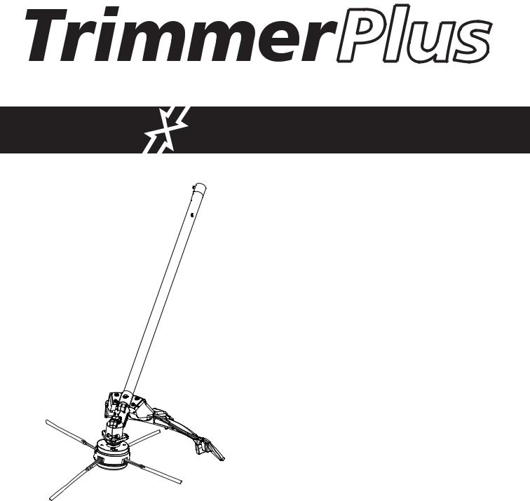
KNOW YOUR UNIT
Applications:
•Cutting grass and light weeds.
•Edging
•Decorative trimming around trees, fences, etc.
Tools Required:
•Phillips Screwdriver
Shaft Housing
Cutting Attachment
Shield
Cutting
Attachment
Cap Tab
Cutting Blades
SYMBOL MEANING
• THROWN OBJECTS AND ROTATING CUTTER CAN CAUSE SEVERE INJURY
WARNING: Small objects can be propelled at high speed, causing injury. Keep away from the rotating rotor.
• HOT SURFACE WARNING
Do not touch a hot surface. You may get burned. These parts get extremely hot from operation. They remain hot for a short time after the unit is turned off.
• KEEP BYSTANDERS AWAY
WARNING: Keep all bystanders, especially children and pets, at least 50 feet (15 m.) from the operating area.
ASSEMBLY INSTRUCTIONS
INSTALL CUTTING ATTACHMENT SHIELD
WARNING: To prevent serious personal injury, never operate the trimmer without the cutting attachment shield in place.
Use the following instructions if the cutting attachment shield on your unit is not installed. Use only the instructions that apply to the type of shaft and shield that your unit is equipped with.
1.Place the cutting head shield onto the guard mount bracket, making sure to align the holes on the shield with the holes in the guard mount bracket. (Fig. 1)
|
Screw (4) |
Cutting |
Guard |
Head |
Mount |
Shield |
Bracket |
Fig. 1
2.Take the 4 shield screws and screw each one into the shield until finger tight.
3.Using a Phillips screw driver, tighten the screws equally until the shield is firmly in place.
ASSEMBLING THE COUPLER
|
WARNING: Prior to operation, read and |
Coupler |
Release |
|
|
Button |
|
|
understand the operator’s manual for unit to be |
|
|
|
|
|
|
|
used with this add-on. |
|
|
The Trimmer Plus add-on may be mounted to different power |
|
|
|
tools. The instruction manuals for the basic power tool and the |
|
|
|
attachment contain the information necessary for operation of the |
|
|
|
power tool combination. Therefore, always read BOTH instruction |
|
|
|
manuals before using the power tool for the first time. Keep the |
|
Guide Recess |
|
manuals in a safe place for future reference. |
|
Fig. 2 |
|
NOTE: |
To make installing or removing the add-on easier, |
|
|
|
|
||
place the unit on the ground or on a work bench.
Removing the Add-On
WARNING: To avoid serious personal injury and damage to the unit, shut the unit off before removing or installing add-ons.
1.Turn the knob counterclockwise to loosen (Fig. 4).
2.Press and hold the release button (Fig. 2).
3.While firmly holding the upper shaft housing, pull the addon out of the coupler (Fig. 3).
Installing the Add-On
CAUTION: Lock the release button in the primary hole and securely tighten the knob before operating this unit.
1.Remove the hanger or shipping cap from the top of the shaft housing.
2.Turn knob counterclockwise to loosen (Fig. 4).
3.While firmly holding the add-on, push it straight into the coupler (Fig. 3).
NOTE: Aligning the release button with the guide recess will help installation (Fig. 2).
Primary Hole
Upper Shaft |
|
Lower Shaft |
Housing |
|
Housing |
|
|
|
|
Fig. 3 |
|
90˚ Edging Hole |
|
|
|
|
|
|
|
|
(Trimmer Only) |
|
|
Knob
Fig. 4
4.Turn the knob clockwise to tighten (Fig. 4).
The add-on should be installed with the release button in the primary hole.
CAUTION: Add-ons are to be used in the primary hole only. Using the wrong hole could lead to personal injury or damage to the unit.
Check Flex Shaft Engagement Prior to Using
1.Start the unit.
2.Briefly engage and release the trigger.
3.Check that add-on is operating.
4.If the add-on is not operating, remove add-on and repeat steps for installing the add-on.
5.Recheck operation of add-on attachment.
NOTE: The blades are NOT installed on this product when first removed from packaging. Refer to Trimmer Blade Replacement/ Installation section of this manual.
3

OPERATING INSTRUCTIONS
HOLDING THE TRIMMER
WARNING: Always wear eye, hearing, foot and body protection to reduce the risk of injury when operating this unit.
Before operating the unit, stand in the operating position (Fig. 5). Check for the following:
• The operator is wearing eye protection and proper clothing
• With a slightly-bent right arm, the operator’s right hand is |
|
holding the shaft grip |
Fig. 5 |
•The operator’s left arm is straight, the left hand holding the handle
•The unit is at waist level
WARNING: If a blade breakage occurs, replace all blades immediately as the unit may become unstable and hard to control. Resulting in serious personal injury.
Some blade breakage may occur from:
•Entanglement with foreign matter
•Normal blade fatigue
•Attempting to cut thick or stalky weeds
•Forcing the blades into objects such as walls or fence posts
NOTE: Change all 4 blades once cutting performance becomes poor.
TIPS FOR BEST TRIMMING RESULTS
•For best trimming results, it is recommended to use a combination of orange and yellow blades for the Vegetation Tasks with the corresponding throttle speeds listed below:
Vegetation Task |
Blade Color |
Low Throttle |
Medium Throttle |
High Throttle |
|
|
|
|
|
Edging |
2 + 2 Mix |
Yes |
Yes |
No |
|
|
|
|
|
Trimming |
2 + 2 Mix |
No |
Yes |
Yes |
|
|
|
|
|
Trimming against fences |
2 + 2 Mix |
Yes |
Yes |
No |
|
|
|
|
|
•Do not force the cutting attachment. Allow the tip of the blade to do the cutting, especially along walls. Cutting with more than the tip will reduce cutting efficiency and may overload the engine.
•Cut grass over 8 inches (200 mm) by working from top to bottom in small increments to avoid premature line wear or engine drag.
•Slowly move the trimmer into and out of the cutting area at the desired height. Move either in a forward-backward or side-to-side motion. Cutting shorter lengths produces the best results.
•Trim only when grass and weeds are dry.
•The life of your cutting line is dependent upon:
• Proper adherence of explained trimming techniques
• What vegetation is cut
• Where vegetation is cut
For example, the blade may wear faster when trimming against a foundation wall as opposed to trimming around a tree.
DECORATIVE TRIMMING
Decorative trimming is accomplished by removing all vegetation around trees, posts, fences and more.
Rotate the whole unit so that the cutting attachment is at a 30°
angle to the ground (Fig. 6). |
|
Fig. 6 |
|
||
|
|
STARTING THE UNIT
STARTING INSTRUCTIONS
For specific starting instructions, see the appropriate section of your powerhead manual. Proper starting methods reduce the risk of injury.
WARNING: To reduce the risk of fire and burn injuries, start the engine at least 30 ft. (9.1 m) from the fueling spot, outdoors only.
MAINTENANCE AND REPAIR INSTRUCTIONS
TRIMMER BLADE REPLACEMENT/ INSTALLATION
WARNING: Never use metal-reinforced line, wire, chain, or rope. These can break off and become dangerous projectiles.
Always use original equipment manufacturer replacement blades. Blades other than those specified may make the engine overheat or fail. 
To removing the trimming blades:
1.Remove the cutting head cap by pressing in on both cap tabs and then pulling down on the cap. (Fig. 7)
2.Turn the cutting head over and grab an individual blade near the cutting head and wiggle it up and down until blade comes loose. (Fig. 8)
3. Repeat step 2 until all blades are removed. To install the trimming blades:
4. Take the new blade so that the loop at the end is facing away and to the right. (Fig. 8)
5.Place the loop onto the peg and adjust it so that it fits into the slot on the cutting head. (Fig. 8)
6.Press down on the loop end of the blade till it is securely in place.
7.Repeat steps 4 thru 6 until all 4 blades are in place. (Fig. 8)
Cutting
Head


 Cap Tab
Fig. 7
Peg
Cutting
Blade
Blade Slot
Fig. 8
NOTE: Make sure to place the blades so that they alternate in color. Never place 2 yellow or 2 orange side by side.
WARNING: Always install all four blades, 2 yellow and 2 orange. NEVER install 1, 2 or 3 blades as this will make the trimming unit unstable and hard to control. Which could result in serious personal injury.
8.Replace the cutting head cap, making sure to align the cap tabs with the cutting head tab slots. (Fig. 9)
9.Once the cap is in place, press down until the tabs snap and lock into place.
CLEANING
Cap
Cap Tab
Cutting Head
Tab Slots
Fig. 9
Use a small brush to clean off the outside of the unit.
Do not use strong detergents. Household cleaners that contain aromatic oils such as pine and lemon, and solvents such as kerosene, can damage plastic housing or handle. Wipe off any moisture with a soft cloth.
STORAGE
•Check unit before storage to be sure the equipment is in safe working condition.
•Stop the engine or motor.
•Store the unit indoors, in a dry and locked place, out of the reach of children.
•Maintain or replace safety and instruction labels, as necessary.
•Store spare blades in a bag with a small amount of water. This will prevent the blades from drying out and keep them flexible.
TRANSPORTING
•Allow the unit to cool before transporting.
•Secure the unit while transporting.
ACCESSORIES
Cutting Blades . . . . . . . . . . . . . . . . . . . . . . . . . . . . . . . . . . . . . . . . . . . . . . . . . . . . . . . . . . . . 49UAFRLK953
SPECIFICATIONS
MACH 4® ADD-ON
Approximate Operating Weight of Attachment . . . . . . . . . . . . . . . . . . . . . . . . . . . . . . . . . . 3.3 lbs. (1.5 kg) Cutting Width . . . . . . . . . . . . . . . . . . . . . . . . . . . . . . . . . . . . . . . . . . . . . . . . . . . . . . . . . 14 inches (35.6 cm)
4
®
Manuel de L’utilisateur
AF720
CONSERVER CES INSTRUCTIONS
Obtenez la liste des concessionnaires agréés appelez le 1-800-345-8746 aux États-Unis ou le 1-800-668-1238 au Canada. Pour de plus amples informations à propos de votre appareil, visitez www.trimmerplus.com.
Si vous éprouvez des difficultés à assembler ce produit ou si vous avez des questions sur les commandes, l'utilisation ou l'entretien de cet appareil, veuillez contacter le service à la clientèle.
NE RETOURNEZ PAS L'APPAREIL AU DÉTAILLANT CHEZ QUI VOUS L'AVEZ ACHETÉ. TOUT SERVICE SOUS GARANTIE NÉCESSITE UNE PREUVE D'ACHAT.
Tout entretien effectué sur cet appareil pendant et après la période de garantie doit être fait par un concessionnaire agréé uniquement.
Toutes les informations, illustrations et spécifications contenues dans ce manuel tiennent compte des dernières informations techniques disponibles au moment de mettre sous presse. Nous nous réservons le droit d'y apporter des modifications à tout moment, sans préavis.
Copyright© 2011 MTD SOUTHWEST INC, All Rights Reserved.
TABLE DES MATIÈRES
Service technique . . . . . . . . . . . . . . . . . . . . . . . . . . . . . . . . . . . . . .5
Consignes de sécurité . . . . . . . . . . . . . . . . . . . . . . . . . . . . . . . . . .6
Familiarisez-vous avec votre appareil . . . . . . . . . . . . . . . . . . . . . . .7
Instructions de montage . . . . . . . . . . . . . . . . . . . . . . . . . . . . . . . . .7
Mode d'emploi . . . . . . . . . . . . . . . . . . . . . . . . . . . . . . . . . . . . . . . .8
Entretien et réparations . . . . . . . . . . . . . . . . . . . . . . . . . . . . . . . . . .8
Nettoyage et entreposage . . . . . . . . . . . . . . . . . . . . . . . . . . . . . . . .8
Caractéristiques . . . . . . . . . . . . . . . . . . . . . . . . . . . . . . . . . . . . . . .8
Garantie . . . . . . . . . . . . . . . . . . . . . . . . . . . . . . . . . . . . . . . . . . . . .16
PART NO. 769-06462 P00 |
(01/11) |
 Loading...