


Owner’s Manual / Manual del Propietario
Portable Generator / Generador Portátil
Model / Modelo 01925
IMPORTANT: READ SAFETY RULES AND INSTRUCTIONS CAREFULLY
IMPORTANTE: LEYO LA SEGURIDAD LAS ORDENES Y LAS INSTRUCCIONES DETENIDAMENTE
Questions? Preguntas?
Helpline - 1-888-611-6708 M-F 8-5 CT
Troy-Bilt® is a registered trademark of Troy-Bilt, LLC and is used under license to Briggs & Stratton Power Products. Troy-Bilt® es una marca registrada de Troy-Bilt, LLC y se usa abajo licencia a Briggs & Stratton Power Products.
BRIGGS & STRATTON POWER PRODUCTS GROUP, LLC
JEFFERSON,WISCONSIN, U.S.A.
Printed in USA |
Manual No. 192472GS Revision 6 (03/23/2004) |
Section |
Safety Rules |
|
1
TABLE OF CONTENTS
Safety Rules. . . . . . . . . . . . . . . . . . . . . . . . . . . . . . . . . . . . 2-4
Know Your Generator . . . . . . . . . . . . . . . . . . . . . . . . . . . . . 5
Assembly. . . . . . . . . . . . . . . . . . . . . . . . . . . . . . . . . . . . . . 6-7
Operation . . . . . . . . . . . . . . . . . . . . . . . . . . . . . . . . . . . . 8-13
Maintenance . . . . . . . . . . . . . . . . . . . . . . . . . . . . . . . . . 14-15
Storage . . . . . . . . . . . . . . . . . . . . . . . . . . . . . . . . . . . . . . . . 16
Troubleshooting . . . . . . . . . . . . . . . . . . . . . . . . . . . . . . . . . 17
Schematic/Wiring Diagram . . . . . . . . . . . . . . . . . . . . . 18-19
Replacement Parts . . . . . . . . . . . . . . . . . . . . . . . . . . . . 20-24
Notes . . . . . . . . . . . . . . . . . . . . . . . . . . . . . . . . . . . . . . . . . 25
Warranty. . . . . . . . . . . . . . . . . . . . . . . . . . . . . . . . . Last Page
EQUIPMENT
DESCRIPTION
Read this manual carefully and become familiar with your generator. Know its applications, its limitations and any hazards involved.
This manual describes an engine–driven, revolving field, alternating current (AC) generator designed to supply electrical power for operating compatible electrical lighting, appliances, tools and motor loads.The generator’s revolving field is driven at about 3,600 rpm by a single-cylinder engine.
CAUTION! DO NOT exceed the generator’s wattage/amperage capacity. See “Don’t Overload Generator” on page 13.
Every effort has been made to ensure that information in this manual is accurate and current. However, we reserve the right to change, alter or otherwise improve the product and this document at any time without prior notice.
The Emission Control System for this generator is warranted for standards set by the Environmental Protection Agency. For warranty information refer to the engine owner’s manual.
In the State of California a spark arrester is required by law (Section 4442 of the California Public Resources Code). Other states may have similar laws. Federal laws apply on federal lands. If you equip the muffler with a spark arrester, it must be maintained in effective working order.
SAFETY RULES
This is the safety alert symbol. It is used to alert you to potential personal injury hazards. Obey all safety messages that follow this symbol to avoid possible injury or death.
The safety alert symbol ( ) is used with a signal word (DANGER, CAUTION,WARNING), a pictorial and/or a safety message to alert you to hazards. DANGER indicates a hazard which, if not avoided, will result in death or serious injury. WARNING indicates a hazard which, if not avoided, could result in death or serious injury. CAUTION indicates a hazard which, if not avoided, might result in minor or moderate injury. CAUTION, when used without the alert symbol, indicates a situation that could result in equipment damage. Follow safety messages to avoid or reduce the risk of injury or death.
 WARNING
The engine exhaust from this product contains chemicals known to the State of California to cause cancer, birth defects, or other reproductive harm.
Hazard Symbols and Meanings
Electrocution |
Electrical Shock |
Electrical Shock |
Toxic Fumes |
Explosion |
Fire |
Explosive Pressure |
Chemical Burn |
Hot Surface |
2
Section 1: Safety Rules
 DANGER
Running generator gives off carbon monoxide, an odorless, colorless, poison gas.
Breathing carbon monoxide will cause nausea, fainting or death.
•Operate generator ONLY outdoors.
•Keep at least 2 feet of clearance on all sides of generator for adequate ventilation.
•DO NOT operate generator inside any building or enclosure, including the generator compartment of a recreational vehicle (RV).
 DANGER
Generator produces powerful voltage.
Failure to isolate generator from power utility can result in death or injury to electric utility workers due to backfeed of electrical energy.
•When using generator for backup power, notify utility company. Use approved transfer equipment to isolate generator from electric utility.
•Use a ground circuit fault interrupter (GFCI) in any damp or
highly conductive area, such as metal decking or steel work.
•DO NOT touch bare wires or receptacles.
•DO NOT use generator with electrical cords which are worn, frayed, bare or otherwise damaged.
•DO NOT operate generator in the rain.
•DO NOT handle generator or electrical cords while standing
in water, while barefoot, or while hands or feet are wet.
•DO NOT allow unqualified persons or children to operate or service generator.
 DANGER
Storage batteries give off explosive hydrogen gas during recharging.
Hydrogen gas stays around battery for a long time after battery has been charged.
Slightest spark will ignite hydrogen and cause explosion.
You can be blinded or severely injured.
Battery electrolyte fluid contains acid and is extremely caustic.
Contact with battery fluid will cause severe chemical burns.
•DO NOT allow any open flame, spark, heat, or lit cigarette during and for several minutes after charging a battery.
•Wear protective goggles, rubber apron, and rubber gloves.
 WARNING
Fuel and its vapors are extremely flammable and explosive.
Fire or explosion can cause severe burns or death.
WHEN ADDING FUEL
• Turn generator OFF and let it cool at least 2 minutes before removing gas cap. Loosen cap slowly to relieve pressure in tank.
•Fill fuel tank outdoors.
•DO NOT overfill tank.Allow space for fuel expansion.
•Keep fuel away from sparks, open flames, pilot lights, heat, and other ignition sources.
•DO NOT light a cigarette or smoke.
WHEN OPERATING EQUIPMENT
•DO NOT tip engine or equipment at angle which causes fuel to spill.
•This generator is not for use in mobile equipment or marine applications.
WHEN TRANSPORTING OR REPAIRING EQUIPMENT
•Transport/repair with fuel tank EMPTY.
•Disconnect spark plug wire.
WHEN STORING FUEL OR EQUIPMENT WITH FUEL IN TANK
•Store away from furnaces, stoves, water heaters, clothes dryers or other appliances that have pilot light or other ignition source because they can ignite fuel vapors.
 WARNING
•This generator does not meet U. S. Coast Guard Regulation 33CFR-183 and should not be used on marine applications.
•Failure to use the appropriate U. S. Coast Guard approved generator could result in bodily injury and/or property damage.
3
Section 1: Safety Rules
 WARNING
Unintentional sparking can result in fire or electric shock.
WHEN ADJUSTING OR MAKING REPAIRS TO YOUR GENERATOR
•Disconnect the spark plug wire from the spark plug and place the wire where it cannot contact spark plug.
 WARNING
Running engines produce heat.Temperature of muffler and nearby areas can reach or exceed 150°F (65°C).
Severe burns can occur on contact.
•DO NOT touch hot surfaces.
•Allow equipment to cool before touching.
 CAUTION
Excessively high operating speeds increase risk of injury and damage to generator.
Excessively low speeds impose a heavy load.
•DO NOT tamper with governed speed. Generator supplies correct rated frequency and voltage when running at governed speed.
•DO NOT modify generator in any way.
CAUTION
Exceeding generator’s wattage/amperage capacity can damage generator and/or electrical devices connected to it.
•See “Don’t Overload Generator” on page 13.
•Start generator and let engine stabilize before connecting electrical loads.
•Connect electrical loads in OFF position, then turn ON for operation.
•Turn electrical loads OFF and disconnect from generator before stopping generator.
CAUTION
Improper treatment of generator can damage it and shorten its life.
•Use generator only for intended uses.
•If you have questions about intended use, ask dealer or call 1-888-611-6708.
•Operate generator only on level surfaces.
•DO NOT expose generator to excessive moisture, dust, dirt, or corrosive vapors.
•DO NOT insert any objects through cooling slots.
•If connected devices overheat, turn them off and disconnect them from generator.
•Shut off generator if:
-electrical output is lost;
-equipment sparks, smokes, or emits flames; -unit vibrates excessively.
4
Features and Controls Section
2
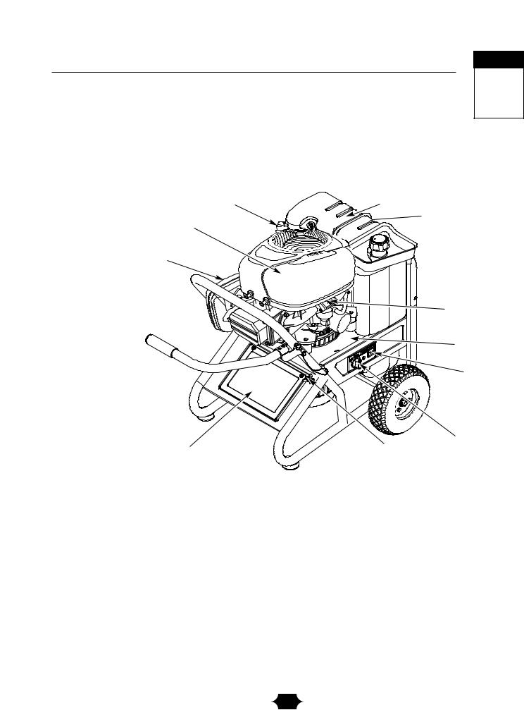
KNOW YOUR GENERATOR
Read this owner’s manual and safety rules before operating your generator.
Compare this illustration with your generator to familiarize yourself with the locations of various controls and adjustments. Save this manual for future reference.
Oil Fill Cap
Air Cleaner
Spark Arrester Muffler
Battery
12 Volt DC Receptacle — Use this receptacle with battery charge cables to charge a 12 Volt battery.
120Volt AC, 20 Amp Duplex Receptacles — May be used to supply electrical power for the operation of 120Volt AC, 20 Amp, single phase, 60 Hz electrical lighting, appliance, tool and motor loads.
120/240 Volt AC, 30 Amp Locking Receptacle — May be used to supply electrical power for the operation of 120 and/or 240 Volt AC, 30 Amp, single phase, 60 Hz electrical lighting, appliance, tool and motor loads.
Air Cleaner — Uses a dry type filter element and foam pre–cleaner to limit the amount of dirt and dust sucked into the engine.
Battery — Located behind plastic cover. 12 Volt DC sealed battery provides power to start the engine.
Choke Lever — Used when starting a cold engine.
5
Section Assembly
3
ASSEMBLY
Your generator requires attachment of the negative battery cable and is ready for use after it has been properly serviced with the recommended oil and fuel.
If you have any problems with the assembly of your generator, please call the generator helpline at 1-888-611-6708.
Remove Generator From Carton
1.Set carton on a rigid flat surface with “This Side Up” arrows pointing upward.
2.Carefully open top flaps of shipping carton.
3.Cut down corners of carton from top to bottom and lay that side of carton down flat.
4.Remove all packing material, carton fillers, etc.
5.Roll generator out of shipping carton.
Attach Negative Battery Cable
The sealed battery on the generator is fully charged and pre–installed except for the negative (black) battery cable.
You will need a 1/2” or 13 mm wrench to install the negative battery cable.
To install:
1.Cut off tie wrap securing loose end of negative (black) cable.
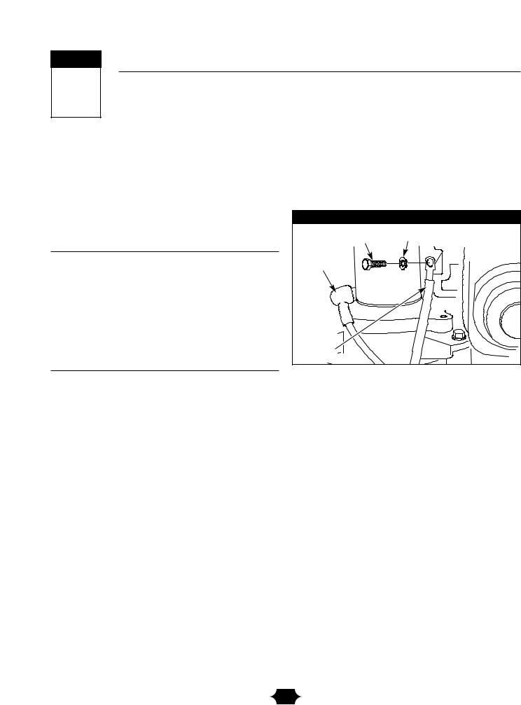
2.Attach negative battery cable with 5/16” x 3/4” screw and lock washer to the engine block, next to the starter (Figure 1).Tighten securely.
Figure 1 — Negative Battery Connection
Screw |
Washer |
Positive |
|
battery |
|
cable |
|
Negative |
|
battery |
|
cable |
|
6
Section 3: Assembly
Attach Handle
You will need two 1/2” or 13 mm wrenches to attach the handle.
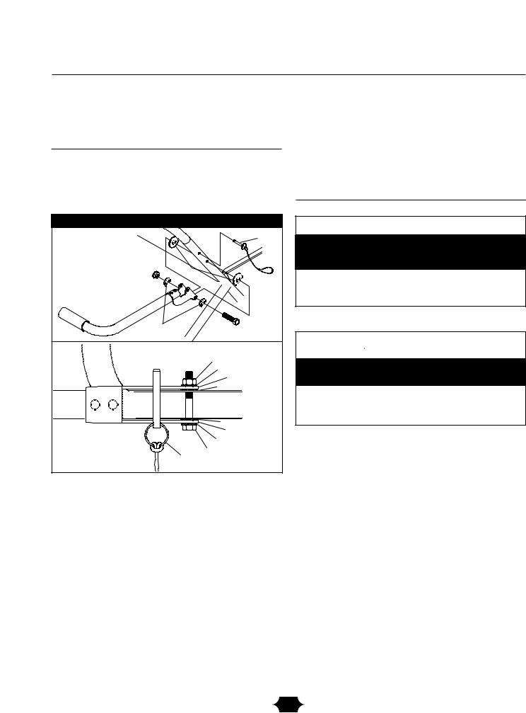
1.Attach handle to right side of generator frame (viewing unit from front), as shown in Figure 2, with a 60 mm capscrew, flat washers, nylon washers, and lock nut.
Figure 2 — Attach Handle
|
|
Handle Pin |
Lock Nut |
Nylon |
Washers |
|
||
|
|
|
Flat Washers |
Capscrew |
|
|
|
Nut |
|
|
Washer |
|
|
Handle Bracket |
|
|
Nylon Washer |
|
|
Nylon Washer |
|
|
Handle Bracket |
|
|
Washer |
|
|
60mm Capscrew |
|
Handle Pin |
|
NOTE: DO NOT overtighten. Handle must be able to move up and down freely.
2.Raise handle and insert handle pin to move generator.
BEFORE STARTING THE ENGINE
Add Engine Oil and Fuel
• Place generator on a level surface.
CAUTION
Any attempt to crank or start the engine before it has been properly filled with the recommended oil will result in equipment failure.
•Refer to engine manual for oil and fuel fill information.
•Damage to equipment resulting from failure to follow this instruction will void warranty.
•Refer to engine owner’s manual and follow oil and fuel recommendations and instructions.
 WARNING
Fill tank to approximately 2-1/4” below top of neck to allow for fuel expansion.
•Replace “1-1/2” with “2-1/4” fuel fill level given in engine manual.
•Failure to follow this instruction may cause fuel to overexpand and spill from tank.
NOTE: Check oil often during engine break–in. Refer to engine owner’s manual for recommendations.
NOTE: The generator assembly rotates on a prelubricated and sealed ball bearing that requires no additional lubrication for the life of the bearing.
7
Section Operation
4
USING THE GENERATOR
System Ground
The generator has a system ground that connects the generator frame components to the ground terminals on the AC output receptacles.The system ground is connected to the AC neutral wire (see “Equipment Description”, earlier in this manual).
Special Requirements
There may be Federal or State Occupational Safety and Health Administration (OSHA) regulations, local codes, or ordinances that apply to the intended use of the generator. Please consult a qualified electrician, electrical inspector, or the local agency having jurisdiction.
•In some areas, generators are required to be registered with local utility companies.
•If the generator is used at a construction site, there may be additional regulations which must be observed.
Connecting to a Building’s Electrical System
Connections for standby power to a building’s electrical system must be made by a qualified electrician.The connection must isolate the generator power from utility power, and must comply with all applicable laws and electrical codes.
 DANGER
Generator produces powerful voltage.
Failure to isolate generator from power utility can result in death or injury to electric utility workers due to backfeed of electrical energy.
•When using generator for backup power, notify utility company. Use approved transfer equipment to isolate generator from electric utility.
•Use a ground fault circuit interrupter (GFCI) in any damp or
highly conductive area, such as metal decking or steel work.
•DO NOT touch bare wires or receptacles.
•DO NOT use generator with electrical cords which are worn, frayed, bare or otherwise damaged.
•DO NOT operate generator in the rain.
•DO NOT handle generator or electrical cords while standing
in water, while barefoot, or while hands or feet are wet.
•DO NOT allow unqualified persons or children to operate or service generator.
OPERATING THE
GENERATOR
CAUTION
Exceeding generator’s wattage/amperage capacity can damage generator and/or electrical devices connected to it.
•See “Don’t Overload Generator” on page 13.
•Start generator and let engine stabilize before connecting electrical loads.
•Connect electrical loads in OFF position, then turn ON for operation.
•Turn electrical loads OFF and disconnect from generator before stopping generator.
IMPORTANT: Always unplug the battery float charger before starting the generator.
Starting the Engine
Disconnect all electrical loads from the generator. Follow start instruction steps in numerical order:
1.Make sure unit is on a level surface.
IMPORTANT: Failure to start and operate unit on a level surface will cause the unit not to start or shut down during operation.
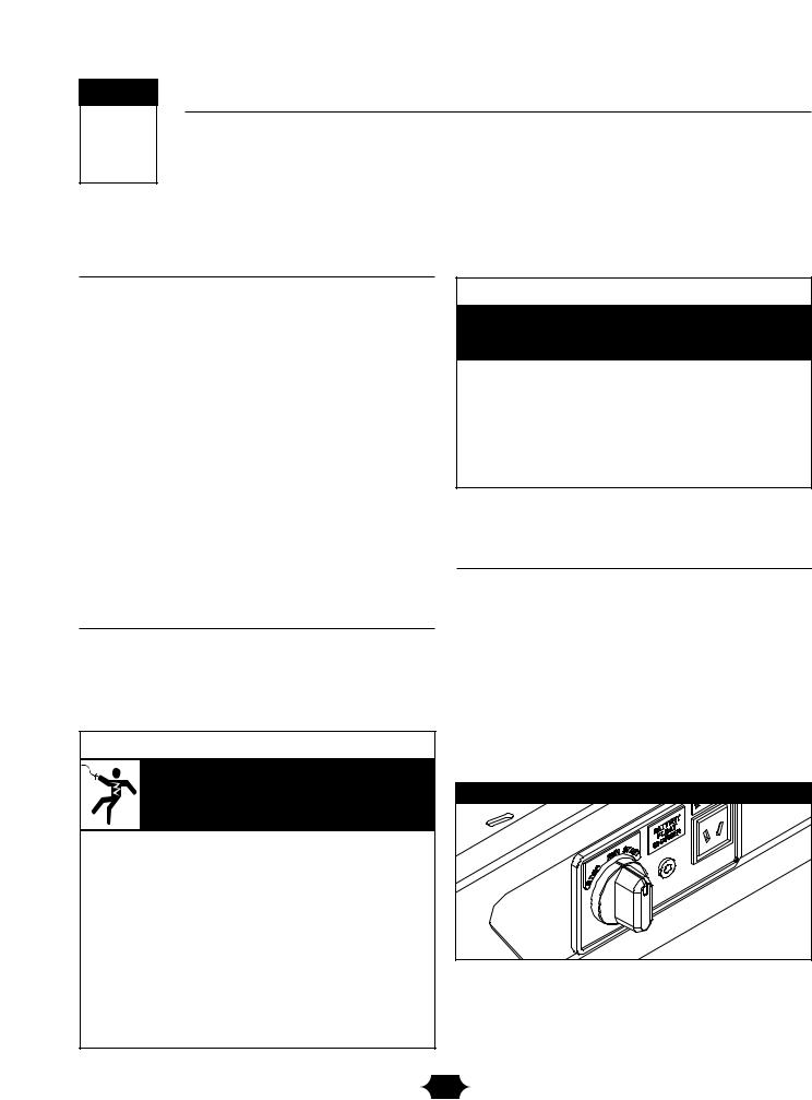
2.Follow start instructions given in engine owner’s manual and turn start switch on generator to “Start” position (Figure 3).To prolong life of starter components, DO NOT hold starter switch in “Start” position for more than 15 seconds, and pause for 1 minute.
Figure 3 — Starter Switch
NOTE: If engine starts but fails to run, or if unit shuts down during operation, make sure unit is on a level surface and check for proper oil level in crankcase.This unit may be equipped with a low oil protection device. See engine manual.
8
Section 4: Operation
Jump Start Procedure
If the generator’s starting battery fails, use the following instructions to jump start your generator.You can jump start the generator using any 12 Volt automotive or utility style storage battery.
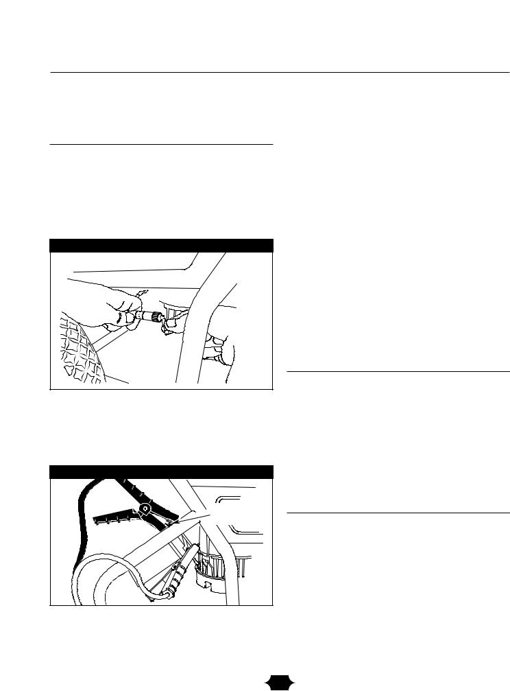
1.Unscrew the fuse holder and remove the generator’s 10 Amp in-line fuse (Figure 4).Verify the fuse is good or replace with a known good fuse. Reinstall fuse in the fuse holder.
Figure 4 — In-Line Fuse
2.Slide the red rubber boot off the generator’s battery terminal and push it onto the red wire, thus uncovering the POSITIVE battery terminal.
3.Using standard automotive jumper cables, connect the RED jumper cable clamp to the generator’s POSITIVE battery terminal (Figure 5).
Figure 5 — Jumper Cable Connections
Grounding |
Fastener |
4.Connect the other RED jumper cable clamp to the starting battery’s POSITIVE battery terminal.
5.Connect the BLACK jumper cable clamp to the starting battery’s NEGATIVE battery terminal.
6.Connect the other BLACK jumper cable clamp to the GROUNDING FASTENER on the generator, as shown in Figure 5.
7.Start the generator as described in “Starting the Engine” and remove jumper cables in reverse order of connections.
8.Slide the red rubber boot back onto the generator’s POSITIVE battery terminal.
If you have any questions, please call the Generator Helpline at 1-888-611-6708, M-F 8-5 CT.
IMPORTANT: When jump starting, always wear proper eye protection and never lean over battery. Inspect both batteries before connecting booster cables. DO NOT jump start a damaged battery. Be sure vent caps are tight and level.
Connecting Electrical Loads
•Let engine stabilize and warm up for a few minutes after starting.
•Plug in and turn on the desired 120 and/or 240 Volt AC, single phase, 60 Hz electrical loads.
•DO NOT connect 240 Volt loads to the 120 Volt duplex receptacles.
•DO NOT connect 3–phase loads to the generator.
•DO NOT connect 50 Hz loads to the generator.
•DO NOT OVERLOAD GENERATOR. See “Don’t Overload Generator” on page 13.
Stopping the Engine
1.Unplug all electrical loads from generator panel receptacles. NEVER start or stop engine with electrical devices plugged in and turned ON.
2.Let engine run at no-load for several minutes to stabilize internal temperatures of engine and generator.
3.Turn start switch to “Stop” position.
9
Section 4: Operation
Charging a Battery
Your generator has the capability of recharging a discharged 12 Volt automotive or utility style storage battery. DO NOT use the unit to charge any 6 Volt batteries. DO NOT use the unit to crank an engine having a discharged battery.
 DANGER
Storage batteries give off explosive hydrogen gas during recharging.
Hydrogen gas stays near battery for a long time after battery has been charged.
Slightest spark will ignite hydrogen and cause explosion.
You can be blinded or severely injured.
Battery electrolyte fluid contains acid and is extremely caustic.
Contact with battery fluid will cause severe chemical burns.
•DO NOT allow any open flame, spark, heat, or lit cigarette during and for several minutes after charging a battery.
•Wear protective goggles, rubber apron, and rubber gloves.
To recharge 12 Volt batteries, proceed as follows:
1.Check fluid level in all battery cells. If necessary, add ONLY distilled water to cover separators in battery cells. DO NOT use tap water.
2.If battery is equipped with vent caps, make sure they are installed and are tight.
3.If necessary, clean battery terminals.
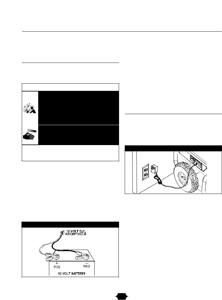
4.Connect battery charge cable connector plug to panel receptacle identified by the words “12-VOLTS D.C.”.
5.Connect battery charge cable clamp with red handle to the positive (+) battery terminal (Figure 6).
Figure 6 — Battery Connections
6.Connect battery charge cable clamp with black handle to the negative (–) battery terminal (Figure 6).
7.Start engine. Let engine run while battery recharges.
8.When battery has charged, shut down engine
NOTE: Use an automotive hydrometer to test battery state of charge and condition. Follow the hydrometer manufacturer’s instructions carefully. Generally, a battery is considered to be at 100% state of charge when specific gravity of its fluid (as measured by hydrometer) is 1.260 or higher.
How to Use the Battery Charger
Use battery float charger jack to keep the starting battery charged and ready for use. Battery charging should be done in a dry location, such as inside a garage.
1.Plug charger into unit’s “Battery Float Charger” jack, which is located next to starter switch (Figure 7). Plug
battery charger into a 120 |
. |
Figure 7 — Battery Charger Jack
2.Unplug charger from unit and wall outlet when generator is being started and while in operation.
3.Keep this charger plugged in when generator is not in use to prolong battery life.The charger has a built in float equalizer and will not overcharge the battery, even when plugged in for an extended period of time.
IMPORTANT: See “Battery Maintenance” on page 15 for additional information.
10
Section 4: Operation
COLD WEATHER |
GENERATOR ADAPTER |
OPERATION |
CORD SET |
Under certain weather conditions (temperatures below 40°F [4°C] and a high dew point), your generator may experience icing of the carburetor and/or the crankcase breather system.
Build a structure that will enclose three sides and top of generator:
1.Make sure entire muffler-side of generator is exposed. Note that your generator may appear different from that shown in Figure 8.
Figure 8 — Permanent Cold Weather Shelter
Wind
2.Ensure a minimum of two feet clearance between open side of box and nearest object.
3.Face exposed end away from wind and elements.
4.Enclosure should hold enough heat created by generator to prevent problems.
 DANGER
Running generator gives off carbon monoxide, an odorless, colorless, poison gas.
Breathing carbon monoxide will cause nausea, fainting or death.
•Operate generator ONLY outdoors.
•Keep at least 2 feet of clearance on all sides of generator for adequate ventilation.
•DO NOT operate generator inside any building or enclosure, including the generator compartment of a recreational vehicle (RV).
•Remove generator from shelter when temperature is above 40°F [4°C].
The generator is equipped with a 25’ generator adapter cord set designed for a 240 Volt, 30 Amp grounded neutral circuit (Figure 9).The generator adapter cord set provides a convenient supply of emergency power into your dwelling so that your generator can be operated safely outside.
Figure 9 — Generator Adapter Cord Set
The maximum load on each outlet is 20 Amps.The maximum total load on both yellow wire outlets or both black wire outlets is 30 Amps.
NOTE: Follow all safety precautions when connecting any extension cord or device to the generator.
11
Section 4: Operation
RECEPTACLES
 CAUTION
Receptacles may be marked with rating value greater than generator output capacity.
•NEVER attempt to power a device requiring more amperage than generator or receptacle can supply.
•DO NOT overload the generator. See “Don’t Overload Generator”.
12 Volt DC, 10 Amp Receptacle
This receptacle allows you to recharge a 12 Volt automotive or utility style storage battery with the battery charge cables provided (Figure 10).
Figure 10 — 12 Volt DC, 10 Amp Receptacle
This receptacle can not recharge 6 Volt batteries and can not be used to crank an engine having a discharged battery. See the section “Charging a Battery” (page 10) before attempting to recharge a battery.
120 Volt AC, 20 Amp, Duplex
Receptacles
Each duplex receptacle (Figure 11) is protected against overload by a push–to–reset circuit breaker.
Figure 11 — 120 Volt, 20 Amp Duplex Receptacle
Use each receptacle to operate 120 Volt AC, single–phase, 60 Hz electrical loads requiring up to 2,400 watts (2.4 kW) at 20 Amps of current. Use cord sets that are rated for 125 Volt AC loads at 20 Amps (or greater).
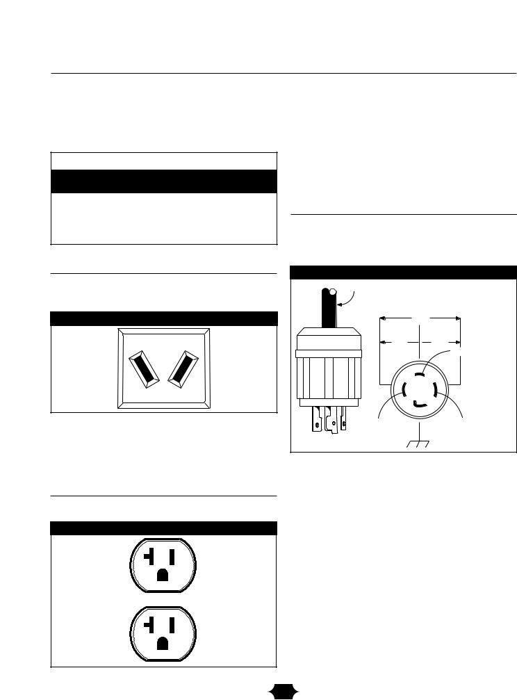
120/240 Volt AC, 30 Amp, Locking
Receptacle
Use a NEMA L14–30 plug with this receptacle. Connect a 4–wire cord set rated for 250 Volt AC loads at 30 Amps (or greater) (Figure 12).You can use the same 4–wire cord if you plan to run a 120 Volt load.
Figure 12 — 120/240 Volt AC, 30 Amp Receptacle
4-Wire Cord Set
240V
120V  120V
120V
W (Neutral)
Y (Hot) |
X (Hot) |
NEMA L14-30 |
Ground (Green) |
This receptacle powers 120/240 Volt AC, 60 Hz, single phase loads requiring up to 7,200 watts of power (7.2 kW) at 30 Amps for 120 Volts or 240 Volts.The outlet is protected by a rocker switch circuit breaker.
12

Section 4: Operation
DON'T OVERLOAD
GENERATOR
Capacity
You must make sure your generator can supply enough rated (running) and surge (starting) watts for the items you will power at the same time. Follow these simple steps:
1.Select the items you will power at the same time.
2.Total the rated (running) watts of these items.This is the amount of power your generator must produce to keep your items running. See Figure 13.
3.Estimate how many surge (starting) watts you will need. Surge wattage is the short burst of power needed to start electric motor-driven tools or appliances such as a circular saw or refrigerator. Because not all motors start at the same time, total surge watts can be estimated by adding only the item(s) with the highest additional surge watts to the total rated watts from step 2.
Example:
Tool or Appliance |
Rated (Running) |
|
Additional Surge |
|||
Watts |
|
|
(Starting) Watts |
|||
|
|
|
||||
Window Air |
|
1200 |
|
|
1800 |
|
Conditioner |
|
|
|
|
|
|
Refrigerator |
|
800 |
|
|
1600 |
|
Deep Freezer |
|
500 |
|
|
500 |
|
Television |
|
500 |
|
|
- |
|
Light (75 Watts) |
|
75 |
|
|
- |
|
|
3075 Total |
|
1800 Highest |
|||
|
Running Watts |
|
Surge Watts |
|||
Total Rated (Running) Watts |
|
= 3075 |
|
|
||
Highest Additional Surge Watts |
= 1800 |
|
|
|||
Total Generator Output Required |
= 4875 |
|
|
|||
Power Management
To prolong the life of your generator and attached devices, it is important to take care when adding electrical loads to your generator.There should be nothing connected to the generator outlets before starting it's engine.The correct and safe way to manage generator power is to sequentially add loads as follows:
1.With nothing connected to the generator, start the engine as described in this manual.
2.Plug in and turn on the first load, preferably the largest load you have.
3.Permit the generator output to stabilize (engine runs smoothly and attached device operates properly.
4.Plug in and turn on the next load.
5.Again, permit the generator to stabilize.
6.Repeat steps 4 and 5 for each additional load.
NEVER add more loads than the generator capacity.Take special care to consider surge loads in generator capacity, as described above.
Figure 13 - Wattage Reference Chart
|
Rated* |
Additional |
|
|
Surge |
||
Tool or Appliance |
(Running) |
||
(Starting) |
|||
|
Watts |
||
|
Watts |
||
|
|
||
Essentials |
|
|
|
Light Bulb - 75 watt |
75 |
- |
|
Deep Freezer |
500 |
500 |
|
Sump Pump |
800 |
1200 |
|
Refrigerator/Freezer - 18 Cu. Ft. |
800 |
1600 |
|
Water Well Pump - 1/3 HP |
1000 |
2000 |
|
Heating/Cooling |
|
|
|
Window AC - 10,000 BTU |
1200 |
1800 |
|
Window Fan |
300 |
600 |
|
Furnace Fan Blower - 1/2 HP |
800 |
1300 |
|
Kitchen |
|
|
|
Microwave Oven - 1000 Watt |
1000 |
- |
|
Coffee Maker |
1500 |
- |
|
Electric Stove - Single Element |
1500 |
- |
|
Hot Plate |
2500 |
- |
|
Family Room |
|
|
|
DVD/CD Player |
100 |
- |
|
VCR |
100 |
- |
|
Stereo Receiver |
450 |
- |
|
Color Television - 27” |
500 |
- |
|
Personal Computer w/17” monitor |
800 |
- |
|
Other |
|
|
|
Security System |
180 |
- |
|
AM/FM Clock Radio |
300 |
- |
|
Garage Door Opener - 1/2 HP |
480 |
520 |
|
Electric Water Heater - 40 Gallon |
4000 |
- |
|
DIY/Job Site |
|
|
|
Quartz Halogen Work Light |
1000 |
- |
|
Airless Sprayer - 1/3 HP |
600 |
1200 |
|
Reciprocating Saw |
960 |
960 |
|
Electric Drill - 1/2 HP |
1000 |
1000 |
|
Circular Saw - 7 1/4” |
1500 |
1500 |
|
Miter Saw - 10” |
1800 |
1800 |
|
Table Planer - 6” |
1800 |
1800 |
|
Table Saw/Radial Arm Saw - 10” |
2000 |
2000 |
|
Air Compressor - 1-1/2 HP |
2500 |
2500 |
*Wattages listed are approximate only. Check tool or appliance for actual wattage.
13
Section Maintenance
5
GENERAL MAINTENANCE RECOMMENDATIONS
The Owner/Operator is responsible for making sure that all periodic maintenance tasks are completed on a timely basis; that all discrepancies are corrected; and that the unit is kept clean and properly stored. NEVER operate a damaged or defective generator.
NOTE: If equipped with inflatable tires, keep the air pressure at the value marked on the tire or within 15 and 40 psi.
Engine Maintenance
See engine owner’s manual for instructions.
An oil drain tray is provided for your convenience to change the oil and oil filter. Store tray in a convenient location for periodic maintenance.
Changing Oil
1.Place the half moon notch in the oil drain tray under the oil drain plug (Figure 14).
Figure 14 — Changing Oil With Oil Drain Tray
drain tray notch |
drain tray foot |
2.Place the oil drain tray foot tab in the slot on the base of the generator, as shown.
3.Follow the instructions given in the engine owner’s manual for draining oil.
4.After oil has drained, reinstall the oil drain plug.
5.Remove the oil drain tray from under the oil drain plug and clean up any spilled oil.
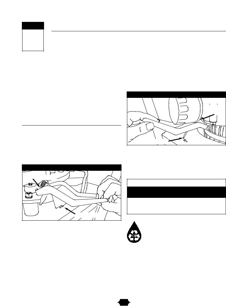
Changing Oil Filter
1.Place the half moon notch in the oil drain tray under the oil filter (Figure 15).
Figure 15 — Changing Oil Filter With Oil Drain Tray
drain tray |
notch |
drain tray foot |
2.Place the oil drain tray foot tab in the slot on the base of the generator, as shown.
3.Follow the instructions given in the engine owner’s manual for changing oil filter and adding oil.
4.Remove the oil drain tray from under the oil filter and clean up any spilled oil.
 CAUTION
Avoid prolonged or repeated skin contact with used motor oil.
•Used motor oil has been shown to cause skin cancer in certain laboratory animals.
•Thoroughly wash exposed areas with soap and water.
KEEP OUT OF REACH OF CHILDREN. DON'T POLLUTE. CONSERVE RESOURCES. RETURN USED OIL TO COLLECTION CENTERS.
14
 Loading...