


34061
OWNER’S MANUAL
Sickle Bar Mowers
• Safety
• Assembly
• Controls and Features
• Operation
• Maintenance
• Parts List
GARDEN WAY INCORPORATED
Models
34061 – 34", 3-1/2 HP Recoil Start
34062 – 38", 4HP Recoil Start
34337 – 34", 4HP Recoil Start
34063 – 42", 5HP Recoil Start
34064 – 42", 5HP Electric Start
SAFETY FIRST!
Before operating this equipment, read this
Owner's Manual and the separate manual
supplied by the engine manufacturer.

2
Dear Owner:
Thank you for purchasing our product. We feel you now own
one of the finest pieces of outdoor power equipment available.
Our equipment is carefully designed, engineered and manufactured for excellent performance if properly operated and maintained.
Read this manual carefully to familiarize yourself with the unit,
its features, and its safe operation. Be sure that you and any
other operators carefully follow the recommended safety practices at all times. Failure to do so could result in personal injury
or property damage.
This is a safety, operation and general maintenance manual
which does not attempt to cover major repairs. All information
in this manual is based on the latest product information available at the time of printing. This manual is considered a permanent part of the unit and it must stay with the unit if resold. A
replacement manual can be obtained from the factory or an
authorized dealer.
Please fill out and return the postpaid owner registration card
included with this manual. The purpose of the card is to register
each unit and owner at the factory to provide product updates
and warranty service.
If you have any problems or questions concerning the unit,
please contact your local authorized dealer or the factory (see
back cover of this manual). We want to be sure that you are
completely satisfied at all times.
INTRODUCTION ................................................. 2
Service Information ...................................................... 3
Identification Numbers ................................................. 3
California Operators Warning ....................................... 3
SAFETY .......................................................... 3
Safety Decals ................................................................ 5
ASSEMBLY ...................................................... 6
FEATURES AND CONTROLS ................................... 14
Throttle/Choke Control Lever ........................................ 14
Operator Presence Controls (OPC) ............................... 14
Wheel Drive Levers ....................................................... 14
Engine Oil Dipstick/Fill Hole .......................................... 14
Shoes ........................................................................... 14
Cutter Bar (with guard) ................................................. 15
Fuel Tank Cap ............................................................... 15
Starter Rope Handle ..................................................... 15
Engine Keyswitch (electric-start units).......................... 15
Cutter Bar Lever ........................................................... 15
Weed Diverter ............................................................... 15
Engine Primer Bulb ....................................................... 15
OPERATION ..................................................... 16
Pre-start Checklist ........................................................ 16
Starting the Engine ....................................................... 16
Stopping the Engine...................................................... 17
Operator Presence Controls (OPC) System Test .......... 17
Operation....................................................................... 18
Operating on Slopes...................................................... 19
Stopping ....................................................................... 19
MAINTENANCE ................................................. 20
Maintenance Schedule................................................... 20
Tire Pressure................................................................. 20
Clearing Wheel Wrap .................................................... 20
Wheel Drive Control Rod Adjustment ........................... 20
Cutter Bar Drive Belt Removal/Replacement ................ 21
Cutter Bar Belt Guide Adjustment ................................ 21
Wheel Drive Belt Adjustment ........................................ 21
Wheel Drive Belt Removal/Replacement ....................... 21
Wheel Drive Belt Guide Adjustment .............................. 21
Drive Chain Adjustment and Lubrication ...................... 22
Cutter Bar Maintenance ............................................ 22-24
High-Wear Parts ........................................................... 24
Housing Assembly Tightening Sequence....................... 26
Front Housing Removal................................................. 26
Eccentric Shaft Removal/Replacement.......................... 26
Engine Maintenance.................................................. 26-27
Battery Maintenance...................................................... 27
Check and Tighten Hardware......................................... 27
Lubrication.................................................................... 27
Storage ......................................................................... 28
Troubleshooting ....................................................... 28-29
PARTS LIST...................................................... 30
CUSTOMER SERVICE INFORMATION ............. BACK COVER
T able of Contents
The engine exhaust from this product contains
chemicals known to the State of California to cause
cancer, birth defects or other reproductive harm.
WARNING
Safety Alert Symbol
This is a safety alert symbol. It is used in this
manual and on the unit to alert you to potential hazards. When you see this symbol, read and obey the
message that follows it. Failure to obey safety messages could result in personal injury or property
damage.
See Back Cover for
Customer Service Information
Left and Right Sides
Left and right sides of the unit are determined by standing in
the operator position and facing the direction of forward
travel.

PREPARATION
1. Unit is capable of amputating hands
and feet and
throwing
objects.
Failure to
observe the
following safety instructions could result
in serious injury or property damage.
2. Serious accidents which may cause
injury or property damage can occur if the
following safety guidelines are not followed. The operator is solely responsible
for accidents or hazards that occur when
using the unit. Preventing accidents is the
responsibility of every equipment operator. Accidents can be prevented. Be
careful before, during and immediately
after use of any powered equipment. The
following general safety precautions must
be fully understood and followed during
operation. Review these instructions frequently and never take chances. If you do
not understand any part of this manual or
need assistance, contact your dealer or
our service department.
TRAINING
1. Read, understand, and follow this
Owner’s Manual, the separate engine
owner’s manual, and all other literature
received before you use the unit.
Be thoroughly familiar with the controls
and proper use of the unit. Know how to
stop the unit and disengage controls
quickly in case of emergency.
Read and follow all safety information in
this manual. Failure to comply could result
in serious personal injury or property
damage.
Make sure all operators of the equipment
read, understand, and follow these safety
instructions.
2. Never allow children to operate the unit.
Do not allow adults to operate the unit
without proper instruction. Do not allow
irresponsible adults to operate the unit.
3. Keep the operating area (within 25 feet
of unit) clear of all people (especially children) and pets.
PREPARATION
1. Wear proper clothing when operating
unit. Always wear sturdy footwear (preferably steel-toed shoes) and hearing protection during operation.
a. Wear heavy leather gloves whenever
working near or servicing any cutting
edges on the unit.
b. Do not wear loose-fitting clothing,
jewelry, scarves, ties, etc., which may
get caught in moving parts. Tie up or
restrain hair.
c. Do not operate the unit while bare-
foot. Do not wear sandals.
d. Wear long trousers.
e. Wear hearing protection.
2. Do not operate the unit when tired, ill
or under the influence of alcohol and/or
other drugs.
3. Be prepared for an emergency. Keep a
first aid kit and fire extinguisher handy.
Keep emergency telephone numbers for
ambulance, fire, hospital, doctor and
rescue near your telephone.
4. When charging the battery on electricstart units, use only the battery charger
provided with the unit.
5. Do not operate the unit if the cutter bar
assembly is not securely installed and
operating properly.
6. Mow only during daylight or in good
artificial light.
7. Never operate the unit in wet grass.
Always be sure of your footing. Always hold
handlebar grips firmly, and walk––never
run.
25 Ft.
25 Ft.
25 Ft.
25 Ft.
Safety
1
Section
3
SPARK ARRESTER WARNING TO RESIDENTS
OF CALIFORNIA AND SEVERAL OTHER STATES
Under California law, and under the laws of several
other states, you are not permitted to operate an
internal combustion engine using hydrocarbon fuels on
any forest, brush, hay, grain, or grass covered land; or
land covered by any flammable agricultural crop
without an engine spark arrester in continuous effective
working order.
The engine on the unit is an internal combustion engine
which burns gasoline, a hydrocarbon fuel, and must be
equipped with a spark arrester muffler in continuous
effective working order. The spark arrester must be
attached to the engine exhaust system in such a
manner that flames or heat from the system will not
ignite flammable material. Failure of the owner/operator of the unit to comply with this regulation is a misdemeanor under California law (and other states) and
may also be a violation of other state and/or federal
regulations, laws, ordinances or codes. Contact your
local fire marshal or forest service for specific information about which regulations apply in your area.
Throttle/Choke Control Lever
Wheel Drive
Levers
Cutter Bar and Guard
Cutter Bar Lever
(on rear of unit)
Operator Presence Controls
Figure 1-1

4 Section 1: Safety
BEFORE OPERATION
1. Before each use, thoroughly inspect the
mowing area. Remove all
metal, debris, and other
hazards. Inspect for holes,
ruts or bumps. Uneven terrain could overturn the unit.
Tall vegetation can hide
hazards.
2. Never operate the unit without all
guards in place and working properly
(except for the plastic blade protector,
which should be removed before starting
the engine).
3. Before removing or installing the
plastic blade protector, shut the engine
off, disconnect the spark plug wire, and
prevent it from touching the spark plug.
On electric start models, also remove the
ignition key from the keyswitch.
4. Check the operation of the control
levers under each handlebar grip. See the
"Operation" Section in this manual for specific instructions. Do not use the unit if
control levers are not functioning properly.
CORRECT ANY MALFUNCTION BEFORE
USING THE UNIT!
HANDLING GASOLINE
1. Use extreme care in handling gasoline and other fuels.
Gasoline is highly
flammable and its vapors
are volatile, explosive,
and dangerous. Keep gasoline and gasoline containers away from hot engine
exhaust. Never allow flame, sparks,
smoking materials or other hot objects
near gasoline, gasoline fumes, the fuel
container or fuel tank.
2. Use an approved fuel container only.
Wipe up any spilled gasoline immediately.
3. Leave one inch of air space at top of
fuel tank to allow room for expansion.
4. Store gasoline in a cool, well-ventilated
area. Never store unit or fuel container
inside where there is an open flame or
spark, such as a hot water heater, furnace,
etc.
5. Never remove fuel fill cap, or add fuel
to fuel tank, if engine is running or hot.
Allow the engine to cool for several minutes before filling the fuel tank. Always
replace fuel fill cap before starting engine.
6. Never refuel unit indoors. Refuel outdoors in a well-ventilated area only.
7. Check the gasoline level in the fuel tank
outdoors, before starting the engine.
Reinstall the fuel tank cap securely and
clean up any spilled gasoline before
starting the engine.
8. Do not smoke while mowing.
9. Move the unit away from gasoline
fumes before starting the engine.
OPERATION
1. Keep the plastic blade protector on the
cutter bar blade until you are ready to start
the engine.
2. Do not put hands or feet near or under
any moving parts. Keep clear of the cutter
bar at all times while the engine is
running.
3. Never leave the operator position while
the engine is running. Stop
the engine, disconnect the
spark plug wire and move it
away from the spark plug to
help prevent accidental
starting whenever leaving the unit unattended. On electric start models, remove
the ignition key to help prevent accidental
starting or unauthorized use.
4. Before removing or installing the
plastic blade protector, shut the engine
off, disconnect the spark plug wire, and
prevent it from touching the spark plug.
On electric start models, also remove the
ignition key from the keyswitch.
5. Do not change the engine governor setting. Over-speeding may damage the
engine and unit and will void the warranty.
See an authorized engine service dealer if
an engine problem exists.
6. Disengage the cutter bar when
crossing gravel drives, walkways or roads.
7. Watch for, and avoid, traffic when
operating near roadways.
8. Disengage the cutter bar
drive and the wheel drive if
you are approached by a child,
inattentive person or a pet.
9. Before inspecting, adjusting or
repairing the unit or cutter
bar, stop the engine, let all
moving parts come to a
complete stop, disconnect
the spark plug wire, and
install the plastic blade guard. On electric
start models, remove the ignition key from
the keyswitch.
10. If the unit should start to vibrate
abnormally, stop the engine, wait for all
moving parts to stop completely, disconnect the spark plug wire and prevent it
from touching the spark plug. Remove the
engine ignition key on electric start
models. Inspect the unit for damage.
Repair any damage before continuing.
11. If the unit should strike a foreign
object, stop the engine, wait for all moving
parts to stop completely, disconnect the
spark plug wire and prevent it from
touching the spark plug. Remove the
engine ignition key on electric start
models. Inspect the unit for damage.
Repair any damage before continuing.
12. Do not run the engine in an enclosed
area. Engine exhaust contains carbon
monoxide, a deadly, poisonous gas that is
odorless, colorless and tasteless. Always
run the engine outdoors with adequate
ventilation.
13. Always mow across the face of slopes.
Do not operate unit on slopes steeper than
15°.
14. Keep all movements on a slope slow
and gradual. Do not make sudden changes
in speed or direction.
15. Do not touch engine parts which may
be hot from operation. Let parts cool for
several minutes before going near them.
16. Keep children out of the mowing area
and under the supervision of a responsible
adult other than the unit operator.
17. Before and when backing, check for
and avoid obstacles and hazards.
18. Disengage the cutter bar drive when
not mowing.
19. Do not mow near drop-offs, ditches or
embankments. If a wheel drops off an
edge, the unit could suddenly overturn.
20. To help reduce fire hazard, keep the
engine free of grass, leaves, grease and
other debris.
CHILDREN
1. Tragic accidents can occur if the operator is not alert to the presence of children. Children are often attracted to the
unit and the mowing activity. Never
assume that children will remain where
you last saw them.
2. Never allow children to operate the
unit, even under adult supervision. Local
regulations may restrict operator age. Only
allow responsible adults, who are familiar
with these instructions, to operate the
unit.

Section 1: Safety 5
3. Never carry children as passengers.
Do not carry ANY passengers. They may
fall off, become seriously injured, or interfere with safe unit operation.
4. Keep children out of the work area and
under the watchful care of a responsible
adult other than the unit operator.
5. Be alert and turn unit off if children
enter the area.
6. Before and when backing, look behind
and down for children.
7. Use extra care when approaching blind
corners, shrubs, trees, or other objects
that may obscure vision.
8. Keep children away while performing
maintenance or adjustments.
MAINTENANCE AND STORAGE
1. Before inspecting, cleaning, adjusting
or repairing the unit, stop the engine, let
all moving parts come to a
complete stop, disconnect
the spark plug wire, and
install the plastic blade
guard on the cutter bar. On
electric start models, remove the ignition
key from the keyswitch.
2. Always wear sturdy footwear (preferably steel-toed shoes), long trousers,
hearing and eye protection while doing
any maintenance on the unit. Do not wear
loose-fitting clothing, jewelry, scarves,
ties, etc., which could get caught in
moving parts. Tie up or restrain hair.
3. Install the plastic blade guard before
removing the cutter bar assembly and
wear sturdy leather gloves to help protect
your fingers and hands.
4. Keep children away while performing
maintenance or adjustments.
5. Remove any metal jewelry when
working on or near electrical system components.
6. Use only original equipment replacement parts. Parts manufactured by others
could create a hazard even though they
may fit on the unit.
7. Keep the equipment in safe working
condition. Keep all nuts, bolts and screws
tight. Frequently check the engine
mounting bolts and cutter bar mounting
bolts for tightness.
8. Provide safe, adequate light in your
work area. NEVER USE AN OPEN FLAME
FOR ILLUMINATION! Use only a portable
safety light enclosed in a wire cage for
working on unit. NOTE:
Hot filaments from a
broken light bulb can
ignite spilled fuel or oil.
9. If the unit has gasoline in its fuel tank,
do not store it inside a building where
fumes from the gasoline could reach an
open flame or spark. Let the engine cool
before storing the unit.
10. Store gasoline in a cool, well-ventilated area, away from spark- or flame-producing equipment. Store gasoline in an
approved container, away from children.
11. Keep unit free of grass, leaves or
build-up of other debris. Clean up oil or
fuel spillage. Allow unit to cool before
storing.
12. Replace muffler if worn or defective.
13. Use extra care when loading or
unloading unit into a trailer or truck.
14. Do not use food or beverage containers to store waste materials. Using
such containers could result in accidental
poisoning.
ENGINE
1. Before starting the engine or operating
the unit, read the separate engine manual
completely. Read and follow all safety
instructions provided in that manual.
2. BEFORE SERVICING THE ENGINE:
Disconnect the spark plug wire and keep it
from touching the spark plug.
3. Keep the engine free of grass, leaves,
oil, and grease.
4. Engine exhaust is extremely hot. Keep
grass, oil, fuel, and other combustible
materials far away from engine exhaust.
5. Do not change the engine governor setting. Over-speeding may damage the
engine and unit and will void the warranty.
See an authorized engine service dealer if
a problem exists.
6. Never run an internal combustion
engine inside a closed area. Engine
exhaust contains carbon monoxide gas, a
deadly poison. Carbon monoxide is odorless, colorless and tasteless. Do not
operate the unit near buildings, windows,
or air conditioners. If the engine is run in a
garage, open all doors and allow for adequate ventilation.
Place Hand Here When
Pulling Starter Rope
Hot Surfaces
Warning
Sharp Cutter Bar
Blades Danger
Danger - Keep Hands
and Feet Away
On Rear Panel
Warning - Operating
Engine - Electric
Start Only
Cover “Top” Decal
Engine Throttle Settings
SAFETY DECAL LOCATION
Operator Presence
Controls
SAFETY DECALS
Keep all safety decals clean and in
good condition. The location of each
decal is shown in Figure 1-2.
Refer to the Parts List for ordering
replacement decals.
Figure 1-2
Assembly
2
Section
6
BEFORE ASSEMBLY
Carefully follow all steps in this section to
assemble the unit.
CARTON INSPECTION
Inspect the unit immediately after delivery.
Check the carton and contents for any
damage.
Contact the carrier (trucking company)
immediately if the unit is damaged. Inform
the carrier that you wish to file a claim.
The carrier will let you know how to proceed with the claim. To protect your
rights, file a written claim with the carrier
within 15 days of receiving the unit. Contact our service department if you need
assistance.
Do not start the engine until oil is added!
The engine is shipped without oil.
Engine damage will occur if engine is
started before oil is added.
IMPORTANT: Oil must be added before
starting the engine. Starting or operating
the engine without oil will damage the
engine and void the warranty. See the
engine manual.
Do not overfill engine with oil. Engine
damage will occur.
Cutter bar blades are extremely sharp.
To help avoid serious injury:
• Keep the plastic guard on the CUTTER
BAR ASSEMBLY when the unit is not
running.
• Wear heavy leather gloves when han-
dling the cutter bar.
• Do not place fingers between blades.
Amputation could result.
UNPACKING THE UNIT
The cutter bar blade and attached plastic
blade guard are packaged separately
within the main shipping crate. Leave the
cutter bar blade attached to the shipping
pallet until instructed to remove it.
The handlebars are packed on each side of
the unit, connected with wiring to the
underside of the unit. IMPORTANT: Do
not damage the wiring when removing the
handlebars from the carton.
The included parts and hardware required
for assembly are listed on the following
pages.
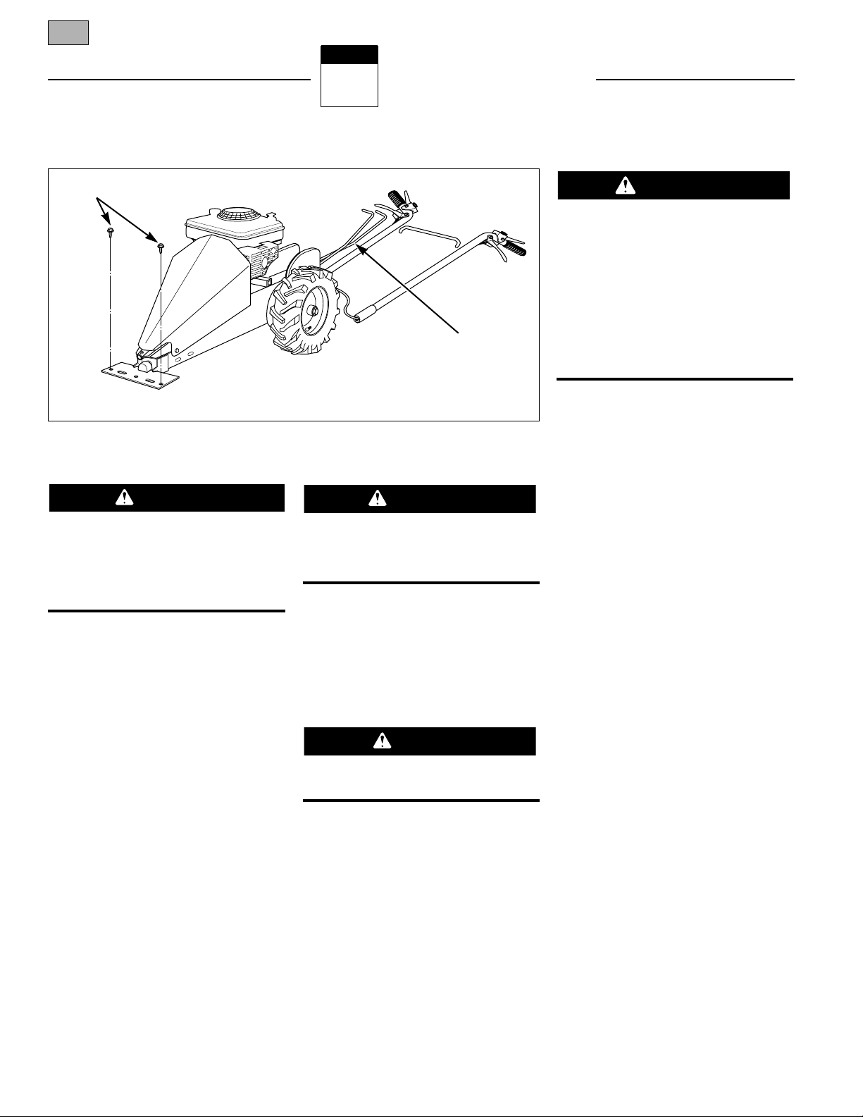
Remove and discard the two screws that
secure the front of the unit to the wooden
pallet (see Fig. 2-1). However, leave the
unit on the pallet until instructed to
remove it. Fig. 2-1 shows the position of
the unit for assembly.
TOOLS/MATERIALS NEEDED
(2 ea.) Wrenches: 7/16", 1/2", 9/16" (or
adjustable wrenches)
(1) Adjustable Wrench
(1) 13mm Socket
(1) Phillips (or thin straight blade)
Screwdriver
(1) All-purpose Oil
(1) Tire Pressure Gauge
(1) Measuring Tape or Ruler
DANGER
CAUTION
WARNING
Fig. 2-1
Remove shipping
screws
Remove control rods
from handlebar
To prevent personal injury or property
damage, do not start the engine until all
assembly steps are complete and you
have read and understand the safety and
operating instructions in this Manual
and the engine manual.
WARNING
Section 2: Assembly 7
2
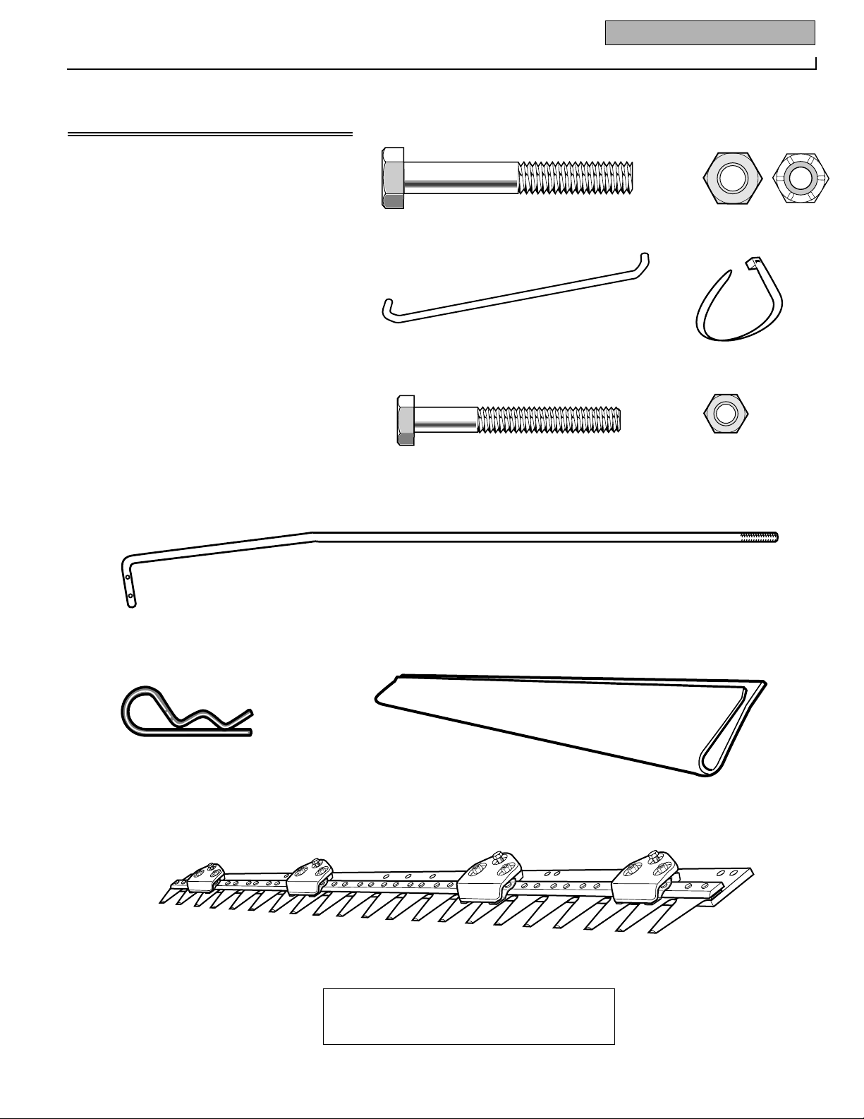
Ref. Description Qty.
Right Handlebar (shipped connected to
unit by wiring)...............................................1
Left Handlebar (shipped connected to
unit by wiring)...............................................1
1 Hex Head Capscrew, 5/16"–18 x 2-1/4" ........2
2 Locknut, 5/16"–18.......................................10
3 Handlebar Bridge..........................................1
4 Cable Ties (total of six - two already
installed on unit)...........................................4
5 Hex Head Capscrew, 1/4"–20 x 2".................1
6 Locknut, 1/4".................................................1
7 Control Rod..................................................2
8 Hair Pin ..................................................2
9 Plastic Blade Guard (on blade)......................1
10 Cutter Bar......................................................1
HARDWARE IS APPROXIMATE SIZE SHOWN
Large parts (with
*) shown reduced
1
4*
8
7*
9*
10*
5
6
3*
Ref. Description Qty.
-- Right Handlebar (shipped connected to
unit by wiring)..............................................1
-- Left Handlebar (shipped connected to
unit by wiring)..............................................1
1 Hex Head Capscrew, 5/16"–18 x 2-1/4" ...........2
2 Toplock Nuts, 5/16"–18 (to mount
handlebars)..................................................2
2a Nylock Nuts, 5/16"–18 .....................................8
3 Handlebar Bridge .............................................1
4 Cable Ties (total of six - two already
installed on unit)..........................................4
5 Hex Head Capscrew, 1/4"–20 x 2" ....................1
6 Locknut, 1/4"....................................................1
7 Control Rod (attached to handlebars)..............2
8 Hair Pin Clip.....................................................2
9 Plastic Blade Guard (on Cutter Bar Assembly) .1
10 Cutter Bar.........................................................1
5
8
1
6
2
2a
3*
7*
NOTE: Control rods are attached to one handlebar with a wire tie (see Fig. 2-1). Cut
wire tie and remove rods before starting assembly steps.
9*
10*
4*
HARDWARE IS SHOWN APPROXIMATE SIZE
(Large parts [with *] shown reduced size)
8 Section 2: Assembly
11*
15*
13
16
17
14
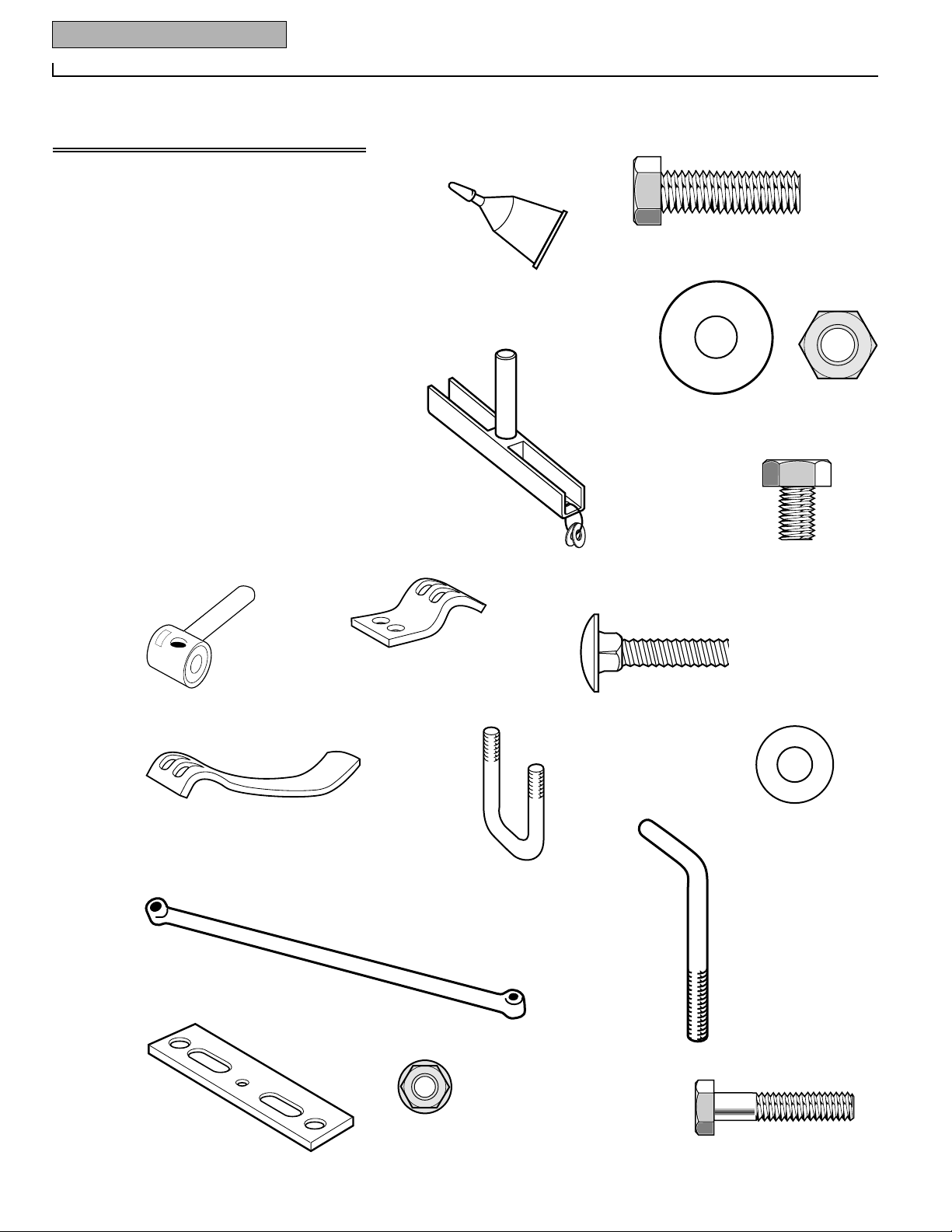
Ref. Description Qty.
11 Mounting Bracket (already installed).............1
12 Hex Flange Screw, 3/8"–16 x 1-1/4" long......3
13 Flat Washer, 3/8"...........................................3
14 Centerlock Nut, 3/8"–16................................3
15 Knife Head.....................................................1
16 Metric Hex Head Screw, M8 x M25...............2
17 Metric Internal Tooth Lockwasher, M8 .........2
18 Pitman Arm Assembly ..................................1
19 Shoe Holder..................................................2
20 Carriage Bolt, 5/16"–18 x 1"..........................4
21 Shoe..............................................................2
22 U-Bolt, 5/16" x 18..........................................2
23 Flat Washer, 5/16".........................................4
24 Weed Diverter...............................................1
25 Upper Hook ..................................................1
26 Doubler Plate................................................1
27 Flange Nut 1/4"– 20.......................................2
28 Flat Washer, 1/4"...........................................1
29 Hex Head Screw, 1/4"–20 x 1-1/4" long.........1
30 Battery Charger (optional - not shown).........1
31 Key (In Keyswitch) (optional - not shown)....1
18*
19*
21*
20
25
27
24*
22
23
26*
12
Ref. Description Qty.
11 Loctite®Thread Fastener, (bottle or tube)....1
12 Hex Cap Screw, 3/8"–16 x 1-1/4" (Grade 8) ..3
13 Flat Washer, hardened, 3/8"..........................3
14 Centerlock Nut, 3/8"–16................................3
15 Knife Head.....................................................1
16 Metric Hex Head Screw, M8 x M12...............2
-- Flat Washer, hardened, 5/16" (wire-tied to
knife head (Ref. 15) -- do not remove
until instructed to do so) ..........................2
18 Pitman Arm Assembly ..................................1
19 Shoe Holder..................................................2
20 Carriage Bolt, 5/16"–18 x 1"..........................4
21 Shoe..............................................................2
22 U-Bolt, 5/16" x 18..........................................2
23 Flat Washer, 5/16".........................................5
24 Weed Diverter...............................................1
25 Upper Hook ..................................................1
26 Doubler Plate................................................1
27 Flange Nut 1/4"– 20.......................................2
28 Hex Head Screw, 1/4"–20 x 1-1/4" ...............1
29 Battery Charger (optional - not shown).........1
30 Key (optional - not shown)...........................1
11
12
13
14
16
18*
19*
20
22
23
25
27
28
24*
26*
21*
15*

Section 2: Assembly 9
HANDLEBAR INSTALLATION
NOTE: Handlebar wiring from the operator presence controls (OPC) is connected
to a switch under the unit. DO NOT disconnect this wiring!
1. Before beginning assembly, disconnect
the spark plug wire from the spark plug.
2. Place the handlebars on the ground
behind the unit.
3. With the ends of the bridge (C,
Fig. 2-2) positioned as shown, insert the
bridge in between the handlebars into the
upper set of handlebar holes.
4. Align the holes in the plastic sleeves
(on the bottom ends of the handlebars)
with the corresponding handlebar holes in
the deck. For easier installation, apply a
small amount of oil to the sleeve ends.
5. Insert the bottom ends of the handlebars into their mounting brackets in the
deck (Fig. 2-3). Do not pinch or damage
the attached wiring. Align the screw holes
(it may be helpful to align the holes with a
punch or drift pin prior to installing the
screws in the next step).
NOTE: Position the handlebars with
thumb latches (F, Fig. 2-5) on the inner
sides of handlebars.
6. Secure each handlebar with a 5/16-18
x 2-1/4 hex head capscrew (A, Fig. 2-3)
and 5/16"-18 toplock nut (B).
NOTE: When correctly installed, the handlebars feel loose. The looseness or “play”
is intentionally designed to reduce vibration which occurs during operation. The
rubber sleeves on the handlebar ends act
as “shock absorbers” and also help reduce
vibration.
WHEEL DRIVE CONTROL ROD
INSTALLATION
1. Place the control rods (D, Fig. 2-4)
BETWEEN the handlebars and UNDER the
bridge, with the threaded ends down. For
easier installation, apply oil or grease to
the threads. Thread the rods into the
pivots (E) twelve turns each. If necessary,
use a screwdriver or a punch to move the
pivots into position. Be sure that the wire
harness on each handlebar is located to
the outside of each control rod.
2. Insert the upper end of each control
rod (G, Fig. 2-5) into the plastic thumb
latch (F) slots, then outward through the
holes in the wheel drive levers (H).
3. Insert hair pin clips (J, Fig. 2-5)
through the hole in each control rod. Position hair pin clips with loops up, as
shown.
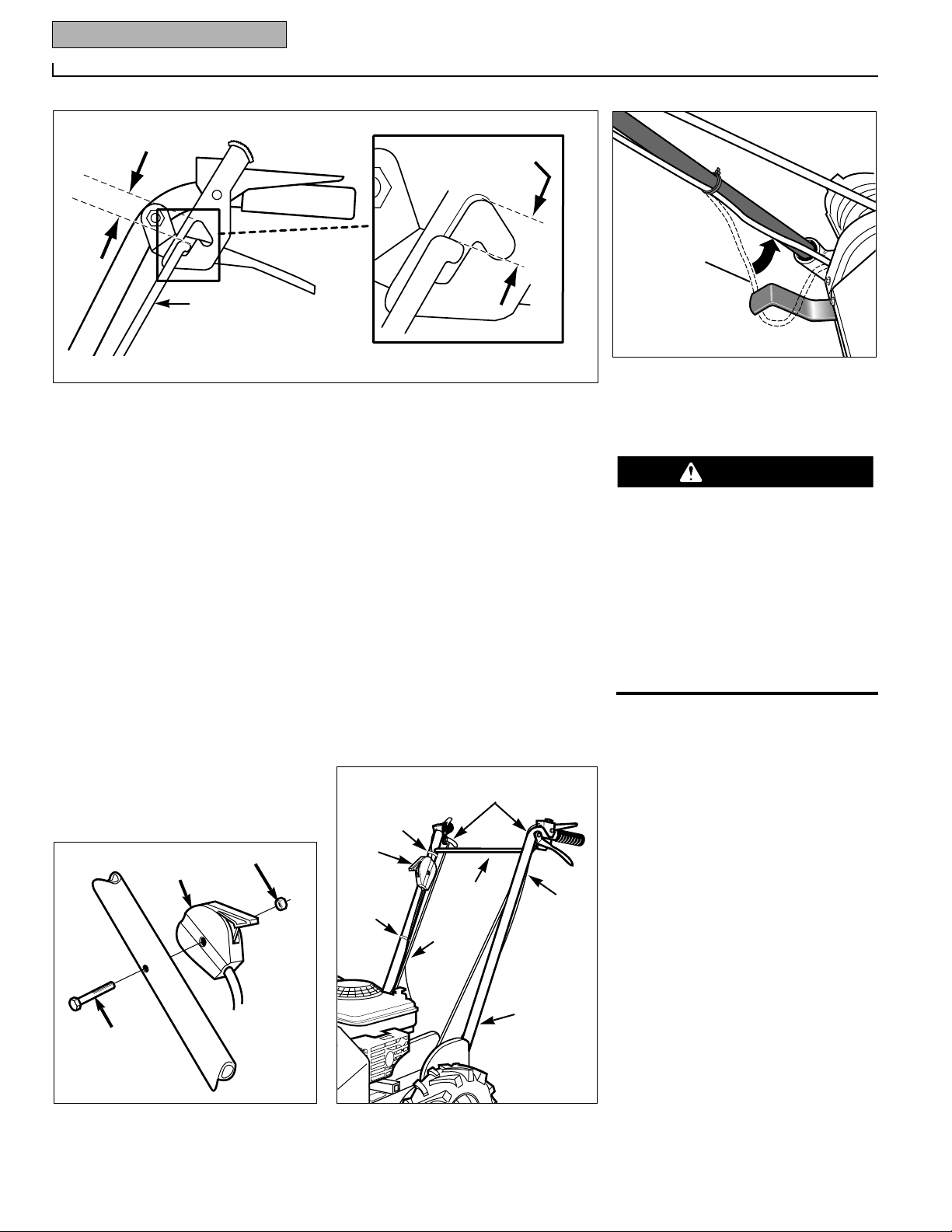
CONTROL ROD ADJUSTMENT
1. With the controls positioned as shown
(Fig. 2-6), measure the gap between the
top of the slot in the thumb latch bracket
and the control rod. Do not put any pressure on the handlebars when measuring.
The gap must measure 1-1/4" (32mm).
If adjustment is required, remove the hair
pin clip (J, Fig. 2-5) from the control rod.
Remove the control rod from the wheel
drive lever (H) and thumb latch (F). Turn
the control rod as needed to achieve the
1-1/4" (32mm) gap.
NOTE: Adjust the wheel drive control rods
properly. Improper adjustment will result
in broken thumb latches.
C
A
B
D
D
C
B
Install hair pins (D) OUTSIDE levers (C)
D
A
J on outside with loop up
Fig. 2-2
Fig. 2-3
Fig. 2-4
Fig. 2-5 Outer view of left handlebar
F
J
G
H
J
E
10 Section 2: Assembly
THROTTLE CONTROL LEVER
INSTALLATION
1. Unwind the throttle cable from around
the left side of the engine, then position
the throttle control lever (Z, Fig. 2-7) on
the inside of the right handlebar as shown
(Figs. 2-7 and 2-8). THE CABLE MUST BE
ROUTED UNDERNEATH THE CONTROL
ROD (see AA, Fig. 2-8).
2. Secure the throttle control lever to the
handlebar with a 1/4–20 x 2" hex-head
capscrew (A, Fig. 2-7) and 1/4"-20 locknut
(B). TO AVOID DAMAGING PLASTIC
ASSEMBLY, DO NOT OVER-TIGHTEN
SCREW AND LOCKNUT.
CABLE TIE INSTALLATION
Secure the throttle cable and OPC wiring
to the handlebars with cable ties (C, Fig.
2-8) to help prevent them from being
damaged during operation. Two of the
cable ties are already installed at the upper
end of the handlebars. Remove any slack
from the bottom of the OPC wires (see Fig.
2-8A) to avoid catching the cutter bar lever
on the wires. Twist the OPC wires (but not
the throttle cable) in a corkscrew pattern
along the length of the handlebars and
install the four cable ties (two on each
side). Cut off excess cable tie with scissors.
UNIT REMOVAL
Squeeze the four control levers on the
handlebars and carefully roll the unit from
off the shipping crate. Park the unit on a
flat, clean surface where you can complete
the remaining assembly steps.
CUTTER BAR ASSEMBLY
AND INSTALLATION
Cutter bar blades are extremely sharp!
To help avoid serious injury:
• When handling cutter bar, wear heavy
leather gloves and wrap cutter bar
with rags.
• Keep plastic guard on blade assembly
until you are ready to start engine.
• Contact with the blades will cause
serious personal injury.
Avoid contact with the cutter bar blades.
1. Remove the screws securing the cutter
bar to the crate. Wear heavy leather
gloves and wrap cutter bar with rags to
avoid cutting yourself on the blades.
2. Carefully remove the cutter bar from
the shipping crate. Keep the plastic blade
guard on the cutter bar to protect yourself
from injury.
IMPORTANT: To help prevent the unit
from tipping, have an assistant stand in
the operator position and firmly hold the
handlebars during installation of the cutter
bar.
3. REMOVE SPARK PLUG WIRE FROM
SPARK PLUG (IF ATTACHED).
4. Have an assistant available to hold the
unit firmly by the handlebars.
DANGER
B
A
(C) Already installed
1
1
/
4
" (32mm)
Gap here
(right side shown)
1
1
/
4
" (32mm)
A
C
C
C
Bridge
Fig. 2-6
Fig. 2-7
Fig. 2-8
Z
B
A
Z
C
AA
Fig. 2-8A
Remove
slack in wire
(on both
handlebars).

Section 2: Assembly 11
Disconnect the spark plug wire from the
spark plug before attempting to install
the cutter bar. Move the spark plug wire
away from the spark plug and prevent the
wire from contacting the plug.
5. Center eccentric arm (A, Fig. 2-14), if
necessary, by moving cutter bar lever to
ON (Fig. 2-15) and pulling starter rope.
6. Position the cutter bar (B, Fig. 2-9) at
the front of the cutter bar mounting
bracket (C) as shown. Place the doubler
bracket (D) on the cutter bar and align the
three mounting holes as shown.
7. Apply a small amount of Loctite®
Thread Fastener (use only a small amount,
as a total of five screws need to be coated
during the assembly procedure) to the
threads of the three 3/8-16 x 1-1/4 hex
cap screws (E, Fig. 2-9). Have an assistant
hold the unit firmly by the handlebars and
raise the front of the unit a few inches off
the ground. Securely attach the cutter bar
and doubler bracket to the cutter bar
mounting bracket with the three hex cap
screws (E), 3/8 flat washers (F) and 3/816 center locknuts (G). Torque to 35 ftlbs. if you have a torque wrench. Lower
the unit to the ground.
IMPORTANT: Allow the Loctite® to cure
for at least one hour (preferably 24 hours
at 72oF.) before operating unit.
8. Align the middle hole (B, Fig. 2-10) in
the cutter bar with the middle locknut (CC,
Fig. 2-10) on the cutter mounting bracket.
If needed, tap the ends of the cutting blade
back and forth (see inset, Fig. 2-10) to
align the middle hole (use a wood block to
avoid damaging the blade).
9. Slide the pitman assembly (H, Fig. 210A-1) onto the post of the knife head (I).
The “Top” decal on the pitman assembly
must be facing up. Remove the two 5/16
hardened flat washers that are wire-tied to
the knife head for shipping purposes.
CAUTION
Fig. 2-9
B
E
G
F
C
D
J
Fig. 2-10
Fig. 2-10A
B
CC
Tap top section of
cutting blade from
side-to-side to
align middle hole
(B) with middle
locknut (CC).
H
I
1
2
3
4
L
K
 Loading...