


TL-ER5120
Table of contents
 Loading...
TL-ER5120
Gigabit Load Balance Broadband Router
Rev: 1.0.0
1910010517

COPYRIGHT & TRADEMARKS
Specifications are subject to change without notice. is a registered trademark of
TP-LINK TECHNOLOGIES CO., LTD. Other brands and product names are trademarks of their
respective holders.
No part of the specifications may be reproduced in any form or by any means or used to make any
derivative such as translation, transformation, or adaptation without permission from TP-LINK
TECHNOLOGIES CO., LTD. Copyright © 2011 TP-LINK TECHNOLOGIES CO., LTD. All rights
reserved.
http://www.tp-link.com
FCC STATEMENT
This equipment has been tested and found to comply with the limits for a Class A digital device,
pursuant to part 15 of the FCC Rules. These limits are designed to provide reasonable protection
against harmful interference when the equipment is operated in a commercial environment. This
equipment generates, uses, and can radiate radio frequency energy and, if not installed and used in
accordance with the instruction manual, may cause harmful interference to radio communications.
Operation of this equipment in a residential area is likely to cause harmful interference in which case
the user will be required to correct the interference at his own expense.
This device complies with part 15 of the FCC Rules. Operation is subject to the following two
conditions:
1) This device may not cause harmful interference.
2) This device must accept any interference received, including interference that may cause
undesired operation.
Any changes or modifications not expressly approved by the party responsible for compliance could
void the user’s authority to operate the equipment.
CE Mark Warning
This is a class A product. In a domestic environment, this product may cause radio interference, in
which case the user may be required to take adequate measures.
-I-

CONTENTS
Package Contents..................................................................................................................1
Chapter 1 About this Guide
1.1 Intended Readers ..................................................................................................................2
1.2 Conventions ...........................................................................................................................2
1.3 Overview of this Guide...........................................................................................................2
Chapter 2 Introduction
2.1 Overview of the Router ..........................................................................................................4
2.2 Features.................................................................................................................................5
2.3 Appearance............................................................................................................................6
2.3.1 Front Panel ................................................................................................................6
2.3.2 Rear Panel.................................................................................................................7
Chapter 3 Configuration
3.1 Network..................................................................................................................................9
...................................................................................................2
..........................................................................................................4
........................................................................................................9
3.1.1 Status.........................................................................................................................9
3.1.2 System Mode...........................................................................................................10
3.1.3 WAN ........................................................................................................................13
3.1.4 LAN..........................................................................................................................31
3.1.5 DMZ.........................................................................................................................35
3.1.6 MAC Address...........................................................................................................36
3.1.7 Switch ......................................................................................................................38
3.2 User Group ..........................................................................................................................44
3.2.1 Group.......................................................................................................................45
3.2.2 User .........................................................................................................................45
3.2.3 View .........................................................................................................................46
3.3 Advanced .............................................................................................................................47
3.3.1 NAT..........................................................................................................................47
3.3.2 Traffic Control ..........................................................................................................55
-II-

3.3.3 Session Limit ...........................................................................................................59
3.3.4 Load Balance...........................................................................................................60
3.3.5 Routing ....................................................................................................................65
3.4 Firewall.................................................................................................................................70
3.4.1 Anti ARP Spoofing ...................................................................................................70
3.4.2 Attack Defense ........................................................................................................73
3.4.3 MAC Filtering ...........................................................................................................75
3.4.4 Access Control.........................................................................................................76
3.4.5 App Control..............................................................................................................82
3.5 Services ...............................................................................................................................84
3.5.1 PPPoE Server..........................................................................................................84
3.5.2 E-Bulletin .................................................................................................................90
3.5.3 Dynamic DNS ..........................................................................................................92
3.5.4 UPnP .......................................................................................................................97
3.6 Maintenance ........................................................................................................................98
3.6.1 Admin Setup ............................................................................................................98
3.6.2 Management..........................................................................................................101
3.6.3 Statistics.................................................................................................................103
3.6.4 Diagnostics ............................................................................................................105
3.6.5 Time.......................................................................................................................108
3.6.6 Logs.......................................................................................................................109
Chapter 4 Application
4.1 Network Requirements....................................................................................................... 111
........................................................................................................ 111
4.2 Configurations.................................................................................................................... 111
4.2.1 Internet Setting ...................................................................................................... 111
4.2.2 Network Management............................................................................................ 114
4.2.3 Network Security....................................................................................................118
Chapter 5 CLI….
................................................................................................................124
-III-

5.1 Configuration......................................................................................................................124
5.2 Interface Mode ...................................................................................................................127
5.3 Online Help ........................................................................................................................128
5.4 Command Introduction.......................................................................................................129
5.4.1 ip............................................................................................................................130
5.4.2 ip-mac....................................................................................................................130
5.4.3 sys .........................................................................................................................130
5.4.4 user........................................................................................................................132
5.4.5 history ....................................................................................................................133
5.4.6 exit .........................................................................................................................134
Appendix A Hardware Specifications
Appendix B FAQ
Appendix C Glossary
.........................................................................................................136
..................................................................................................138
...........................................................................135
-IV-

Package Contents
The following items should be found in your box:
¾ One TL-ER5120 Router
¾ One power cord
¾ One console cable
¾ Two mounting brackets and other fittings
¾ Installation Guide
¾ Resource CD for TL-ER5120 Router, including:
• This User Guide
• Other Helpful Information
Note:
Make sure that the package contains the above items. If any of the listed items are damaged or
missing, please contact with your distributor.
-1-
Chapter 1 About this Guide
This User Guide contains information for setup and management of TL-ER5120 Router. Please read
this guide carefully before operation.
1.1 Intended Readers
This Guide is intended for Network Engineer and Network Administrator.
1.2 Conventions
In this Guide the following conventions are used:
¾ The Router or TL-ER5120 mentioned in this Guide stands for TL-ER5120 Gigabit Load Balance
Broadband Router without any explanation.
¾ Menu Name→Submenu Name→Tab page indicates the menu structure. Advanced→NAT
→Basic NAT means the Basic NAT page under the NAT menu option that is located under the
Advanced menu.
¾ Bold font indicates a toolbar icon, menu or menu item.
¾ <Font> indicate a button.
Symbols in this Guide:
Symbol Description
Ignoring this type of note might result in a malfunction or damage to the
Note:
Tips:
device.
This format indicates important information that helps you make better use of
your device.
1.3 Overview of this Guide
Chapter 1 About This Guide Introduces the guide structure and conventions.
Chapter 2 Introduction Introduces the features and appearance of TL-ER5120 router.
Chapter 3 Configurations Introduces how to configure the Router via Web management page.
Chapter 4 Application Introduces the practical application of the Router on the enterprise
network.
Chapter5 CLI Introduces how to log in and set up the Router using CLI commands by
console port.
-2-

Appendix A Hardware
Lists the hardware specifications of this Router.
Specifications
Appendix B FAQ Provides the possible solutions to the problems that may occur during
the installation and operation of the router.
Appendix C Glossary Lists the glossary used in this guide.
-3-

Chapter 2 Introduction
Thanks for choosing the Gigabit Load Balance Broadband Router TL-ER5120.
2.1 Overview of the Router
The Gigabit Load Balance Broadband Router TL-ER5120 from TP-LINK possesses excellent data
processing capability and multiple powerful functions including Load Balance, Access Control,
Bandwidth Control, Session Limit, IM/P2P Blocking, PPPoE Server and so on, which consumedly
meet the needs of small and medium enterprise, hotels and communities with volumes of users
demanding a efficient and easy-to-manage network with high security.
z Powerful Data Processing Capability
+ Built-in MIPS64 network processor and 128MB DDRII high-speed RAM allows the stability and
reliability for operation.
z Online Behavior Management
+ Complete Functions of Access Rules can allow managers to select the network service levels to
block or allow applications of FTP downloading, Email, Web browsing and so on.
+ Deploying One-Click restricting of IM/P2P applications to save time & energy while reserving
exceptional groups for certain users.
+ Supporting URL Filtering to prevent potential hazards from visiting the malicious Web sites.
z Powerful Firewall
+ Supporting One-Click IP-MAC Binding to avoid ARP spoofing and guarantee a network without
stagnation.
+ Featured Attack Defense to protect the network from a variety of flood attack and packet
anomaly attack.
+ Possessing MAC Filtering function to block the access of illegal hosts.
z Flexible Traffic Control
+ Featured Bandwidth Control with flexible bandwidth management to automatically control the
bandwidth of the host in bi-direction to avoid bandwidth over occupation, as well as optimize
bandwidth usage.
+ Supporting Session Limit to avoid the complaint of a few people to force whole sessions.
z Multi-WAN Ports
+ Providing three adjustable 10/100/1000M WAN/LAN ports for users to configure the amount of
WAN ports based on need and connect multiple Internet lines for bandwidth expansion.
+ Supporting multiple Load Balance modes, including Bandwidth Based Balance Routing,
Application Optimized Routing, and Policy Routing to optimize bandwidth usage.
-4-

+ Featured Link Backup to switch all the new sessions from dropped line automatically to another
for keeping an always on-line network.
z Easy-to-use
+ Providing easy-to-use GUI with clear configuration steps and detailed help information for the
users to configure the Router simply.
+ Helping administrators to monitor the whole network status and take actions to malfunctions
according to the recorded log information.
+ Supporting remote management to manage the Router from remote places.
2.2 Features
Hardware
¾ Embedded with MIPS64 network processor with frequency of 500MHz
¾ Equipped with 128MB DDRII high-speed RAM
¾ 1 fixed gigabit WAN port (port 1), 3 adjustable gigabit WAN/LAN ports, 1 LAN/DMZ port (port 5)
and 1 Console port
¾ Built-in high-quality power supply with non-fun system design for quietness
¾ Possesses standard-sized, 19-inch outfit for standard rack
¾ Supports Professional 4kV common mode
¾ Complies with IEEE 802.3、IEEE 802.3u standards
¾ Supports TCP/IP,DHCP,ICMP,NAT,NAPT protocols
¾ Supports PPPoE,SNTP,HTTP,DDNS、UPnP,NTP protocols
Basic Functions
¾ Supports Static IP, Dynamic IP, PPPoE/Russian PPPoE, L2TP/Russian L2TP, PPTP/Russian
PPTP, Dual Access, BigPond Internet connections
¾ Supports Virtual Server, Port Triggering, ALG, Static Route and RIP v1/v2
lightning protection
¾ Built-in Switch supporting Port Mirror, Port VLAN, Rate Control and so on
¾ Supports to change the MAC address of LAN, WAN, DMZ port
¾ Supports Logs, Statistics, Time setting
¾ Supports Remote and Web management
¾ Supports Diagnostic (Ping/Tracert) and Online Detection
Traffic Control
-5-
¾ Supports Bandwidth Control
¾ Supports Session Limit
Security
¾ Built-in firewall supporting URL/MAC Filtering
¾ Supports Access Control
¾ Supports Attack Defense
¾ Supports IP-MAC Binding
¾ Supports GARP (Gratuitous ARP)
¾ Deploys One-Click restricting of IM/P2P applications
2.3 Appearance
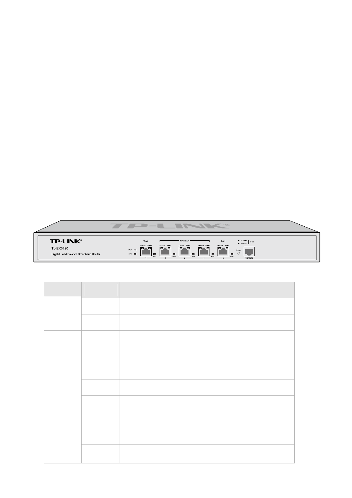
2.3.1 Front Panel
The front panel of TL-ER5120 is shown as the following figure.
z
LEDs
LED Status Indication
On The Router is powered on
PWR
Off The Router is powered off or power supply is abnormal
Flashing The Router works properly
SYS
On/Off The Router works improperly
On There is a device linked to the corresponding port
Link/Act
Speed
Off There is no device linked to the corresponding port
Flashing The corresponding port is transmitting or receiving data
On (Green) The linked device is running at 1000Mbps
On (Yellow) The linked device is running at 100Mbps
Off
There is no device linked to the corresponding port or the
-6-
On The port is working in WAN mode
WAN
Off The port is working in LAN mode
On The port is working in DMZ mode
DMZ
Off The port is working in LAN mode
z
Interface Description
Interface Port Description
linked device is running at 10Mbps
WAN 1~4
LAN 2~5
The WAN port is for connecting the Router to a DSL/Cable
modem or Ethernet by the RJ45 cable
The LAN port is for connecting the Router to the local PCs or
switches by the RJ45 cable
DMZ 5 The DMZ port is for connecting the Router to the servers
Console /
z
Reset button
The Console port is for connecting with the serial port of a
computer or terminal to monitor and configure the Router
Use the button to restore the Router to the factory defaults. With the Router powered on, use a pin to
press and hold the Reset button (about 4~5 seconds). After the SYS LED goes out, release the Reset
button. If the SYS LED is flashing with a high frequency about two or three seconds, it means the Router
is restored successfully.
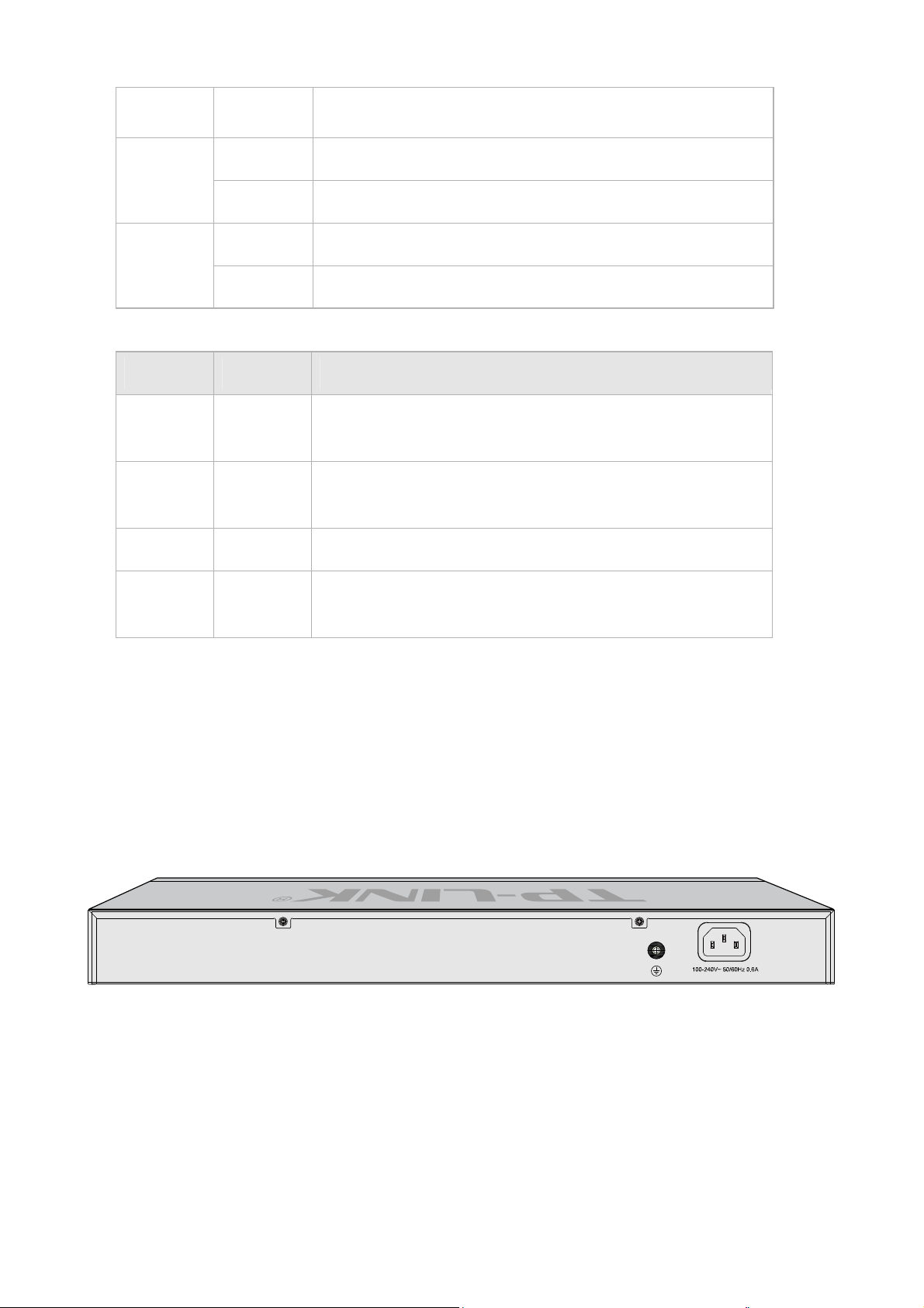
2.3.2 Rear Panel
The rear panel of TL-ER5120 is shown as the following figure.
z
Power Socket
Connect the female connector of the power cord to this power socket, and the male connector to the AC
power outlet. Please make sure the voltage of the power supply meets the requirement of the input
voltage (100-240V~ 50/60Hz).
z
Grounding Terminal
The Router already comes with lightning protection mechanism. You can also ground the Router through
the PE (Protecting Earth) cable of AC cord or with Ground Cable.
-7-

Note:
Please use only the power cord provided with this Router.
-8-

Chapter 3 Configuration
3.1 Network
3.1.1 Status
The Status page shows the system information, the port connection status and other information
related to this Router.
Choose the menu Network→Status to load the following page.
-9-
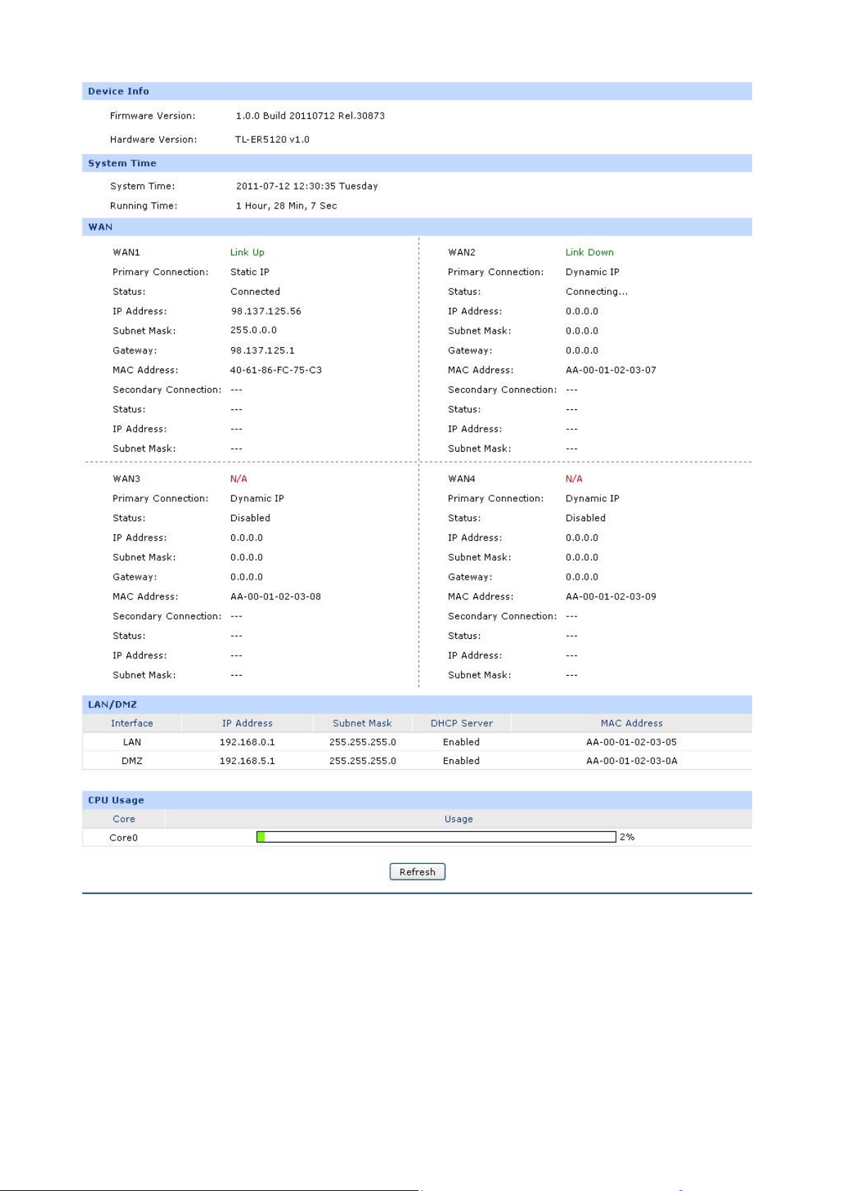
Figure 3-1 Status
3.1.2 System Mode
The TL-ER5120 Router can work in three modes: NAT, Non-NAT and Classic.
If your Router is hosting your local network’s connection to the Internet with a network topology as the
Figure 3-2 shown, you can set it to NAT mode.
-10-
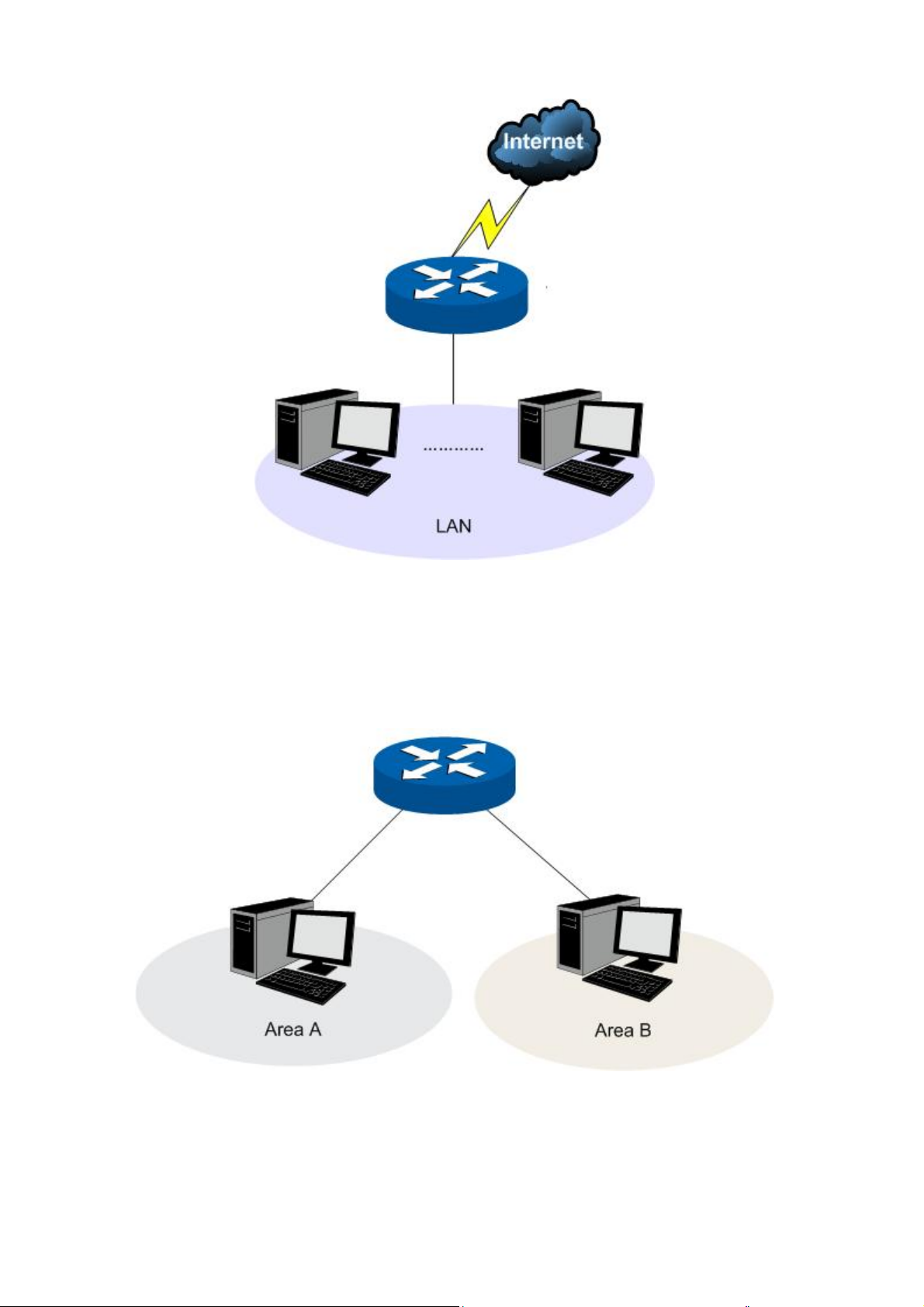
Figure 3-2 Network Topology - NAT Mode
If your Router is connecting the two networks of different areas in a large network environment with a
network topology as the Figure 3-3 shown, and forwards the packets between these two networks by
the Routing rules, you can set it to Non-NAT mode.
Figure 3-3 Network Topology – Non-NAT Mode
If your Router is connected in a combined network topology as the Figure 3-4 shown, you can set it to
Classic Mode.
-11-
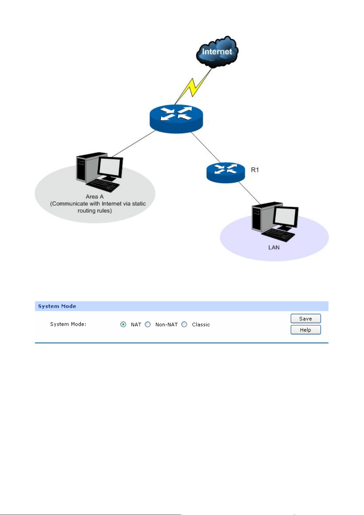
Figure 3-4 Network Topology – Classic Mode
Choose the menu Network→System Mode to load the following page.
Figure 3-5 System Mode
You can select a System Mode for your Router according to your network need.
z NAT Mode
NAT (Network Address Translation) mode allows the Router to translate private IP addresses within
internal networks to public IP addresses for traffic transport over external networks, such as the
Internet. Incoming traffic is translated back for delivery within the internal network. However, the
Router will drop all the packets whose source IP addresses are in different subnet of LAN port. For
example: If the LAN port of the Router is set to 192.168.0.1 for IP address and 255.255.255.0 for the
Subnet Mask, then the subnet of LAN port is 192.168.0.0/24. The packet with 192.168.0.123 as its
-12-
source IP address can be transported by NAT, whereas the packet with 20.31.76.80 as its source IP
address will be dropped.
z Non-NAT Mode
In this mode, the Router functions as the traditional Gateway and forwards the packets via routing
protocol. The Hosts in different subnets can communicate with one another via the routing rules
whereas no NAT is employed. For example: If the DMZ port of the Router is in WAN mode, the Hosts
in the subnet of DMZ port can access the servers in Internet only when the Static Router rules permit.
Note:
In Non-NAT mode, all the NAT forwarding rules will be disabled.
z Classic Mode
It's the combined mode of NAT mode and Non-NAT mode. In Classic mode, the Router will first
transport the packets which are compliant with NAT forwarding rules and then match the other packets
to the static routing rules. The matched packets will be transmitted based on the static routing rules
and the unmatched ones will be dropped. In this way, the Router can implement NAT for the packets
without blocking the packets in the different subnet of the ports.
3.1.3 WAN
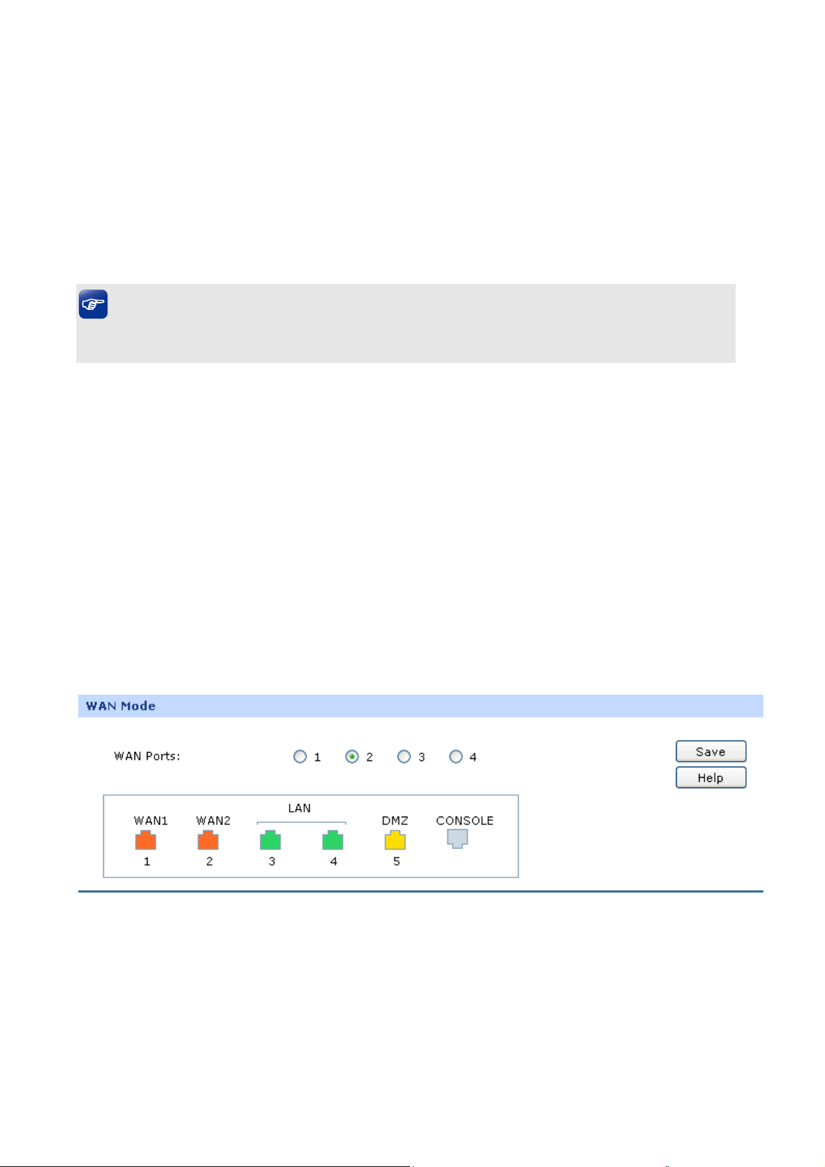
3.1.3.1 WAN Mode
TL-ER5120 provides four available WAN ports. You can set the number of WAN ports on this page.
Choose the menu Network→WAN→WAN Mode to load the following page.
¾ WAN Mode
WAN Ports:
Figure 3-6 WAN Mode
Select the total number of WAN ports you prefer to use.
And the Router will adjust the physical ports
accordingly, which can be illustrated on the following
-13-

port sketch.
Note:
1) By default, TL-ER5120 is set to work in the mode of dual WAN ports.
2) Any change to the number of WAN ports may lead to a loss of current configurations. Please be
sure to backup your configurations in advance.
3) The DMZ port will not be available if four WAN ports are enabled.
3.1.3.2 WAN1
TL-ER5120 provides the following six Internet connection types: Static IP, Dynamic IP, PPPoE/Russian
PPPoE, L2TP/Russian L2TP, PPTP/Russian PPTP and BigPond. To configure the WAN, please first
select the type of Internet connection provided by your ISP (Internet Service Provider).
Tips:
● It’s allowed to set the IP addresses of multiple WAN ports within the same subnet. However, to
guarantee a normal communication, make sure that the WAN ports can access the same network,
such as Internet or a local area network.
● The amount of tab pages for WAN port varies with the number of the WAN ports. For the
configurations of the other WAN ports, please refer to the instructions of WAN1.
Choose the menu Network→WAN→WA N1 to load the configuration page.
1) Static IP
If a static IP address has been provided by your ISP, please choose the Static IP connection type to
configure the parameters for WAN port manually.
-14-
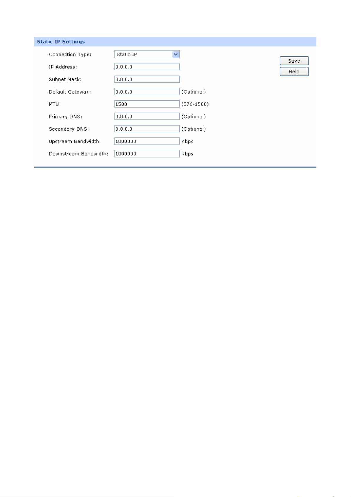
Figure 3-7 WAN – Static IP
The following items are displayed on this screen:
¾ Static IP
Connection Type:
IP Address:
Subnet Mask:
Default Gateway:
MTU:
Select Static IP if your ISP has assigned a static IP
address for your computer.
Enter the IP address assigned by your ISP. If you are
not clear, please consult your ISP.
Enter the Subnet Mask assigned by your ISP.
Optional. Enter the Gateway assigned by your ISP.
MTU (Maximum Transmission Unit) is the maximum
data unit transmitted by the physical network. It can be
set in the range of 576-1500. The default MTU is 1500.
It is recommended to keep the default value if no other
MTU value is provided by your ISP.
Primary DNS:
Enter the IP address of your ISP’s Primary DNS
(Domain Name Server). If you are not clear, please
consult your ISP. It’s not allowed to access the Internet
via domain name if the Primary DNS field is blank.
-15-
Secondary DNS:
Optional. If a Secondary DNS Server address is
available, enter it.
Upstream Bandwidth:
Specify the bandwidth for transmitting packets on the
port.
Downstream
Specify the bandwidth for receiving packets on the port.
Bandwidth:
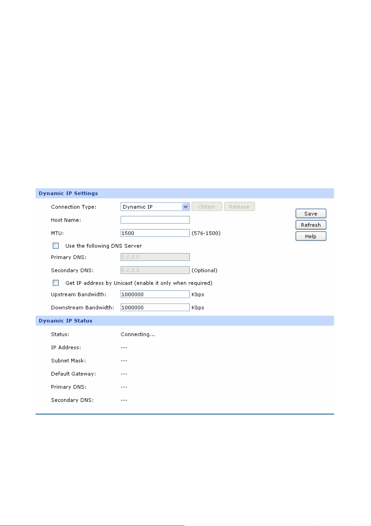
2) Dynamic IP
If your ISP (Internet Service Provider) assigns the IP address automatically, please choose the
Dynamic IP connection type to obtain the parameters for WAN port automatically.
Figure 3-8 WAN – Dynamic IP
The following items are displayed on this screen:
¾ Dynamic IP
-16-

Connection Type:
Host Name:
MTU:
Get IP Address by
Unicast:
Select Dynamic IP if your ISP assigns the IP address
automatically. Click <Obtain> to get the IP address
from your ISP’s server. Click <Release> to release the
current IP address of WAN port.
Optional. This field allows you to give a name for the
Router. It's blank by default.
MTU (Maximum Transmission Unit) is the maximum
data unit transmitted by the physical network. It can
be set in the range of 576-1500. The default MTU is
1500. It is recommended to keep the default value if
no other MTU value is provided by your ISP.
The broadcast requirement may not be supported by
a few ISPs. Select this option if you can not get the IP
address from your ISP even with a normal network
Use the following DNS
Server:
Primary DNS:
Secondary DNS:
Upstream Bandwidth:
Downstream
Bandwidth:
connection. This option is not required generally.
Select this option to enter the DNS (Domain Name
Server) address manually.
Enter the IP address of your ISP’s Primary DNS
(Domain Name Server). If you are not clear, please
consult your ISP.
Optional. If a Secondary DNS Server address is
available, enter it.
Specify the bandwidth for transmitting packets on the
port.
Specify the bandwidth for receiving packets on the
port.
¾ Dynamic IP Status
Status:
Displays the status of obtaining an IP address from
-17-

your ISP.
z “Disabled” indicates that the Dynamic IP
connection type is not applied.
z “Connecting” indicates that the Router is
obtaining the IP parameters from your ISP.
z “Connected” indicates that the Router has
successfully obtained the IP parameters from
your ISP.
z “Disconnected” indicates that the IP address has
been manually released or the request of the
Router gets no response from your ISP. Please
check your network connection and consult your
ISP if this problem remains.
IP Address:
Subnet Mask:
Gateway Address:
Primary DNS:
Secondary DNS:
Displays the IP address assigned by your ISP.
Displays the Subnet Mask assigned by your ISP.
Displays the Gateway Address assigned by your ISP.
Displays the IP address of your ISP’s Primary DNS.
Displays the IP address of your ISP’s Secondary
DNS.
3) PPPoE
If your ISP (Internet Service Provider) has provided the account information for the PPPoE connection,
please choose the PPPoE connection type (Used mainly for DSL Internet service).
-18-
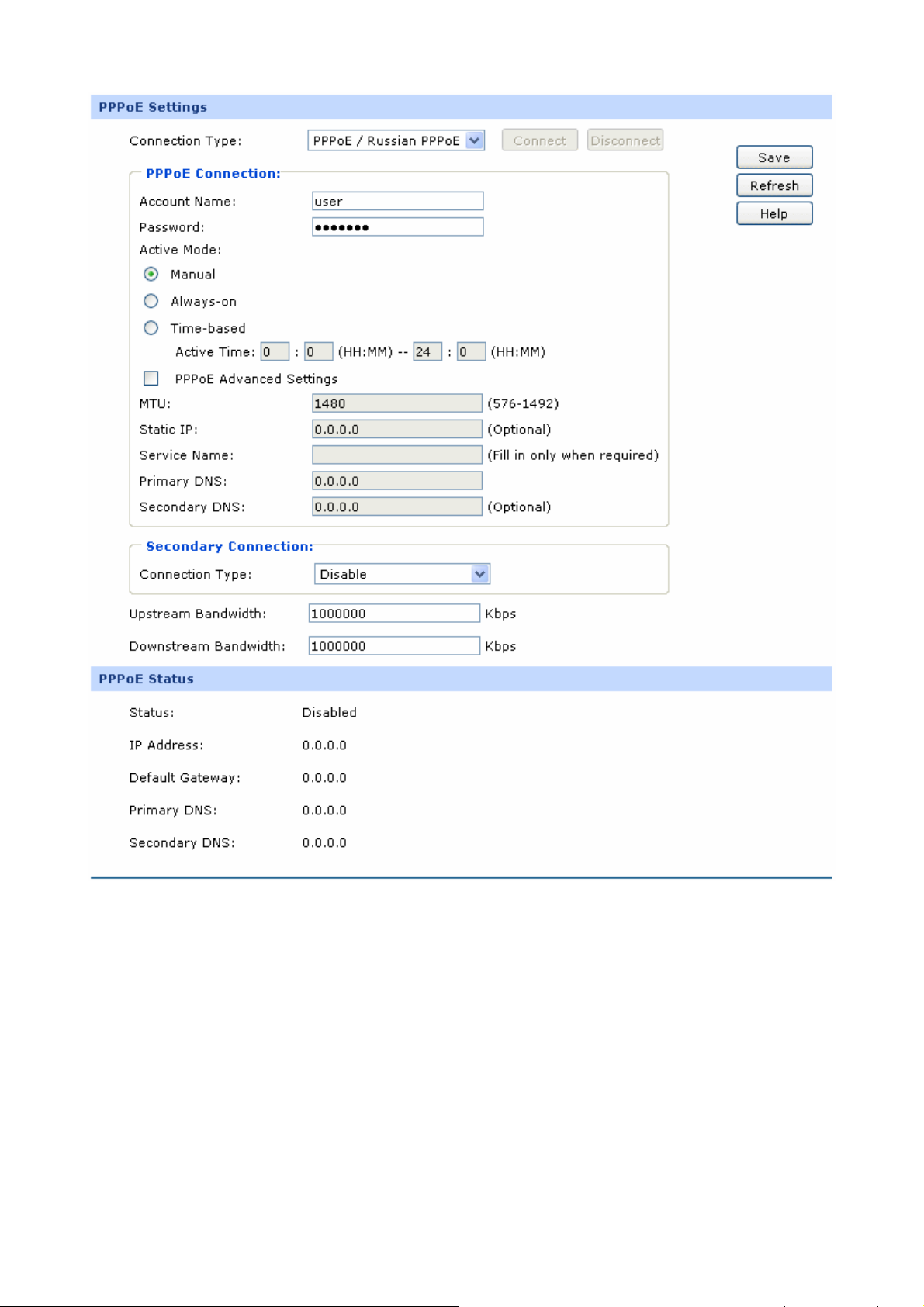
Figure 3-9 WAN - PPPoE
The following items are displayed on this screen:
¾ PPPoE Settings
Connection Type:
Select PPPoE if your ISP provides xDSL Virtual
Dial-up connection. Click <Connect> to dial-up to the
Internet and obtain the IP address. Click
<Disconnect> to disconnect the Internet connection
and release the current IP address.
-19-

Account Name:
Password:
Active Mode:
Enter the Account Name provided by your ISP. If you
are not clear, please consult your ISP.
Enter the Password provided by your ISP.
You can select the proper Active mode according to
your need.
z Manual: Select this option to manually activate or
terminate the Internet connection by the
<Connect> or <Disconnect> button. It’s optimum
for the dial-up connection charged on time.
z Always-on: Select this option to keep the
connection always on. The connection can be
re-established automatically when it is down.
z Time-based: Select this option to keep the
connection on during the Active time you set.
PPPoE Advanced
Check here to enable PPPoE advanced settings.
Settings:
MTU:
MTU (Maximum Transmission Unit) is the maximum
data unit transmitted by the physical network. It can
be set in the range of 576-1492. The default MTU is
1480. It is recommended to keep the default value if
no other MTU value is provided by your ISP.
ISP Address:
Optional. Enter the ISP address provided by your ISP.
It's null by default.
Service Name:
Optional. Enter the Service Name provided by your
ISP. It's null by default.
Primary DNS:
Secondary DNS:
Secondary Connection:
Enter the IP address of your ISP’s Primary DNS.
Optional. Enter the IP address of your ISP’s
Secondary DNS.
Here allows you to configure the secondary
-20-

connection. Dynamic IP and Static IP connection
types are provided.
Connection Type:
IP Address:
Subnet Address:
Status:
Upstream Bandwidth:
Downstream Bandwidth:
Select the secondary connection type. Options
include Disable, Dynamic IP and Static IP.
If Static IP is selected, configure the IP address of
WAN port. If Dynamic IP is selected, the obtained IP
address of WAN port is displayed.
If Static IP is selected, configure the subnet address of
WAN port. If Dynamic IP is selected, the obtained
subnet address of WAN port is displayed.
Displays the status of secondary connection.
Specify the bandwidth for transmitting packets on the
port.
Specify the bandwidth for receiving packets on the
¾ PPPoE Status
Status:
port.
Displays the status of PPPoE connection.
z “Disabled” indicates that the PPPoE connection
type is not applied.
z “Connecting” indicates that the Router is
obtaining the IP parameters from your ISP.
z “Connected” indicates that the Router has
successfully obtained the IP parameters from
your ISP.
z “Disconnected” indicates that the connection has
been manually terminated or the request of the
Router has no response from your ISP. Please
ensure that your settings are correct and your
network is connected well. Consult your ISP if
-21-

this problem remains.
IP Address:
Gateway Address:
Primary DNS:
Secondary DNS:
Displays the IP address assigned by your ISP.
Displays the Gateway Address assigned by your ISP.
Displays the IP address of your ISP’s Primary DNS.
Displays the IP address of your ISP’s Secondary
DNS.
4) L2TP
If your ISP (Internet Service Provider) has provided the account information for the L2TP connection,
please choose the L2TP connection type.
-22-
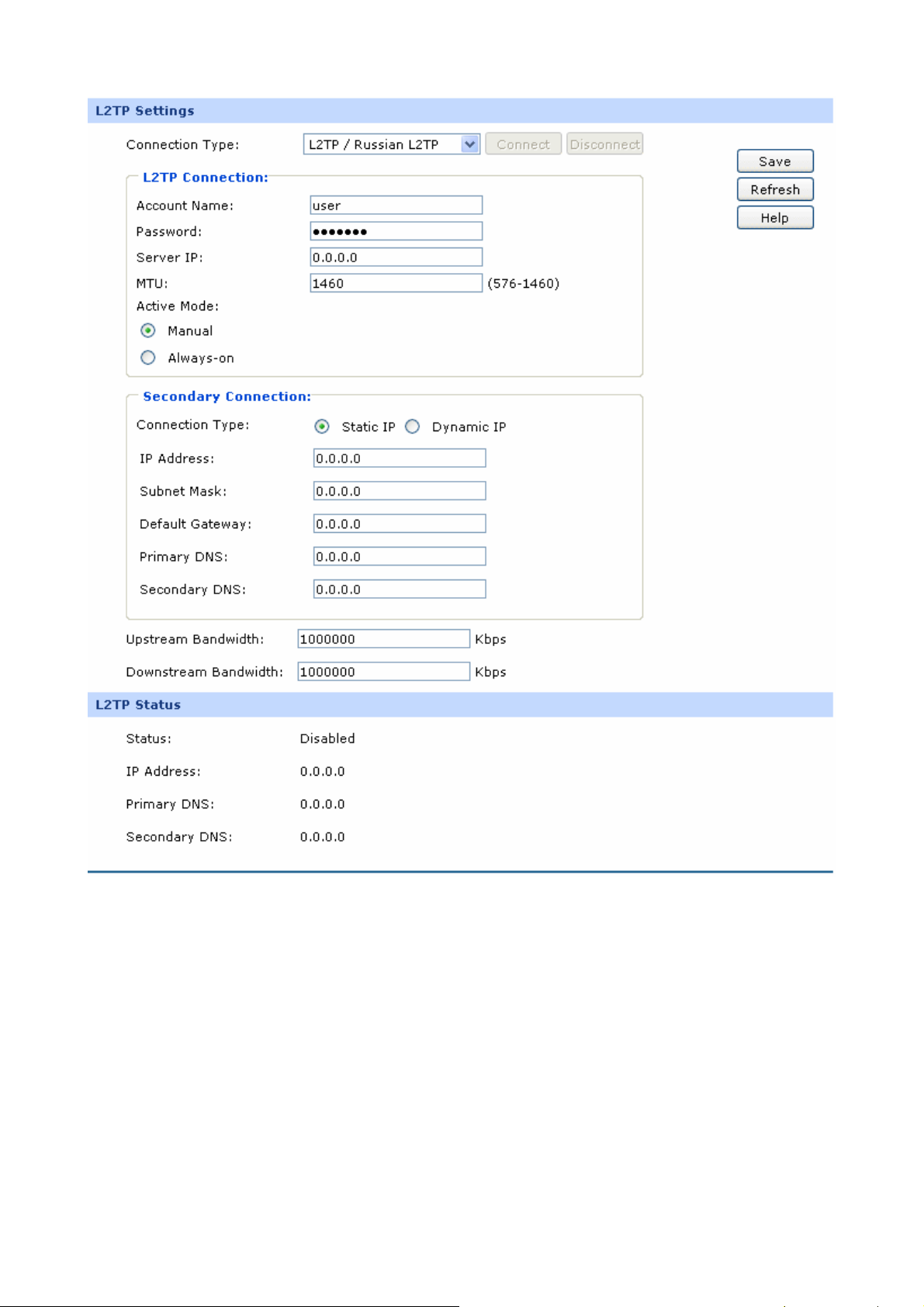
Figure 3-10 WAN - L2TP
The following items are displayed on this screen:
¾ L2TP Settings
Connection Type:
Select L2TP if your ISP provides a L2TP connection.
Click <Connect> to dial-up to the Internet and obtain the
IP address. Click <Disconnect> to disconnect the Internet
connection and release the current IP address.
Account Name:
Enter the Account Name provided by your ISP. If you are
-23-

not clear, please consult your ISP.
Password:
Server IP:
MTU:
Active Mode:
Enter the Password provided by your ISP.
Enter the Server IP provided by your ISP.
MTU (Maximum Transmission Unit) is the maximum data
unit transmitted by the physical network. It can be set in
the range of 576-1460. The default MTU is 1460. It is
recommended to keep the default value if no other MTU
value is provided by your ISP.
You can select the proper Active Mode according to your
need.
z Manual: Select this option to manually activate or
terminate the Internet connection by the <Connect>
or <Disconnect> button. It’s optimum for the dial-up
connection charged on time.
Secondary
Connections:
Connection Type:
IP Address:
Subnet Mask:
z Always-on: Select this option to keep the connection
always on. The connection can be re-established
automatically when it is down.
Here allows you to configure the secondary connection.
Dynamic IP and Static IP connection types are provided.
Select the secondary connection type. Options include
Disable, Dynamic IP and Static IP.
If Static IP is selected, configure the IP address of WAN
port. If Dynamic IP is selected, the IP address of WAN
port obtained is displayed.
If Static IP is selected, configure the subnet mask of WAN
port. If Dynamic IP is select, the subnet mask of WAN
port obtained is displayed.
Default Gateway:
If Static IP is selected, configure the default gateway. If
Dynamic IP is selected, the obtained default gateway is
displayed.
-24-

Primary
DNS/Secondary DNS:
Upstream
Bandwidth:
Downstream
Bandwidth:
¾ L2TP Status
Status:
If Static IP is selected, configure the DNS. If Dynamic IP
is selected, the obtained DNS is displayed.
Specify the bandwidth for transmitting packets on the
port.
Specify the bandwidth for receiving packets on the port.
Displays the status of PPPoE connection.
z “Disabled” indicates that the L2TP connection type is
not applied.
z “Connecting” indicates that the Router is obtaining
IP Address:
Primary DNS:
Secondary DNS:
the IP parameters from your ISP.
z “Connected” indicates that the Router has
successfully obtained the IP parameters from your
ISP.
z “Disconnected” indicates that the connection has
been manually terminated or the request of the
Router has no response from your ISP. Please
ensure that your settings are correct and your
network is connected well. Consult your ISP if this
problem remains.
Displays the IP address assigned by your ISP.
Displays the IP address of your ISP’s Primary DNS.
Displays the IP address of your ISP’s Secondary DNS.
5) PPTP
If your ISP (Internet Service Provider) has provided the account information for the PPTP connection,
please choose the PPTP connection type.
-25-
Loading...