

Page 1
1
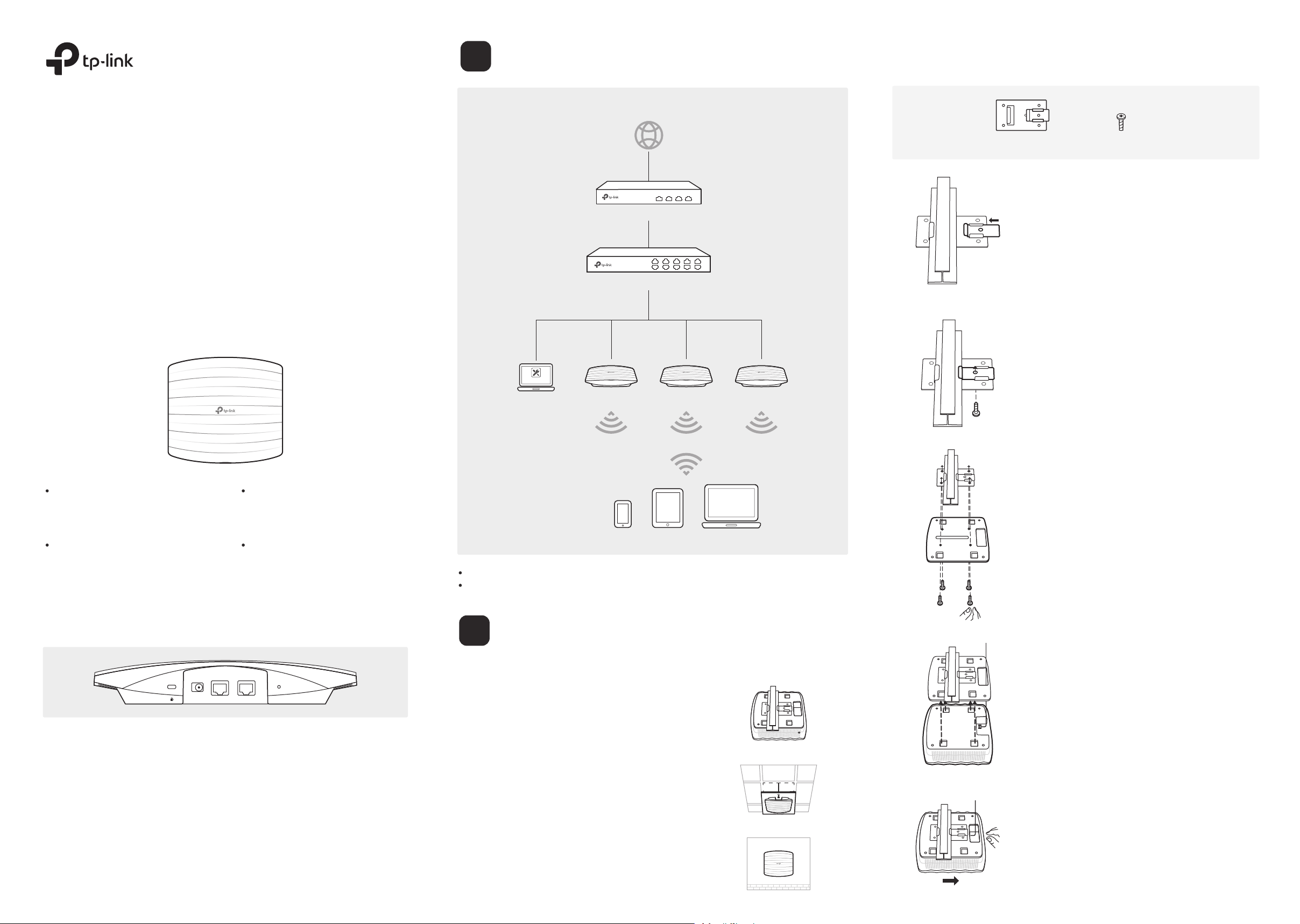
Typical Network Topology
Internet
Option 1: Ceiling Rail Mounting
Quick Installation Guide
AC1900 Wireless Dual Band Gigabit Ceiling Mount
Access Point
EAP330
LED Indication
EAP Controller
PC
Router
Switch
Ceiling T-rail Clip
M3×6 Pan-head Screws
(Qty.5)
1
Position the Ceiling T-rail Clip and push the movable
part toward the rail base.
2
Use an M3×6 pan-head screw to secure the T-rail
Clip onto the ceiling rail.
EAPEAP EAP
Solid Green
The device is working properly.
Flashing Red
System errors. RAM, Flash, Ethernet,
WLAN or firmware may be
malfunctioning.
Flashing Yellow
Firmware update is in progress. Do not
disconnect or power o the device.
Double-flashes Red, Green, Then Yellow
The device is being reset to its
factory default settings.
Interface Panel
ETH1(PoE) ETH2POWER
RESET
With the device powered on, press and hold the button for about 8 seconds until the
LED flashes red, then release the button. The device will restore to factory default
settings.
ETH1(PoE)
The port is used to connect to a router or a switch to transmit data or to a PSE (Power
Sourcing Equipment), such as a PoE switch, for both data transmission and Power
over Ethernet (PoE) through Ethernet cabling.
ETH2
The port is used to connect to a router or a switch to transmit data. ETH2 and ETH1
can be combined together to double the network backhaul capacity.
RESET
Clients
A DHCP server (typically a router) is required to assign IP addresses to the EAPs and clients in your local network.
The management host can be in the same or different network segment with the EAPs.
2
The EAP can be ceiling rail mounted, ceiling-mounted, or wall-mounted.
Hardware Installation
Option 1: Ceiling Rail Mounting
Option 2: Ceiling Mounting
Option 3: Wall Mounting
3
Attach the mounting bracket to the Ceiling T-rail Clip
using four M3x6 pan-head screws.
4
Make the Ethernet Cable pass through the xing
hole of the mounting bracket. Connect the cable to
the ETHERNET port and attach the EAP to the
bracket.
5
Push the EAP along the direction of arrows until it
locks into place, as shown on the left. Then adjust
the cable to make the exposed part hidden behind
the EAP.
Page 2
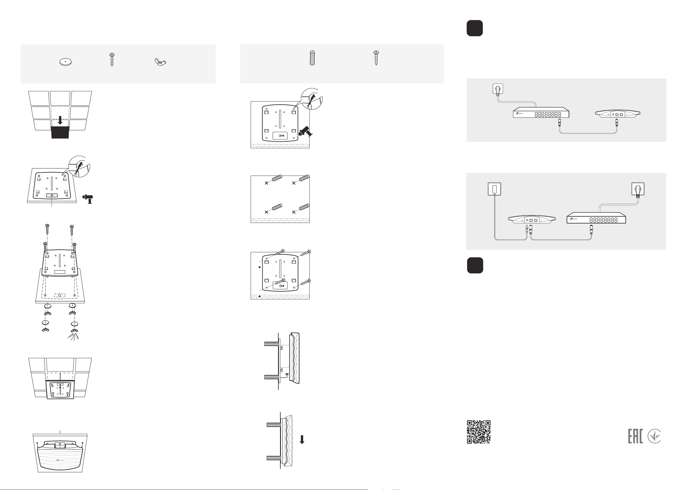
Option 2: Ceiling Mounting
Option 3: Wall Mounting
3
Power Supply
Washers
(Qty.4)
Hole for Ethernet cable
M3×30 Pan-head Screws
(Qty.4)
1
Remove the ceiling tile.
X4
2
Place the mounting bracket in the center of the
ceiling tile. Mark the four positions of the screw
holes and a hole for the Ethernet cable to feed
through.
Drill four 4mm holes for the screws and a 10mm
hole for the Ethernet cable.
Wing Nuts
(Qty.4)
Note: Install the EAP with the Ethernet port downward.
M3×28 Plastic Wall Anchors
(Qty.4)
X4
M3×20 Self-tapping Screws
(Qty.4)
1
If your Ethernet cable feeds through the wall, you
can position the mounting bracket to make the
cable through the xing hole. Mark the four
positions of the screw holes and then drill four 6mm
holes.
2
Insert the plastic wall anchors into the 6mm holes.
The EAP can be powered via a PSE device (such as a PoE switch) or a power adapter.
Via PoE Switch
Connect an Ethernet cable from the PoE switch to the ETHERNET port.
PoE Switch
Via Power Adapter
Plug one end of the provided power adapter into the POWER port of the EAP and the
other end to a standard electrical wall outlet.
Power Adapter
3
Secure the mounting bracket to the ceiling tile
using four M3x30 pan-head screws, washers
and wing nuts.
4
Feed the Ethernet cable through the hole. Then
set the ceiling tile back into place.
3
Secure the mounting bracket to the wall by driving
the self-tapping screws into the anchors. Make sure
that the shoulders of the mounting bracket are on
the outside.
4
Connect the Ethernet cable to the ETHERNET port
on the EAP and attach the EAP to the mounting
bracket, as shown on the left.
Switch
4
Software Configuration
To quickly set up a wireless network connection with mass EAPs, please follow the steps
below.
Note: The IP address of the management host must be reachable for the EAPs in the network. In this example, the
management host is in the same LAN as the EAPs.
Step 1: Installing the EAP Controller
On the management host, download the EAP Controller installation file from the product
support page at www.tp-link.com. Run the file and follow the wizard to install the EAP
Controller.
Step 2: Configuring the EAP Controller
Launch the EAP Controller and follow the configuration wizard to create a primary
wireless network. After the wizard is finished, a login screen will appear. Enter the admin
name and password you created and click Sign In.
Step 3: Adopting the EAP devices
5
Connect the Ethernet cable to the ETHERNET
port and push the EAP along the direction of
arrows until it locks into place, as shown on the
left. Then adjust the cable to make the exposed
part hidden behind the EAP.
5
Push the EAP along the direction of arrows until it
locks into place, and then adjust the cable to make
the exposed part hidden behind the EAP.
Adopt the EAP devices in the Controller management interface to change their status
from Pending to Connected.
For technical support, User Guide and other information, please
visit http://www.tp-link.com/support, or simply scan the QR code.
The products of TP-Link partly contain software code developed by third parties, including software code subject to the GNU
General Public License (“GPL”). As applicable, the terms of the GPL and any information on obtaining access to the respective GPL
Code used in TP-Link products are available to you in GPL-Code-Centre under (http://www.tp-link.com/en/support/gpl/). The
respective programs are distributed WITHOUT ANY WARRANTY and are subject to the copyrights of one or more authors. For
details, see the GPL Code and other terms of the GPL.
©2018 TP-Link 7106507941 REV2.0.2
 Loading...