

Page 1

User Guide
Omada Controller Software
1910012624 REV 3.4.0
July 2019
Page 2

CONTENTS
1 Quick Start ....................................................................................................................... 1
1.1 Determine the Network Topology .........................................................................................................................2
1.1.1 Management on the local Network ............................................................................................................... 2
1.1.2 Management via Cloud Access......................................................................................................................4
1.2 Install Omada Controller Software ........................................................................................................................5
1.2.1 Installation on Windows Host .......................................................................................................................... 5
1.2.2 Installation on Linux Host ................................................................................................................................. 5
1.3 Inform the EAPs of the Controller Host's Address ..........................................................................................7
1.4 Start and Log In to the Omada Controller ...........................................................................................................8
1.4.1 Launch Omada Controller ................................................................................................................................ 9
1.4.2 Do the Basic Configurations............................................................................................................................9
1.4.3 Log In to the Management Interface ......................................................................................................... 12
1.5 Create Sites and Adopt EAPs ............................................................................................................................... 13
1.5.1 Create Sites ........................................................................................................................................................ 13
1.5.2 Adopt the EAPs ................................................................................................................................................. 16
1.6 Monitor and Manage the EAPs ............................................................................................................................. 17
2 Monitor and Manage the Network .........................................................................18
2.1 View the Statistics of the Network .....................................................................................................................19
2.1.1 View the Client Distribution on SSID ......................................................................................................... 19
2.1.2 Have a Quick Look at EAPs and Clients ................................................................................................... 19
2.1.3 View Current Usage-Top EAPs ................................................................................................................... 20
2.1.4 View Recent Activities .................................................................................................................................... 20
2.2 Monitor the Network with the Map .....................................................................................................................21
2.2.1 Add a Map ............................................................................................................................................................ 21
2.2.2 Monitor the EAPs on the Map ...................................................................................................................... 24
2.3 Monitor and Manage the EAPs ............................................................................................................................. 25
2.3.1 Manage the EAPs in Different Status ........................................................................................................ 25
Page 3

2.3.2 View the Detailed Information of EAPs..................................................................................................... 26
2.3.3 Manage the EAPs in the Action Column .................................................................................................. 26
2.4 Monitor and Manage Clients ................................................................................................................................. 28
2.4.1 View the Current Information of Clients .................................................................................................. 28
2.4.2 Manage Clients in the Action Column ....................................................................................................... 28
2.5 View Clients Statistics During the Specified Period ................................................................................... 29
2.5.1 Select a Specified Period .............................................................................................................................. 29
2.5.2 View the History Information of Clients ................................................................................................... 30
2.5.3 Manage Clients in the Action Column ....................................................................................................... 30
2.6 Manage the Rogue APs List ..................................................................................................................................30
2.6.1 Manage the Untrusted Rogue APs List .................................................................................................... 31
2.6.2 Manage the Trusted Rogue APs List ......................................................................................................... 31
2.7 View Past Guest Authorization .............................................................................................................................32
2.8 View Logs ..................................................................................................................................................................... 32
3 Configure the EAPs Globally ................................................................................... 34
3.1 Wireless Network ...................................................................................................................................................... 35
3.1.1 Add Wireless Networks .................................................................................................................................. 35
3.1.2 Configure Advanced Wireless Parameters ............................................................................................ 45
3.1.3 Configure Band Steering ............................................................................................................................... 47
3.1.4 Configure Mesh ................................................................................................................................................. 48
3.2 Access Control ..........................................................................................................................................................53
3.3 Portal Authentication ...............................................................................................................................................54
3.3.1 No Authentication............................................................................................................................................. 55
3.3.2 Simple Password .............................................................................................................................................. 59
3.3.3 Local User ............................................................................................................................................................ 63
3.3.4 Voucher ................................................................................................................................................................ 71
3.3.5 SMS ........................................................................................................................................................................ 78
3.3.6 Facebook ............................................................................................................................................................. 83
3.3.7 External RADIUS Server ................................................................................................................................. 84
Page 4

3.3.8 External Portal Server ..................................................................................................................................... 90
3.4 Free Authentication Policy .................................................................................................................................... 91
3.5 MAC Filter ....................................................................................................................................................................92
3.6 Scheduler ..................................................................................................................................................................... 94
3.7 QoS ................................................................................................................................................................................. 96
3.8 Site Settings ...............................................................................................................................................................99
3.8.1 LED ......................................................................................................................................................................... 99
3.8.2 Device Account ...............................................................................................................................................100
3.8.3 Reboot Schedule ............................................................................................................................................100
3.8.4 Log Settings .....................................................................................................................................................101
3.8.5 Batch Upgrade .................................................................................................................................................102
3.8.6 SSH ......................................................................................................................................................................104
3.8.7 Management VLAN ........................................................................................................................................105
4 Omada Cloud Service ............................................................................................. 106
4.1 Configure the Cloud Access .............................................................................................................................. 107
4.1.1 Enable Cloud Access ....................................................................................................................................107
4.1.2 Manage the Cloud Users .............................................................................................................................107
4.2 Manage the Controller via Omada Cloud ...................................................................................................... 109
4.2.1 Access the controller via Omada Cloud ................................................................................................110
4.2.2 Change your TP-Link ID information .......................................................................................................112
5 Configure the EAPs Separately .......................................................................... 113
5.1 View the Information of the EAP ....................................................................................................................... 114
5.1.1 Active Channel Information ........................................................................................................................114
5.1.2 Overview ............................................................................................................................................................115
5.1.3 LAN .......................................................................................................................................................................115
5.1.4 Radio ....................................................................................................................................................................116
5.2 View Clients Connecting to the EAP ............................................................................................................... 116
5.2.1 User ......................................................................................................................................................................116
5.2.2 Guest ...................................................................................................................................................................117
Page 5

5.3 View Mesh Information of the EAP .................................................................................................................. 117
5.3.1 Uplinks ................................................................................................................................................................117
5.3.2 Downlinks ..........................................................................................................................................................118
5.4 Configure the EAP ................................................................................................................................................. 118
5.4.1 Basic Config ......................................................................................................................................................118
5.4.2 IP Setting ............................................................................................................................................................119
5.4.3 Radio ....................................................................................................................................................................120
5.4.4 Load Balance ....................................................................................................................................................121
5.4.5 WLANs ................................................................................................................................................................122
5.4.6 LED .......................................................................................................................................................................122
5.4.7 Trunk Settings (Only for EAP330) .............................................................................................................123
5.4.8 Rogue APs Detection ....................................................................................................................................123
5.4.9 Local LAN Port Settings (Only for EAP115-Wall and EAP225-Wall) ...........................................124
5.4.10 Forget this AP ................................................................................................................................................124
6 Manage the Omada Controller ............................................................................ 125
6.1 User Account ........................................................................................................................................................... 126
6.2 General Setting ....................................................................................................................................................... 127
6.2.1 Configure Controller Name .........................................................................................................................127
6.2.2 Configure Mail Server ...................................................................................................................................127
6.3 History Data Retention ......................................................................................................................................... 129
6.4 Backup&Restore..................................................................................................................................................... 130
6.5 Auto Backup ............................................................................................................................................................. 130
6.6 Migrate ....................................................................................................................................................................... 133
6.6.1 Controller Migrate ..........................................................................................................................................133
6.6.2 Site Migrate .......................................................................................................................................................137
6.7 Information About the Software ....................................................................................................................... 141
7 Application Example ............................................................................................... 142
7.1 Basic Configuration ............................................................................................................................................... 143
7.2 Advanced Settings ................................................................................................................................................ 143
Page 6

7.2.1 Monitor the EAPs with Map .........................................................................................................................143
7.2.2 Configure Portal Authentication ...............................................................................................................144
7.2.3 Create a SSID for the Employees .............................................................................................................146
7.2.4 Configure Scheduler .....................................................................................................................................147
Appendix: Omada App .............................................................................................. 149
1 Install Omada App on the Mobile Device ...................................................................................................... 150
2 Manage your Network in Standalone Mode ................................................................................................. 150
3 Manage your Network in Controller Mode .................................................................................................... 153
3.1 Locally manage your EAPs using the Omada App ...........................................................................153
3.2 Remotely manage your EAPs using the Omada App ......................................................................156
Page 7

1
Omada Controller is a management software for TP-Link EAPs. With this software, you can centrally
manage your EAPs, such as configure EAPs in batches and conduct real-time monitoring of EAPs
locally or remotely through Omada Cloud service.
Follow the steps below to complete the basic settings of Omada Controller.
1. Determine the Network Topology
2. Install Omada Controller Software
3. Inform the EAPs of the Controller Host's Address
4. Start and Log In to the Omada Controller
5. Create Sites and Adopt the EAPs
6. Monitor and Manage the EAPs
Quick Start
1
Page 8

1.1 Determine the Network Topology
There are two methods to centrally manage EAPs via Omada Controller:
Management on the Local Network
■
Management via Cloud Access
■
Determine your management method according to your need and refer to the following
introductions to build your network topology.
Tips:
Omada app offers a convenient way to access the Omada Controller and adopt EAPs. With Local Access and
Cloud Access function on the Omada app, you can manage the controller at local and remote sites. For more
detailed information about Omada app, refer to
1.1.1 Management on the local Network
There are two kinds of network topologies to centrally manage EAPs on the local network:
Omada Controller and EAPs are in the same subnet.
■
Appendix: Omada App
.
Omada Controller and EAPs are in different subnets.
■
Determine your management method according to your need and refer to the following
introductions to build your network topology.
Management in the Same Subnet
If your Omada Controller and EAPs are in the same subnet, refer to the following network topology.
A router acts as a DHCP server to assign IP addresses to EAPs and clients. Omada Controller
should be installed on one host, which is called as Controller Host. The other hosts in the same
LAN can access the Controller Host to manage the network. Taking the following topology as an
example, you can enter “https://192.168.0.100:8043“ in a web browser on Host B to visit the Omada
Controller interface on Host A. It's recommended to set a static IP address to the Controller Host
for the convenient login to the Omada Controller interface.
2
Page 9
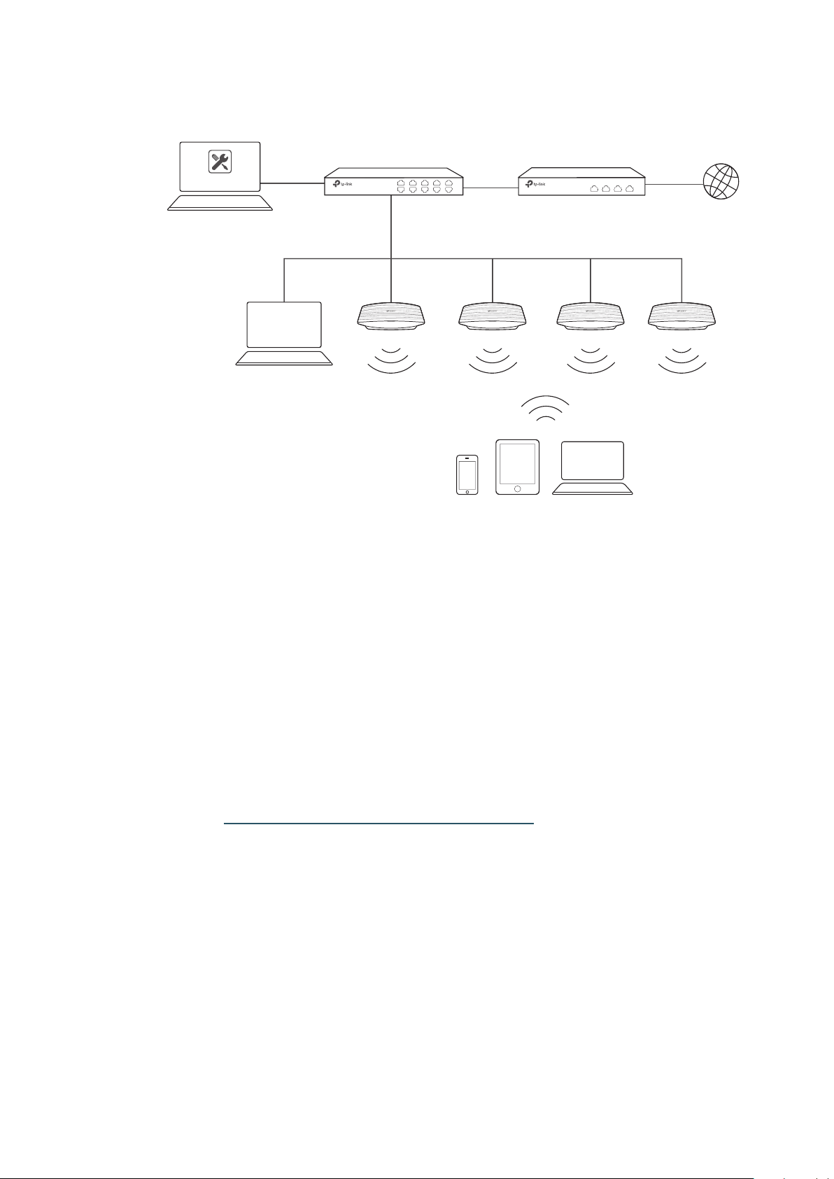
Host A (Controller Host)
IP: 192.168.0.100/24
EAPs
Layer 2 Switch
Omada Controller
Router (DHCP Server)
LAN IP:192.168.0.1/24
Internet
Host B
IP: 192.168.0.200/24
Clients
Note:
• Omada Controller must be running all the time when you manage the network.
• Omada Controller can be running on only one host in a LAN. When other users in the LAN try to launch
Omada Controller on their own hosts, they will be redirected to the host that is already running Omada
Controller.
Management in Different Subnets
If your Omada Controller and EAPs are in different subnets, refer to the following topology.
A router acts as the gateway of the network. A layer 3 switch acts as a DHCP server to assign IP
addresses to EAPs and clients. The Controller Host and the EAPs are connected to the switch's
different network segments. To help EAPs find the Controller Host, Omada Discover Utility should
be installed on Host B which is in the same subnet with the EAPs. For how to use Omada Discovery
Utility, refer to Inform the EAPs of the Controller Host’s Address.
3
Page 10
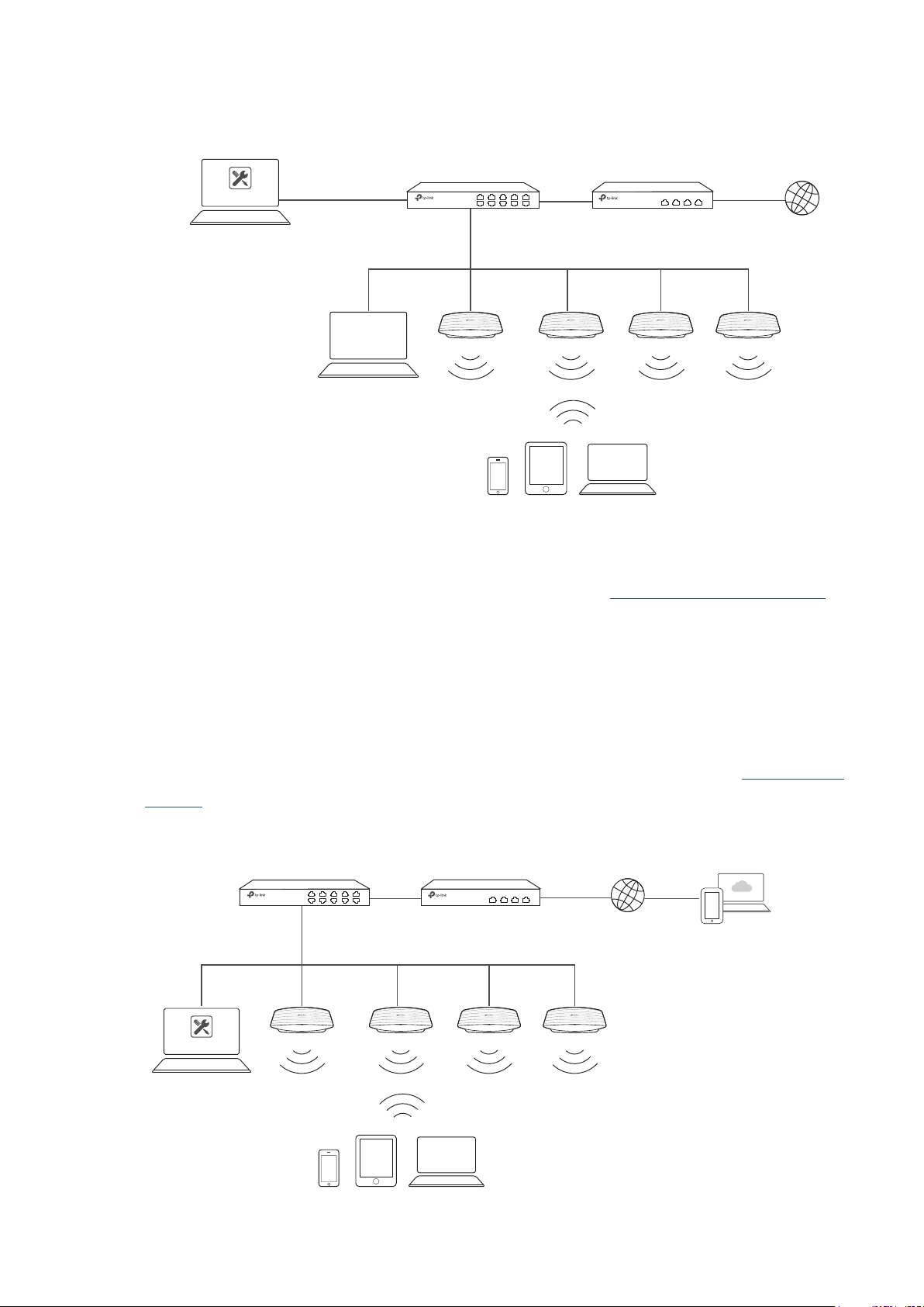
Host A (Controller Host)
IP: 192.168.1.100/24
Omada Controller
192.168.1.0/24
192.168.2.0/24
Layer 3 Switch
(DHCP Server)
LAN
Router
Internet
WAN
Omada
Discovery Utility
Host B
IP: 192.168.2.100/24
1.1.2 Management via Cloud Access
With Cloud Access enabled on the Omada Controller, you can use https://omada.tplinkcloud.com to
remotely access and monitor multiple controllers. If you want to manage EAPs remotely via Omada
Cloud , refer to the following topology.
A router acts as the gateway of the network. A Layer 3 switch acts as a DHCP server to assign
IP addresses to EAPs and clients. The management device is not on the local network. On the
management device, you can launch a web browser to remotely launch Omada Controller to
manage EAPs via Omada Cloud. For more details about Cloud Access, refer to Omada Cloud
EAPs
Clients
Service .
Omada Controller
Controller Host
Switch
LAN
Router
Internet
WAN
Management Devices
EAPs
Clients
4
Page 11

1.2 Install Omada Controller Software
We provide Omada Controller for both Windows and Linux operating systems. Determine your
operation system and follow the introductions below to install Omada Controller.
1.2.1 Installation on Windows Host
Make sure your PC meets the following requirements of hardware and system, then properly install
the Omada Controller software.
Hardware Requirements
Omada Controller can manage up to 1500 EAPs if the Controller Host has enough hardware
resources. To guarantee operational stability for managing 1500 EAPs, we recommend that you use
the hardware which meets or exceeds the following specifications:
CPU: Intel Core i3-8100, i5-6500, or i7-4700 with 2 or more cores and 4 or more threads.
Memory: 6 GB RAM or more.
System Requirements
Operating System: Microsoft Windows 7/8/10/Server.
Web Browser: Mozilla Firefox 32 (or above), Google Chrome 37 (or above), Opera 24 (or above), or
Microsoft Internet Explorer 11 (or above).
Note:
We recommend that you deploy Omada Controller on a 64-bit operating system to guarantee the software
stability.
Install Omada Controller
Download the installation file of Omada Controller from the website
en/download/EAP-Controller.html
Controller software. After successful installation, a shortcut icon
created on your desktop.
1.2.2 Installation on Linux Host
https://www.tp-link.com/
. Then follow the instructions to properly install the Omada
of the Omada Controller will be
Two versions of installation package are provided: .tar.gz file and .deb file. The .tar.gz file can be
used in multiple versions of Linux operating system. And the .deb file can be used in Ubuntu and
Debian.
Make sure your PC meets the following requirements of hardware and system, then choose the
proper installation files to install the Omada Controller software.
5
Page 12

Hardware Requirements
Omada Controller can manage up to 1500 EAPs if the Controller Host has enough hardware
resources. To guarantee operational stability for managing 1500 EAPs, we recommend that you use
the hardware which meets or exceeds the following specifications:
CPU: Intel Core i3-8100, i5-6500, or i7-4700 with 2 or more cores and 4 or more threads.
Memory: 6 GB RAM or more.
System Requirements
Operating System: 64-bit Linux operating system, including Ubuntu 14.04/16.04/17.04, CentOS
6.x/7.x, Fedora 20 (or above) and Debian 9.8.
Web Browser: Mozilla Firefox 32 (or above), Google Chrome 37 (or above), Opera 24 (or above), or
Microsoft Internet Explorer 11 (or above).
Install the Omada Controller
Download the installation file of Omada Controller from our website
download/EAP-Controller.html.
Make sure you have jsvc and curl installed in your system before installation, which is vital to the
smooth running of the system. If your system does not have jsvc or curl installed, you can install it
manually with the command: apt-get install or yum install. For example, you can use the command:
apt-get install jsvc or yum install jsvc to get jsvc installed. And if dependencies are missing, you
can use the command: apt-get -f install to fix the problem.
■
Install the
Follow the steps below to install Omada Controller on your Linux PC:
1. Make sure your PC is running in root mode. You can use this command to enter root mode:
sudo
2. Extract the tar.gz file using the command:
tar zxvf Omada_Controller_v3.0.5_linux_x64_targz.tar.gz
.tar.gz file
https://www.tp-link.com/en/
3. Install Omada Controller using the command:
sudo./install.sh
■
Install the
Follow the steps below to install Omada Controller on your Linux PC:
1. Make sure your PC is running in root mode. You can use this command to enter root mode:
.deb file
6
Page 13

sudo
2. Install the .deb file using the command:
dpkg -i Omada_Controller_v3.0.5_linux_x64.deb
Tips:
• For installing the .tar.gz, if you want Omada Controller to run as a user (it runs as root by default) you should
modify OMADA_USER value in bin/control.sh.
• To uninstall Omada Controller, go to the installation path: /opt/tplink/EAPController, and run the command:
sudo ./uninstall.sh.
• During uninstallation, you can choose whether to backup the database. The backup folder is /opt/tplink/
eap_db_backup.
• During installation, you will be asked whether to restore the database if there is any backup database in the
folder /opt/tplink/eap_db_backup.
1.3 Inform the EAPs of the Controller Host's Address
If your Controller Host and EAPs are in the same network segment, you can skip this section.
If your Controller Host and EAPs are in different subnets, you need to install Omada Discovery
Utility on a host that is in the same network segment with the EAPs. Omada Discovery Utility can
help EAPs find the Controller Host.
System Requirements
Windows 7/8/10/Server
Mac OS X 10.7/10.8/10.9/10.10/10.11
Install and Use Omada Discovery Utility
Follow the steps below to install Omada Discovery Utility and use it to inform the EAPs of the
Controller Host's IP address:
1. Download the installation file with the latest version from the website https://www.tp-link.com/
en/download/EAP-Controller.html#EAP_Discovery_Tool.
2. Make sure you have JRE (Java Runtime Environment) with version1.8 installed on your system
before installation. If your system loses JRE, download JRE from the website https://www.oracle.
com/technetwork/java/javase/downloads/jre8-downloads-2133155.html and install it on your
system.
3. For Windows OS, run the start-omada-discovery-utility.bat to open the Omada Discovery
Utility. For Mac OS, use the command java –jar ** to open the Omada Discovery Utility. Then the
following window will pop up. This window shows the information of all EAPs in the same LAN.
7
Page 14
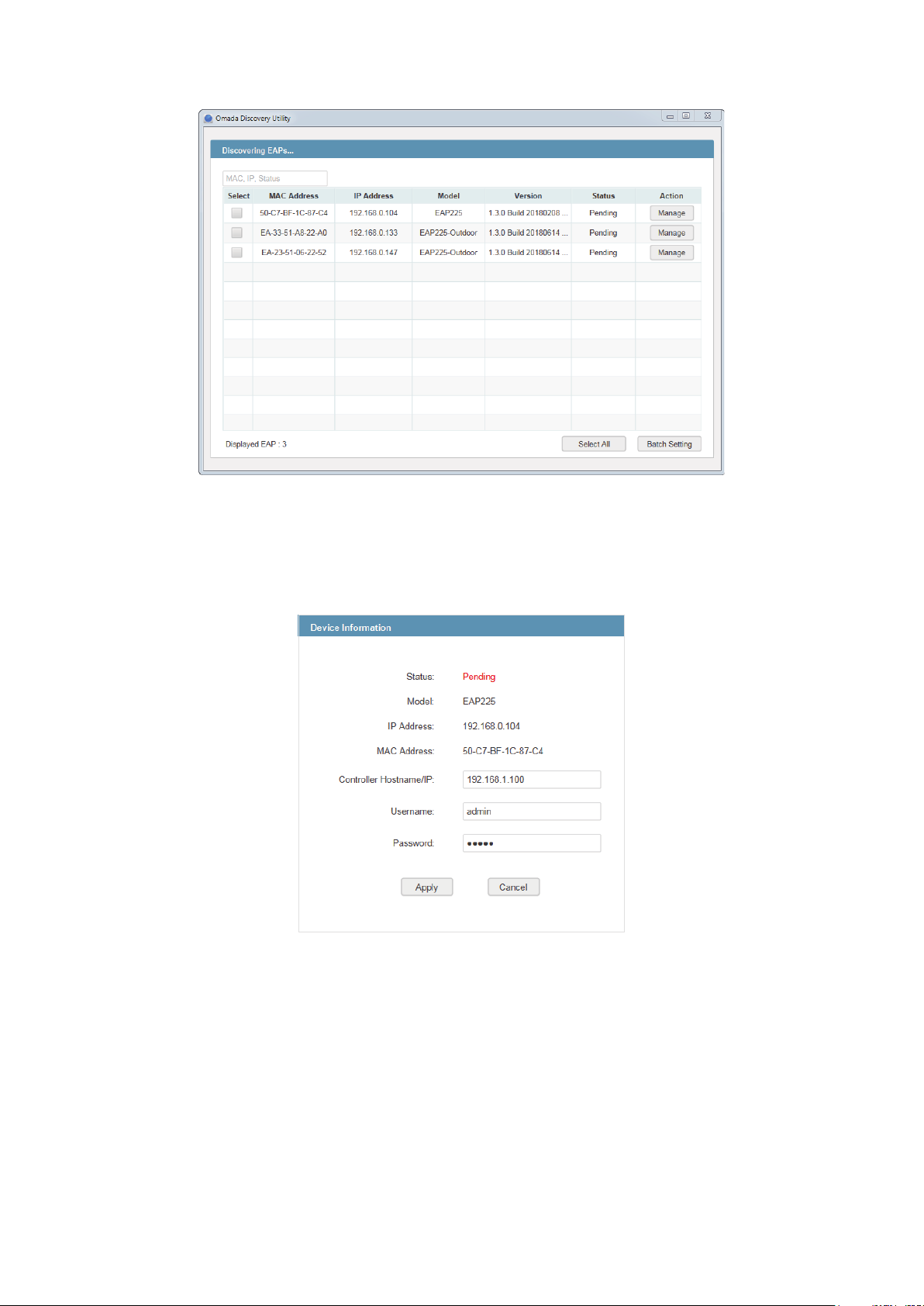
4. Click Manage in the Action column or select multiple EAPs and click Batch Setting.
5. Enter the hostname or IP address of the Controller Host.
6. Enter the EAP’s username and password (both are admin by default).
7. Click Apply to inform the EAP of the Controller Host's hostname or IP address. And then the
connection can be established between the EAP and the Controller Host.
1.4 Start and Log In to the Omada Controller
Launch Omada Controller and follow the instructions to complete the basic configurations, and
then you can log in to the management interface.
8
Page 15
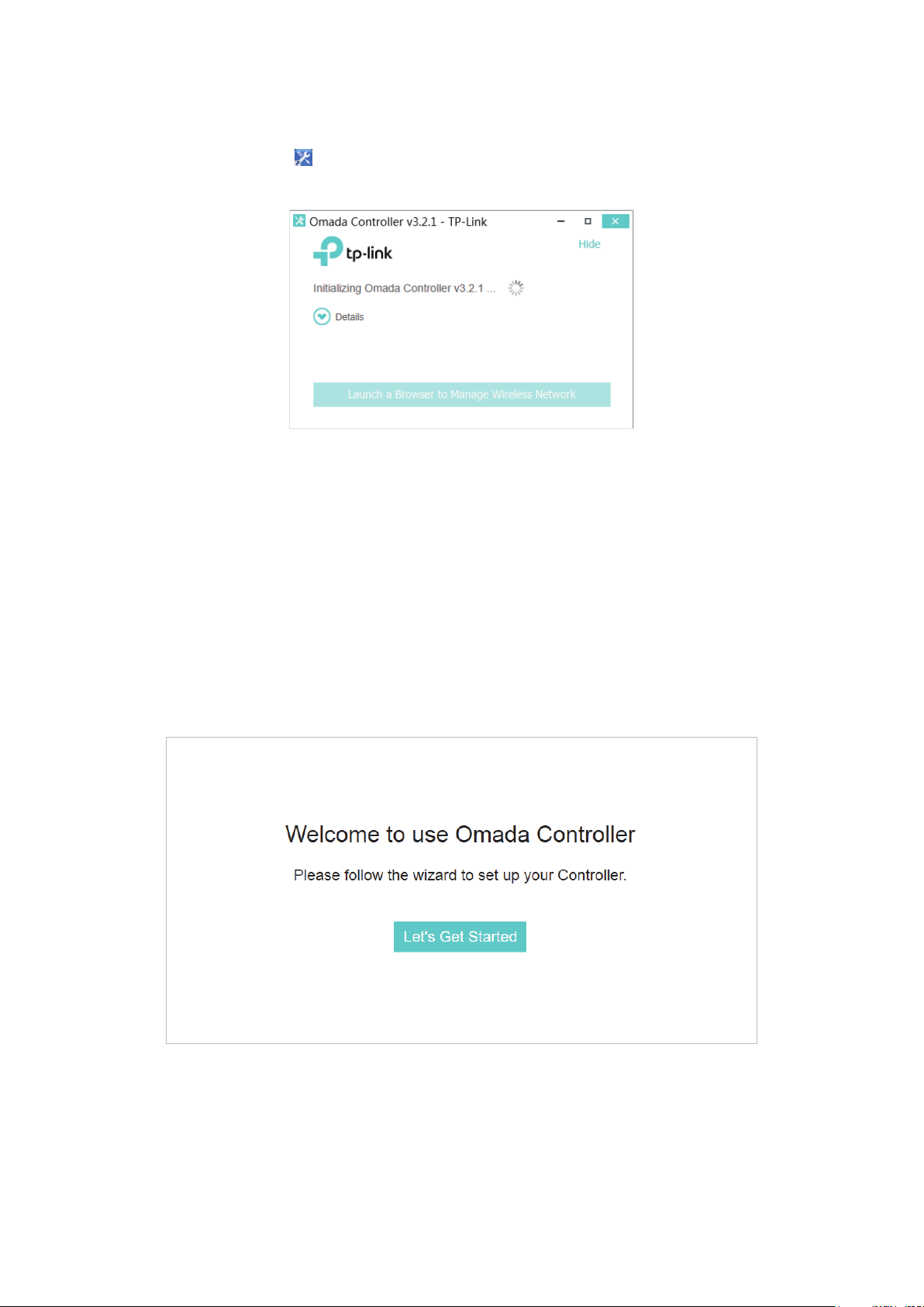
1.4.1 Launch Omada Controller
Double click the icon and the following window will pop up. You can click Hide to hide this window
but do not close it. After a while, your web browser will automatically open.
Note:
• If your browser does not open automatically, click Launch a Browser to Manage Wireless Network. You
can also launch a web browser and enter http://127.0.0.1:8088 in the address bar.
• If your web browser opens but prompts a problem with the website's security certificate, click Continue.
• Only one Omada Controller can run in a LAN. If an Omada Controller has already been running on a host
that is in your LAN, you will be redirected to the Omada Controller interface on that host.
1.4.2 Do the Basic Configurations
In the web browser you can see the configuration page. Follow the setup wizard to complete the
basic settings for Omada Controller.
1. Click Let’s Get Started.
2. Specify a name for Omada Controller. Click Next.
9
Page 16
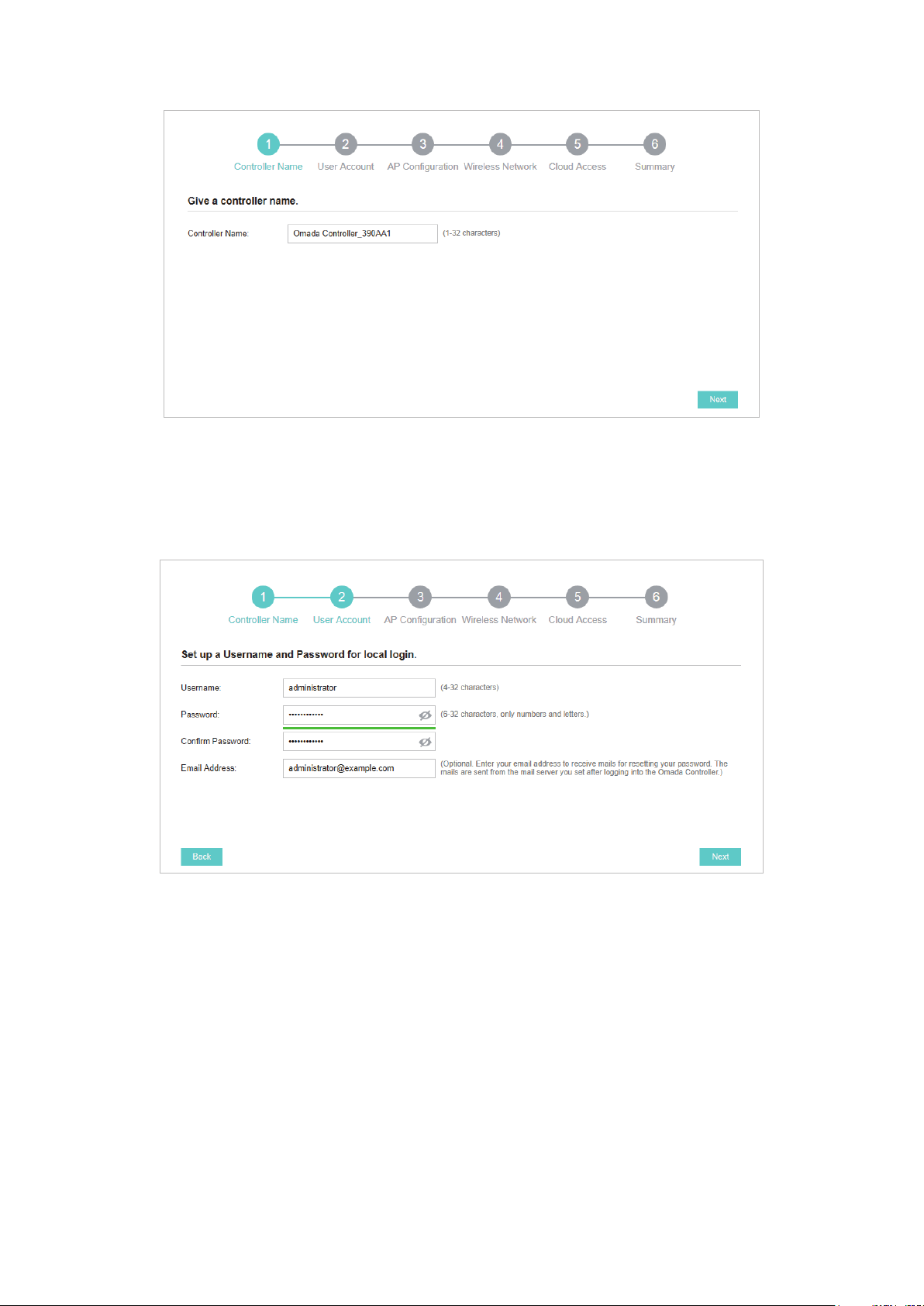
3. Specify a username and password for the login account. Specify the email address for resetting
your password in case that you forget the password. After logging in Omada Controller, set a
mail server so that you can receive emails and reset your password. For how to set a mail server,
refer to Configure Mail Server. Click Next.
4. The setup page displays all the detected EAPs in the network. Select one or more EAPs to be
managed and click Next.
10
Page 17
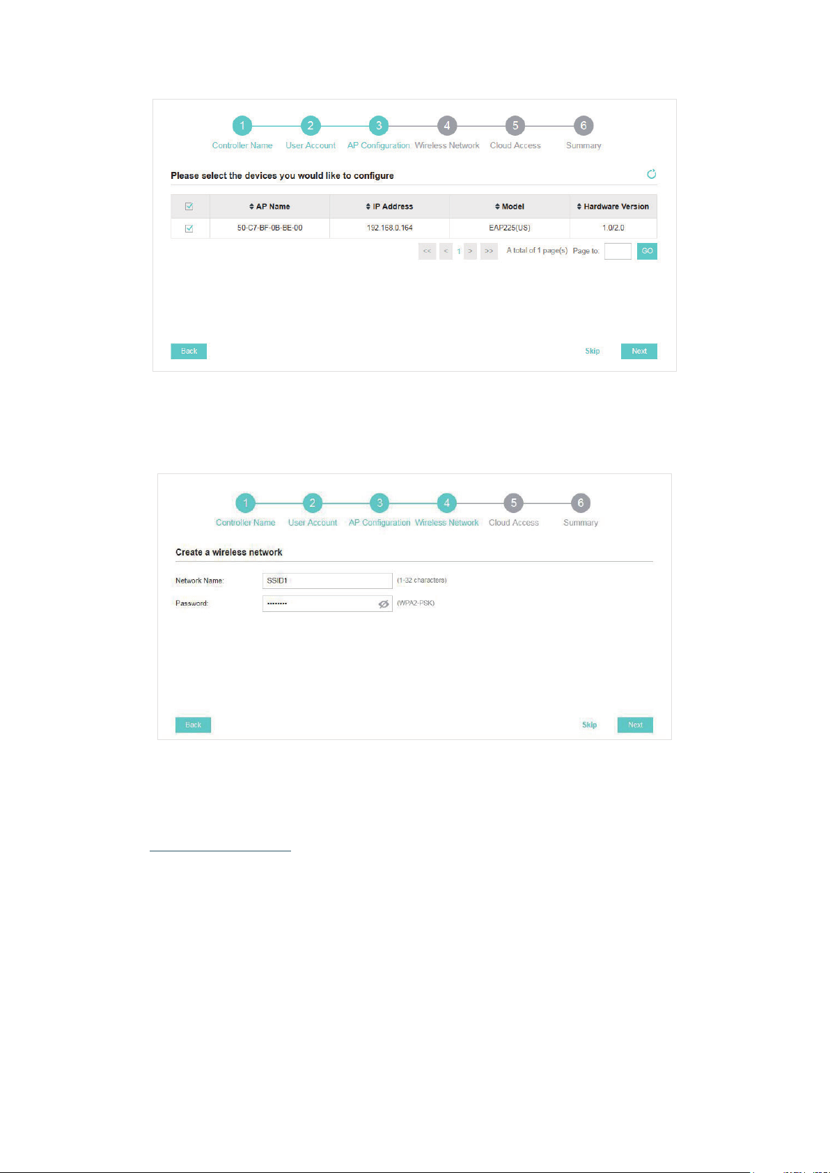
5. Set an SSID name (wireless network name) and password for the EAPs to be managed. Omada
Controller will create two wireless networks, a 2.4GHz one and a 5GHz one, both encrypted in
WPA2-PSK mode. Click Next.
6. If you want to manage EAPs via Omada Cloud, enable the Cloud Access button, and bind your
TP-Link ID to your Omada Controller, and then click Next. If you want to manage EAPs on the
local network, you can just click Skip. For more details about Omada Cloud, please refer to
Omada Cloud Service in chapter 4.
11
Page 18

7. Review your settings and click Finish.
1.4.3 Log In to the Management Interface
Once the basic configurations are finished, the browser will be redirected to the following page.
Log in to the management interface using the username and password you have set in the basic
configurations.
12
Page 19
Note:
In addition to the Controller Host, other hosts in the same LAN can also manage EAPs via remote access to the
Controller Host. For example, if the IP address of the Controller Host is 192.168.0.100 and Omada Controller is
running normally on this host, you can enter https://192.168.0.100:8043/login, or https://192.168.0.100:8043,
or http://192.168.0.100:8088 in the web browser of other hosts in the same LAN to log in to the Omada
Controller and manage EAPs. Or you can log in to Omada Controller on the management devices through
Omada Cloud service.
1.5 Create Sites and Adopt EAPs
Omada Controller can manage multiple EAP networks, which are called sites. Multiple sites are
logically separated, and each site has its own configurations. There is an initial site named Default.
The Default site cannot be deleted. If you have no need to manage EAPs with different sites, you
can edit the default site and skip the Create Sites section. However, Adopt the EAPs is a necessary
step to manage the EAPs.
1.5.1 Create Sites
There are three methods to create sites: Add Sites, Import Sites, and Copy Sites. Determine the
method according to your need and refer to the following introductions to create sites.
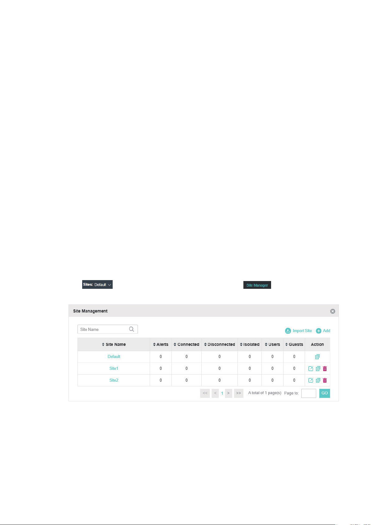
Add Sites
Follow the steps below to add a new site directly.
1. Click
window will pop up.
in the top left corner of the page and select , and then the following
13
Page 20
2. Click and enter a unique name for the new site.
3. Click Apply to create the site.
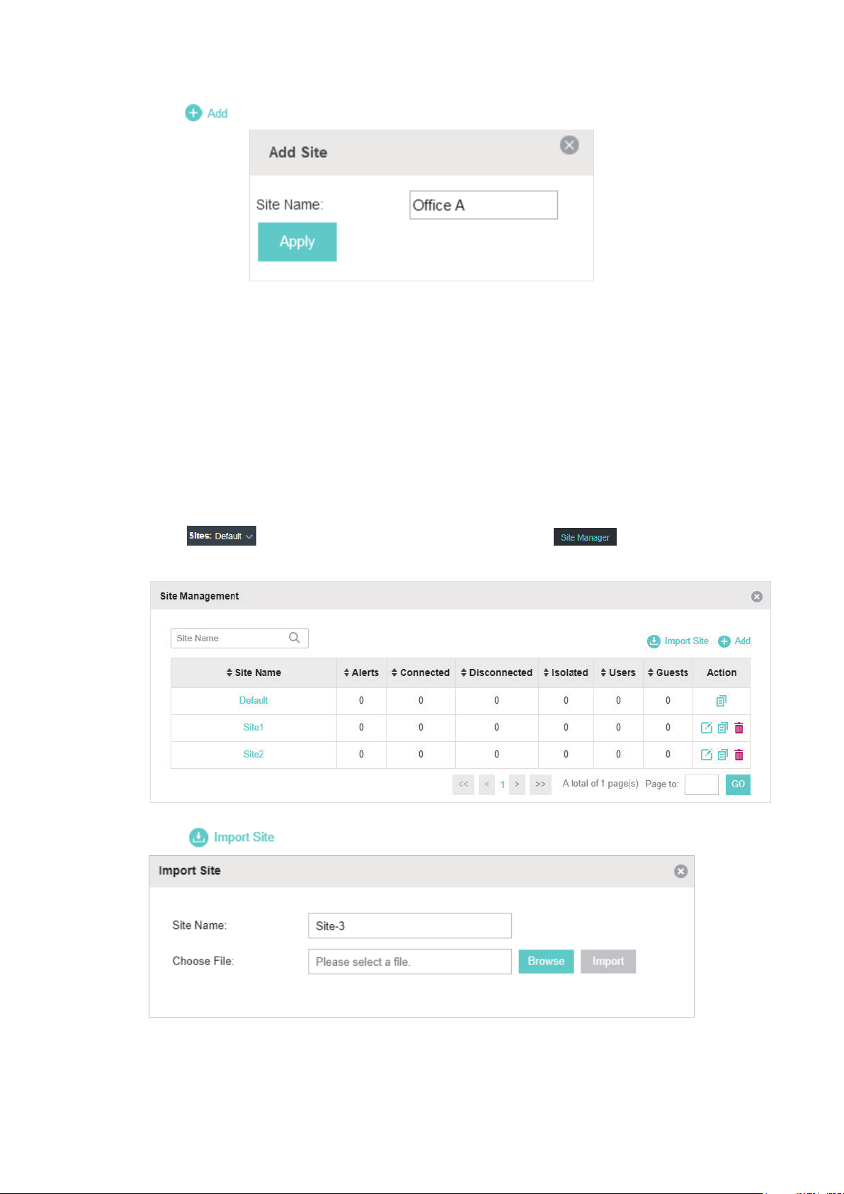
Import Sites
You can import the site from another controller. The site settings and EAPs in the site will be
imported to the new site.
Note:
• The site to be imported must come from a different controller.
• Importing sites is available only for local logged-in users.
1. Click in the top left corner of the page and select , and then the following
window will pop up.
2. Click and enter a unique name for the new site.
3. Click Browse to upload the backup file of other site and click Import to import the site.
14
Page 21
Tips:
To export sites (including site settings and EAPs in the sites) from one controller to another, use the Migrate
function. For more details about Migrate, refer to Migrate.
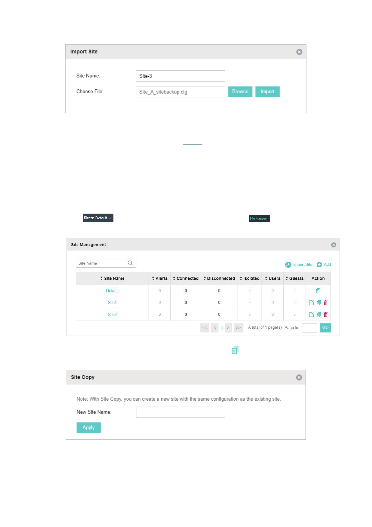
Copy Sites
With Site Copy, you can create a new site with the same settings as the existing sites on your
controller. Note that only the site settings will be copied. The EAPs will be still managed at the
original site.
1. Click
in the top left corner of the page and select , and then the following
window will pop up.
2. Select a site that you want copy all the settings and click in the Action column. Then enter a
unique name for the new site.
3. Click Apply to create the site.
15
Page 22
1.5.2 Adopt the EAPs
Omada Controller can discover all EAPs currently connected in the network and display their
connection status. All EAPs are in Pending status when first discovered by Omada Controller.
To manage the EAPs, you need to adopt them. In the quick setup process, Omada Controller will
automatically adopt the selected EAPs using the default username and password (both are admin).
However, if you have changed the username or password of your EAPs before, Omada Controller
cannot automatically adopt them, and you need to refer to the following steps to adopt them
manually.
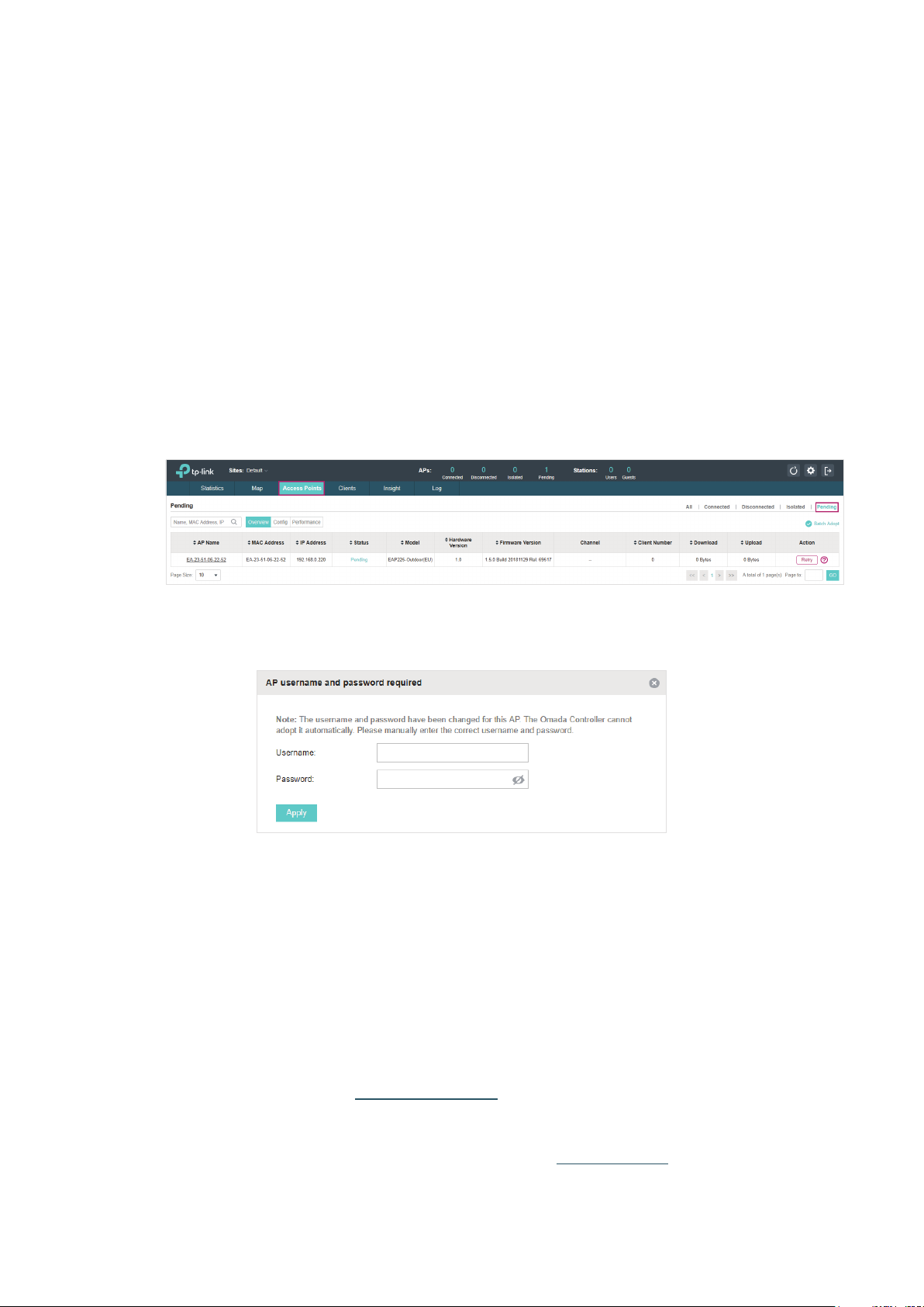
To ensure that all EAPs are adopted, follow the steps below:
1. Select a site and go to Access Points > Pending. The table displays all the EAPs that have not
been adopted.
2. Click the Retry button in the Action column and enter the current username and password of the
EAP. Click Apply.
Tips:
• If you have a new discovered EAP, you can click the Adopt button in the Action column to adopt the EAP.
Omada Controller will automatically adopt the EAP using the default username and password (both are
admin).
• If you have multiple new discovered EAPs, and all of them have the default username and password (both
are admin), you can click the Batch Adopt button to adopt them in batch. But if there are any EAPs with the
Retry button, it means that the username and password of these EAPs have been changed. You need to
first adopt them before batch adopt the rest EAPs.
3. After EAPs are adopted, the status will change from Pending to Connected. All the EAPs’
username and password will become the same as those of the Controller's administrator
account you created in the Basic Configuration.
Tips:
If you want to change the EAPs' username and password, refer to
16
Device Account
.
Page 23
1.6 Monitor and Manage the EAPs
When all the configurations above are finished, you can centrally monitor and manage the EAPs
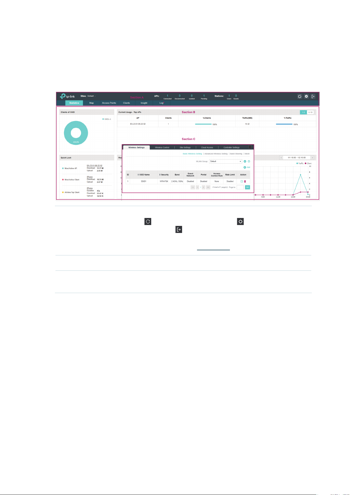
via the Omada Controller's management interface. The management interface is divided into three
sections as the following figure shows.
Section A In Section A, you can check the status of EAPs and clients in the network. Also,
you can click
wireless network, and click
to refresh the current page, click to globally configure the
to sign out from the management interface.
Furthermore, the Sites allows you to group your EAPs and manage them in
batches. To configure sites, refer to
Section B In Section B, you can centrally monitor the EAPs and clients.
Section C In Section C, you can globally configure the wireless network. The global
configurations will take effect on all the adopted EAPs.
Create Sites
.
17
Page 24

2
With Omada Controller you can monitor the EAPs and centrally manage your wireless network. This
chapter includes the following sections:
■ View the Statistics of the Network
■ Monitor the Network with the Map
■ Monitor and Manage the EAPs
■ Monitor and Manage Clients
■ View Clients Statistics during the Specified Period
■ Manage the Rogue APs List
■ View Past Guest Authorization
■ View Logs
Monitor and Manage the Network
18
Page 25

2.1 View the Statistics of the Network
Omada Controller collects all statistics of the managed EAPs and displays the statistical information
via graphs, pie charts and tables, providing an overview of your wireless network.
2.1.1 View the Client Distribution on SSID
A visual pie chart shows the client distribution on each SSID. For example, the SSID1 has one client,
which occupies 50% of all the clients.
2.1.2 Have a Quick Look at EAPs and Clients
This tab displays the Most Active AP, the Most Active Clients and the All-Time Top Client. You can
click the MAC address of the EAP or the client to see more details.
19
Page 26
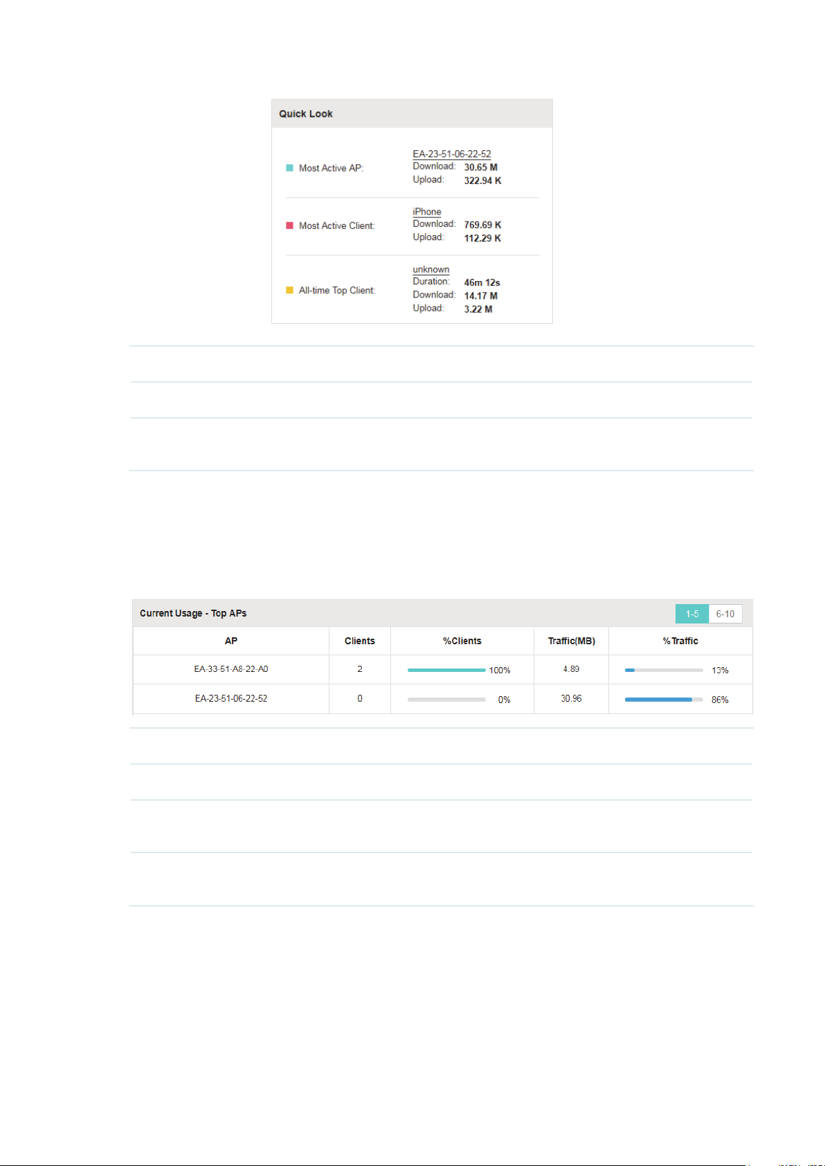
Most Active AP The current connected AP with the maximum traffic.
Most Active Client The current connected client with the maximum traffic.
All-time Top Client The client with the maximum traffic among all the clients that have ever
accessed the EAP network.
2.1.3 View Current Usage-Top EAPs
This tab lists the number of connected clients and the data traffic condition of the ten APs that use
the most traffic currently.
Clients The amount of clients connected to this EAP.
%Clients The proportion of current connected clients to the Top EAPs' total client amount.
Traffic (MB) The total amount of data transmitted by this EAP, which equals the sum of the
transmission traffic of all the current clients that connect to the AP.
%Traffic The proportion of the EAP's current data transmission amount to the Top EAPs' total
transmission amount.
2.1.4 View Recent Activities
The Recent Activities statistics can be toggled between a view for the past specific 24 hours and
one for the past specific 30 days.
The left ordinate axis indicates the traffic and the right one represents the number of the clients.
The abscissa axis shows the selected time period. Traffic indicates a visual graph of the network
20
Page 27
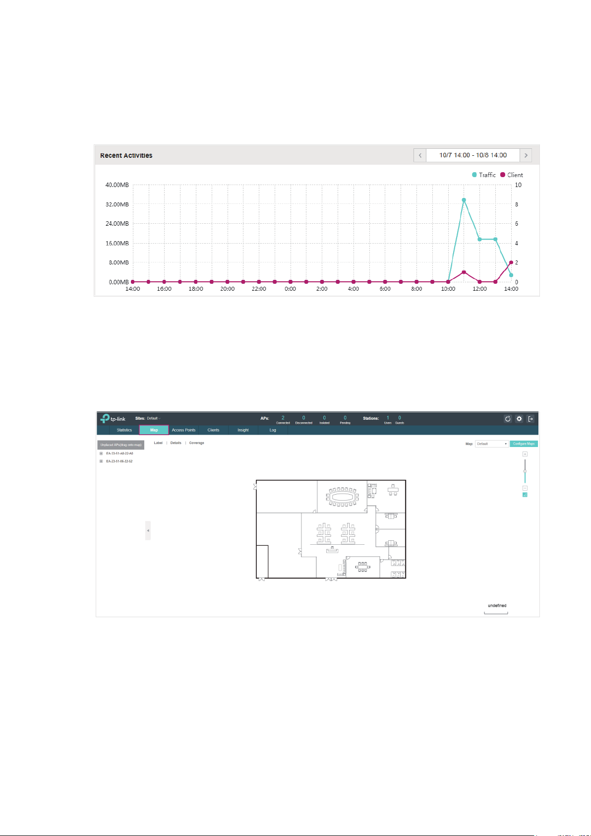
traffic during the selected time period. Client indicates a visual graph of the number of the
connected clients during the selected time period. For example, the statistics information at 15:00
indicates the traffic size and client number from 14:00 to 15:00. In the following figure, at 11 o’clock,
the traffic is about 34MB and there is 1 clients connected to the AP.
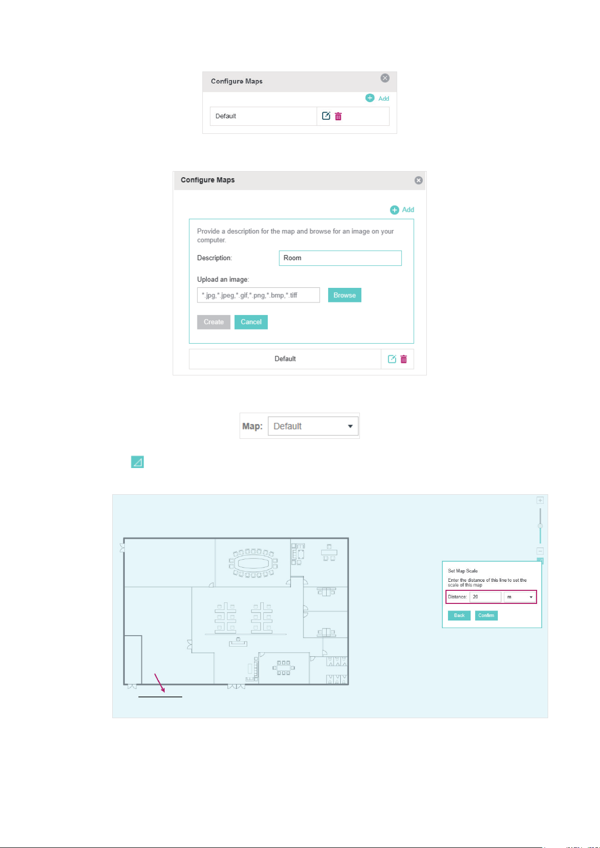
2.2 Monitor the Network with the Map
You can upload your local map images and monitor the status and coverage range of each EAP with
the map. When you initially launch Omada Controller, a default map is displayed as the following
figure shows. Follow the instructions below to add your own map and manage the EAPs via the map.
2.2.1 Add a Map
Prepare a map image in .jpg, .jpeg, .gif, .png, .bmp, .tiff format. And then follow the steps below to
add the map to the Omada Controller.
1. Click Configure Maps on the upper right corner of the Map page and click Add.
21
Page 28
2. Enter the map description, select your map image, and click Create.
3. Select your local map from the drop-down list on the upper right corner of the map area.
4. Click . Draw a line on the map and enter the distance the line represents. Then the Omada
Controller will compute and generate the map scale automatically based on your configuration.
5. Drag the EAPs from the Unplaced APs list to the appropriate locations on the map according to
their actual locations.
22
Page 29
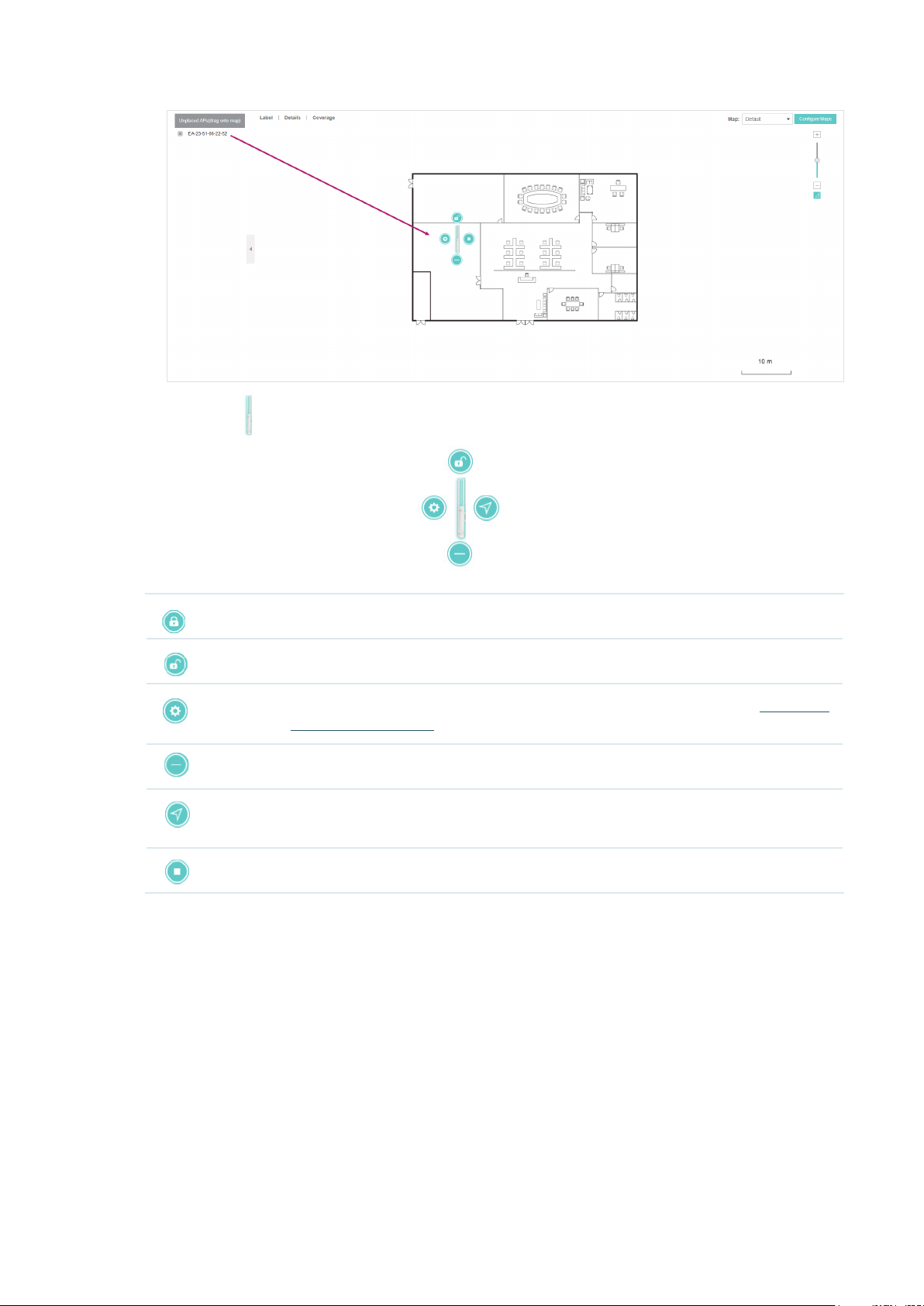
You can click to reveal additional options:
Lock the selected EAP in the current location on the map.
Unlock the selected EAP and you can drag it to another location.
Display the EAP's details and configure the wireless parameters. Refer to
the EAPs Separately
Remove the selected EAP back into the Unplaced APs list.
Flash the LED of the EAP on the map. Then the LED will flash for 10 minutes or until
the cancel button is clicked again.
Click the button to stop the LED from flashing.
.
Configure
23
Page 30

2.2.2 Monitor the EAPs on the Map
Click any of the following options to display EAP Label, Details, and Coverage on the map.
Label Display the EAP’s name. The default name is the MAC address of the EAP.
Details Display the EAP’s name, MAC address, IP address, transmitting/receiving channel,
number of connected users, and number of connected guests.
Coverage Display a visual representation of the wireless range covered by EAPs. The actual
signal coverage may be smaller than the visual coverage on the map because the
obstacles around the EAPs will weaken the signal.
24
Page 31

2.3 Monitor and Manage the EAPs
Omada Controller can discover all the EAPs currently connected to the network and display the
information of them on the Access Points page.
2.3.1 Manage the EAPs in Different Status
According to their connection status, EAPs are divided into four categories: Connected,
Disconnected, Isolated and Pending. You can view the EAPs in different status on different pages:
All Displays the information of all EAPs in different status.
Connected
Disconnected
Isolated
Displays the connected EAPs.
The status of connected EAPs includes two cases: Connected and Connected
(Wireless).
Connected: After you adopt a wired EAP in Pending status, its status will become
Provisioning, then Configuring and Connected eventually.
Connected (Wireless): In a mesh network, if an EAP has a successful wireless uplink,
its status will become Adopting (Wireless) and then Connected (Wireless).
Only connected EAPs can be managed. A connected EAP will turn into a pending one
after you forget it. You can refer to
on the page to forget all the connected EAPs.
Displays the disconnected EAPs.
If a connected EAP powers off or disconnects from the Omada Controller, it will be in
Disconnected status. When a disconnected EAP is reset to factory defaults or forgot,
it will turn into a pending one again. You can refer to
click Forget All on the page to forget all the disconnected EAPs.
Displays the isolated EAPs.
In a mesh network, when the EAP which has been managed before by Omada
Controller connects to the network wirelessly and cannot reach the gateway, it goes
into the Isolated state. The isolated EAP searches for wireless uplink and the LED on
the device turns green and flashes off every 5 seconds. To know more about mesh
network, refer to
Configure Mesh
Forget this AP
.
to forget an EAP or click Forget All
Forget this AP
to forget a EAP or
25
Page 32

Pending Displays the pending EAPs.
The status of pending EAPs includes three cases: Pending, Pending (Wireless) and
Managed by others.
Pending: All the EAPs with wired network connection are in pending status by default
when first discovered by Omada Controller.
Pending (Wireless): The factory default EAP with mesh functions and no wired network
connection is in Pending (Wireless) status when first discovered by Omada Controller.
Managed by others: An EAP is located on the same network as the controller, but
has been already managed by an existing controller before. You can provide the
username/password to unbind the EAP from the existing controller and begin adoption
in current controller.
Only after pending EAPs are adopted and connected, can you manage them. To adopt
pending EAPs, refer to
Adopt the EAPs
2.3.2 View the Detailed Information of EAPs
You can click Overview, Config, Performance or Mesh Network tab to view different detailed
information of EAPs.
.
Overview Displays the EAP's name, MAC address, IP address, status, model, hardware version,
firmware version, channel number of connected clients and download/upload bytes.
Config Displays the EAP’s name, MAC address, IP address, status, model, hardware version,
firmware version, WLAN Group bounded with the 2G and 5G of the EAP, and radio of
the 2G and 5G.
Performance Displays the EAP’s name, MAC address, IP address, status, model, hardware version,
firmware version, number of connected 2G clients and 5G clients, TX(Downloaded
Traffic), RX(Uploaded Traffic), TX 2G and TX 5G.
Mesh Network Displays the EAP’s name, MAC address, IP address, status, model, hardware version,
firmware version, number of connected clients, hops, uplink APs and downlink APs.
2.3.3 Manage the EAPs in the Action Column
You can execute the corresponding operation to the EAP by clicking an icon in the Action column.
Locate the EAP in the map.
Reboot the EAP.
26
Page 33
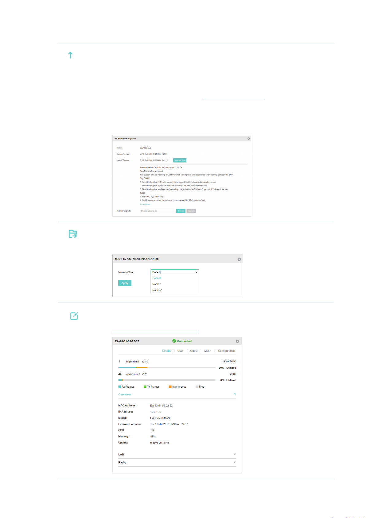
Upgrade the EAP.
Two options are available for upgrading: upgrade online and upgrade manually.
Upgrade online: With Cloud Access enabled on the controller and a TP-Link ID bound
with the controller, the latest firmware for the EAP can be detected by the controller
automatically. And you can upgrade the EAP online by clicking Upgrade Now. For more
details about Cloud Access, refer to
Upgrade manually: Click Browse to locate and choose the upgrade file in your
computer, then click Upgrade to install the latest EAP firmware. The Status will appear
as Upgrading until the process is complete and the EAP reconnects to the Omada
Controller.
Move the EAP to a site.
Omada Cloud Service
.
Select a site that has been created and click Apply. You can group all the EAPs by this
way and centrally manage them on each site.
Configure the EAP.
For detailed instructions about how to configure the EAP on this window, refer to
Configure the EAPs Separately
.
27
Page 34

Note:
• Only managed EAPs can be rebooted or upgraded.
• The EAP which is managed by the controller can not be logged in to its own management interface. To log
in to the EAP’s own management interface, forget the EAP in the controller first.
2.4 Monitor and Manage Clients
The Clients tab displays the clients connected to the EAP network.
2.4.1 View the Current Information of Clients
The clients are divided into two types: User and Guest. Users are the clients connected to the EAP
wireless network without the Portal Authentication. Guests are the clients connected to the EAP
wireless network with the Portal Authentication.
You can click the following tabs to respectively view the detailed information of users and guests.
All Clients The page displays the information of all clients including users and guests.
Users The page displays the information of Users.
Guests The page displays the information of Guests.
2.4.2 Manage Clients in the Action Column
You can execute the corresponding operation to the EAP by clicking an icon in the Action column:
Reconnect the client to the network.
Restrict the client's access to the network.
28
Page 35

Configure the rate limit of the client and view the connection history.
Enter the download limit and upload limit and click Apply.
If the client is a Guest, you can click this icon to cancel the authorization for it.
2.5 View Clients Statistics During the Specified Period
The Clients Statistics page under the Insight tab displays the information of clients that have
connected to the EAPs network during a specified period.
2.5.1 Select a Specified Period
Select a period from the drop-down menu. Then the page will display clients that have connected to
the EAPs network during the period.
29
Page 36

2.5.2 View the History Information of Clients
You can click the client's MAC address to get its connection history and configure the Rate Limit
feature for this client. In addition, you can click the following tabs to view the information of different
types of clients:
All The page displays the history information of all the clients.
User
Guest
Blocked The page displays the clients that have been blocked.
Rate Limited The page displays the clients that have been limited upload or download rate.
All The page displays the history information of all clients.
Offline Only The page displays the history information of the off-line clients.
The page displays the history information of Users.
Users are the clients connected to the EAP wireless network without the
Authentication
The page displays the history information of Guests.
Guests are the clients connected to the EAP wireless network with the
Authentication
.
.
2.5.3 Manage Clients in the Action Column
Portal
Portal
You can execute the corresponding operation to the EAP in the Action column:
Block the client's access to the network.
Resume the client's access.
Configure the rate limit of the client and view the connection history.
Remove the limit to the client’s upload or download rates.
2.6 Manage the Rogue APs List
A Rogue AP is an access point that has been installed on a secure network without explicit
authorization from a system administrator. The Omada Controller can scan all channels to detect
30
Page 37

all nearby EAPs. If rogue APs are detected, they will be shown on the Untrusted Rogue APs list.
Besides, you can move the untrusted rogue APs to the Trusted Rogue APs list.
By default, the Rogue AP Detection feature is disabled. To allow your EAP to detect nearby APs, you
need to enable this feature for this EAP. You can refer to Rogue AP Detection.
2.6.1 Manage the Untrusted Rogue APs List
The Untrusted Rogue APs page displays the detailed information of untrusted rogue APs.
You can execute the corresponding operation to the EAP in the Action column:
Move the untrusted rogue AP to the Trusted Rogue APs list.
Delete this record.
Delete all records.
2.6.2 Manage the Trusted Rogue APs List
The Trusted Rogue APs page displays the detailed information of trusted rogue APs.
You can execute the corresponding operation to the EAP by clicking an icon in the Action column:
Move the trusted rogue AP to the Untrusted Rogue APs list.
Export and download the current Trusted Rogue APs list and save it on your PC.
31
Page 38

Import a saved Trusted Rogue APs list. If the MAC address of an AP appears in list, it will
not be detected as a rogue AP.
Please follow the steps below:
1. Select Replace (replace the current Trusted Rogue APs list with the one you import) or
Merge (add the APs in the file to the current Trusted Rogue APs list).
2. Click Browse to locate the file and choose it.
3. Click Import to import the Trusted Rogue APs list.
2.7 View Past Guest Authorization
The Past Guest Authorization page displays the details about all the clients that accessed the
network during a certain time period. You can select a period in the drop-down list.
2.8 View Logs
The logs of Omada Controller can effectively record, classify and manage the system information of
the managed EAPs, providing powerful support for you to monitor network operation and diagnose
malfunctions. The Log page displays the log’s module, level, content, operator and occurred time.
32
Page 39

You can view the alerts on a separate page by clicking Alerts in the top right corner of the page. As
follows, you can click
to mark the alerts as read.
Note:
The logs and alerts of the controller with version 3.0.5 or below will be discarded after the controller is
upgraded to version 3.1.4 or above.
33
Page 40

3
This chapter introduces the global configurations applied to all the managed EAPs. To configure a
specific EAP, please refer to Chapter 5 Configure the EAPs Separately.
In global configurations, you can configure the following items:
■ Wireless Network
■ Access Control
■ Portal Authentication
■ Free Authentication Policy
■ MAC Filter
■ Scheduler
■ QoS
Congure the EAPs Globally
■ Site Settings
34
Page 41

3.1 Wireless Network
In addition to the wireless network you created in Quick Start, you can add more wireless networks
and configure the advanced wireless parameters to improve the network quality.
3.1.1 Add Wireless Networks
To add wireless networks, follow the steps below.
1. Go to Wireless Settings > Basic Wireless Setting.
2. Click at the right of to add a WLAN group. Creating WLAN groups
is an easy way to quickly deploy EAPs by creating a template-based set of SSIDs with wireless
parameters. Different WLAN groups can be applied to different EAPs. If you have no need to
group your wireless networks, you can use the default WLAN group and skip this step.
3. Specify a name for the group and click Apply.
4. Select the WLAN group and click to add an SSID to the
specific WLAN group.
5. Configure the parameters in the following window.
35
Page 42

SSID Name Enter an SSID name using up to 32 characters.
Band Select the radio band to add the SSID.
Guest Network With this option enabled, the network act as a guest network. All the clients
connecting to the SSID will be blocked from reaching any private IP subnet.
Security Mode Select the security mode of the wireless network.
: The hosts can access the wireless network without authentication.
None
WEP/WPA-Enterprise/WPA-PSK
accessing the wireless network. For the network security, you are suggested to
encrypt your wireless network.
Settings vary in different security modes and the details are in the following
introduction.
: The hosts need to get authenticated before
Note:
• 8 SSIDs can be created on each band at most.
• The SSID on different radio band with the same name will be regarded as an identical SSID entry. When you
upgrade your controller or restore the backup files from the controller with the version 3.0.5 or below, the
SSID entries with the same name will be merged if they are on 2.4GHz and 5GHz in the same WLAN group.
All the configurations in the entry will be changed to the parameters of the original SSID on the 2.4GHz
radio band.
36
Page 43

Following is the detailed introduction of None, WEP, WPA-Enterprise and WPA-PSK.
None
The hosts can access the wireless network without authentication. Configure th advanced parameters in the
following window.
SSID Broadcast With the option enabled, EAPs will broadcast the SSID to the nearby hosts, so that
those hosts can find the wireless network identified by this SSID. If this option is
disabled, users must enter the SSID manually to connect to the EAP.
The option is enabled by default.
37
Page 44

Wireless VLAN With this option enabled, the EAP can work together with the switches supporting
802.1Q VLAN. Traffic from the clients in different wireless networks is added with
different VLAN tags according to the VLAN settings of the wireless networks.
Then the wireless clients in different VLANs cannot directly communicate with
each other.
To set a wireless VLAN for the wireless network, enable the option and set a VLAN
ID in the Wireless VLAN ID.
Wireless VLAN ID Enter a VLAN ID for the wireless VLAN. Wireless networks with the same VLAN ID
are grouped to a VLAN. The value ranges from 1 to 4094.
RADIUS MAC
Authentication
Authentication
Server IP
Authentication
Server Port
Authentication
Server Password
MAC Address
Format
Empty Password With the option enabled, a blank password for RADIUS MAC Authentication will be
With this option enabled, the EAP will send the MAC address of the client to
the RADIUS server as the username and password for authentication. If the
authorization succeeds, the RADIUS server grants the client access to the
network.
To set RADIUS MAC Authentication, enable the option and configure the
following parameters: Authentication Server IP, Authentication Server Port,
Authentication Server Password, MAC Address Format, and Empty Password.
With RADIUS MAC Authentication enabled, enter the IP address of the
authentication server.
With RADIUS MAC Authentication enabled, enter the port number you have set on
the RADIUS server for authentication requests. The default setting is 1812.
With RADIUS MAC Authentication enabled, enter the authentication password.
The authentication server and the controller use the password to encrypt
passwords and exchange responses.
With RADIUS MAC Authentication enabled, select the format to convert a client’s
MAC address to the RADIUS username.
allowed. With the option disabled, the password will be the same as the username.
Access Control
Rule
Rate Limit With this option enabled, the download and upload rate of each client which
Download Limit With Rate Limit enabled, specify the limit of download rate. 0 means unlimited.
Upload Limit With Rate Limit enabled, specify the limit of upload rate. 0 means unlimited.
Select an Access Control rule for this SSID. For more information, refer to
Control
connects to the SSID will be limited to balance bandwidth usage. You can limit
the download and upload rate for some specific clients by configuring rate limit in
client list, refer to
Note that the download and upload rate will be limited to the minimum of the value
configured in SSID, client and portal configuration.
.
Manage Clients in the Action Column
to get more details.
Access
WEP
WEP is based on the IEEE 802.11 standard and less safe than WPA-Enterprise and WPA-PSK.
38
Page 45

Note:
WEP is not supported in 802.11n mode or 802.11ac mode. If WEP is applied in 802.11n, 802.11 ac or 802.11n/
ac mixed mode, the clients may not be able to access the wireless network. If WEP is applied in 11b/g/n mode
(2.4GHz) or 11a/n (5GHz), the EAP may work at a low transmission rate.
Key Selected Select one key to specify. You can configure four keys at most.
Key Value Enter the WEP keys. The length and valid characters are affected by key type.
Configure th advanced parameters in the following window.
39
Page 46

Type Select the authentication type for WEP.
Auto: The Omada Controller can select Open System or Shared Key automatically
based on the wireless station's capability and request.
Open System: Clients can pass the authentication and associate with the wireless
network without password. However, correct password is necessary for data
transmission.
Shared Key: Clients have to input password to pass the authentication, otherwise it
cannot associate with the wireless network or transmit data.
WEP Key Format Select ASCII or Hexadecima as the WEP key format.
ASCII: ASCII format stands for any combination of keyboard characters of the
specified length.
Hexadecimal: Hexadecimal format stands for any combination of hexadecimal
digits (0-9, a-f, A-F) with the specified length.
Key Type Select the WEP key length for encryption.
64Bit: Enter 10 hexadecimal digits or 5 ASCII characters.
128Bit: Enter 26 hexadecimal digits or 13 ASCII characters.
152Bit: Enter 32 hexadecimal digits or 16 ASCII characters.
Key Value Enter the WEP keys. The length and valid characters are affected by key type.
SSID Broadcast With the option enabled, EAPs will broadcast the SSID to the nearby hosts, so that
those hosts can find the wireless network identified by this SSID. If this option is
disabled, users must enter the SSID manually to connect to the EAP.
The option is enabled by default.
Wireless VLAN With this option enabled, the EAP can work together with the switches supporting
802.1Q VLAN. Traffic from the clients in different wireless networks is added with
different VLAN tags according to the VLAN settings of the wireless networks. Then
the wireless clients in different VLANs cannot directly communicate with each
other.
To set a wireless VLAN for the wireless network, enable the option and set a VLAN
ID in the Wireless VLAN ID.
Wireless VLAN ID Enter a VLAN ID for the wireless VLAN. Wireless networks with the same VLAN ID
are grouped to a VLAN. The value ranges from 1 to 4094.
Access Control
Rule
Rate Limit With this option enabled, the download and upload rate of each client which
Select an Access Control rule for this SSID. For more information, refer to
Access
Control.
connects to the SSID will be limited to balance bandwidth usage. You can limit the
download and upload rate for some specific clients by configuring rate limit in client
list, refer to
Note that the download and upload rate will be limited to the minimum of the value
configured in SSID, client and portal configuration.
Manage Clients in the Action Column
to get more details.
Download Limit With Rate Limit enabled, specify the limit of download rate. 0 means unlimited.
40
Page 47

Upload Limit With Rate Limit enabled, specify the limit of upload rate. 0 means unlimited.
WPA-Enterprise
The WPA-Enterprise mode requires a RADIUS server to authenticate clients. Since the WPA-
Enterprise can generate different passwords for different clients, it is much safer than WPA-PSK.
However, it costs much more to maintain and is usually used by enterprise.
RADIUS Server IP Enter the IP address of the RADIUS Server.
RADIUS Port Enter the port number of the RADIUS Server.
RADIUS Password Enter the shared secret key of the RADIUS server.
RADIUS Accounting Enable or disable RADIUS Accounting feature.
Accounting Server IP Enter the IP address of the accounting server.
Accounting Server
Port
Accounting Server
Password
Interim Update With this option enabled, you can specify the duration between accounting
Interim Update
Interval
Enter the port number of the accounting server.
Enter the shared secret key of the accounting server.
information updates. By default, the function is disabled.
Enter the appropriate duration between updates for EAPs in Interim Update
Interval.
With Interim Update enabled, specify the appropriate duration between updates
for EAPs. The default duration is 600 seconds.
41
Page 48

Configure th advanced parameters in the following window.
Version Select the version of WPA-Enterprise.
Auto: The EAP will automatically choose the version used by each client device.
WPA/WPA2: Two versions of Wi-Fi Protected Access.
Encryption Select the Encryption type.
Auto: The default setting is Auto and the EAP will select TKIP or AES
automatically based on the client device's request.
TKIP: Temporal Key Integrity Protocol. TKIP is not supported in 802.11n mode,
802.11ac mode or 802.11n/ac mixed mode. If TKIP is applied in 802.11n,
802.11 ac or 802.11n/ac mixed mode, the clients may not be able to access the
wireless network of the EAP. If TKIP is applied in 11b/g/n mode (2.4GHz) or 11a/
n mode(5GHz), the device may work at a low transmission rate.
AES: Advanced Encryption Standard. We recommend that you select AES as
the encryption type because it is more secure than TKIP.
Group Key Update
Period
Specify a group key update period, which instructs the EAP how often it should
change the encryption keys. The value can be either 0 or 30~8640000 seconds.
0 means no change of the encryption key anytime.
42
Page 49
SSID Broadcast With the option enabled, EAPs will broadcast the SSID to the nearby hosts, so
that those hosts can find the wireless network identified by this SSID. If this
option is disabled, users must enter the SSID manually to connect to the EAP.
The option is enabled by default.
Wireless VLAN With this option enabled, the EAP can work together with the switches
supporting 802.1Q VLAN. Traffic from the clients in different wireless networks
is added with different VLAN tags according to the VLAN settings of the
wireless networks. Then the wireless clients in different VLANs cannot directly
communicate with each other.
To set a wireless VLAN for the wireless network, enable the option and set a
VLAN ID in the Wireless VLAN ID.
Wireless VLAN ID Enter a VLAN ID for the wireless VLAN. Wireless networks with the same VLAN
ID are grouped to a VLAN. The value ranges from 1 to 4094.
Access Control Rule
Rate Limit With this option enabled, the download and upload rate of each client which
Download Limit With Rate Limit enabled, specify the limit of download rate. 0 means unlimited.
Upload Limit With Rate Limit enabled, specify the limit of upload rate. 0 means unlimited.
Select an Access Control rule for this SSID. For more information, refer to
Access Control
connects to the SSID will be limited to balance bandwidth usage. You can limit
the download and upload rate for some specific clients by configuring rate
limit in client list, refer to
details.
Note that the download and upload rate will be limited to the minimum of the
value configured in SSID, client and portal configuration.
.
Manage Clients in the Action Column
to get more
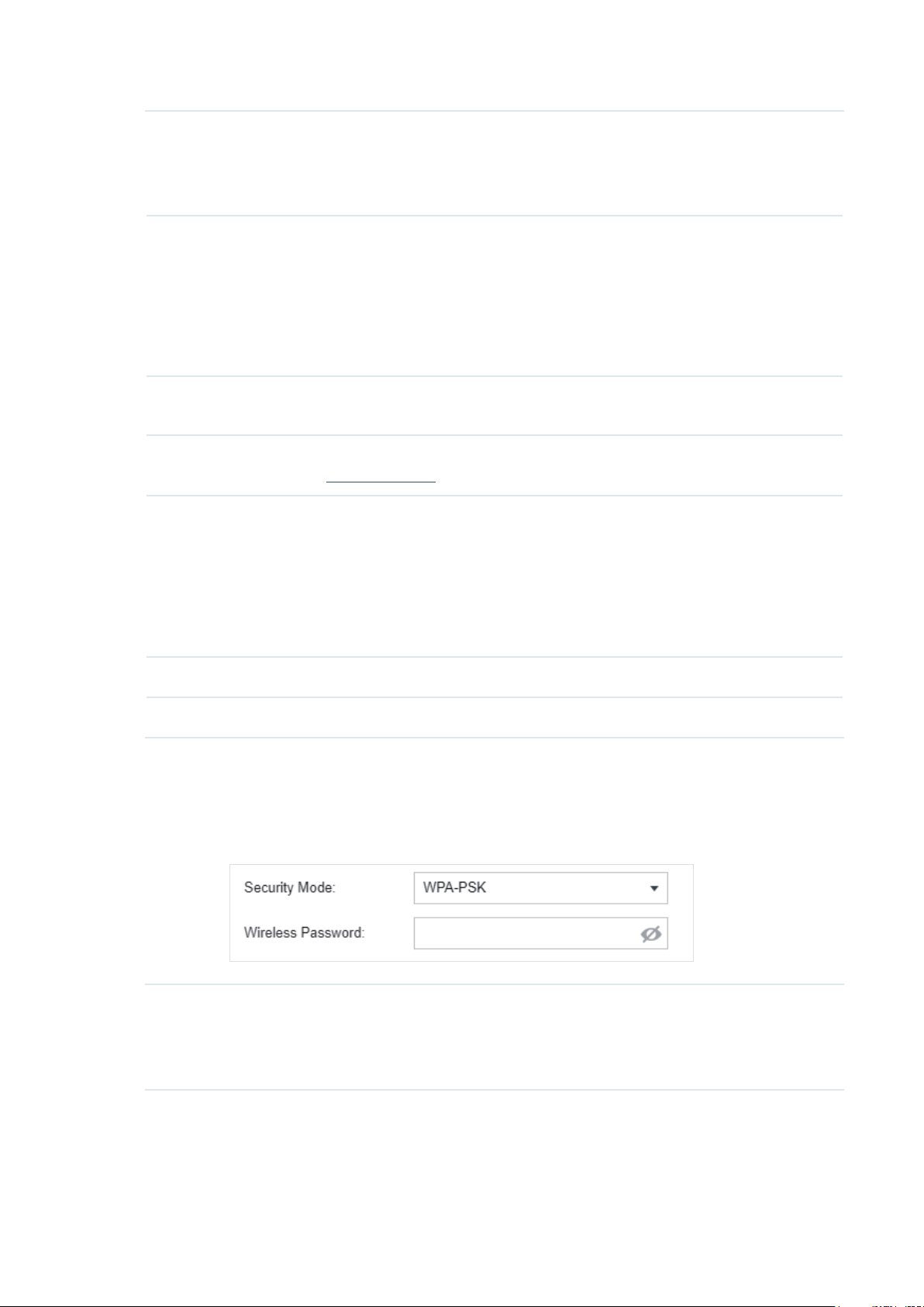
WPA-PSK
Based on a pre-shared key, WPA-PSK is characterized by high safety and simple settings and is
mostly used by common households and small businesses.
Wireless
Password
Configure the wireless password with ASCII or Hexadecimal characters.
For ASCII, the length should be between 8 and 63 characters with combination of
numbers, letters (case-sensitive) and common punctuations. For Hexadecimal, the
length should be 64 characters (case-insensitive, 0-9, a-f, A-F).
43
Page 50

Configure th advanced parameters in the following window.
Version Select the version of WPA-Enterprise.
Auto: The EAP will automatically choose the version used by each client device.
WPA/WPA2: Two versions of Wi-Fi Protected Access.
Encryption Select the Encryption type.
Auto: The default setting is Auto and the EAP will select TKIP or AES
automatically based on the client request.
TKIP: Temporal Key Integrity Protocol. TKIP is not supported in 802.11n mode,
802.11ac mode or 802.11n/ac mixed mode. If TKIP is applied in 802.11n,
802.11 ac or 802.11n/ac mixed mode, the clients may not be able to access the
wireless network of the EAP. If TKIP is applied in 11b/g/n mode (2.4GHz) or 11a/
n mode(5GHz), the device may work at a low transmission rate.
AES: Advanced Encryption Standard. We recommend that you select AES as
the encryption type for it is more secure than TKIP.
Group Key Update
Period
Specify a group key update period, which instructs the EAP how often it should
change the encryption keys. The value can be either 0 or 30~8640000 seconds.
0 means the encryption keys will not be changed all the time.
44
Page 51

SSID Broadcast With the option enabled, EAPs will broadcast the SSID to the nearby hosts, so
that those hosts can find the wireless network identified by this SSID. If this
option is disabled, users must enter the SSID manually to connect to the EAP.
The option is enabled by default.
Wireless VLAN With this option enabled, the EAP can work together with the switches
supporting 802.1Q VLAN. Traffic from the clients in different wireless networks
is added with different VLAN tags according to the VLAN settings of the
wireless networks. Then the wireless clients in different VLANs cannot directly
communicate with each other.
To set a wireless VLAN for the wireless network, enable the option and set a
VLAN ID in the Wireless VLAN ID.
Wireless VLAN ID Enter a VLAN ID for the wireless VLAN. Wireless networks with the same VLAN
ID are grouped to a VLAN. The value ranges from 1 to 4094.
Access Control Rule
Rate Limit With this option enabled, the download and upload rate of each client which
Download Limit With Rate Limit enabled, specify the limit of download rate. 0 means unlimited.
Upload Limit With Rate Limit enabled, specify the limit of upload rate. 0 means unlimited.
Select an Access Control rule for this SSID. For more information, refer to
Access Control
connects to the SSID will be limited to balance bandwidth usage. You can limit
the download and upload rate for some specific clients by configuring rate
limit in client list, refer to
details.
Note that the download and upload rate will be limited to the minimum of the
value configured in SSID, client and portal configuration.
.
Manage Clients in the Action Column
6. Click Apply.
3.1.2 Configure Advanced Wireless Parameters
Proper wireless parameters can improve the network's stability, reliability and communication
efficiency. The advanced wireless parameters consist of Fast Roaming, Beacon Interval, DTIM
to get more
Period, RTS Threshold, Fragmentation Threshold and Airtime Fairness.
To configure the advanced wireless parameters, follow the steps below.
1. Go to Wireless Settings > Advanced Wireless Setting.
45
Page 52

2. Enable Fast Roaming and configure the corresponding parameters.
Fast Roaming With this option enabled, 11k/v capable clients can have improved fast
roaming experience when moving among different APs.
Dual Band 11k Report With this feature disabled, the controller provides candidate AP report that
contains the APs in the same band as the clients. With this feature enabled,
the controller provides candidate AP report that contains the APs in both
2.4GHz and 5GHz bands.
Force-disassociation The controller dynamically monitors the link quality of every associated
client. When the client’s current link quality drops below the predefined
threshold and there are some other APs with better signal, the current AP
issues an 11v roaming suggestion to the client.
3. Click Apply.
With Force-disassociation disabled, the AP only issues a roaming
suggestion, but whether to roam or not is determined by the client.
With Force-disassociation enabled, the AP not only issues a roaming
suggestion but also disassociates the client after a while. Thus the client
is supported to re-associate to a better AP. This function is recommended
when there are sticky clients that don‘t roam.
46
Page 53

4. Select the band frequency .
5. Configure the following parameters.
Beacon Interval Beacons are transmitted periodically by the EAP to announce the presence of
a wireless network for the clients. Beacon Interval value determines the time
interval of the beacons sent by the device.
You can specify a value between 40 and 100ms. The default is 100ms.
DTIM Period The DTIM (Delivery Traffic Indication Message) is contained in some Beacon
frames. It indicates whether the EAP has buffered data for client devices. The
DTIM Period indicates how often the clients served by this EAP should check for
buffered data still on the EAP awaiting pickup.
You can specify the value between 1-255 Beacon Intervals. The default value
is 1, indicating clients check for buffered data on the EAP at every beacon. An
excessive DTIM interval may reduce the performance of multicast applications,
so we recommend that you keep it by default.
RTS Threshold RTS (Request to Send) can ensure efficient data transmission. When RTS is
activated, the client will send a RTS packet to EAP to inform that it will send data
before it send packets. After receiving the RTS packet, the EAP notices other
clients in the same wireless network to delay their transmitting of data and
informs the requesting client to send data, thus avoiding the conflict of packet.
If the size of packet is larger than the RTS Threshold, the RTS mechanism will be
activated.
If you specify a low threshold value, RTS packets are sent more frequently
and help the network recover from interference or collisions that might occur
on a busy network. However, it also consumes more bandwidth and reduces
the throughput of the packet. We recommend that you keep it by default. The
recommended and default value is 2347.
Fragmentation
Threshold
Airtime Fairness With this option enabled, each client connecting to the EAP can get the same
The fragmentation function can limit the size of packets transmitted over the
network. If a packet exceeds the Fragmentation Threshold, the fragmentation
function is activated and the packet will be fragmented into several packets.
Fragmentation helps improve network performance if properly configured.
However, too low fragmentation threshold may result in poor wireless
performance caused by the extra work of dividing up and reassembling of
frames and increased message traffic. The recommended and default value is
2346 bytes.
amount of time to transmit data, avoiding low-data-rate clients to occupy
too much network bandwidth and improving the network throughput. We
recommend that you enable this function under multi-rate wireless networks.
6. Click Apply.
3.1.3 Configure Band Steering
A client device that is capable of communicating on both the 2.4GHz and 5GHz frequency bands will
typically connect to the 2.4GHz band. However, if too many client devices are connected to an EAP
on the 2.4GHz band, the efficiency of communication will be diminished. Band Steering can steer
47
Page 54
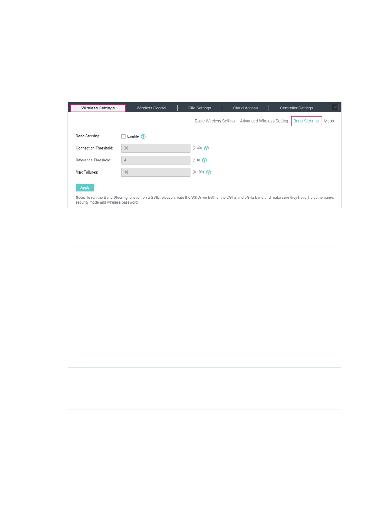
dual-band clients to the 5GHz frequency band which supports higher transmission rates and more
client devices, and thus to greatly improve the network quality.
To configure Band Steering, follow the steps below.
1. Go to Wireless Settings > Band Steering.
2. Check the box to enable the Band Steering function.
3. Configure the following parameters to balance the clients on both frequency bands:
Connection Threshold/
Difference Threshold
Max Failures If a client repeatedly attempts to associate with the EAP on the 5GHz band
Connection Threshold defines the maximum number of clients connected
to the 5GHz band. The value of Connection Threshold is from 2 to 40, and
the default is 20.
Difference Threshold defines the maximum difference between the
number of clients on the 5GHz band and 2.4GHz band. The value of
Difference Threshold is from 1 to 8, and the default is 4.
When the following two conditions are both met, the EAP prefers to refuse
the connection request on 5GHz band and no longer steers other clients
to the 5GHz band:
1. The number of clients on the 5GHz band reaches the Connection
Threshold value.
2. The difference between the number of clients on the 2.4GHz band and
5GHz band reaches the Difference Threshold value.
and the number of rejections reaches the value of Max Failures, the EAP
will accept the request.
The value is from 0 to 100, and the default is 10.
4. Click Apply.
3.1.4 Configure Mesh
Mesh is used to establish a wireless network or expand a wired network through wireless
connection on 5GHz radio band. In practical application, it can help users to conveniently deploy
APs without requiring Ethernet cable. After mesh network establishes, the EAPs can be configured
48
Page 55

and managed within Omada controller in the same way as wired EAPs. Meanwhile, because of
the ability to self-organize and self-configure, mesh also can efficiently reduce the configuration
overhead.
Note:
• EAP225-Outdoor with specific firmware (version 1.3 or above) and EAP225 V3 with specific firmware
(version 2.5.0 or above) are available for mesh function currently.
• Only the EAPs in the same site can establish a mesh network.
To understand how mesh can be used, the following terms used in Omada Controller will be
introduced:
Root AP: The AP is managed by Omada Controller with a wired data connection that can be
■
configured to relay data to and from mesh APs (Downlink AP).
Isolated AP: When the EAP which has been managed before by Omada Controller connects to
■
the network wirelessly and cannot reach the gateway, it goes into the Isolated state.
Mesh AP: An isolated AP will be mesh AP after establishing a wireless connection to the AP with
■
network access.
Uplink AP/Downlink AP: Among mesh APs, the AP that offers the wireless connection for
■
other APs is Uplink AP. A Root AP or an intermediate AP can be the Uplink AP. And the AP
that connects to the Uplink AP is called Downlink AP. An uplink AP can offer direct wireless
connection for 4 Downlink APs at most.
Wireless Uplink: The action that a Downlink AP connects to the uplink AP.
■
Hops: In a deployment that uses a root AP and more than one level of wireless uplink with
■
intermediate APs, the uplink tiers can be referred to by root, first hop, second hop and so on.
The hops cannot be more than 3.
In a basic mesh network as shown below, there is a root AP that is connected by Ethernet
cable, while other isolated APs have no wired data connection. Mesh allows the isolated APs to
communicate with pre-configured root AP on the network. Once powered up, factory default or
unadopted EAPs can sense the EAP in range and make itself available for adoption within the
Omada controller.
49
Page 56

Omada Controller
Internet
Wireless Uplink
Router (DHCP Server)
Wired LAN Connection
Host A (Controller Host) Switch
Root AP Mesh AP
(Hops: 1)
Mesh APs
(Hops: 2)
After all the EAPs are adopted, a mesh network is established. Then the EAPs connected to the
network wirelessly also can broadcast SSIDs and relay network traffic to and from the network
through the uplink AP.
To establish a mesh network, follow the steps below.
Enable Mesh Function.
■
Adopt the Root AP.
■
Set up wireless uplink by adopting APs in Pending (Wireless) or Isolated status.
■
1. Go to Wireless Settings > Mesh.
2. Check the box to enable the Mesh function.
3. Configure the following parameters to maintain the mesh network:
50
Page 57

Auto Failover Enable or disable Auto Failover.
Auto Failover is used to automatically maintain the mesh network for the
controller. With this feature enabled, the controller can automatically
select an uplink AP for the isolated EAP to establish Wireless Uplink. Thus
the controller will automatically select a new uplink AP for the mesh EAPs
when the original uplink fails.
Connectivity Detection Specify the method of Connection Detection.
In a mesh network, the APs can send ARP request packets to a fixed IP
address to test the connectivity. If the link fails, the status of these APs will
change to Isolated.
Auto (Recommended): Select this method and the mesh APs will send ARP
request packets to the default gateway for the detection.
Custom IP Address: Select this method and specify a desired IP address.
The mesh APs will send ARP request packets to the custom IP address
to test the connectivity. If the IP address of the AP is in different network
segments from the custom IP address, the AP will use the default gateway
IP address for the detection.
Full-Sector DFS With this feature enabled, when radar signals are detected on current
channel by one EAP, the other EAPs in the mesh network will be also
informed. Then all EAPs in the mesh network will switch to an alternate
channel.
4. Click Apply.
5. Go to Access Points > Pending and adopt the Root AP. Then the status of the Root AP will
change into Connected.
6. Install the EAP that will uplink the Root AP wirelessly. Make sure the intended location is within
the range of Root AP. The EAPs that is waiting for Wireless Uplink includes two cases: factory
default EAPs and EAPs that has been managed by Omada Controller before.
1 ) For the factory default EAP, after powering on the device, the EAP will be in Pending (Wireless)
status shown in the controller. Go to Access Points > Pending and adopt the EAPs in
Pending (Wireless) status.
51
Page 58

After adoption begins, the status of Pending (Wireless) EAP will become Adopting (Wireless) and
then Connected (Wireless). It should take roughly 2 minutes to show up Connected (Wireless)
within your controller.
2 ) For the EAP that has been managed by Omada Controller before and cannot reach the
gateway, it goes into Isolated status when it is discovered by controller again. Go to Access
Points > Isolated, click
.
The following page will shown, go to Mesh, then click to connect the Uplink AP.
Once adoption has finished, your device can be managed by the controller in the same way as a
wired EAP. You can click the EAP’s name on the Access Points tab to view and configure the mesh
parameters of the EAP on the pop-up window. Please refer to View Mesh Information of the EAP.
Tips:
• You can manually select the uplink AP that you want to connect in the uplink EAP list. To build a mesh
network with better performance, we recommend that you select the Uplink AP with the strongest signal,
least hop and least Downlink AP.
• You can enable Auto Failover to make the controller automatically select an uplink AP for the isolated EAP
to establish Wireless Uplink. And the controller will automatically select a new uplink AP for the mesh EAPs
when the original uplink fails.
52
Page 59

3.2 Access Control
Access Control is used to block or allow the clients to access specific subnets. To configure
Access Control rules, follow the steps below.
1. Go to Wireless Control > Access Control.
2. Click to add a new Access Control rule.
3. Configure the following parameters.
Rule Name Specify a name for this rule.
Rule Mode Select the mode for this rule.
Block: Select this mode to block clients to access the specific subnets.
Allow: Select this mode to allow clients to access the specific subnets.
Rule Members Specify the member subnets for this rule.
Subnets: Enter the subnet that will follow the rule mode in the format X.X.X.X/X
and click
Except Subnets: Enter the excepted subnet in the format X.X.X.X/X and click
. Up to 16 subnets can be added. The rule mode will not apply to the
subnet that is in both of the Subnets list and Except Subnets list.
. Up to 16 subnets can be added.
4. Click Apply.
53
Page 60

5. Go to Wireless Settings > Basic Wireless Setting and enable Access Control function of a
selected SSID.
3.3 Portal Authentication
Portal authentication enhances the network security by providing authentication service to the
clients that just need temporary access to the wireless network. Such clients have to log into a
web page to establish verification, after which they will access the network as guests. What's more,
you can customize the authentication login page and specify a URL which the newly authenticated
clients will be redirected to.
To configure Portal Authentication, go to Wireless Control > Portal and click
Then the following window will pop up:
.
These authentication methods are available: No Authentication, Simple Password, Local User,
Voucher, SMS, Facebook, External RADIUS Server and External Portal Server. The following
sections introduce how to configure each Portal authentication.
54
Page 61

3.3.1 No Authentication
With No Authentication configured, clients can access the network without any authentication.
Follow the steps below to configure No Authentication:
1. Go to Wireless Settings > Basic Wireless Settings and create an SSID for the Portal.
2. Go back to the Portal configuration page. In the Basic Info section, complete the basic settings
for the portal authentication.
Congure the following parameters:
Portal Name Specify a name for the Portal.
SSID Select an SSID for the Portal.
Authentication Type Select No Authentication.
Authentication
Timeout
Daily Limit With Daily Limit enabled, after authentication times out, the user cannot get
With Daily Limit disabled, the client's authentication will expire after the time
period you set and the client needs to log in again on the web authentication
page to access the network.
Options include 1 Hour, 8 Hours, 24 Hours, 7 Days and Custom. Custom
allows you to define the time in days, hours and minutes. The default value is
one hour.
With Daily Limit enabled, the client’s authentication will expire after the time
period you set and the client cannot log in again in the same day.
Options include 30 Minutes, 1 Hour, 2 Hours, 4 Hours and Custom. Custom
allows you to define the time in hours and minutes. The default value is 30
minutes.
authenticated again in the same day.
HTTPS Redirect With this function enabled, the unauthorized clients will be redirected to the
Portal page when they are trying to browse HTTPS websites.
With this function disabled, the unauthorized clients cannot browse HTTPS
websites and are not redirected to the Portal page.
55
Page 62

Redirect If you enable this function, the portal will redirect the newly authenticated
clients to the configured URL.
Redirect URL If the Redirect function above is enabled, enter the URL that a newly
authenticated client will be redirected to.
3. In the Login Page section, configure the login page for the Portal.
Congure the following parameters:
Background Select the background type. Two types are supported: Solid Color and
Picture.
Background Color If Solid Color is selected, configure your desired background color through
the color picker or by entering the RGB value manually.
Background Picture If Picture is selected, click the Choose button and select a picture from
your PC. Drag and scale the clipping region to edit the picture and click
Confirm.
Logo Picture Click the Choose button and select a picture from your PC. Drag and scale
the clipping region to edit the picture and click Confirm.
In addtion, you can click
include Middle, Upper and Lower.
and configure the logo position. The options
56
Page 63

Welcome Information Specify the welcome information.
In addtion, you can click
welcome information through the color picker or by entering the RGB value
manually.
Copyright Specify the copyright information.
In addtion, you can click
information through the color picker or by entering the RGB value manually.
and select your desired text color for the
and select your desired text color for Copyright
Terms of Service Enable or disable Terms of Service. With this option enabled, specify the
terms of service in the following box.
57
Page 64

Button
Click
Button Position: Set the position of the login button. The options include
Middle, Upper and Lower.
Button Color: Select your desired login button color through the color
picker or by entering the RGB value manually.
Button Text Color: Select your desired text color for the button through the
color picker or by entering the RGB value manually.
and configure the button.
4. In the Advertisement section, select whether to display advertisement pictures for users and
configure the related parameters.
Congure the following parameters:
Advertisement Specify whether to enable the Advertisement feature. With this feature
enabled, you can add advertisement pictures on the authentication page.
These advertisement pictures will be displayed before the login page
appears. You can also allow users to skip the advertisement by enabling
Allow Users To Skip Advertisement. The advertisement picture should
be less than 2MB. And only JPG, PNG, BMP, GIF and JPEG file types are
supported.
58
Page 65

Picture Resource Upload advertisement pictures. When several pictures are added, they will
be played in a loop.
Advertisement
Duration Time
Picture Carousel
Interval
Allow Users To Skip
Advertisement
5. Click Apply.
3.3.2 Simple Password
With this Simple Password configured, clients are required to enter the correct password to pass
the authentication.
Follow the steps below to configure No Simple Password Portal:
1. Go to Wireless Settings > Basic Wireless Settings and create an SSID for the Portal.
Specify how long the advertisement will be displayed for. For this duration,
the pictures will be played in a loop. If the duration time is not enough for all
the pictures, the rest will not be displayed.
Specify the picture carousel interval. For example, if this value is set as 5
seconds, the first picture will be displayed for 5 seconds, followed by the
second picture for 5 seconds, and so on.
Specify whether to enable this feature. With this feature enabled, the user
can click the Skip button to skip the advertisement.
2. Go back to the Portal configuration page. In the Basic Info section, complete the basic settings
for the portal authentication.
Congure the following parameters:
Portal Name Specify a name for the Portal.
SSID Select an SSID for the Portal.
Authentication Type Select Simple Password.
Password Set the password for authentication.
59
Page 66

Authentication
Timeout
HTTPS Redirect With this function enabled, the unauthorized clients will be redirected to the
Redirect If you enable this function, the portal will redirect the newly authenticated
Redirect URL If the Redirect function above is enabled, enter the URL that a newly
The client's authentication will expire after the time period you set and the
client needs to log in again on the web authentication page to access the
network.
Options include 1 Hour, 8 Hours, 24 Hours, 7 Days and Custom. Custom
allows you to define the time in days, hours and minutes. The default value is
one hour.
Portal page when they are trying to browse HTTPS websites.
With this function disabled, the unauthorized clients cannot browse HTTPS
websites and are not redirected to the Portal page.
clients to the configured URL.
authenticated client will be redirected to.
3. In the Login Page section, configure the login page for the Portal.
Congure the following parameters:
Background Select the background type. Two types are supported: Solid Color and
Picture.
Background Color If Solid Color is selected, configure your desired background color through
the color picker or by entering the RGB value manually.
Background Picture If Picture is selected, click the Choose button and select a picture from
your PC. Drag and scale the clipping region to edit the picture and click
Confirm.
60
Page 67

Logo Picture Click the Choose button and select a picture from your PC. Drag and scale
the clipping region to edit the picture and click Confirm.
In addtion, you can click
include Middle, Upper and Lower.
Welcome Information Specify the welcome information.
In addtion, you can click
welcome information through the color picker or by entering the RGB value
manually.
and configure the logo position. The options
and select your desired text color for the
Copyright Specify the copyright information.
In addtion, you can click
information through the color picker or by entering the RGB value manually.
Terms of Service Enable or disable Terms of Service. With this option enabled, specify the
terms of service in the following box.
and select your desired text color for Copyright
61
Page 68

Input Box
Click
Select your desired color for the input box through the color picker or by
entering the RGB value manually.
and configure the input box.
Button
Click
Button Position: Set the position of the login button. The options include
Middle, Upper and Lower.
Button Color: Select your desired login button color through the color
picker or by entering the RGB value manually.
Button Text Color: Select your desired text color for the button through the
color picker or by entering the RGB value manually.
and configure the button.
4. In the Advertisement section, select whether to display advertisement pictures for users and
configure the related parameters.
62
Page 69

Congure the following parameters:
Advertisement Specify whether to enable the Advertisement feature. With this feature
enabled, you can add advertisement pictures on the authentication page.
These advertisement pictures will be displayed before the login page
appears. You can also allow users to skip the advertisement by enabling
Allow Users To Skip Advertisement. The advertisement picture should
be less than 2MB. And only JPG, PNG, BMP, GIF and JPEG file types are
supported.
Picture Resource Upload advertisement pictures. When several pictures are added, they will
be played in a loop.
Advertisement
Duration Time
Picture Carousel
Interval
Allow Users To Skip
Advertisement
5. Click Apply.
3.3.3 Local User
With this Local User configured, clients are required to enter the correct username and password of
the login account to pass the authentication. You can create multiple accounts and assign different
accounts for different users.
Configure Local User Portal
Specify how long the advertisement will be displayed for. For this duration,
the pictures will be played in a loop. If the duration time is not enough for all
the pictures, the rest will not be displayed.
Specify the picture carousel interval. For example, if this value is set as 5
seconds, the first picture will be displayed for 5 seconds, followed by the
second picture for 5 seconds, and so on.
Specify whether to enable this feature. With this feature enabled, the user
can click the Skip button to skip the advertisement.
Follow the steps below to configure Local User Portal:
1. Go to Wireless Settings > Basic Wireless Settings and create an SSID for the Portal.
2. Go back to the Portal configuration page. In the Basic Info section, complete the basic settings
for the portal authentication.
63
Page 70

Congure the following parameters:
Portal Name Specify a name for the Portal.
SSID Select an SSID for the Portal.
Authentication Type Select Local User.
User Management
HTTPS Redirect With this function enabled, the unauthorized clients will be redirected to the
Redirect If you enable this function, the portal will redirect the newly authenticated
Redirect URL If the Redirect function above is enabled, enter the URL that a newly
You can click this button to configure user accounts for authentication later.
Please refer to
Portal page when they are trying to browse HTTPS websites.
With this function disabled, the unauthorized clients cannot browse HTTPS
websites and are not redirected to the Portal page.
clients to the configured URL.
authenticated client will be redirected to.
Create Local User Accounts
.
3. In the Login Page section, configure the login page for the Portal.
Congure the following parameters:
Background Select the background type. Two types are supported: Solid Color and
Picture.
64
Page 71

Background Color If Solid Color is selected, configure your desired background color through
the color picker or by entering the RGB value manually.
Background Picture If Picture is selected, click the Choose button and select a picture from
your PC. Drag and scale the clipping region to edit the picture and click
Confirm.
Logo Picture Click the Choose button and select a picture from your PC. Drag and scale
the clipping region to edit the picture and click Confirm.
In addtion, you can click
include Middle, Upper and Lower.
Welcome Information Specify the welcome information.
In addtion, you can click
welcome information through the color picker or by entering the RGB value
manually.
and configure the logo position. The options
and select your desired text color for the
Copyright Specify the copyright information.
In addtion, you can click
information through the color picker or by entering the RGB value manually.
and select your desired text color for Copyright
65
Page 72
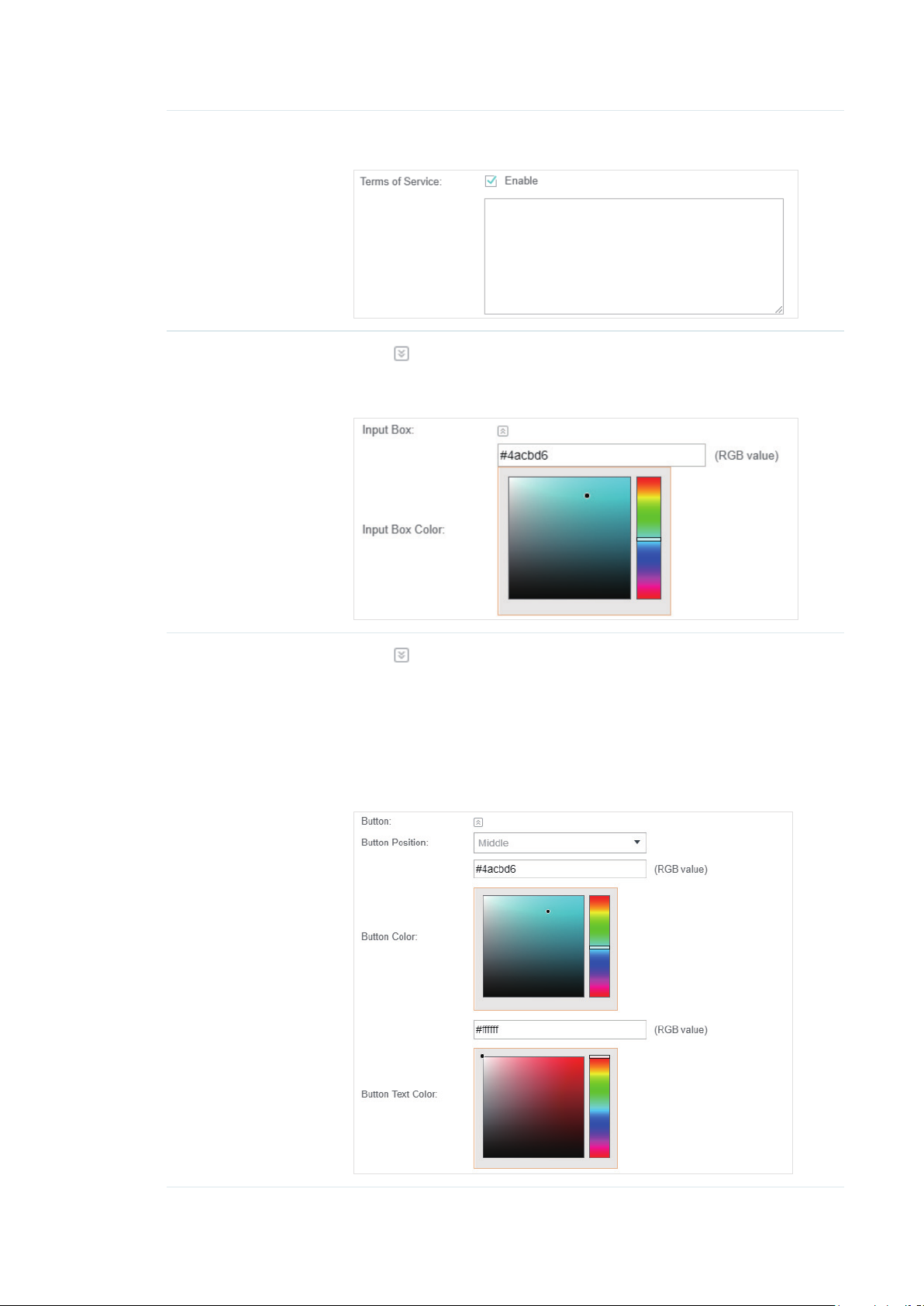
Terms of Service Enable or disable Terms of Service. With this option enabled, specify the
terms of service in the following box.
Input Box
Button
Click
Select your desired color for the input box through the color picker or by
entering the RGB value manually.
Click
Button Position: Set the position of the login button. The options include
Middle, Upper and Lower.
Button Color: Select your desired login button color through the color
picker or by entering the RGB value manually.
Button Text Color: Select your desired text color for the button through the
color picker or by entering the RGB value manually.
and configure the input box.
and configure the button.
66
Page 73

4. In the Advertisement section, select whether to display advertisement pictures for users and
configure the related parameters.
Congure the following parameters:
Advertisement Specify whether to enable the Advertisement feature. With this feature
enabled, you can add advertisement pictures on the authentication page.
These advertisement pictures will be displayed before the login page
appears. You can also allow users to skip the advertisement by enabling
Allow Users To Skip Advertisement. The advertisement picture should
be less than 2MB. And only JPG, PNG, BMP, GIF and JPEG file types are
supported.
Picture Resource Upload advertisement pictures. When several pictures are added, they will
be played in a loop.
Advertisement
Duration Time
Picture Carousel
Interval
Allow Users To Skip
Advertisement
Specify how long the advertisement will be displayed for. For this duration,
the pictures will be played in a loop. If the duration time is not enough for all
the pictures, the rest will not be displayed.
Specify the picture carousel interval. For example, if this value is set as 5
seconds, the first picture will be displayed for 5 seconds, followed by the
second picture for 5 seconds, and so on.
Specify whether to enable this feature. With this feature enabled, the user
can click the Skip button to skip the advertisement.
5. Click Apply.
Create Local User Accounts
Follow the steps below to create the user accounts for authentication:
1. In the Basic Info section on the portal configuration page, click User Management. The
management page will appear. Go to the User page and click
.
67
Page 74

2. The following window will pop up. Configure the required parameters and click Apply.
Congure the following parameters:
Username Specify the username. The username should not be the same as any
existing one.
Password Specify the password. Users will be required to enter the username and
password when they attempt to access the network.
Authentication
Timeout
MAC Address Binding
Type
Specify the authentication timeout for formal users. After timeout, the users
need to log in again on the web authentication page to access the network.
There are three types of MAC binding: No Binding, Static Binding and
Dynamic Binding.
Static Binding: Specify a MAC address for this user account. Then only the
user with the this MAC address can use the username and password to
pass the authentication.
Dynamic Binding: The MAC address of the first user that passes the
authentication will be bound. Then only this user can use the username and
password to pass the authentication.
68
Page 75

Maximum Users Specify the maximum number of users able to use this account to pass the
authencitation.
Name Specify a name for identification.
Telephone Specify a telephone number for identification.
Rate Limit (Download) Select whether to enable download rate limit. With this option enabled, you
can specify the limit of download rate.
Rate Limit (Upload) Select whether to enable upload rate limit. With this option enabled, you
can specify the limit of upload rate.
Traffic Limit Select whether to enable traffic limit. With this option enabled, you can
specify the total traffic limit for the user. Once the limit is reached, the user
can no longer use this account to access the network.
3. In the same way, you can add more user accounts. The created user accounts will be displayed
in the list. Users can use the username and password of the account to pass the portal
authentication.
By default, the account Status is
You can also click this button to disable the user account. The icon will be changed to
, which means that the user account is enabled and valid.
, which
means that the user account is disabled.
Additionally, you can click to backup all the user account information into a CSV
le or XLS le and save the le to your PC. If needed, you can click
and select the
le to import the account information to the list.
Note:
Using Excel to open the CSV file may cause some numerical format changes, and the number may be displayed
incorrectly. If you use Excel to edit the CSV file, please set the cell format as text.
Manage the Guests
On the Guest page, you can view the information of clients that have passed the portal
authentication and manage the clients.
69
Page 76

You can select an icon to execute the corresponding operation:
Disconnect client.
Extend the effective time.
Create Operator Accounts
Operator account can be used to remotely manage the Local User Portal and Voucher Portal. Other
users can visit the URL https://Omada Controller Host’s IP Address:8043/hotspot (For example:
https://192.168.0.64:8043/hotspot) and use the Operator account to enter the portal management
page.
Note:
• Make sure the host that is used to enter the portal management page with operator account can visit the
Controller host.
• Only the user that log in to the controller with the administrator role can add or remove the operator
account for portal management.
• The users who enter the portal management page by operator account can only create local user accounts
and vouchers and manage the clients.
Follow the steps below to create Operator account.
1. Go to the Operator page.
2. Click and the following window will pop up.
3. Specify the Name, Password and Notes of the Operator account.
4. Select Site Privileges from the drop-down list (multiple options available) for the Operator
account.
5. Click Apply to create an Operator account. Then other users can use this account to enter the
hotspot management page.
70
Page 77

3.3.4 Voucher
With Voucher configured, you can distribute the vouchers automatically generated by the Omada
Controller to the clients. Clients can use the vouchers to access the network.
Configure Voucher Portal
Follow the steps below to configure Voucher Portal:
1. Go to Wireless Settings > Basic Wireless Settings and create an SSID for the Portal.
2. Go back to the Portal configuration page. In the Basic Info section, complete the basic settings
for the portal authentication.
Congure the following parameters:
Portal Name Specify a name for the Portal.
SSID Select an SSID for the Portal.
Authentication Type Select Voucher.
User Management
HTTPS Redirect With this function enabled, the unauthorized clients will be redirected to the
Redirect If you enable this function, the portal will redirect the newly authenticated
Redirect URL If the Redirect function above is enabled, enter the URL that a newly
You can click this button to configure vouchers for authentication later.
Please refer to
Portal page when they are trying to browse HTTPS websites.
With this function disabled, the unauthorized clients cannot browse HTTPS
websites and are not redirected to the Portal page.
clients to the configured URL.
authenticated client will be redirected to.
Create Vouchers
.
71
Page 78

3. In the Login Page section, configure the login page for the Portal.
Congure the following parameters:
Background Select the background type. Two types are supported: Solid Color and
Picture.
Background Color If Solid Color is selected, configure your desired background color through
the color picker or by entering the RGB value manually.
Background Picture If Picture is selected, click the Choose button and select a picture from
your PC. Drag and scale the clipping region to edit the picture and click
Confirm.
Logo Picture Click the Choose button and select a picture from your PC. Drag and scale
the clipping region to edit the picture and click Confirm.
In addtion, you can click
include Middle, Upper and Lower.
Welcome Information Specify the welcome information.
In addtion, you can click
welcome information through the color picker or by entering the RGB value
manually.
and configure the logo position. The options
and select your desired text color for the
72
Page 79

Copyright Specify the copyright information.
In addtion, you can click
information through the color picker or by entering the RGB value manually.
Terms of Service Enable or disable Terms of Service. With this option enabled, specify the
terms of service in the following box.
and select your desired text color for Copyright
Input Box
Click
Select your desired color for the input box through the color picker or by
entering the RGB value manually.
and configure the input box.
73
Page 80

Button
Click
Button Position: Set the position of the login button. The options include
Middle, Upper and Lower.
Button Color: Select your desired login button color through the color
picker or by entering the RGB value manually.
Button Text Color: Select your desired text color for the button through the
color picker or by entering the RGB value manually.
and configure the button.
4. In the Advertisement section, select whether to display advertisement pictures for users and
configure the related parameters.
Congure the following parameters:
Advertisement Specify whether to enable the Advertisement feature. With this feature
enabled, you can add advertisement pictures on the authentication page.
These advertisement pictures will be displayed before the login page
appears. You can also allow users to skip the advertisement by enabling
Allow Users To Skip Advertisement. The advertisement picture should
be less than 2MB. And only JPG, PNG, BMP, GIF and JPEG file types are
supported.
Picture Resource Upload advertisement pictures. When several pictures are added, they will
be played in a loop.
Advertisement
Duration Time
Specify how long the advertisement will be displayed for. For this duration,
the pictures will be played in a loop. If the duration time is not enough for all
the pictures, the rest will not be displayed.
74
Page 81

Picture Carousel
Interval
Specify the picture carousel interval. For example, if this value is set as 5
seconds, the first picture will be displayed for 5 seconds, followed by the
second picture for 5 seconds, and so on.
Allow Users To Skip
Advertisement
Specify whether to enable this feature. With this feature enabled, the user
can click the Skip button to skip the advertisement.
5. Click Apply.
Create Vouchers
Follow the steps below to create vouchers for authentication:
1. In the Basic Info section, click Voucher Manager. The voucher management page will appear. Go
to the Voucher page and click
2. The following window will pop up. Configure the required parameters and click Apply.
.
75
Page 82

Congure the following parameters:
Code Length Specify the length of the voucher codes to be created.
Amount Enter the voucher amount to be generated.
Type Select Single Use or Multi Use.
Single Use means one voucher can only be distributed to one client. Multi Use
means one voucher can be distributed to several clients, who can use the
same voucher to access the network at the same time.
If you select Multi Use, enter the value of Max Users. When the number of
clients who are connected to the network with the same voucher reaches the
value, no more clients can use this voucher to access the network.
Duration Select the period of validity of the Voucher.
The options include 8 hours, 2 days and User-defined. The period of valid of
the voucher is reckoned from the time when it is used for the first time.
Rate Limit
(Download)
Rate Limit (Upload) Select whether to enable upload rate limit. With this option enabled, you can
Traffic Limit Specify the total traffic limit for one voucher. Once the limit is reached, the
Notes Enter a description for the Voucher (optional).
Select whether to enable download rate limit. With this option enabled, you
can specify the limit of download rate.
specify the limit of upload rate.
client can no longer access the network using the voucher.
3. The Vouchers will be generated and displayed on the page.
4. Click to print a single voucher; click to print your selected vouchers;
click
to print all unused vouchers.
76
Page 83

5. Distribute the vouchers to clients, and then they can use the codes to pass authentication.
6. When the vouchers are invalid, you can click
delete the selected vouchers.
to delete the Voucher or click to
Manage the Guests
On the Guest page, you can view the information of clients that have passed the portal
authentication and manage the clients.
You can select an icon to execute the corresponding operation:
Restrict the client to access the network.
Extend the effective time.
Create Operator Accounts
Operator account can be used to remotely manage the Local User Portal and Voucher Portal. Other
users can visit the URL https://Omada Controller Host’s IP Address:8043/hotspot (For example:
https://192.168.0.64:8043/hotspot) and use the Operator account to enter the portal management
page.
77
Page 84

Note:
• Make sure the host that is used to enter the portal management page with operator account can visit the
Controller host.
• Only the user that log in to the controller with the administrator role can add or remove the operator
account for portal management.
• The users who enter the portal management page by operator account can only create local user accounts
and vouchers and manage the clients.
Follow the steps below to create Operator account.
1. Go to the Operator page.
2. Click and the following window will pop up.
3. Specify the Name, Password and Notes of the Operator account.
4. Select Site Privileges from the drop-down list (multiple options available) for the Operator
account.
5. Click Apply to create an Operator account. Then other users can use this account to enter the
hotspot administrative system.
3.3.5 SMS
With SMS portal configured, client can get verification codes using their mobile phones and enter
the received codes to pass the authentication.
Follow the steps below to configure SMS Portal:
1. Go to www.twilio.com/try-twilio and get a Twilio account. Buy the Twilio service for SMS. Then
get the account information, including ACCOUNT SID, AUTH TOKEN and Phone number.
2. Go to Wireless Settings > Basic Wireless Settings and create an SSID for the Portal.
3. Go back to the Portal configuration page. In the Basic Info section, complete the basic settings
for the portal authentication.
78
Page 85

Congure the following parameters:
Portal Name Specify a name for the Portal.
SSID Select an SSID for the Portal.
Authentication Type Select SMS.
Twilio SID Enter the Account SID for Twilio API Credentials.
Auth Token Enter the Authentication Token for Twilio API Credentials.
Phone Number Enter the phone number that is used to send verification messages to the
clients.
Maximum Users A telephone can get several codes via messages one by one, and different
clients can use different codes to pass the authentication. However, the
number of clients that is allowed to be authenticated using the same
telephone at the same time has a upper limit.
Specify the upper limit in this field.
Authentication
Timeout
Preset Country Code Set the default country code that will be filled automatically on the
HTTPS Redirect With this function enabled, the unauthorized clients will be redirected to the
The client's authentication will expire after the time period you set and the
client needs to log in again on the web authentication page to access the
network.
Options include 1 Hour, 8 Hours, 24 Hours, 7 Days and Custom. Custom
allows you to define the time in days, hours and minutes. The default value is
one hour.
authentication page.
Portal page when they are trying to browse HTTPS websites.
With this function disabled, the unauthorized clients cannot browse HTTPS
websites and are not redirected to the Portal page.
79
Page 86
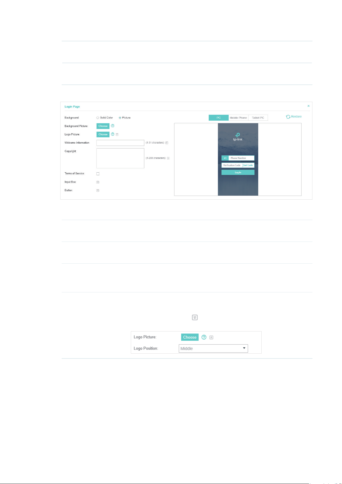
Redirect If you enable this function, the portal will redirect the newly authenticated
clients to the configured URL.
Redirect URL If the Redirect function above is enabled, enter the URL that a newly
authenticated client will be redirected to.
4. In the Login Page section, configure the login page for the Portal.
Congure the following parameters:
Background Select the background type. Two types are supported: Solid Color and
Picture.
Background Color If Solid Color is selected, configure your desired background color through
the color picker or by entering the RGB value manually.
Background Picture If Picture is selected, click the Choose button and select a picture from
your PC. Drag and scale the clipping region to edit the picture and click
Confirm.
Logo Picture Click the Choose button and select a picture from your PC. Drag and scale
the clipping region to edit the picture and click Confirm.
In addtion, you can click
include Middle, Upper and Lower.
and configure the logo position. The options
80
Page 87

Welcome Information Specify the welcome information.
In addtion, you can click
welcome information through the color picker or by entering the RGB value
manually.
Copyright Specify the copyright information.
In addtion, you can click
information through the color picker or by entering the RGB value manually.
and select your desired text color for the
and select your desired text color for Copyright
Terms of Service Enable or disable Terms of Service. With this option enabled, specify the
terms of service in the following box.
81
Page 88

Input Box
Click
Select your desired color for the input box through the color picker or by
entering the RGB value manually.
and configure the input box.
Button
Click
Button Position: Set the position of the login button. The options include
Middle, Upper and Lower.
Button Color: Select your desired login button color through the color
picker or by entering the RGB value manually.
Button Text Color: Select your desired text color for the button through the
color picker or by entering the RGB value manually.
and configure the button.
5. In the Advertisement section, select whether to display advertisement pictures for users and
configure the related parameters.
82
Page 89

Congure the following parameters:
Advertisement Specify whether to enable the Advertisement feature. With this feature
enabled, you can add advertisement pictures on the authentication page.
These advertisement pictures will be displayed before the login page
appears. You can also allow users to skip the advertisement by enabling
Allow Users To Skip Advertisement. The advertisement picture should
be less than 2MB. And only JPG, PNG, BMP, GIF and JPEG file types are
supported.
Picture Resource Upload advertisement pictures. When several pictures are added, they will
be played in a loop.
Advertisement
Duration Time
Picture Carousel
Interval
Allow Users To Skip
Advertisement
6. Click Apply.
For more details about how to configure SMS Portal, you can go to https://www.tp-link.com/en/
configuration-guides.html and download the configuration guide for SMS Portal.
3.3.6 Facebook
With Facebook Portal configured, when clients connect to your Wi-Fi, they will be
redirected to your Facebook page. To access the internet, clients need to pass the
authentication on the page.
Specify how long the advertisement will be displayed for. For this duration,
the pictures will be played in a loop. If the duration time is not enough for all
the pictures, the rest will not be displayed.
Specify the picture carousel interval. For example, if this value is set as 5
seconds, the first picture will be displayed for 5 seconds, followed by the
second picture for 5 seconds, and so on.
Specify whether to enable this feature. With this feature enabled, the user
can click the Skip button to skip the advertisement.
Note:
Omada Controller will automatically create Free Authentication Policy entries for the Facebook Portal. You don’t
need to create them manually.
Follow the steps below to configure Facebook Portal:
1. Go to www.facebook.com and get a Facebook account. Create your Facebook page according
to your needs.
2. Go to Wireless Settings > Basic Wireless Settings and create an SSID for the Portal.
3. Go back to the Portal configuration page. In the Basic Info section, complete the settings for the
portal authentication.
83
Page 90

Congure the following parameters:
Portal Name Specify a name for the Portal.
SSID Select an SSID for the Portal.
Authentication Type Select Facebook.
Facebook Page
Configuration
Facebook Checkin
Location
HTTPS Redirect With this function enabled, the unauthorized clients will be redirected to the
Click this button to specify the Facebook Page.
If the Facebook page is successfully got by the Omada Controller, the name
of the Facebook page will be displayed here.
Portal page when they are trying to browse HTTPS websites.
With this function disabled, the unauthorized clients cannot browse HTTPS
websites and are not redirected to the Portal page.
For more details about how to configure Facebook Portal, you can go to https://www.tp-link.com/
en/configuration-guides.html and download the configuration guide for Facebook Portal.
3.3.7 External RADIUS Server
If you have a RADIUS server, you can configure External RADIUS Server Portal. With this type of
portal, you can get two types of portal customization: Local Web Portal and External Web Portal.
The authentication login page of Local Web Portal is provided by the built-in portal server of the
controller. The External Web Portal is provided by external portal server.
Note:
Omada Controller will automatically create Free Authentication Policy entries for the External RADIUS Portal.
Follow the steps below to configure External RADIUS Server Portal:
1. Go to Wireless Settings > Basic Wireless Settings and create an SSID for the Portal.
2. Go back to the Portal configuration page. In the Basic Info section, complete the basic settings
for the portal authentication.
84
Page 91

Congure the following parameters:
Portal Name Specify a name for the Portal.
SSID Select an SSID for the Portal.
Authentication Type Select External RADIUS Server.
Authentication Timeout The client’s authentication will expire after the time period you set and
the client needs to log in again on the web authentication page to access
the network.
Options inclde 1 Hour, 8 Hours, 24 Hours, 7 Days, Custom. Custom
allows you to define the time in days, hours, and minutes. The default
value is one hour.
RADIUS Server IP Enter the IP address of the RADIUS server.
RADIUS Port Enter the port number you have set on the RADIUS server.
RADIUS Password Enter the password you have set on the RADIUS server.
Authentication Mode Select the authentication protocol for the RADIUS server. Two
authentication protocols are available: PAP and CHAP.
85
Page 92

NAS ID Configure a Network Access Server Identifier (NAS ID) using 1 to 64
characters on the portal. The NAS ID is sent to the RADIUS server by the
controller through an authentication request packet. With the NAS ID
which classifies users to different groups, the RADIUS server can send a
customized authentication response. The default value is TP-Link.
RADIUS Accounting Enable or disable RADIUS Accounting feature.
Accounting Server IP Enter the IP address of the accounting server.
Accounting Server Port Enter the port number of the accounting server. The default port number
is 1813.
Accounting Server
Password
Interim Update With this option enabled, you can specify the duration between
Interim Update Interval With Interim Update enabled, specify the appropriate duration between
Portal Customization Select Local Web Portal or External Web Portal.
Enter the shared secret key of the accounting server.
accounting information updates. By default, the function is disabled.
Enter the appropriate duration between updates for EAPs in Interim
Update Interval.
updates for EAPs. The default duration is 600 seconds.
Local Web Portal: If this option is selected, refer to step 3 to configure
the login page and step 4 to configure the advertisement.
External Web Portal: If this option is selected, follow the steps below.
1. Configure the external RADIUS server.
2. Enter the authentication login page’s URL provided by the external
portal server in the External Web Portal URL field.
Note that you should update the External Web Portal after you upgrade
your controller with old version to version 3.1.4 or above. Otherwise, the
External Web Portal will not take effect.
HTTPS Redirect With this function enabled, the unauthorized clients will be redirected to
the Portal page when they are trying to browse HTTPS websites.
With this function disabled, the unauthorized clients cannot browse
HTTPS websites and are not redirected to the Portal page.
Redirect If you enable this function, the portal will redirect the newly authenticated
clients to the configured URL.
It is disabled by default.
Redirect URL If the Redirect function above is enabled, enter the URL that a newly
authenticated client will be redirected to.
3. Local Web Portal is configured, configure the login page for the Portal in the Login Page section.
86
Page 93

Congure the following parameters:
Background Select the background type. Two types are supported: Solid Color and
Picture.
Background Color If Solid Color is selected, configure your desired background color through
the color picker or by entering the RGB value manually.
Background Picture If Picture is selected, click the Choose button and select a picture from
your PC. Drag and scale the clipping region to edit the picture and click
Confirm.
Logo Picture Click the Choose button and select a picture from your PC. Drag and scale
the clipping region to edit the picture and click Confirm.
In addtion, you can click
include Middle, Upper and Lower.
Welcome Information Specify the welcome information.
In addtion, you can click
welcome information through the color picker or by entering the RGB value
manually.
and configure the logo position. The options
and select your desired text color for the
87
Page 94

Copyright Specify the copyright information.
In addtion, you can click
information through the color picker or by entering the RGB value manually.
Terms of Service Enable or disable Terms of Service. With this option enabled, specify the
terms of service in the following box.
and select your desired text color for Copyright
Input Box
Click
Select your desired color for the input box through the color picker or by
entering the RGB value manually.
and configure the input box.
88
Page 95

Button
Click
Button Position: Set the position of the login button. The options include
Middle, Upper and Lower.
Button Color: Select your desired login button color through the color
picker or by entering the RGB value manually.
Button Text Color: Select your desired text color for the button through the
color picker or by entering the RGB value manually.
and configure the button.
4. If Local Web Portal is configured, select whether to display advertisement pictures for users and
configure the related parameters in the Advertisement section, .
Congure the following parameters:
Advertisement Specify whether to enable the Advertisement feature. With this feature
enabled, you can add advertisement pictures on the authentication page.
These advertisement pictures will be displayed before the login page
appears. You can also allow users to skip the advertisement by enabling
Allow Users To Skip Advertisement. The advertisement picture should
be less than 2MB. And only JPG, PNG, BMP, GIF and JPEG file types are
supported.
Picture Resource Upload advertisement pictures. When several pictures are added, they will
be played in a loop.
Advertisement
Duration Time
Specify how long the advertisement will be displayed for. For this duration,
the pictures will be played in a loop. If the duration time is not enough for all
the pictures, the rest will not be displayed.
89
Page 96

Picture Carousel
Interval
Specify the picture carousel interval. For example, if this value is set as 5
seconds, the first picture will be displayed for 5 seconds, followed by the
second picture for 5 seconds, and so on.
Allow Users To Skip
Advertisement
Specify whether to enable this feature. With this feature enabled, the user
can click the Skip button to skip the advertisement.
5. Click Apply.
3.3.8 External Portal Server
The option of External Portal Server is designed for the developers. They can customized their
own authentication type according to the interface provided by Omada Controller, e.g. message
authentication and WeChat authentication etc.
1. Go to Wireless Settings > Basic Wireless Settings and create an SSID for the Portal.
2. Go back to the Portal configuration page. In the Basic Info section, complete the settings for the
portal authentication.
Portal Name Specify a name for the Portal.
SSID Select an SSID for the Portal.
Authentication Type Select External Portal Server.
External Portal Server Enter the complete authentication URL that redirect to an external
portal server, for example:
http://192.168.0.147:8880/portal/index.php or http://192.168.0.147/
portal/index.html
HTTPS Redirect With this function enabled, the unauthorized clients will be redirected
to the Portal page when they are trying to browse HTTPS websites.
With this function disabled, the unauthorized clients cannot browse
HTTPS websites and are not redirected to the Portal page.
3. Click Apply.
90
Page 97

3.4 Free Authentication Policy
Free Authentication Policy allows some specified clients to access the network resources without
authentication. Follow the steps below to add free authentication policy.
1. Go to Wireless Control > Free Authentication Policy.
2. Click and the following window will pop up.
3. Configure the following parameters. When all conditions are met, the client can access the
network without authentication.
91
Page 98

Policy Name Specify a name for the policy.
Match Mode Select the match mode for the policy. Two options are provided:
URL: With this option selected, configure an URL that is allowed to be visited
by the clients without authentication.
IP-MAC Based: With this option selected, configure Source IP Range,
Destination IP Range, Source MAC and Destination MAC to specify the
specific clients and service that will follow the Free Authentication feature.
URL Set the URL.
Source IP Range Set the Source IP Range with the subnet and mask length of the clients.
Destination IP Range Set the Destination IP Range with the subnet and mask length of the server.
Source MAC Set the MAC address of client.
Destination Port Enter the port the service uses.
Status Check the box to enable the policy.
4. Click Apply and the policy is successfully added.
3.5 MAC Filter
MAC filter can be used to allow or block the listed clients to access the network. Thereby it can
effectively control the client's access to the wireless network.
Follow the steps below to configure MAC Filter.
1. Go to Wireless Control > MAC Filter to add MAC Filter group and group members.
1 ) Click and specify a name for the group.
2 ) Click Apply and the group will be successfully added as shown below.
92
Page 99

3 ) Click and enter a MAC address in the format as shown below.
4 ) Click Apply to add the MAC address into the MAC lter group.
2. You can add more groups or members according to your need.
Note:
You can click to export the group members to a excel file and save the file on your PC. If
needed, you can also click
to import the group members to the Omada Controller.
3. Go to Wireless Control > MAC Filter Association to associate the added MAC Filter group with
SSID.
93
Page 100

1 ) Check the box and click Apply to enable MAC Filtering function.
2 ) Select a band frequency (2.4GHz or 5GHz) and a WLAN group.
3 ) In the MAC Filter Name column of the specied SSID, select a MAC Filter group in the drop-
down list. Then select Allow/Deny in the Action column to allow/deny the clients in the MAC
Filter group to access the network.
4 ) Click Apply in the Setting column.
3.6 Scheduler
With the Scheduler, the EAPs or its’ wireless network can automatically turn on or off at the time you
set. For example, you can use this feature to schedule the radio to operate only during the office
working time in order to achieve security goals and reduce power consumption. You can also use
the Scheduler to make clients can only access the wireless network during the time period you set
in the day.
Follow the steps below to configure Scheduler.
1. Go to Wireless Control > Scheduler.
1 ) Click and specify a name for the prole.
94
 Loading...