

Page 1

1910012138
REV2.1.0
User Guide
HD Pan/Tilt Wi-Fi Camera
NC450
Page 2

CONTENTS
Chapter 1 About This Guide ................................................................................... 1
1.1 Conventions ................................................................................................................... 1
1.2 Overview of This Guide ................................................................................................. 1
1.3 More Info ....................................................................................................................... 2
Chapter 2 Get to Know Your Camera ..................................................................... 3
2.1 Product Overview .......................................................................................................... 3
2.2 Panel Appearance ......................................................................................................... 3
2.2.1 Front Panel......................................................................................................... 3
2.2.2 Rear Panel ......................................................................................................... 4
Chapter 3 Set Up Your Camera .............................................................................. 6
3.1 Set up the Camera with the tpCamera App .................................................................. 6
3.2 Position Your Camera .................................................................................................... 8
Chapter 4 Configure Your Camera ........................................................................ 11
4.1 Log in to Your Camera.................................................................................................. 11
4.2 Live View ..................................................................................................................... 13
4.3 Basic ............................................................................................................................ 15
4.3.1 Basic > Status .................................................................................................. 15
4.3.2 Basic > Network ............................................................................................... 17
4.3.3 Basic > Wireless Connection ........................................................................... 18
4.3.4 Basic > Cloud Setting ...................................................................................... 20
4.3.5 Basic > LED ..................................................................................................... 21
4.4 Advanced ..................................................................................................................... 22
4.4.1 Advanced > Status ........................................................................................... 22
4.4.2 Advanced > Network ........................................................................................ 22
4.4.3 Advanced > Wireless Connection .................................................................... 26
4.4.4 Advanced > Cloud Setting ............................................................................... 27
4.4.5 Advanced > Video ............................................................................................ 27
4.4.6 Advanced > Sound Detection .......................................................................... 29
4.4.7 Advanced > Motion Detection .......................................................................... 30
4.4.8 Advanced > SD Card ....................................................................................... 31
4.4.9 Advanced > Notification Delivery ..................................................................... 33
4.4.10 Advanced > LED .............................................................................................. 35
4.5 System ......................................................................................................................... 35
4.5.1 Account ............................................................................................................ 35
4.5.2 Date/Time ......................................................................................................... 37
4.5.3 Management .................................................................................................... 39
4.5.4 System Log ...................................................................................................... 41
Page 3
NC450
Contents to be emphasized and texts on the web page are in teal,
Chapter
Introduction
Chapter 1 About This Guide
Introduces the guide structure and conventions.
Camera
camera.
Camera
Introduces how to quickly set up the camera using the
tpCamera app and how to position your camera.
Camera
web management page.
Chapter 1 About This Guide
This guide is a complement to Quick Installation Guide. The Quick Installation Guide instructs
you on quick setup, and this guide provides details of each function and shows you the way to
configure these functions appropriate to your needs.
When using this guide, please notice that features of the TP-Link Camera may vary slightly
depending on the model and software version you have, and on your location, and language. All
images, parameters and descriptions documented in this guide are used for demonstration
only.
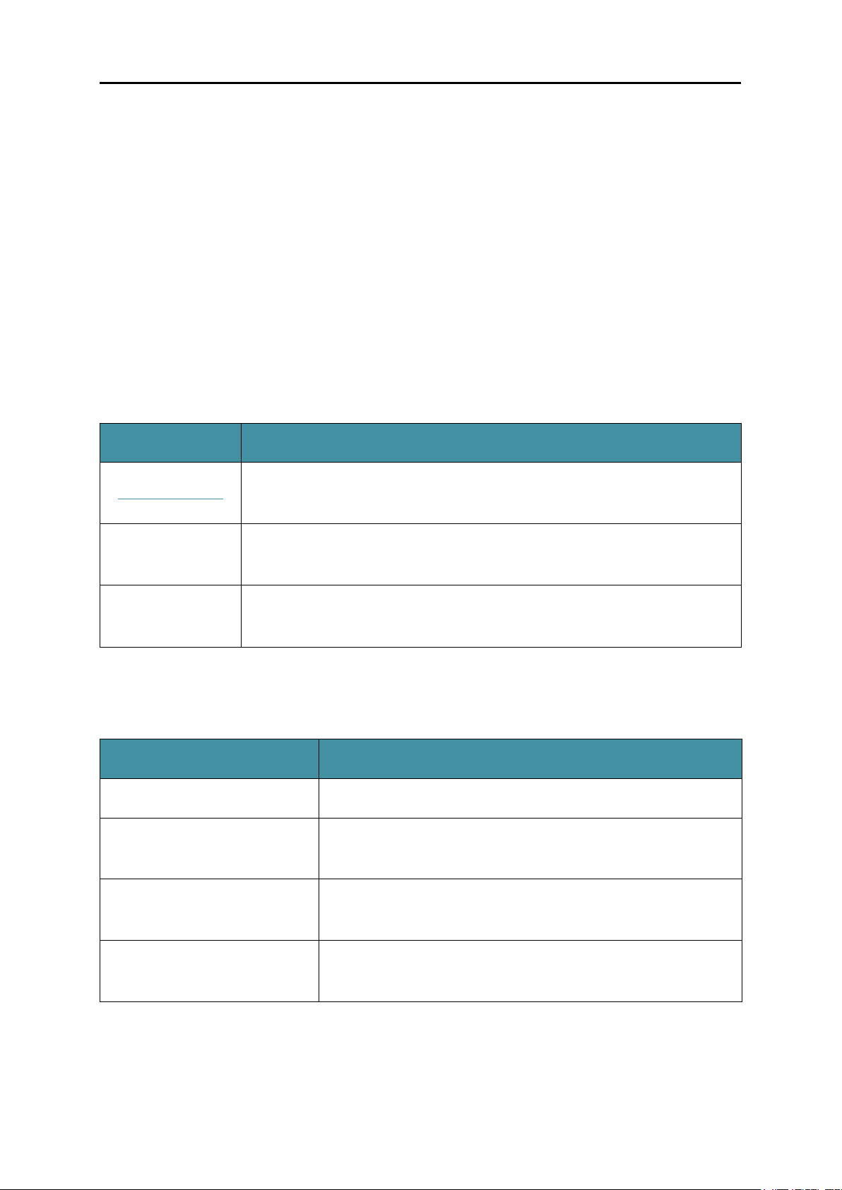
1.1 Conventions
In this Guide, the following conventions are used:
Convention Description
Teal Underlined
Teal
Note
Hyperlinks are teal underlined. You can click to redirect to a website or a
specific section.
including the menus, items, buttons, etc.
Ignoring this type of note might result in a malfunction or damage to the
device.
1.2 Overview of This Guide
Chapter 2 Get to Know Your
Introduces the features, application and appearance of the
Chapter 3 Set Up Your
Chapter 4 Configure Your
Introduces how to configure the camera using the built-in
1
Page 4

NC450
1.3 More Info
The latest software, management app and utility can be found at Download Center at
http://www.tp-link.com/support
The Quick Installation Guide can be found where you find this guide or inside the product
package.
Specifications can be found on the product page at http://www.tp-link.com
A Technical Support Forum is provided for you to discuss our products at
http://forum.tp-link.com
Our Technical Support contact information can be found at the Contact Technical Support
page at http://www.tp-link.com/support
.
.
.
.
2
Page 5

NC450
Chapter 2 Get to Know Your Camera
2.1 Product Overview
TP-Link NC450 HD Pan/Tilt Wi-Fi Camera is a cloud-based Wi-Fi video monitoring device with
live streaming and remote viewing, which makes it easy to stay connected with what you care
most.
Easy to install with tpCamera app
Remote monitoring via TP-Link Cloud website or tpCamera app
Get notifications when motion or sound is detected, and view alerts history
View clearer images with HD resolution
View clearly in the dark with night vision
Stay in touch with 2-way audio
Save the image and video in the Micro SD card
Patrol a large area with pan and tilt
2.2 Panel Appearance
2.2.1 Front Panel
Front Panel
3
Page 6
NC450
System LED:
Status
Indication
Flashing Red
The camera is starting up.
network.
The camera is in firmware upgrade procedure.
The camera is connecting to a network.
The camera is connected to a network.
The camera is transferring data.
Solid Red
Flashing Green
Solid Green
Microphone: The camera has a built-in internal microphone. This microphone is hidden in
the pinhole located on the front panel.
The camera has started up, but not connected to any
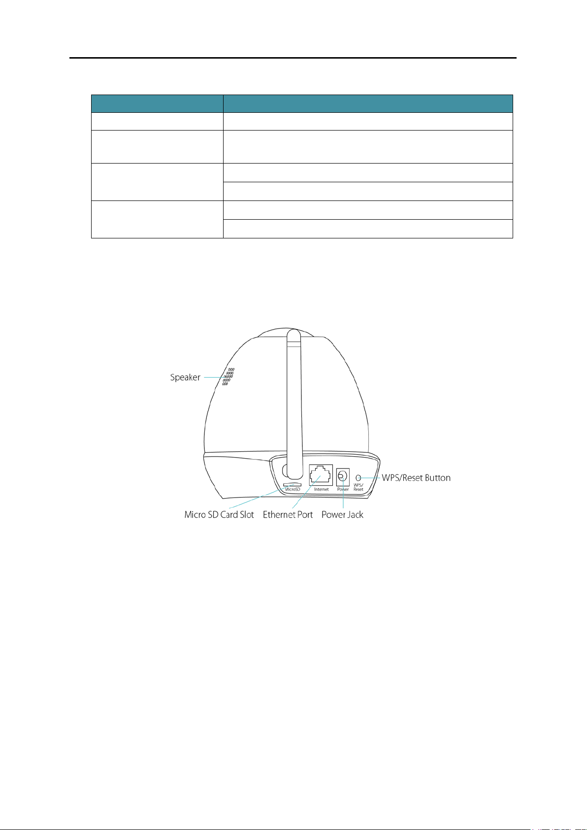
2.2.2 Rear Panel
Rear Panel
Speaker: For audio output.
Micro SD Card Slot: For holding the micro SD card.
Internet Port: For connecting the camera to your router via an Ethernet cable.
Power Jack: For connecting the camera to a power socket via the provided power adapter.
WPS/Reset Button: The switch for the WPS and Reset function. To use the WPS function,
press it for about 2 seconds. To use the Reset function, press and hold for more than 5
seconds.
• Used as the WPS button:
If your wireless router supports WPS (Wi-Fi Protected Setup), you can connect the
camera to your Wi-Fi network using WPS. Press the WPS or QSS button on your
4
Page 7

NC450
router. Within 2 minutes, press the WPS/Reset button on the camera for about 2
Status
Indication
The camera starts booting up.
The camera is connecting to a network by WPS function.
The camera has boot up.
The camera failed to be added to a network by WPS function.
function. This process will last in the first two minutes.
seconds, then the LED above this button will start flashing quickly. When this LED
becomes solid on, the WPS is successful.
• Used as the Reset button:
With the camera powered on, press and hold the WPS/Reset button (for more than 5
seconds) until the System LED turns off. Then release the button and wait the camera
to reset to its factory default settings.
WPS LED:
Flashing Green
Off
Solid Green
The camera
has been successfully added to a network by WPS
5
Page 8
NC450
Chapter 3 Set Up Your Camera
3.1 Set up the Camera with the tpCamera App
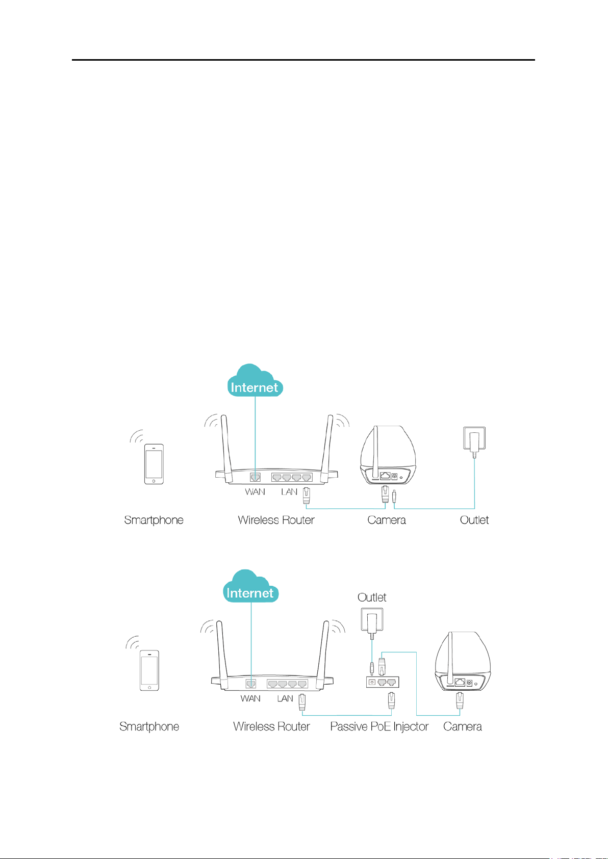
Step 1. Connect the camera to the network your smartphone is on.
1) Power on the camera using the provided power adapter as shown.
2) Connect a smartphone to the router as shown.
3) Connect the camera to the router via wired or wireless connection, and then wait till the
camera’s system LED become solid green.
Wired: Connect the camera to the router’s LAN port via an Ethernet cable or the provided
passive PoE injector.
Via an Ethernet cable
Via the provided passive PoE injector
6
Page 9
NC450
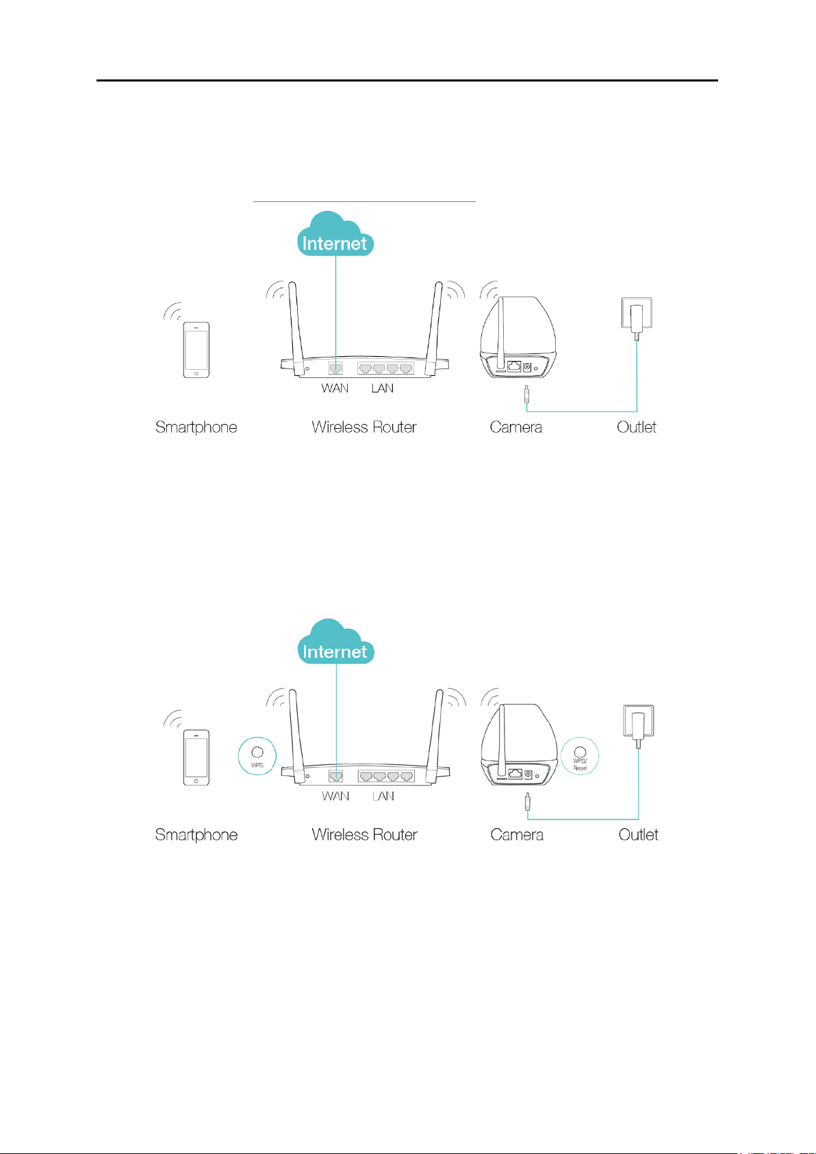
Wireless:
Via web management page
You can set the wireless connection using the basic settings on the web management
page. (Refer to 4.3.3 Basic > Wireless Connection
).
Via WPS/QSS button
If your wireless router supports WPS, you can connect the camera to your Wi-Fi
network using WPS. Press the WPS or QSS button on your router. Within 2 minutes,
press the WPS/Reset button on the back of the camera for about 2 seconds, then the
LED above this button will start flashing quickly. When this LED becomes solid on, the
WPS is successful and the camera is connected to the router wirelessly.
Step 2. Download and install the tpCamera app.
You can download the free tpCamera app from the App Store or Google play. You can also
scan the QR code below to download the tpCamera app.
7
Page 10

NC450
Step 3. Add the camera to your TP-Link ID.
Launch the tpCamera app, log in with your TP-Link ID or create one if you do not have a TP-Link
ID. Then follow the app instructions to add your new camera to your TP-Link ID.
When you reach the My Cam screen, you have successfully added your camera and can start
to use your camera.
Note:
You can enable Email and App notification in the app, which will inform you immediately of any
detected movement or sound by sending the snapshots. The time interval between each Email
notification alert is 10 minutes while the time interval for App notification is 3 minutes.
3.2 Position Your Camera
Before positioning your camera, please keep these safety guidelines in mind:
Keep your camera out of reach of children and pets.
Use your camera only indoors, and keep it out of direct sunlight. Make sure its operating
temperature is in the range of 0-40°C (32-104°F).
Pick a location which is close enough to a wall outlet.
Use only the power adapter that comes with this camera in the package.
You can place your camera to your desired location. Just unplug and replug it without having to
go through the app’s setup again. Place the camera within the coverage of your wireless
network. You can place the camera in various ways:
Place it on a flat surface.
Mount it on the wall or ceiling with the provided screws and base.
Detailed instructions on mounting your camera to a wall or ceiling are shown as follows.
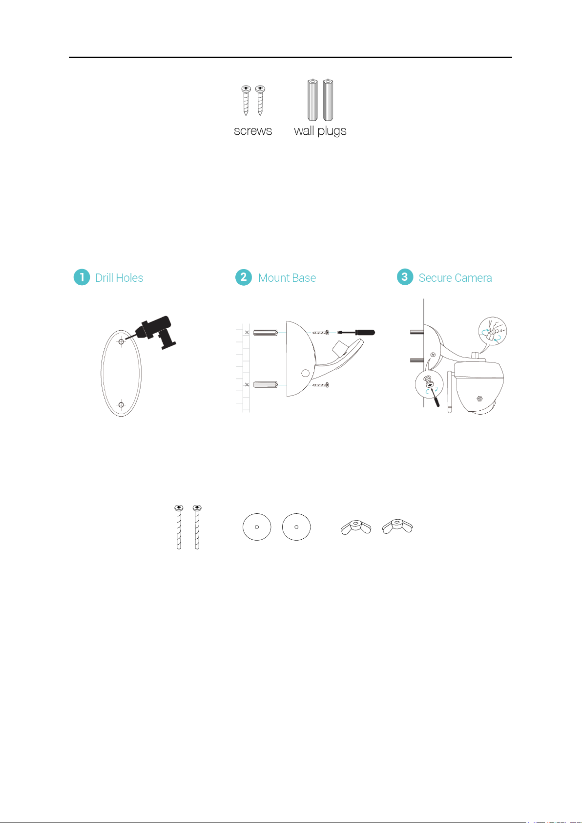
Wall Mounting
Get the provided accessories for camera’s wall mounting ready, and follow the instructions
below to mount the camera. After relocating your camera, remember to power on it.
8
Page 11
NC450
screws
wing nuts washers
A) Place the paper drill guide where you want the camera. Check the alignment using a level.
B) Using a 0.24 inch (6mm) drill bit, drill holes through the two circles on the guide. Remove the
paper.
C) Insert the two anchors into the holes and place the camera mount over the anchor.
D) Attach the camera and use the screws to secure it.
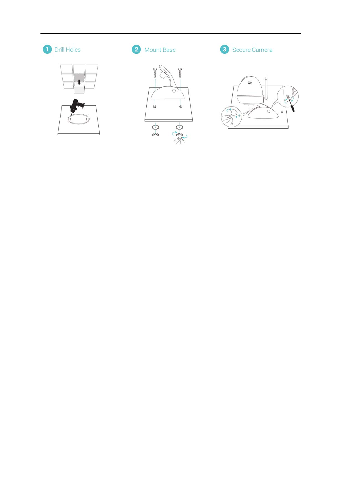
Ceiling Mounting
Get the provided accessories for camera’s wall mounting ready, and follow the instructions below
to mount the camera. After relocating your camera, remember to power on it.
A) Place the paper drill guide where you want the camera*.
*Camera placement can affect viewing angle. For best results, place the camera near a wall or
corner.
B) Using a 0.24 inch (6mm) drill bit, drill holes through the two circles on the guide. Remove the
paper.
C) Attach the camera mount using the screws, washers, and wingnuts.
D) Attach the camera and use the screws to secure it.
9
Page 12
NC450
When you finish positioning your camera, use the tpCamera app to check that your camera can
see what you want to keep an eye on. Adjust its position if needed.
10
Page 13
NC450
Chapter 4 Configure Your Camera
This chapter shows how to use the camera’s web management page to configure the camera
locally. In addition to the web management page, you can use the tpCamera app and TP-Link
Cloud (http://www.tplinkcloud.com
4.1 Log in to Your Camera
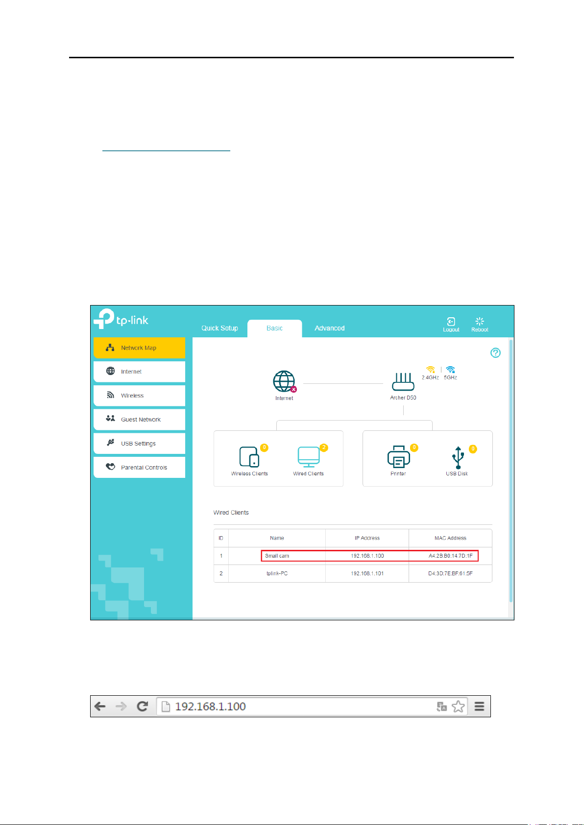
1. Connect a computer to the router that your camera is connected to. You can connect the
computer to the router using an Ethernet cable or via the wireless connection.
2. Find the management IP address of the camera from the web management page of the
connected router. Here we use the web management page of TP-Link router for
demonstration.
) to view and manage your camera remotely.
3. On a computer that connects to the same router as the camera does, open a web browser,
type in the camera’s IP address in the address field, and press Enter. Here we use
http://192.168.1.100 for demonstration.
11
Page 14
NC450
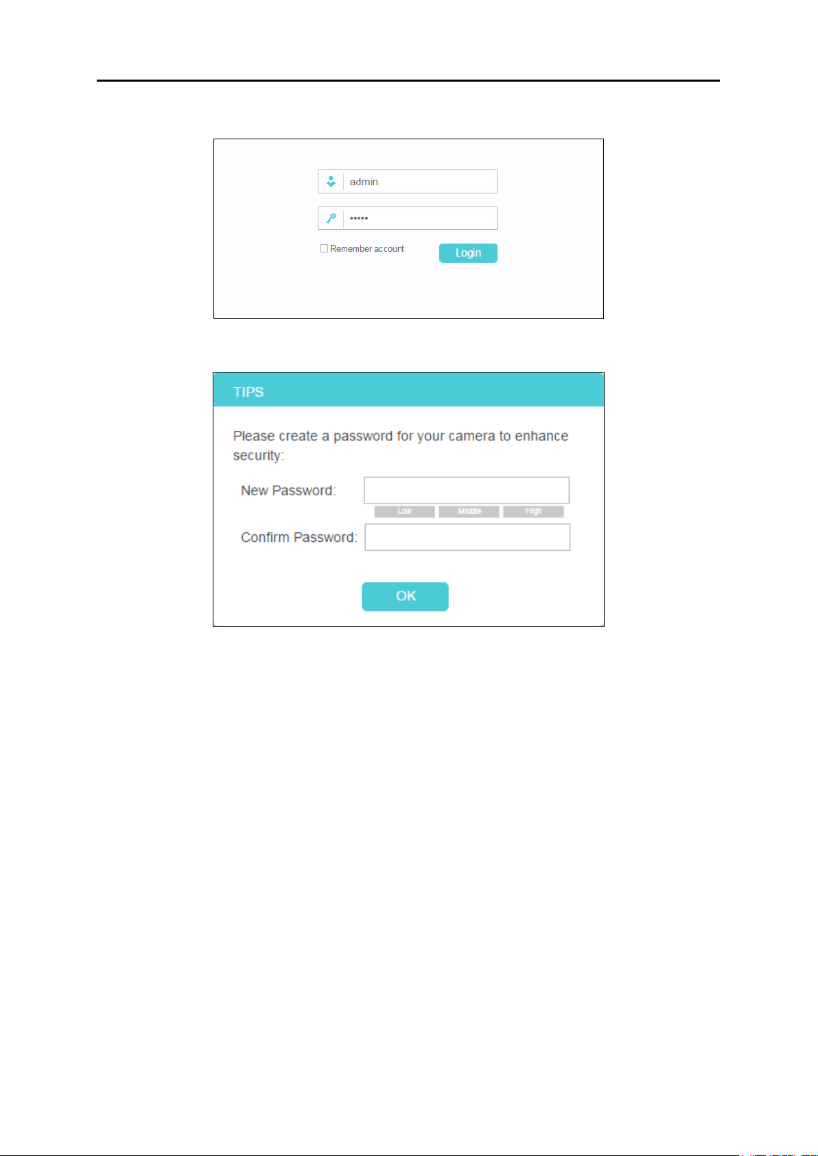
4. Enter the default username and password (admin/admin). Click Login.
5. Create a new password for your camera to enhance security. Click OK.
Note:
For the administrator, the default password is admin. For subsequent logins, use your
password you have created.
If you log in to the camera as an administrator, you can perform all the settings provided by the
camera.
If you log in to the camera as a common user, you can only view the Live View. After logging as
administrator, you can add up to five user accounts in the Account menu (Go to System >
Account).
12
Page 15
NC450
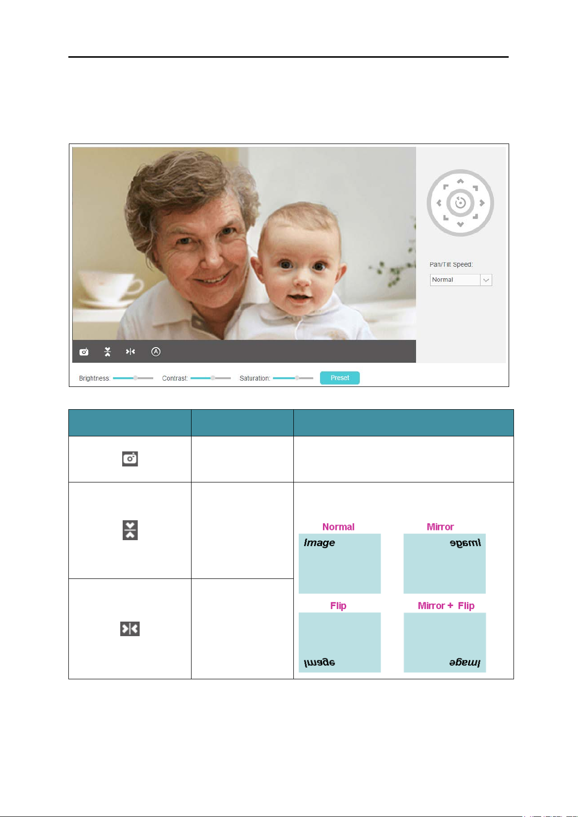
Click to capture a
the camera.
If the camera is installed upside down, Flip
4.2 Live View
The Live View screen shows you the live video feed from your camera. On this screen, you can
capture a picture.
Symbols Meaning Note
still image shot by
Click to vertically
flip the current
image.
Click to horizontally
flip the current
image.
The image file will be automatically saved to
your computer.
Image and Mirror should both be checked.
13
Page 16
NC450
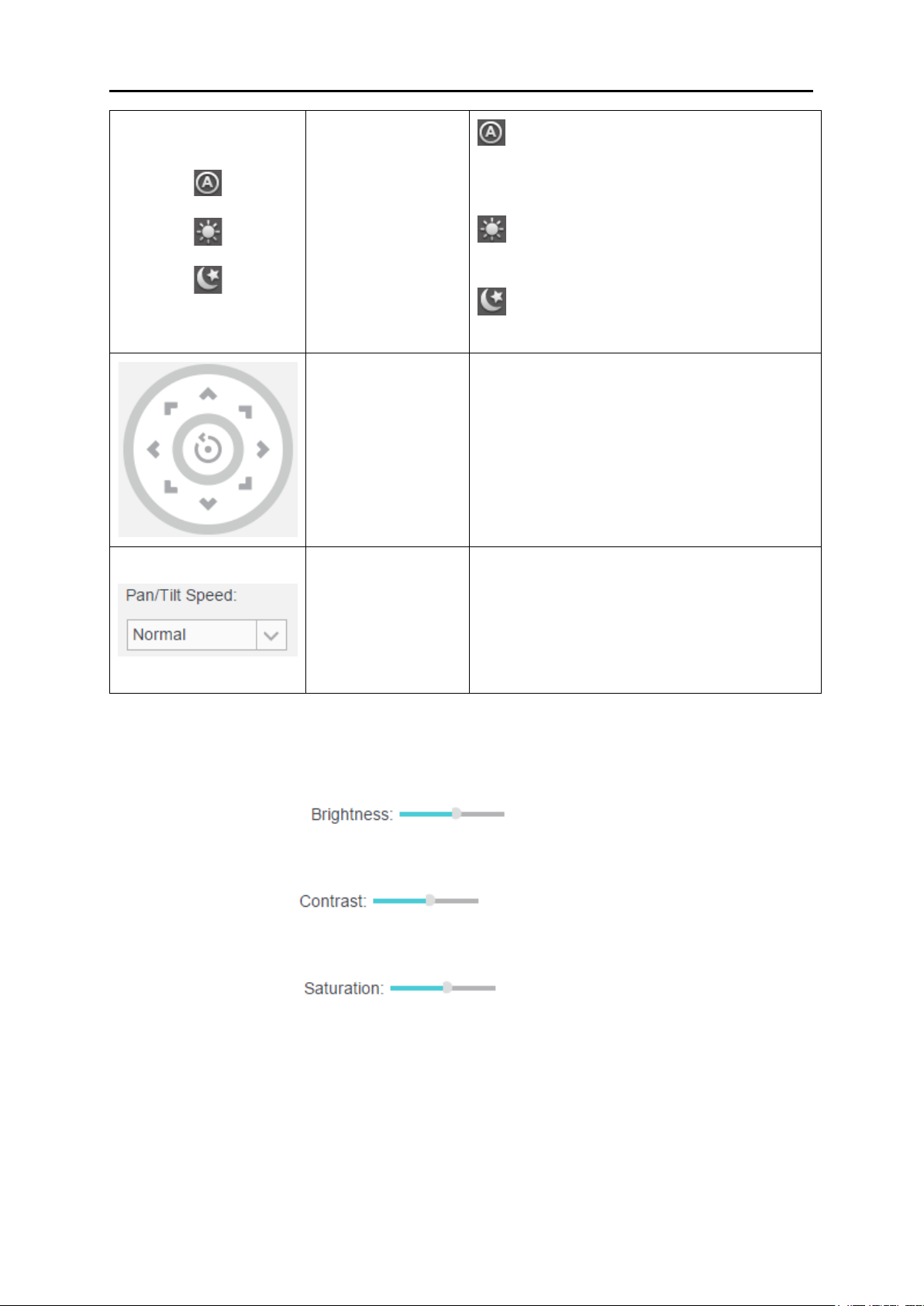
: This mode will automatically
in the Night mode.
pan and tilt
wheel to return the camera to its initial
Set the speed of
pan/tilt wheel.
Auto
switch between Day and Night modes based
Click to select the
Auto/Day/Night
mode.
Click to set the
camera’s position.
on the amount of available lighting.
Day: This sets the camera to always be
in the Day mode.
Night: This sets the camera to always be
Click on the directional arrows on the pan/tilt
wheel to manually control the
functions of the camera. At any time, you can
click the Return button in the center of the
position.
the camera’s
movement for each
press of a pan or tilt
arrow on the
Note:
Use the camera’s pan and tilt controls via the web management page or tpCamera app instead of
rotating the camera forcibly, which may cause damage to the camera.
Brightness: Drag the
Contrast: Drag the
Saturation: Drag the
camera. Large value will brighten the current displayed screen.
camera. Large value will contrast the current displayed screen heavily.
camera. Large value will saturate the current displayed screen to be more colorful.
Select the pan/tilt speed from the drop-down
list: Fast, Normal, Slow.
slider to adjust the brightness level of
slider to adjust the contrast level of the
slider to adjust the saturation level of the
Preset: Click the Preset button to restore to factory image settings.
14
Page 17

NC450
4.3 Basic
Click the Basic menu to display the submenus including Status, Network, Wireless Connection,
Cloud Setting, and LED.
4.3.1 Basic > Status
The Status page displays the current configuration information of the camera. All the
information is read-only.
15
Page 18

NC450
16
Page 19

NC450
4.3.2 Basic > Network
On this page, you can configure your camera’s IP address which is used to access and
configure the camera.
Dynamic IP: Select this option when a DHCP server is installed on the network to issue IP
address assignment. With this setting, the IP address of the camera is assigned
automatically.
Static IP: Select this option when a static or fixed IP address is obtained for the camera. A
static IP address will ease your access to the camera in the future. Add your camera’s
static IP information to your router to avoid IP conflicts.
• MAC Address: Displays the Ethernet MAC address of the camera. The MAC address is
read-only.
• IP Address: Enter a fixed IP address for the camera in dotted-decimal notation.
• Subnet Mask: Enter the subnet mask in dotted-decimal notation. The default value is
“0.0.0.0.”
• Default Gateway: Enter the default gateway in dotted-decimal notation.
17
Page 20

NC450
• Primary DNS Server: Enter a DNS address in dotted-decimal notation.
• Secondary DNS Server: Enter a DNS address in dotted-decimal notation.
Click Save to save and enable the settings.
4.3.3 Basic > Wireless Connection
The camera’s wireless function is enabled by default. This function helps to connect your
camera to a wireless network wirelessly. If you don’t want to use this function, just select the
Disable option.
Scan: Click to scan the available wireless network. You will get or refresh the Wireless
Network List as shown below.
18
Page 21

NC450
Wireless Network Name: Displays the wireless network’s name. Make sure the camera and
your PC connect to the same wireless network; otherwise your PC can't access the
camera.
Signal: Displays the strength of the wireless signal.
Security: Displays the wireless network’s security mode.
MAC Address: Displays the MAC address of the router.
To connect your camera to a wireless network, follow the steps below:
1. Click Scan to get and refresh the Wireless Network List.
2. Select a wireless network from the wireless network list.
3. If the wireless network’s security mode is None, simply click Connect. If the security mode
requires a password, enter the wireless network’s password and then click Connect. You
can select show password to display what you’ve entered.
19
Page 22

NC450
4. A pop-up screen will prompt you for the wireless network modification. Click Change, and
then click OK on the next pop-up screen. The camera will connect to the wireless network
that you have selected.
5. To log in to the web management page of the camera, you need to connect your computer
to the router that your camera is connected to. Refer to 4.1 Log in to Your Camera to find
the IP address of your camera and log in to the camera again.
4.3.4 Basic > Cloud Setting
A Cloud Camera can be viewed anytime and anywhere over the internet with TP-Link Cloud
service. On this page, you can add the camera to your TP-Link ID.
Note:
1. You can register a TP-Link ID in the tpCamera app only. If you do not get the tpCamera app,
please refer to the Step 2 Download and install the tpCamera app in
with the tpCamera App to register a TP-Link ID.
20
3.1 Set up the Camera
Page 23

NC450
2. To add a camera to your TP-Link ID, make sure that the camera is connected to the
internet.
Add Your Camera to TP-Link ID
If you already have a TP-Link ID, to add your camera to your account, just enter the TP-Link ID
and password, and then click Register.
Account: Enter your TP-Link ID. Either E-mail address or username is allowed.
Password: Enter your TP-Link ID’s password.
Camera Name: The default value is the camera model. You can change it to an
easy-to-remember one. Camera name can contain up to 31 characters. It cannot contain
the following characters: \ / : = & ‘ “ < > { }.
After your camera is registered successfully, you can go to http://www.tplinkcloud.com
it.
to view
4.3.5 Basic > LED
The camera’s LED is on by default. If you want to turn it off, select Off and click Save.
21
Page 24

NC450
4.4 Advanced
Click the Advanced menu to display the submenus including Status, Network, Wireless
Connection, Cloud Setting, Video, Sound Detection, Motion Detection, SD Card, Notification
Delivery and LED.
4.4.1 Advanced > Status
Refer to 4.3.1 Basic > Status.
4.4.2 Advanced > Network
On this page, you can configure the network settings of the camera.
22
Page 25

NC450
IP Address
On this section, you can configure your camera’s IP address which is used to access and
configure the camera.
Dynamic IP: Select this option when a DHCP server is installed on the network to issue IP
address assignment. With this setting, the IP address of the camera is assigned
automatically.
• Fallback IP: If the camera cannot get a dynamic IP address from a DHCP server within
limited tries, the camera will assign a default IP address, 192.168.0.10, by itself as the
Fallback IP address.
Static IP: Select this option when a static or fixed IP address is obtained for the camera. A
static IP address will ease your access to the camera in the future. Add your camera’s
static IP information to your router to avoid IP conflicts.
23
Page 26

NC450
• MAC Address: Displays the Ethernet MAC address of the camera. The MAC address is
read-only.
• IP Address: Enter a fixed IP address for the camera in dotted-decimal notation.
• Subnet Mask: Enter the subnet mask in dotted-decimal notation. The default value is
“0.0.0.0”.
• Default Gateway: Enter the default gateway in dotted-decimal notation.
• Primary DNS Server: Enter a DNS address in dotted-decimal notation.
• Secondary DNS Server: Enter a DNS address in dotted-decimal notation.
• Fallback IP: If the camera cannot get a valid static IP address, the camera will assign a
default IP address, 192.168.0.10, by itself as the Fallback IP address.
HTTP (Hypertext Transfer Protocol)
This feature allows you to access and manage your camera via its IP address. Web browser
access normally uses the standard HTTP service port 80. The camera uses HTTP port 80 by
default. For greater security, you can change the port to a custom one.
When HTTP port is set to 80, you can access the camera by typing its IP address (for example,
http://192.168.1.100) on a web browser. When HTTP port is set to another value (for example,
2000), you need to enter http://192.168.1.100:2000 instead.
24
Page 27

NC450
HTTP Port: The default value is 80. If you want to use a port number other than 80, enter a
port number between 1 and 65535.
Bonjour
Bonjour, also known as zero-configuration networking, enables automatic discovery of
computers, devices, and services on IP networks. Bonjour uses industry standard IP protocols
to allow devices to automatically discover each other without the need to enter IP addresses or
configure DNS servers.
Bonjour: To enable or disable the Bonjour service.
Bonjour Name: Displays the Bonjour name. By default, it is a combination of device name
and the last six characters of the camera’s MAC address.
Click Save to save and enable the settings.
25
Page 28

NC450
4.4.3 Advanced > Wireless Connection
You can set the wireless connection manually besides the basic settings for wireless
connection (Refer to 4.3.3 Basic > Wireless Connection
For example, a hidden wireless network does not broadcast its SSID, and you cannot find it
from the Wireless Network List. If you want to connect the camera to a hidden wireless network,
you need to make it manually. Click the Manually button. Then enter the wireless network name,
select the security type and encryption type of the wireless network, enter the password if
needed, and click Connect.
26
).
Page 29

NC450
4.4.4 Advanced > Cloud Setting
Refer to 4.3.4 Basic > Cloud Setting.
4.4.5 Advanced > Video
On this page, you can configure the video settings for your camera.
27
Page 30

NC450
Coding Format: Displays the video coding format of the camera.
Resolution: Displays the video resolution of the camera. Higher resolution offers better
quality, but will require more bandwidth to stream.
Frame Rate: Select the frame rate to use for the video stream from the drop-down list.
Higher settings offer smoother video streams, but will require more bandwidth.
Mode: Displays the bit rate mode of the camera. This camera uses the VBR (variable bit
rate) mode. In this mode, the bit rate varies to keep consistent video quality. It allows a
higher bit rate (and therefore requires more bandwidth) to be allocated to dynamic scenes
while less bit rate to be allocated to static scenes.
Image Quality: Select the image quality from the drop-down list: High and Low. High
settings offer better quality, but it may require more bandwidth to stream.
Backlight Compensation: If enabled, this feature will compensate for bright backgrounds
so foreground objects aren't silhouetted.
28
Page 31

NC450
Enabled
Disabled
Enabled
Disabled
Light Frequency: Select the frequency used by your lighting and power to help reduce
image flicker. The default setting is Auto, which is recommended.
Time Stamp&On-Screen Display (OSD): If enabled, the current time of your camera, which
can be set on the System > Date/Time page, will be displayed on the Live View screen.
Meanwhile, you can set the OSD text to be displayed with the time stamp. We use NC450
as the OSD text for demonstration here.
Click Save to save and enable the settings.
4.4.6 Advanced > Sound Detection
Sound detection allows your camera to detect a loud sound, which can be used to trigger
snapshots. Refer to 4.4.9 Advanced > Notification Delivery
29
for more details.
Page 32

NC450
Sound Detection: To enable or disable the sound detection function.
Sensitivity: Specify the level of difference between current sound and the threshold you
set. Select one of the three levels of sensitivity from the drop-down list: High, Medium, and
Low.
Threshold: Select the threshold of sound level. You can also drag the arrow in the diagram
to set the threshold. Snapshots will be triggered and sent to FTP server when current
sound exceeds the threshold. And notification messages will be sent to the tpCamera app
in your smartphone.
Click Save to save and enable the settings.
4.4.7 Advanced > Motion Detection
Motion detection allows you to specify areas and sensitivity of your camera’s video to monitor
for motion, which can be used to trigger snapshots. Refer to
Delivery for more details.
4.4.9 Advanced > Notification
30
Page 33

NC450
Motion Detection: To enable or disable the motion detection function. The area with blue
mask indicates that it is the area with motion detection on. All areas are selected by default.
You can drag your mouse to draw specific areas that you want to monitor.
Sensitivity: Select one of the three levels of sensitivity from the drop-down list: High,
Medium, and Low. Snapshots will be triggered and sent to FTP when the motion meets the
level of sensitivity. And notification messages will be sent to the tpCamera app in your
smartphone.
Click Save to save and enable the settings.
4.4.8 Advanced > SD Card
SD Card function allows you to save snapshots and videos in your SD card. The SD card is not
provided, and you need to insert a micro SD card into the SD card slot on the back of the
camera.
31
Page 34

NC450
After inserting a micro SD card, go to Advanced > Sound Detection or Advanced > Motion
Detection to set the detections according to your needs. Then when an event occurs, the
corresponding snapshot and video will be saved in the micro SD card automatically.
Note:
If the micro SD card capacity is insufficient, it will overwrite the oldest data.
Back: Click to go back to the previous path of the folder.
Type: Displays the type of the file or folder, such as the photo, video, and file.
Name: Displays the name of the file or folder.
Size: Displays the size of the file.
Total Items: Displays the number of the files in the folder.
Date: Displays the recording time of the file or folder.
The micro SD card capacity is displayed at the bottom of the table.
Note:
The Wi-Fi camera supports 24-hour recording. If you enable the 24-hour Recording function,
remember to save your previous recordings in your SD card to avoid them being overwritten.
If the 24-hour Recording function is disabled, the SD card recording triggered by motion
detection or sound detection will last from 15s to 60s (depending on how long the motion or
sound lasts). If the event continues beyond 60s, the camera will start a new recording.
32
Page 35

NC450
4.4.9 Advanced > Notification Delivery
Notification Delivery settings are available only after the motion detection or sound detection
function is enabled. It is used to inform you immediately by sending the snapshots triggered by
a detected motion or sound to the specified FTP server.
Select FTP, and you can configure your camera to send snapshots to a specified FTP server on
the following screen:
FTP Server/Port: Enter the IP or the domain (IP/domain without prefix ftp://) and the port of
the FTP server that you will be connecting to. The port is 21 by default.
Note:
The FTP server you set and the camera should be in the same LAN.
Username: Enter the username that is used to log in to your FTP server.
Password: Enter the password that is used to log in to your FTP server.
Path: Enter the path to the destination on the FTP server.
33
Page 36

NC450
Passive Mode: Enabling passive mode may help you reach your FTP server if your camera
is behind a router protected by a firewall.
To set up a FTP to receive notification, follow the steps below:
1. Enter an IP address or domain of your FTP server, e.g. 192.168.1.168
2. Remain the FTP port number as the default value: 21.
3. Enter your username to log in to the FTP server, e.g. test.
4. Enter your password to log in to the FTP server.
5. Enter the path to the destination on the FTP server, e.g. /test
6. Enable Passive Mode.
7. Click Save to save and enable the settings.
Click Test, and a test JPEG snapshot will be sent to the specified FTP server to check whether
your settings are correct.
If the settings are tested correct, click OK.
If the settings are tested incorrect, check your network and FTP settings and try again later.
34
Page 37

NC450
4.4.10 Advanced > LED
Refer to 4.3.5 Basic > LED.
4.5 System
Click the System menu to display the submenus including Account, Date/Time, Management,
and System Log.
4.5.1 Account
On this page, you can change the administrator’s password and manage the user account(s)
that are allowed to access to your camera.
User Name: Displays the name of the user account.
User Group: Displays the group that the user account is in. Different user group has
different limits of authority.
• admin: This group has all authority of configuration. It can only have one account:
admin.
• user: This group can only view the Live View. It can have up to five accounts.
35
Page 38

NC450
Add a New User Account
You can create a new user account to provide viewing access for your camera’s video. User
accounts will only be able to access the Live View section of the web management page, but
cannot access any other parts or change any settings.
To add a new user account, follow the steps below:
1. Click Add, and you will see the following screen.
2. Enter a username for your new account.
3. Enter a password for your new account. The password should contain 5 to 20 characters.
4. Enter the password again to confirm it.
5. Click Save to save and enable the settings.
Change Password
You can change the password of all the accounts here.
Note:
The default account and password are both admin. Everyone who knows the camera’s IP
address can access the device with all configuration authority. It is necessary to change the
default password if the device is intended to be accessed only by administrator.
To change password, follow the steps below:
1. Select a user account in the list whose password you want to change
2. Click Change Password, and you will see the following screen.
36
Page 39

NC450
3. Enter the current password in the Old Password textbox.
4. Enter a new password.
5. Enter the new password again to confirm it.
6. Click Save to save and enable the settings.
Delete a User Account
You can delete a user account except admin here. Click a user entry in the list and click Delete.
4.5.2 Date/Time
On this page, you can configure the settings of the internal system clocks for your camera.
37
Page 40

NC450
Current Time: Displays the current date and time of the camera.
Time Zone: Select the time zone for the region where the camera is installed from the
drop-down list.
Synchronize With NTP Server: Select this option to specify the NTP server name to
synchronize the date and time of the camera with those of the time server, known as the
NTP (Network Time Protocol) server.
• NTP Service: You can either enter a domain name of the NTP server or select one
which will be filled in automatically from the drop-down list.
• Set NTP Server from Dynamic IP: You can use the NTP server applied in the DHCP
server on the network.
Set Date and Time Manually: Select this option to set the date and time of the camera
manually. If enabled, you will see the following screen:
38
Page 41

NC450
• Copy Your Computer’s Time Settings: Click this button to copy your computer’s
current time settings.
Click Save to save and enable the settings.
4.5.3 Management
On this page, you can reboot the camera, backup and restore the camera’s current settings,
reset factory settings, and update the camera’s software.
39
Page 42

NC450
Reboot: Click Reboot and then click Reboot on the pop-up screen to confirm. The reboot
will not change the camera’s setting. After rebooting, you need to log in to this page again.
Backup: Click Backup and follow the instructions on the browser to save the setting data
file to your specified location.
Browse: Click Browse to locate the saved backup file.
Restore: Click Restore, and then the camera will start rebooting. The settings will be
restored to the previous configuration.
Reset: Click Reset to restore the camera to its factory defaults. Don't turn off the camera
while resetting. After resetting, you need to add the camera to your TP-Link ID again, find
out the IP address of your camera (refer to 4.1 Log in to Your Camera
), and then use the
default username and password (admin/admin) to log in to this web management page.
Browse: Click Browse to locate the saved upgrade file.
Upgrade: Before update, download the latest firmware from the product page at
http://www.tp-link.com
, and then use decompression software to extract the file. Click
Browse and select the downloaded firmware upgrade file. Then click Upgrade to update
the camera’s software to the latest version. Wait for the upgrading process to complete,
and the camera will reboot automatically.
40
Page 43

NC450
Note:
The firmware upgrade procedure must not be interrupted, or the camera may be damaged.
When upgrading firmware, do not unplug the camera or your computer, or close the web
management page until the process is complete.
4.5.4 System Log
On this page, you can review any changes and events happened to your camera. The system
starts logging automatically after startup.
Time: Displays the time when the log event occurs. The log can get the correct time after
you configure on the Date/Time page. (Go to Advanced > Date/Time)
Module: Displays the module to which the log information belongs. You can specify the
module by selecting one from the Module drop-down list at the bottom.
Level: Displays the severity level of the log information. You can specify the level by
selecting one from the Level drop-down list at the bottom.
Content: Displays the details of the log information.
Refresh: Click Refresh to refresh the log information.
Save Log: You may be asked to use this function when contacting our technical support for
troubleshooting.
Clear: Click Clear to clear all the log information.
Log Control: You may be asked to use this function when contacting our technical support
for troubleshooting.
41
Page 44

COPYRIGHT & TRADEMARKS
Specifications are subject to change without notice. TP-Link is a registered trademark of
TP-Link Technologies Co., Ltd. Other brands and product names are trademarks or registered
trademarks of their respective holders.
No part of the specifications may be reproduced in any form or by any means or used to make
any derivative such as translation, transformation, or adaptation without permission from
TP-Link Technologies Co., Ltd. Copyright © 2017 TP-Link Technologies Co., Ltd. All rights
reserved.
http://www.tp-link.com
42
Page 45

FCC STATEMENT
This equipment has been tested and found to comply with the limits for a Class B digital device,
pursuant to part 15 of the FCC Rules. These limits are designed to pro-vide reasonable
protection against harmful interference in a residential installation. This equipment generates,
uses and can radiate radio frequency energy and, if not in-stalled and used in accordance with
the instructions, may cause harmful interference to radio communications. However, there is
no guarantee that interference will not occur in a particular installation. If this equipment does
cause harmful interference to radio or television reception, which can be determined by turning
the equipment off and on, the user is encouraged to try to correct the interference by one or
more of the following measures:
Reorient or relocate the receiving antenna.
Increase the separation between the equipment and receiver.
Connect the equipment into an outlet on a circuit different from that to which the receiver
is connected.
Consult the dealer or an experienced radio/ TV technician for help.
This device complies with part 15 of the FCC Rules. Operation is subject to the following two
conditions:
1) This device may not cause harmful interference.
2) This device must accept any interference received, including interference that may cause
undesired operation.
Any changes or modifications not expressly approved by the party responsible for compliance
could void the user’s authority to operate the equipment.
Note: The manufacturer is not responsible for any radio or TV interference caused by
unauthorized modifications to this equipment. Such modifications could void the user’s
authority to operate the equipment.
FCC RF Radiation Exposure Statement:
This equipment complies with FCC RF radiation exposure limits set forth for an uncontrolled
environment. This device and its antenna must not be co-located or operating in conjunction
with any other antenna or transmitter.
43
Page 46

“To comply with FCC RF exposure compliance requirements, this grant is applicable to only
Mobile Configurations. The antennas used for this transmitter must be installed to provide a
separation distance of at least 20 cm from all persons and must not be co-located or operating
in conjunction with any other antenna or transmitter.”
CE Mark Warning
This is a class B product. In a domestic environment, this product may cause radio interference,
in which case the user may be required to take adequate measures.
Adapter shall be installed near the equipment and shall be easily accessible.
Caution
Please make sure the temperature for adapter will be from 0 ˚C to 40 ˚C.
RF Exposure Information
This device meets the EU requirements (1999/5/EC Article 3.1a) on the limitation of exposure of
the general public to electromagnetic fields by way of health protection.
The device complies with RF specifications when the device used at 20 cm from your body.
Canadian Compliance Statement
This device complies with Industry Canada license-exempt RSSs. Operation is subject to the
following two conditions:
1) This device may not cause interference, and
2) This device must accept any interference, including interference that may cause undesired
operation of the device.
Le présent appareil est conforme aux CNR d’Industrie Canada applicables aux appareils radio
exempts de licence. L’exploitation est autorisée aux deux conditions suivantes:
1) l’appareil ne doit pas produire de brouillage;
2) l’utilisateur de l’appareil doit accepter tout brouillage radioélectrique subi, meme si le
brouillage est susceptible d’en compromettre le fonctionnement.
44
Page 47

This radio transmitter (IC: 8853A-NC450/ Model: NC450) has been approved by Industry
Canada to operate with the antenna types listed below with the maximum permissible gain
indicated. Antenna types not included in this list (Appendix A), having a gain greater than the
maximum gain indicated for that type, are strictly prohibited for use with this device.
Le présent émetteur radio (IC: 8853A-NC450/ Model: NC450) a été approuvé par Industrie
Canada pour fonctionner avec les types d'antenne énumérés ci-dessous et ayant un gain
admissible maximal. Les types d'antenne non inclus dans cette liste (Annexe A), et dont le gain
est supérieur au gain maximal indiqué, sont strictement interdits pour l'exploitation de
l'émetteur.
Radiation Exposure Statement:
This equipment complies with IC radiation exposure limits set forth for an uncontrolled
environment. This equipment should be installed and operated with minimum distance 20cm
between the radiator & your body.
Déclaration d'exposition aux radiations:
Cet équipement est conforme aux limites d'exposition aux rayonnements IC établies pour un
environnement non contrôlé. Cet équipement doit être installé et utilisé avec un minimum de
20 cm de distance entre la source de rayonnement et votre corps.
Industry Canada Statement
CAN ICES-3 (B)/NMB-3(B)
Korea Warning Statements:
당해 무선설비는 운용중 전파혼신 가능성이 있음.
NCC Notice
注意!
依據 低功率電波輻射性電機管理辦法
第十二條 經型式認證合格之低功率射頻電機,非經許可,公司、商號或使用者均不得擅自變更頻率、
加大功率或變更原設計之特性或功能。
第十四條 低功率射頻電機之使用不得影響飛航安全及干擾合法通行;經發現有干擾現象時,應立即
停用,並改善至無干擾時方得繼續使用。前項合法通信,指依電信規定作業之無線電信。低功率射
頻電機需忍受合法通信或工業、科學以及醫療用電波輻射性電機設備之干擾。
45
Page 48

BSMI Notice
安全諮詢及注意事項
請使用原裝電源供應器或只能按照本產品注明的電源類型使用本產品。
清潔本產品之前請先拔掉電源線。請勿使用液體、噴霧清潔劑或濕布進行清潔。
注意防潮,請勿將水或其他液體潑灑到本產品上。
插槽與開口供通風使用,以確保本產品的操作可靠並防止過熱,請勿堵塞或覆蓋開口。
請勿將本產品置放於靠近熱源的地方。除非有正常的通風,否則不可放在密閉位置中。
請不要私自打開機殼,不要嘗試自行維修本產品,請由授權的專業人士進行此項工作。
Продукт сертифіковано згідно с правилами системи УкрСЕПРО на відповідність вимогам
нормативних документів та вимогам, що передбачені чинними законодавчими актами
України.
Safety Information
When product has power button, the power button is one of the way to shut off the
product; when there is no power button, the only way to completely shut off power is to
disconnect the product or the power adapter from the power source.
Don’t disassemble the product, or make repairs yourself. You run the risk of electric shock
and voiding the limited warranty. If you need service, please contact us.
Avoid water and wet locations.
Adapter shall be installed near the equipment and shall be easily accessible.
The plug considered as disconnect device of adapter.
Use only power supplies which are provided by manufacturer and in the original
packing of this product. If you have any questions, please don't hesitate to contact us.
46
Page 49

Symbol
Explanation
Explanation of the symbols on the product label
DC voltage
Indoor use only
RECYCLING
This product bears the selective sorting symbol for Waste electrical and
electronic equipment (WEEE). This means that this product must be handled
pursuant to European directive 2012/19/EU in order to be recycled or
dismantled to minimize its impact on the environment.
User has the choice to give his product to a competent recycling organization or
to the retailer when he buys a new electrical or electronic equipment.
47
 Loading...