

Toyota RAV4 (RHD) - MMC Installation Instructions Manual

**
A2*R
(Production date 08/03)
Toyota Genuine Audio
INSTALLATION INSTRUCTIONS
FOR
TOYOTA MOTOR CORPORATIONManual Ref. n° A3RA2/W-2-0
RAV4 (RHD) - MMC

RAV4 (A2) TOYOTA GENUINE AUDIO
RAV4 (RHD) - 3
11-03
TABLE OF CONTENTS
1. Audio Application Chart ............................................................................................................................................. 4
2. System Layout ........................................................................................................................................................... 6
3. 1.4Din Audio Installation ............................................................................................................................................ 7
4. Wide 2Din Audio Installation ...................................................................................................................................... 10
5. Seat Mounted CD-Changer Installation (Passenger Seat) .......................................................................................... 12
6. Subwoofer Installation ............................................................................................................................................... 19
0.6 CD-Chan
g
er
(
oran
g
e
)
(
08601-00914
)
0.6 CD-Deck
(
oran
g
e
)
(
08601-00909
)
Seat mount CD-Chan
g
er TM0461
(
08601-00912
)
Navi
g
ation S
y
stem TNS300
(
08545-52800
)
1
Radio/Cassette
(
onl
y)
08600-00964
(
oran
g
e
)
Cover
p
late
(
55522-42010
)
2
Radio/Cassette + CD-Deck 08600-00964
(
oran
g
e
)
-
3
Radio/Cassette + CD-Chan
g
er 08600-00964
(
oran
g
e
)
-
08600-00964
(
oran
g
e
)
Cover
p
late
(
55522-42010
)
08600-00964
(
oran
g
e
)
(
1
)
F/K
(
08695-00803
)
+ Cover
p
late
(
55522-42010
)
4
Radio/CD
(
onl
y)
08600-00966
(
oran
g
e
)
Cover
p
late
(
55522-42010
)
5
Radio/CD + CD-Deck 08600-00966
(
oran
g
e
)
6
Radio/CD + CD-Chan
g
er 08600-00966
(
oran
g
e
)
-
08600-00966
(
oran
g
e
)
Cover
p
late
(
55522-42010
)
08600-00966
(
oran
g
e
)
(
1
)
F/K
(
08695-00803
)
+ Cover
p
late
(
55522-42010
)
7
(
Radio/Cassette/CD
)
+ CD-Chan
g
er MOP
(
1
)
Conversion Harness 08695-00370 + F/K
(
08695-00803
)
+ ADD-ON UNIT
(
S
)
HEAD UNITCOMBINATION REQUIRED ADDITIONAL PARTS
1.4 DIN Head-Unit Full Map Navigation
AUDIO & NAVIGATION APPLICATION CHART
TMME-CS group - November 17th, 2003
RAV4 MMC **A2*
(RHD)
p. 1/2
MOP: Factory installed option - (*): Outside temperature sensor PZ432-R0310-00 can be retro-fitted. - Subwoofer PZ08691-00834: On the floor under the passenger seat (if free)
F/K 08695-00803: Hanging seat mounting kit - (1): Hanging under the passenger seat - (2): On the floor under the passenger seat
0.6 CD-Chan
g
er
(
oran
g
e
)
(
08601-00914
)
0.6 CD-Deck
(
oran
g
e
)
(
08601-00909
)
Seat mount CD-Chan
g
er TM0461
(
08601-00912
)
Navi
g
ation S
y
stem TNS300
(
08545-52800
)
+ ADD-ON UNIT
(
S
)
HEAD UNITCOMBINATION REQUIRED ADDITIONAL PARTS
AUDIO & NAVIGATION APPLICATION CHART
TMME-CS group - November 17th, 2003
RAV4 MMC **A2*
(RHD)
8
Radio/Cassette
(
onl
y)
MOP-Unit
-
or 08600-00954(orange) (*)
-
9
Radio/Cassette + CD-Changer MOP-Unit
(1) F/K (08695-00803)
or 08600-00954 (orange) (*)
(1) F/K (08695-00803)
10
Radio/Cassette + Navi
g
ation
(
TBT
)
MOP-Unit
(
2
)
or 08600-00954
(
oran
g
e
)
(
*
)
(
2
)
11
Radio/Cassette + CD-Chan
g
er + Navi
g
ation
(
TBT
)
MOP-Unit
(
1
)
(
2
)
F/K
(
08695-00803
)
or 08600-00954
(
oran
g
e
)
(
*
)
(
1
)
(
2
)
F/K
(
08695-00803
)
12
Radio/CD
(
onl
y)
MOP-Unit
-
or 08600-00959
(
oran
g
e
)
(
*
)
-
13
Radio/CD + CD-Chan
g
er MOP-Unit
(
1
)
F/K
(
08695-00803
)
or 08600-00959
(
oran
g
e
)
(
*
)
(
1
)
F/K
(
08695-00803
)
14
Radio/CD + Navi
g
ation
(
TBT
)
MOP-Unit
(
2
)
or 08600-00959
(
oran
g
e
)
(
*
)
(
2
)
15
Radio/CD + CD-Chan
g
er + Navi
g
ation
(
TBT
)
MOP-Unit
(
1
)
(
2
)
F/K
(
08695-00803
)
or 08600-00959 (orange) (*)
(1) (2) F/K (08695-00803)
Wide 2-DIN Head-Unit
p. 2/2
MOP: Factory installed option - (*): Outside temperature sensor PZ432-R0310-00 can be retro-fitted. - Subwoofer PZ08691-00834: On the floor under the passenger seat (if free)
F/K 08695-00803: Hanging seat mounting kit - (1): Hanging under the passenger seat - (2): On the floor under the passenger seat
RAV4 (A2) TOYOTA GENUINE AUDIO
RAV4 (RHD) - 6
11-03
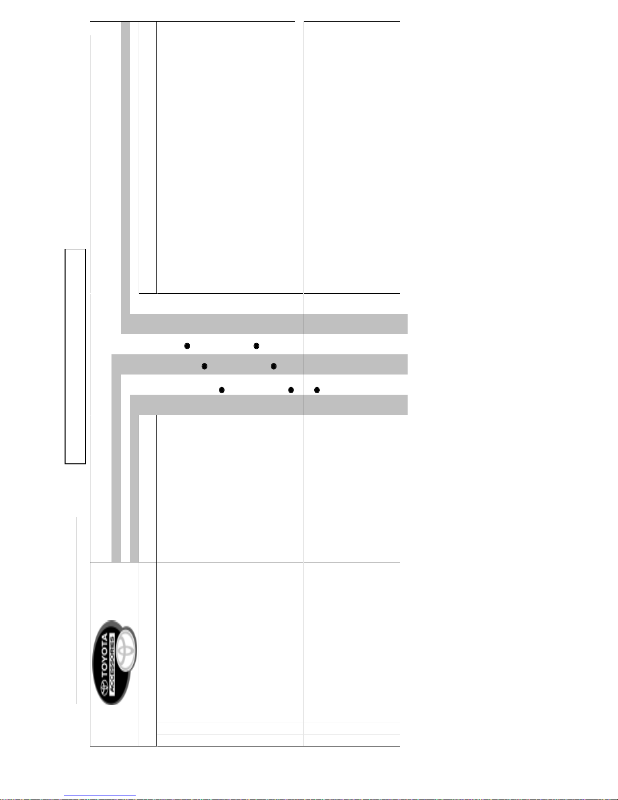
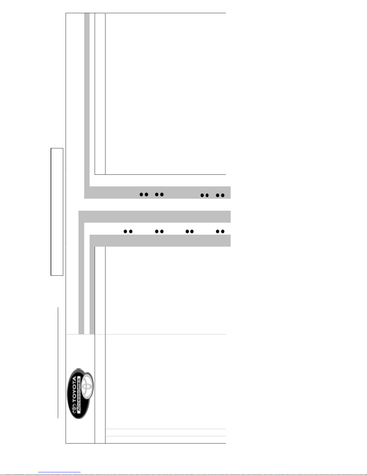
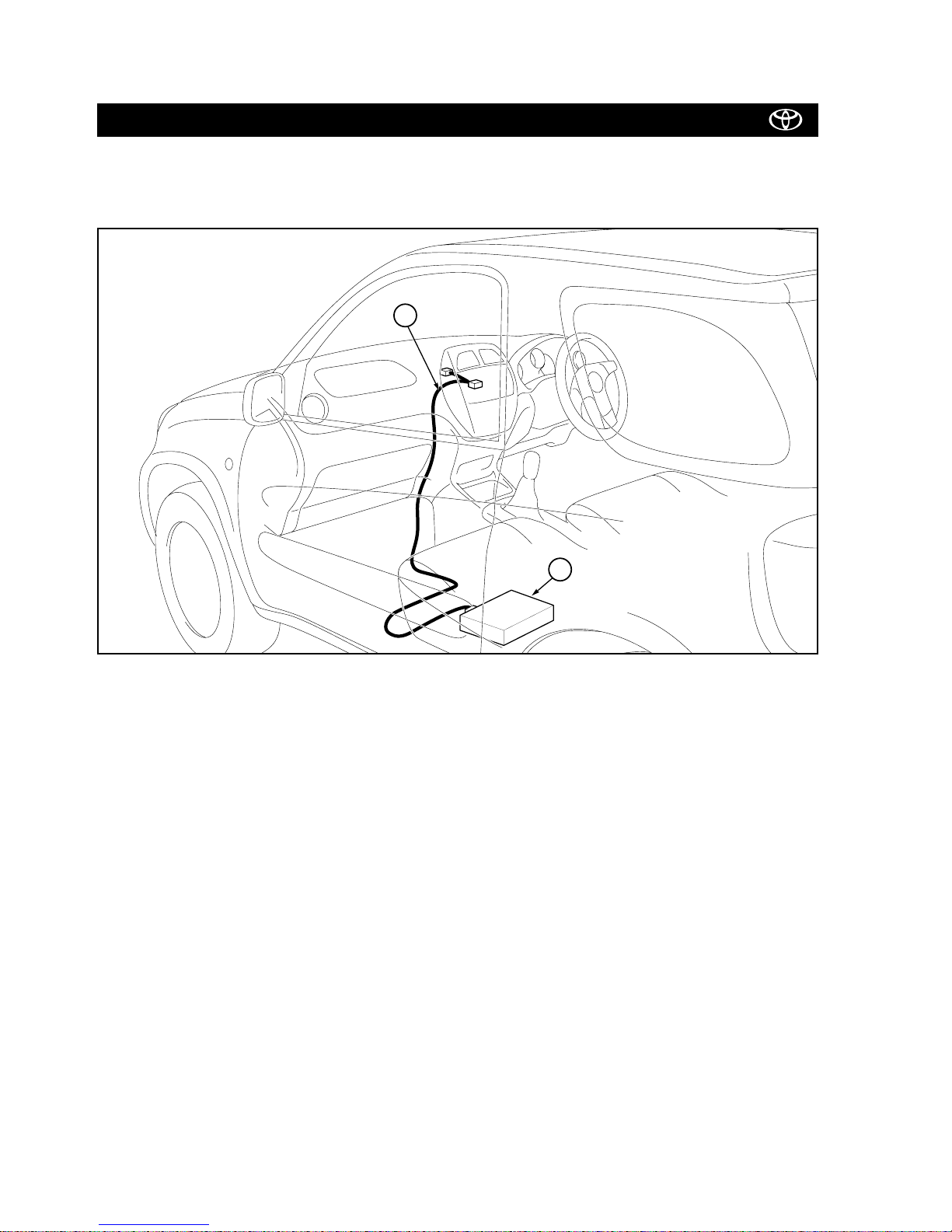
2. SYSTEM LAYOUT
2.1 CD-CHANGER INSTALLATION UNDER THE PASSENGER SEAT
NOTE:
To install the CD-changer in hanging position under the passenger seat, you will need the seat-mounted 6 CD-changer
TM0461 (08601-00912) and the seat-mounting kit F/K (08695-00803).
9
5
RAV4 (A2) TOYOTA GENUINE AUDIO
RAV4 (RHD) - 7
11-03
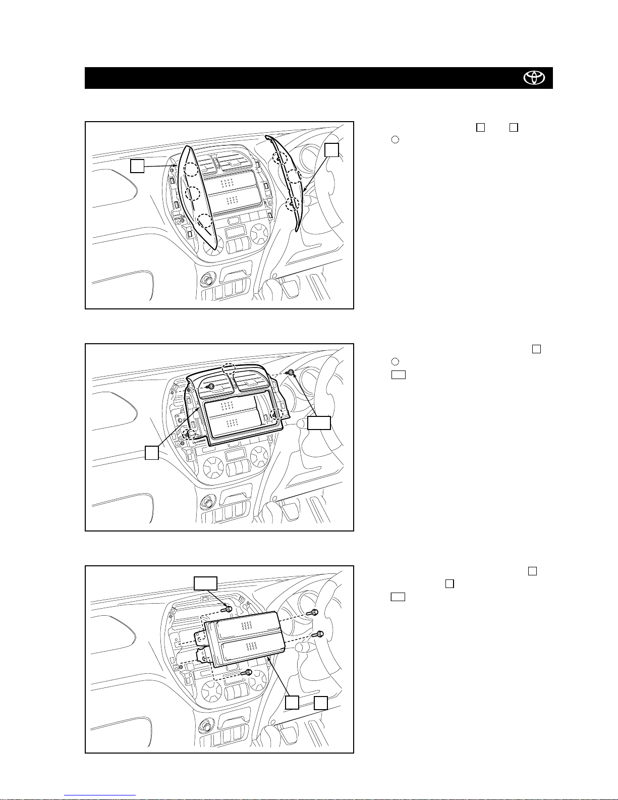
3. 1.4DIN AUDIO INSTALLATION
1. Remove the covers and .
: Clip (6x)
21
2. Remove the centre cluster panel .
: Clip (3x)
: Screw (2x)
100
3
Fig. 1
Fig. 2
2
1
3. Remove the accessory boxes or
cover plates .
: Screw (4x)
101
5
4
Fig. 3
4
5
101
or
3
100
RAV4 (A2) TOYOTA GENUINE AUDIO
RAV4 (RHD) - 8
11-03
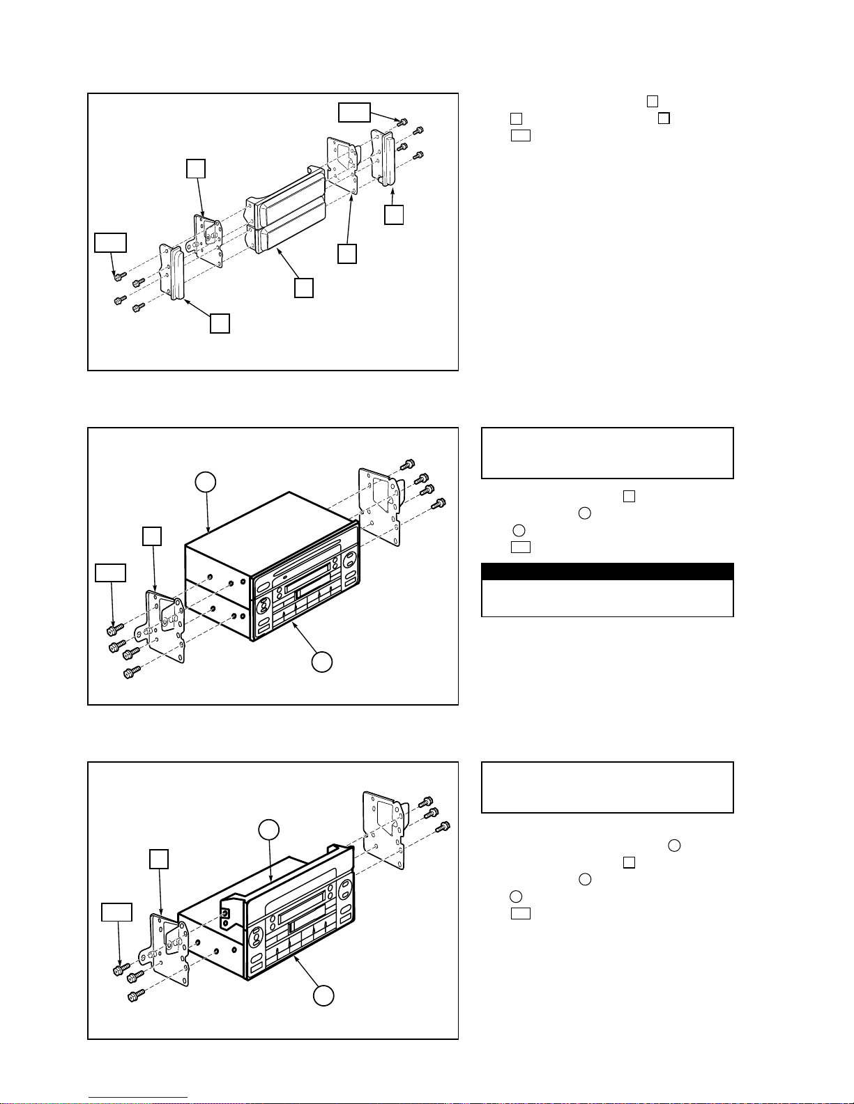
6.
a) Fit the 0.6-DIN cover plate .
b) Mount the brackets (2x) onto the 1.4
DIN combo and 0.6DIN cover plate
.
: Screw (6x)
102
3
1
6
3
Fig. 6
6
3
1
102
IN CASE OF 1.4DIN COMBO
+ 0.6DIN COVER PLATE
4. Remove the brackets and panels
from the cover plates .
: Screw (8x)
102
5
7
6
Fig. 4
(R)
(R)
(L)
(L)
5
7
6
6
7
102
102
5. Mount the brackets (2x) onto the 1.4
DIN combo and 0.6DIN add on unit
.
: Screw (8x)
102
2
1
6
Fig. 5
6
2
1
102
In case of 1.4DIN Combo
+ 0.6DIN Add on unit
For part number see audio application chart pages 4 to 5.
NOTE
 Loading...