


 Loading...
Last Modified: 3-27-2012 |
6.4 F |
From: 201203 |
Model Year: 2013 |
Model: FR-S |
Doc ID: RM0000010EX1UGX |
Title: FOREWORD / CAUTION / SECTION: FOREWORD: CAUTION (2013 FR-S)
CAUTION
This contents does not include all the necessary items about repair and service. This manual is made for the use of persons who have special techniques and certifications. If non-specialized or uncertified technicians perform repairs or service only using this manual or without proper equipment or tools, this may cause severe injury to you or other persons nearby and also cause damage to your customer's vehicle.
In order to prevent dangerous operation and damage to your customer's vehicle, be sure to follow the instructions shown below.
 This contents must be read thoroughly. It is especially important to have a good understanding of all the contents written in the PRECAUTION of "INTRODUCTION" section.
 The service method written in this manual is very effective to perform repair and service. When performing the operations following the procedures using this manual, be sure to use tools specified and recommended. If using non-specified or tools other than recommended tools and service methods, be sure to confirm the safety of the technicians and that there is no possibility of causing personal injury or damage to the customer's vehicle before starting the operation.
 If part replacement is necessary, the part must be replaced with the same part number or equivalent part. Do not replace it with an inferior quality part.
 It is important to note that this manual contains various "Cautions" and "Notices" that must be carefully observed in order to reduce the risk of personal injury during service or repair, or reduce the possibility that improper service or repair may damage the vehicle or render it unsafe. It is also important to understand that these "Cautions" and "Notices" are not exaggerations and are possible hazardous consequences that might result from failure to follow these instructions.
Last Modified: 3-27-2012 |
6.4 F |
From: 201203 |
Model Year: 2013 |
Model: FR-S |
Doc ID: RM0000010EW2RZX |
Title: FOREWORD / CAUTION / SECTION: FOREWORD: FOREWORD (2013 FR-S)
FOREWORD
This is Volume 1 of the 2013 SCION FR-S manual. There are three volumes to this manual. The sections included in each volume are indicated by black type in the Section Index. Use the Section Index of each volume to find the volume with the section you need.
Applicable models |
ZN6 series |
Please note that the publications below have also been prepared as relevant service manuals for the components and system in these vehicles.
|
MANUAL NAME |
|
PUB. NO. |
|
|
|
|
2013 |
SCION FR-S Electrical Wiring Diagram |
|
EM20S0U |
2013 |
SCION FR-S New Car Features |
|
NM20S0U |
All information in this manual is based on the latest product information at the time of publication. However, specifications and procedures are subject to change without notice. For the most current information available, refer to the Toyota Technical Information System (TIS) online at dealership locations or on the Internet at http://techinfo.toyota.com.
If you find any failures in this manual, you are kindly requested to inform us by using the report form on the next page.
Repair Manual Quality Report
Att.) Service Manager, Your Distributor
Last Modified: 3-27-2012 |
6.4 F |
From: 201203 |
Model Year: 2013 |
Model: FR-S |
Doc ID: RM000000UYV0BHX |
 Title: INTRODUCTION: HOW TO USE THIS MANUAL: GENERAL INFORMATION (2013 FR-S)
GENERAL INFORMATION
1.GENERAL DESCRIPTION
(a)This manual is written in accordance with SAE J2008.
(b)Repair operations can be separated mainly into the following 3 processes:
(1)Diagnosis
(2)Removing/Installing, Replacing, Disassembling/Reassembling, Checking and Adjusting
(3)Final Inspection
(c)The following procedure is omitted from this manual. However, this procedure must be performed.
(1)Use a jack or lift to perform operations.
(2)Clean all removed parts.
(3)Perform a visual check before and after performing any work.
2.INDEX
(a)An alphabetical INDEX section is provided at the end of the manual as a reference to help find the item to be repaired.
3.PREPARATION
(a)Use of Special Service Tools (SST) and Special Service Materials (SSM) may be required, depending on the repair procedure. Be sure to use SST and SSM when they are required and follow the work procedure properly. A list of SST and SSM is in the "Preparation" section of this manual.
4.REPAIR PROCEDURES
(a)A component illustration is placed under the title where necessary.
(b)Non-reusable parts, grease application areas, precoated parts and torque specifications are noted in the component illustrations.
The following illustration is an example.
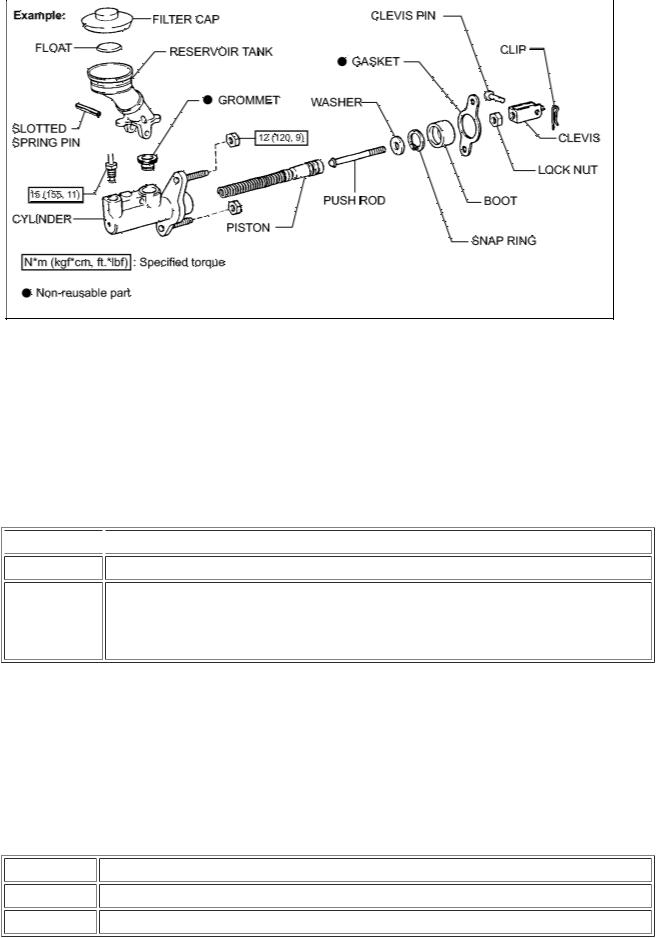
(c) Torque specifications, grease application areas and non-reusable parts are emphasized in the procedures.
HINT:
There are cases where such information can only be explained by using an illustration. In these cases, torque, oil and other information are described in the illustration.
(d) Only items with key points are described in the text. What to do and other details are explained using illustrations next to the text. Both the text and illustrations are accompanied by standard values and notices.
 Illustration
Task heading
Explanation text
 What to do and where to do it
What work will be performed
 How to perform the task
 Information such as specifications and warnings, which are written in boldface text
(e)Illustrations of similar vehicle models are sometimes used. In these cases, minor details may be different from the actual vehicle.
(f)Procedures are presented in a step-by-step format.
5.SERVICE SPECIFICATIONS
(a)Specifications are presented in boldface text throughout the manual. The specifications are also found in the "Service Specifications" section for reference.
6.TERM DEFINITIONS
CAUTION |
Possibility of injury to you or other people. |
NOTICE |
Possibility of damage to components being repaired. |
HINT |
Provides additional information to help you perform repairs. |
7. INTERNATIONAL SYSTEM OF UNITS

(a) The units used in this manual comply with the International System of Units (SI UNIT) standard. Other units from the metric system and the English systems are also provided.
Example:
Torque: 30 N·m (310 kgf·cm, 22ft·lbf)
Last Modified: 3-27-2012 |
6.4 F |
From: 201203 |
||
Model Year: 2013 |
|
|
Model: FR-S |
Doc ID: RM000000UZB09AX |
Title: INTRODUCTION: TERMS: ABBREVIATIONS USED IN MANUAL (2013 FR-S) |
||||
ABBREVIATIONS USED IN MANUAL |
||||
|
|
|
|
|
ABBREVIATION |
|
|
|
MEANING |
|
|
|
|
|
ABS |
|
Anti-Lock Brake System |
|
|
A/C |
|
Air Conditioner |
|
|
AC |
|
Alternating Current |
|
|
ACC |
|
Accessory |
|
|
ACIS |
|
Acoustic Control Induction System |
|
|
ACM |
|
Active Control Engine Mount |
|
|
ACSD |
|
Automatic Cold Start Device |
|
|
ACT |
|
Actuator |
|
|
A.D.D |
|
Automatic Disconnecting Differential |
|
|
ADM |
|
P.T. Astra Daihatsu Motor |
|
|
A/F |
|
Air-Fuel Ratio |
|
|
AFS |
|
Adaptive Front-Lighting System |
|
|
AHC |
|
Active Height Control Suspension |
|
|
AID |
|
Air Injection Control Driver |
|
|
ALR |
|
Automatic Locking Retractor |
|
|
ALT |
|
Alternator |
|
|
AMP |
|
Amplifier |
|
|
ANT |
|
Antenna |
|
|
ASG |
|
Automated Sequential Gearbox |
|
|
ASL |
|
Automatic Sound Levelizer |
|
|
ASSB |
|
Assembly Services Sdn. Bhd. |
|
|
A/T, ATM |
|
Automatic Transmission (Transaxle) |
|
|
A-TRAC, A-TRC |
|
Active Traction Control |
|
|
ATDC |
|
After Top Dead Center |
|
|
ATF |
|
Automatic Transmission Fluid |
|
|
AUTO |
|
Automatic |
|
|
AUX |
|
Auxiliary |
|
|
AVG |
|
Average |
|
|
AVS |
|
Adaptive Variable Suspension |
|
|
AWD |
|
All Wheel Drive |
|
|
B+, +B |
|
Battery Voltage |
|
|

BA |
Brake Assist |
BACS |
Boost Altitude Compensation System |
BATT |
Battery |
BDC |
Bottom Dead Center |
B/L |
Bi-Level |
B/S |
Bore-Stroke Ratio |
BTDC |
Before Top Dead Center |
BVSV |
Bimetallic Vacuum Switching Valve |
Calif. |
California |
CAN |
Controller Area Network |
CB |
Circuit Breaker |
CCM |
Carbon Ceramic Material |
CCo |
Catalytic Converter for Oxidation |
CCV |
Canister Closed Valve |
CD |
Compact Disc |
CF |
Cornering Force |
CG |
Center of Gravity |
CH |
Channel |
CKD |
Complete Knock Down |
CNG |
Compressed Natural Gas |
COMB. |
Combination |
CPS |
Combustion Pressure Sensor |
CPU |
Central Processing Unit |
CRAWL |
Crawl Control |
CRS |
Child Restraint System |
CTR |
Center |
C/V |
Check Valve |
CV |
Control Valve |
CVT |
Continuously Variable Transmission (Transaxle) |
CW |
Curb Weight |
DC |
Direct Current |
DEF |
Defogger |
DFL |
Deflector |
DIFF. |
Differential |
DIFF. LOCK |
Differential Lock |
D/INJ |
Direct Injection |
DLC |
Data Link Connector |

DLI |
Distributorless Ignition |
|
DOHC |
Double Overhead Camshaft |
|
DP |
Dash Pot |
|
DS |
Dead Soak |
|
DSP |
Digital Signal Processor |
|
DTC |
Diagnostic Trouble Code |
|
DVD |
Digital Versatile Disc |
|
EBD |
Electric Brake Force Distribution |
|
EC |
Electrochromic |
|
ECAM |
Engine Control And Measurement System |
|
ECD |
Electronically Controlled Diesel |
|
ECDY |
Eddy Current Dynamometer |
|
ECT |
Electronic Controlled Automatic Transmission |
|
ECU |
Electronic Control Unit |
|
ED |
Electro-Deposited |
|
EDU |
Electronic Driving Unit |
|
EDIC |
Electric Diesel Injection Control |
|
EFI |
Electronic Fuel Injection |
|
E/G |
Engine |
|
EGR |
Exhaust Gas Recirculation |
|
ELR |
Emergency Locking Retractor |
|
EMPS |
Electric Motor Power Steering |
|
EPS |
Electric Power Steering |
|
ENG |
Engine |
|
ES |
Easy & Smooth |
|
ESA |
Electronic Spark Advance |
|
EVAP |
Evaporative Emission Control |
|
E-VRV |
Electric Vacuum Regulating Valve |
|
EX |
Exhaust |
|
FE |
Fuel Economy |
|
FF |
Front-Engine-Front-Wheel-Drive |
|
F/G |
Fuel Gauge |
|
FIPG |
Formed In Place Gasket |
|
FL |
Fusible Link |
|
Front Left |
||
|
||
F/P |
Fuel Pump |
|
FR |
Front |
|
|

|
Front Right |
F/W |
Flywheel |
FW/D |
Flywheel Damper |
FWD |
Front Wheel Drive |
GAS |
Gasoline |
GND |
Ground |
GPS |
Global Positioning System |
GSA |
Gear Shift Actuator |
GTMC |
Gac Toyota Motor Co., Ltd. |
GTS |
Global TechStream |
H/B |
Hatchback |
H-FUSE |
High Current Fuse |
HID |
High Intensity Discharge (Headlight) |
HPU |
Hydraulic Power Unit |
HSG |
Housing |
HT |
Hard Top |
HV |
Hybrid Vehicle |
HWS |
Heated Windshield System |
IC |
Integrated Circuit |
IDI |
Indirect Diesel Injection |
IFS |
Independent Front Suspension |
IG |
Ignition |
IIA |
Integrated Ignition Assembly |
IMC |
INDUS Motor Company Ltd. |
IN |
Intake (Manifold, Valve) |
INT |
Intermittent |
I/P |
Instrument Panel |
IRS |
Independent Rear Suspension |
ISC |
Idle Speed Control |
ISCV |
Idle Speed Control Valve |
KD |
Kick-Down |
KDSS |
Kinetic Dynamic Suspension System |
LAN |
Local Area Network |
LCD |
Liquid Crystal Display |
LED |
Light Emitting Diode |
LEV |
Low Emission Vehicle |
LH |
Left-Hand |
LHD |
Left-Hand Drive |
LIN |
Local Interconnect Network |
L/H/W |
Length, Height, Width |
LLC |
Long-Life Coolant |
LNG |
Liquefied Natural Gas |
LPG |
Liquefied Petroleum Gas |
LSD |
Limited Slip Differential |
LSP & BV |
Load Sensing Proportioning and Bypass Valve |
LSPV |
Load Sensing Proportioning Valve |
MAP |
Manifold Absolute Pressure |
MAX. |
Maximum |
MIC |
Microphone |
MIL |
Malfunction Indicator Lamp |
MIN. |
Minimum |
MG1 |
Motor Generator No. 1 |
MG2 |
Motor Generator No. 2 |
MMT |
Multi-mode Manual Transmission |
MP |
Multipurpose |
MPI |
Multipoint Electronic Injection |
MPX |
Multiplex Communication System |
M/T |
Manual Transmission (Transaxle) |
MT |
Mount |
MTG |
Mounting |
N |
Neutral |
NA |
Natural Aspiration |
NO. |
Number |
O2S |
Oxygen Sensor |
OC |
Oxidation Catalyst |
OCV |
Oil Control Valve |
O/D |
Overdrive |
OEM |
Original Equipment Manufacturing |
OPT |
Option |
ORVR |
On-board Refilling Vapor Recovery |
O/S |
Oversize |
P & BV |
Proportioning and Bypass Valve |
PBD |
Power Back Door |
PCS |
Power Control System |
|

|
Pre-crash Safety System/Pre-collision System |
PCV |
Positive Crankcase Ventilation |
PKB |
Parking Brake |
PPS |
Progressive Power Steering |
PROM |
Programmable Read Only Memory |
PS |
Power Steering |
PSD |
Power Slide Door |
PTC |
Positive Temperature Coefficient |
PTO |
Power Take-Off |
PZEV |
Partial Zero Emission Vehicle |
P/W |
Power Window |
R & P |
Rack and Pinion |
RAM |
Random Access Memory |
RBS |
Recirculating Ball Type Steering |
REAS |
Relative Absorber System |
R/F |
Reinforcement |
RFS |
Rigid Front Suspension |
RH |
Right-Hand |
RHD |
Right-Hand Drive |
RL |
Rear Left |
ROM |
Read Only Memory |
|
Rear |
RR
Rear Right
RRS |
Rigid Rear Suspension |
|
RSE |
Rear Seat Entertainment |
|
RWD |
Rear Wheel Drive |
|
SC |
Supercharger |
|
SCV |
Swirl Control Valve (for gasoline engine) |
|
Suction Control Valve (for diesel engine) |
||
|
||
SFTM |
Sichuan Faw Toyota Motor Co., Ltd. |
|
SIA |
Subaru of Indiana Automotive, Inc. |
|
SICS |
Starting Injection Control System |
|
SLLC |
Super Long Life Coolant |
|
SOC |
State Of Charge |
|
SOHC |
Single Overhead Camshaft |
|
SPEC |
Specification |
|
SPI |
Single Point Injection |

SPV |
Spill Control Valve |
|
SRS |
Supplemental Restraint System |
|
SSM |
Special Service Materials |
|
SST |
Special Service Tools |
|
STD |
Standard |
|
STJ |
Cold-Start Fuel Injection |
|
SULEV |
Super Ultra Low Emission Vehicle |
|
T/A |
Transaxle |
|
TACH |
Tachometer |
|
TASA |
Toyota Argentina S.A. |
|
TCAP |
Toyota Caetano Portugal, S.A. |
|
TCM |
Transmission Control Module |
|
TCV |
Timing Control Valve (for diesel engine) |
|
Tumble Control Valve (for gasoline engine) |
||
|
||
TDB |
Toyota do Brasil Ltda. |
|
TDC |
Top Dead Center |
|
TDV |
Toyota de Venezuela, C.A. |
|
TEMP. |
Temperature |
|
TFT |
TOYOTA Free-Tronic |
|
TFTM |
Tianjin Faw Toyota Motor Co., Ltd. |
|
THS ll |
TOYOTA Hybrid System ll |
|
TIS |
Total Information System for Vehicle Development |
|
T/M |
Transmission |
|
TMC |
Toyota Motor Corporation |
|
TMCA |
Toyota Motor Corporation Australia Ltd. |
|
TMMBC |
Toyota Motor Manufacturing de Baja California, S. de R.L. de C.V. |
|
TMMC |
Toyota Motor Manufacturing Canada Inc. |
|
TMMF |
Toyota Motor Manufacturing France S.A.S. |
|
TMMI |
Toyota Motor Manufacturing, Indiana, Inc. |
|
TMMIN |
P.T. Toyota Motor Manufacturing Indonesia |
|
TMMK |
TOYOTA Motor Manufacturing Kentucky, Inc. |
|
TMMR |
Toyota Motor Manufacturing Russia |
|
TMMT |
Toyota Motor Manufacturing Turkey Inc. |
|
TMMTX |
Toyota Motor Manufacturing, Texas, Inc. |
|
TMUK |
Toyota Motor Manufacturing (UK) Ltd. |
|
TMP |
Toyota Motor Philippines Corp. |
|
TMT |
Toyota Motor Thailand Co. Ltd. |

TMV |
Toyota Motor Vietnam Co., Ltd. |
TPCA |
Toyota Peugeot Citroen Automobiles Czech, s.r.o. |
TRAC/TRC |
Traction Control System |
TSAM |
Toyota South Africa Motors (Pty) Ltd. |
TVIP |
TOYOTA Vehicle Intrusion Protection |
TWC |
Three-Way Catalyst |
U/D |
Underdrive |
U/S |
Undersize |
VCV |
Vacuum Control Valve |
VDIM |
Vehicle Dynamics Integrated Management |
VENT |
Ventilator |
VGRS |
Variable Gear Ratio Steering |
VIM |
Vehicle Interface Module |
VIN |
Vehicle Identification Number |
VLC |
Valve Lift Control |
VPS |
Variable Power Steering |
VSC |
Vehicle Stability Control |
VSV |
Vacuum Switching Valve |
VTV |
Vacuum Transmitting Valve |
VVT-i |
Variable Valve Timing-intelligent |
W/, w/ |
With |
WGN |
Wagon |
W/H |
Wire Harness |
W/O, w/o |
Without |
X-REAS |
X-Relative Absorber System |
1ST, 1st |
First |
2ND, 2nd |
Second |
2WD |
Two Wheel Drive Vehicle (4 x 2) |
3RD, 3rd |
Third |
4TH, 4th |
Fourth |
4WD |
Four Wheel Drive Vehicle (4 x 4) |
4WS |
Four Wheel Steering System |
5TH, 5th |
Fifth |
6TH, 6th |
Sixth |
7TH, 7th |
Seventh |
8TH, 8th |
Eighth |
Last Modified: 3-27-2012 |
6.4 F |
From: 201203 |
Model Year: 2013 |
Model: FR-S |
Doc ID: RM00000286702CX |
 Title: INTRODUCTION: TERMS: GLOSSARY OF SAE AND SCION TERMS (2013 FR-S)
GLOSSARY OF SAE AND SCION TERMS
This glossary lists all SAE-J1930 terms and abbreviations used in this manual in compliance with SAE recommendations, as well as their SCION equivalents.
SAE |
|
SAE TERM |
|
SCION TERM |
ABBREVIATION |
|
|
|
( )-ABBREVIATION |
|
|
|
|
|
A/C |
|
Air Conditioning |
|
Air Conditioner |
ACL |
|
Air Cleaner |
|
Air Cleaner, A/CL |
AIR |
|
Secondary Air Injection |
|
Air Injection (AI) |
AP |
|
Accelerator Pedal |
- |
|
B+ |
|
Battery Positive Voltage |
|
+B, Battery Voltage |
BARO |
|
Barometric Pressure |
- |
|
CAC |
|
Charge Air Cooler |
|
Intercooler |
CARB |
|
Carburetor |
|
Carburetor |
CFI |
|
Continuous Fuel Injection |
- |
|
CKP |
|
Crankshaft Position |
|
Crank Angle |
CL |
|
Closed Loop |
|
Closed Loop |
CMP |
|
Camshaft Position |
|
Cam Angle |
CPP |
|
Clutch Pedal Position |
- |
|
CTOX |
|
Continuous Trap Oxidizer |
- |
|
CTP |
|
Closed Throttle Position |
|
LL ON, Idle ON |
DFI |
|
Direct Fuel Injection |
|
Direct Injection (DI./INJ) |
DI |
|
Distributor Ignition |
- |
|
DLC3 |
|
Data Link Connector 3 |
|
OBD II Diagnostic Connector |
DTC |
|
Diagnostic Trouble Code |
|
Diagnostic Trouble Code |
DTM |
|
Diagnostic Test Mode |
- |
|
ECL |
|
Engine Coolant Level |
- |
|
ECM |
|
Engine Control Module |
|
Engine Electronic Control Unit (ECU) |
ECT |
|
Engine Coolant Temperature |
|
Coolant Temperature, Water Temperature |
|
|
(THW) |
||
|
|
|
|
|
EEPROM |
|
Electrically Erasable Programmable Read |
|
Electrically Erasable Programmable Read |
|
Only Memory |
|
Only Memory (EEPROM) |
|
|
|
|
||
EFE |
|
Early Fuel Evaporation |
|
Cold Mixture Heater (CMH), Heat Control |
|
|
Valve (HCV) |
||
|
|
|
|
|
EGR |
|
Exhaust Gas Recirculation |
|
Exhaust Gas Recirculation (EGR) |

EI |
Electronic Ignition |
Distributorless Ignition (DLI) |
|
EM |
Engine Modification |
Engine Modification (EM) |
|
EPROM |
Erasable Programmable Read Only |
Programmable Read Only Memory (PROM) |
|
Memory |
|||
|
|
||
EVAP |
Evaporative Emission |
Evaporative Emission Control (EVAP) |
|
FC |
Fan Control |
- |
|
FEEPROM |
Flash Electrically Erasable Programmable |
- |
|
|
Read Only Memory |
|
|
FEPROM |
Flash Erasable Programmable Read Only |
- |
|
Memory |
|||
|
|
||
FF |
Flexible Fuel |
- |
|
FP |
Fuel Pump |
Fuel Pump |
|
GEN |
Generator |
Alternator |
|
GND |
Ground |
Ground (GND) |
|
HO2S |
Heated Oxygen Sensor |
Heated Oxygen Sensor (HO 2 S) |
|
IAC |
Idle Air Control |
Idle Speed Control (ISC) |
|
IAT |
Intake Air Temperature |
Intake or Inlet Air Temperature |
|
ICM |
Ignition Control Module |
- |
|
IFI |
Indirect Fuel Injection |
Indirect Injection (IDL) |
|
IFS |
Inertia Fuel-Shutoff |
- |
|
ISC |
Idle Speed Control |
- |
|
KS |
Knock Sensor |
Knock Sensor |
|
MAF |
Mass Airflow |
Air Flow Meter |
|
MAP |
Manifold Absolute Pressure |
Manifold Pressure Intake Vacuum |
|
|
|
Electric Bleed Air Control Valve (EBCV) |
|
MC |
Mixture Control |
Mixture Control Valve (MCV) |
|
|
|
Electric Air Control Valve (EACV) |
|
MDP |
Manifold Differential Pressure |
- |
|
MFI |
Multiport Fuel Injection |
Electronic Fuel Injection (EFI) |
|
MIL |
Malfunction Indicator Lamp |
Check Engine Light |
|
MST |
Manifold Surface Temperature |
- |
|
MVZ |
Manifold Vacuum Zone |
- |
|
NVRAM |
Non-Volatile Random Access Memory |
- |
|
O2S |
Oxygen Sensor |
Oxygen Sensor, O 2 Sensor (O 2 S) |
|
OBD |
On-Board Diagnostic |
On-Board Diagnostic System (OBD) |
|
OC |
Oxidation Catalytic Converter |
Oxidation Catalytic Convert (OC), CCo |
|
OL |
Open Loop |
Open Loop |
|
PAIR |
Pulsed Secondary Air Injection |
Air Suction (AS) |
|
PCM |
Powertrain Control Module |
- |

PNP |
Park/Neutral Position |
PROM |
Programmable Read Only Memory |
PSP |
Power Steering Pressure |
PTOX |
Periodic Trap Oxidizer |
RAM |
Random Access Memory |
RM |
Relay Module |
ROM |
Read Only Memory |
RPM |
Engine Speed |
SC |
Supercharger |
SCB |
Supercharger Bypass |
SFI |
Sequential Multiport Fuel Injection |
SPL |
Smoke Puff Limiter |
SRI |
Service Reminder Indicator |
SRT |
System Readiness Test |
ST |
Scan Tool |
TB |
Throttle Body |
TBI |
Throttle Body Fuel Injection |
TC |
Turbocharger |
TCC |
Torque Converter Clutch |
TCM |
Transmission Control Module |
TP |
Throttle Position |
TR |
Transmission Range |
TVV |
Thermal Vacuum Valve |
TWC |
Three-Way Catalytic Converter |
 -
-
-
 -
-
Diesel Particulate Filter (DPF)
Diesel Particulate Trap (DPT)
 Random Access Memory (RAM)
-
 Read Only Memory (ROM)
Engine Speed
 Supercharger
E-ABV
Electronic Fuel Injection (EFI), Sequential Injection
 -
-
-
 -
-
-
 Throttle Body
Single Point Injection Central Fuel Injection (Ci)
 Turbocharger
Torque Converter
 Transmission ECU, ECT ECU
Throttle Position
 -
-
Bimetallic Vacuum Switching Valve (BVSV) Thermostatic Vacuum Switching Valve (TVSV)
Three-Way Catalytic (TWC)
Manifold Converter
CC RO
TWC+OC |
Three-Way + Oxidation Catalytic |
CC R + CCo |
|
Converter |
|||
|
|
||
VAF |
Volume Airflow |
Air Flow Meter |
|
VR |
Voltage Regulator |
Voltage Regulator |
|
VSS |
Vehicle Speed Sensor |
Vehicle Speed Sensor |
|
WOT |
Wide Open Throttle |
Full Throttle |
|
WU-OC |
Warm Up Oxidation Catalytic Converter |
- |
|
WU-TWC |
Warm Up Three-Way Catalytic Converter |
- |
3GR |
Third Gear |
- |
4GR |
Fourth Gear |
- |
Last Modified: 3-27-2012 |
6.4 F |
From: 201203 |
Model Year: 2013 |
Model: FR-S |
Doc ID: RM000000UYW0DPX |
Title: INTRODUCTION: IDENTIFICATION INFORMATION: VEHICLE IDENTIFICATION AND SERIAL NUMBERS (2013 FR-S)
VEHICLE IDENTIFICATION AND SERIAL NUMBERS
1.VEHICLE IDENTIFICATION NUMBER
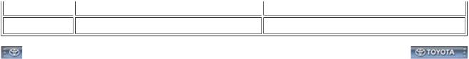
(a)The vehicle identification number is stamped on the vehicle body and on the certification label as shown in the illustration.
Text in Illustration |
|
|
|
*A |
Manual transmission |
- |
- |
*1 |
Vehicle Identification Number |
*2 |
Certification Label |
2.ENGINE SERIAL NUMBER AND TRANSMISSION SERIAL NUMBER
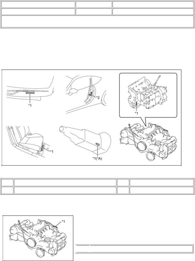
(a)The engine serial number is stamped on the cylinder block of the engine as shown in the illustration.
Text in Illustration
 *1
*1  FA20 Engine Serial Number
(b) The transmission serial number is printed on the transmission number label.
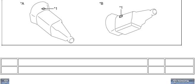
Text in Illustration |
|
|
|
*A |
TL70 |
*B |
TX6A |
*1 |
Transmission Number Label |
- |
- |
Last Modified: 3-27-2012 |
6.4 F |
From: 201203 |
Model Year: 2013 |
Model: FR-S |
Doc ID: RM000000UZ30BTX |
Title: INTRODUCTION: HOW TO TROUBLESHOOT ECU CONTROLLED SYSTEMS: ELECTRONIC CIRCUIT INSPECTION PROCEDURE (2013 FR-S)
ELECTRONIC CIRCUIT INSPECTION PROCEDURE
1.BASIC INSPECTION
(a)WHEN MEASURING RESISTANCE OF ELECTRONIC PARTS
(1)Unless otherwise stated, all resistance measurements are standard values measured at an ambient temperature of 20°C (68°F). Resistance measurements may be inaccurate if measured at high temperatures, i.e. immediately after the vehicle has been running. Measurements should be made after the engine has cooled down.
(b) HANDLING CONNECTORS
Text in Illustration
*a INCORRECT *b  CORRECT
(1)When disconnecting a connector, first squeeze the mating connector housing halves tightly together to release the lock, and then press the lock claw and separate the connector.
(2)When disconnecting a connector, do not pull on the harnesses. Grasp the connector directly and separate it.
(3)Before connecting a connector, check that there are no deformations, damage, looseness or missing terminals.
(4)When connecting a connector, press firmly until it locks with a "click" sound.
(5)If checking a connector with a TOYOTA electrical tester, check the connector from the backside (harness side) using a mini test lead.
NOTICE:
 As a waterproof connector cannot be checked from the backside, check it by connecting a sub-harness.
 Do not damage the terminals by moving the inserted tester needle.
(c) CHECKING CONNECTORS
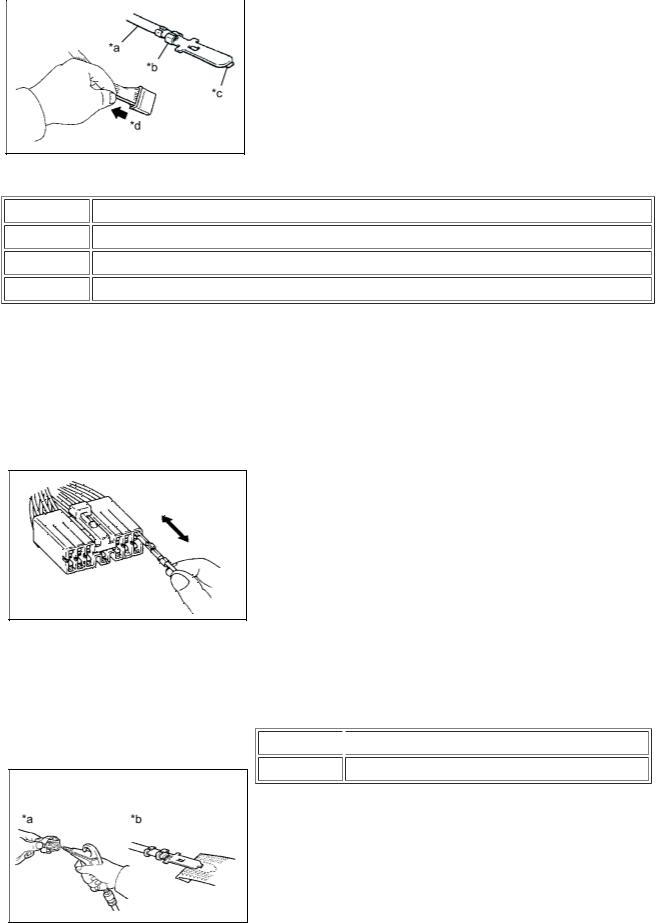
Text in Illustration
*a |
Core Wire |
*b |
Looseness of Crimping |
*c |
Terminal Deformation |
*d |
Pull Lightly |
(1)Checking when a connector is connected: Squeeze the connectors together to confirm that they are fully connected and locked.
(2)Checking when a connector is disconnected: Check by pulling the wire harness lightly from the backside of the connector. Look for unlatched terminals, missing terminals, loose crimps or broken conductor wires. Visually check for corrosion, metallic or foreign matter and water, and bent, rusted, overheated, contaminated or deformed terminals.
(3)Checking the contact pressure of the terminal: Prepare a spare male terminal. Insert it into a female terminal, and check for ample tension when inserting and after full engagement.
NOTICE:
When testing a gold-plated female terminal, always use a gold-plated male terminal.
(d) CONNECTOR TERMINAL REPAIR METHOD
Text in Illustration
*a  CORRECT *b INCORRECT
(1)If there is any foreign matter on the terminal, clean the contact point with compressed air or a cloth. Never rub the contact point using sandpaper as the plating may come off.
(2)If there is abnormal contact pressure, replace the female terminal. If the male terminal is gold-plated (gold color), use a gold-plated female terminal; if it is silver-plated (silver color), use a silver-plated female terminal.
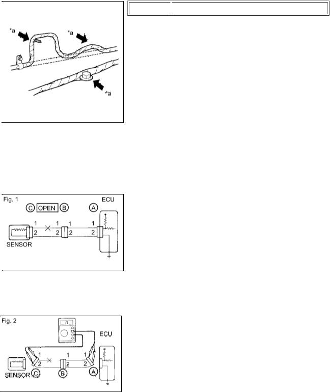
2. CHECK FOR OPEN CIRCUIT
(b) Check the resistance.
(3)Damaged, deformed or corroded terminals should be replaced. If the terminal does not lock into the housing, the housing may have to be replaced.
(e)WIRE HARNESS HANDLING
Text in Illustration
*a  INCORRECT
(1)If removing a wire harness, check the wiring and clamps before proceeding so that it can be restored in the same way.
(2)Never twist, pull or slacken the wire harness more than necessary.
(3)The wire harness should never come into contact with any high temperature part, rotating, moving, vibrating or sharp-edged parts. Avoid contact with panel edges, screw tips and other sharp items.
(4)When installing parts, never pinch the wire harness.
(5)Never cut or break the cover of the wire harness. If it is cut or broken, repair it with insulating tape or replace the wire harness.
(a) For an open circuit in the wire harness in Fig. 1, measure the resistance and voltage as follows:
(1)Disconnect connectors A and C and measure the resistance between the terminals of the connectors.
Standard Resistance (Fig. 2): |
|
|
|
|
|
TESTER CONNECTION |
|
SPECIFIED CONDITION |
|
|
|
Connector A terminal 1 - Connector C terminal 1 |
|
10 kΩ or higher |
Connector A terminal 2 - Connector C terminal 2 |
|
Below 1 Ω |
HINT:
Measure the resistance while lightly shaking the wire harness vertically and horizontally.
If the results match the values specified above, an open circuit exists between terminal 1 of connector A and terminal 1 of connector C.
(2)Disconnect connector B and measure the resistance between the terminals of the connectors.
Standard Resistance (Fig. 3):
TESTER CONNECTION
Connector A terminal 1 - Connector B1 terminal 1
Connector B2 terminal 1 - Connector C terminal 1
SPECIFIED
CONDITION
Below 1 Ω
10 kΩ or higher
If the results match the values specified above, an open circuit exists between terminal 1 of connector B2 and terminal 1 of connector C.
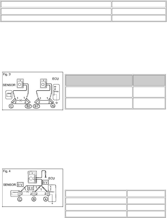
(c)Check the voltage.
(1)In a circuit in which voltage is applied to the ECU connector terminal, an open circuit can be checked by conducting a voltage check.
With each connector still connected, measure the voltage between body ground and the following terminals (in this order): 1) terminal 1 of connector A, 2) terminal 1 of connector B, and 3) terminal 1 of connector C.
Standard Voltage (Fig. 4):
TESTER CONNECTION |
|
SPECIFIED CONDITION |
|
|
|
Connector A terminal 1 - Body ground |
|
5 V |
Connector B terminal 1 - Body ground |
|
5 V |
Connector C terminal 1 - Body ground |
|
Below 1 V |
If the results match the values specified above, an open circuit exists in the wire harness between terminal 1 of connector B and terminal 1 of connector C.

3. CHECK FOR SHORT CIRCUIT
(a) If a wire in the harness is shorted to ground (Fig. 5), locate the shorted section by measuring the resistance as follows:
(b) Check the resistance to body ground.
(1) Disconnect connectors A and C and measure the resistance.
Standard Resistance (Fig. 6): |
|
|
|
|
|
TESTER CONNECTION |
|
SPECIFIED CONDITION |
|
|
|
Connector A terminal 1 - Body ground |
|
Below 1 Ω |
Connector A terminal 2 - Body ground |
|
10 kΩ or higher |
HINT:
Measure the resistance while lightly shaking the wire harness vertically and horizontally.
If the results match the values specified above, a short circuit exists between terminal 1 of connector A and terminal 1 of connector C.
(2) Disconnect connector B and measure the resistance.
Standard Resistance (Fig. 7): |
|
|
|
|
|
TESTER CONNECTION |
|
SPECIFIED |
|
|
CONDITION |
|
|
|
Connector A terminal 1 - Body ground |
|
10 kΩ or higher |
Connector B2 terminal 1 - Body |
|
Below 1 Ω |
ground |
|
|
|
|
If the results match the values specified above, a
short circuit exists between terminal 1 of connector B2 and terminal 1 of connector C.
4. CHECK AND REPLACE ECU
NOTICE:
 The connector should not be disconnected from the ECU. Perform the inspection from the backside of the connector on the wire harness side.
 When no measuring condition is specified, perform the inspection with the engine stopped and the ignition switch ON.
 Check that the connectors are fully seated. Check for loose, corroded or broken wires.
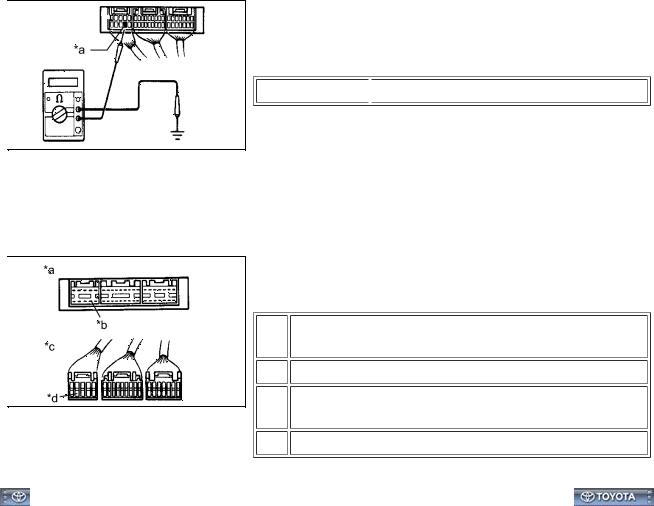
(a) First, check the ECU ground circuit. If it is faulty, repair it. If it is normal, the ECU could be faulty. Temporarily replace the ECU with a normally functioning one and check if the symptoms occur. If the trouble symptoms disappear, replace the original ECU.
(1)Measure the resistance between the ECU ground terminal and body ground.
Text in Illustration
*a  Ground
Standard resistance:
Below 1 Ω
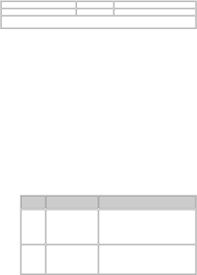
(2)Disconnect the ECU connector. Check the ground terminals on the ECU side and wire harness side for bent terminals, corrosion or foreign matter. Lastly, check the contact pressure of the female terminals.
Text in Illustration
*a |
Component without harness connected |
|
(ECU) |
*b |
Ground |
*c |
Front view of wire harness connector |
|
(to ECU) |
*d |
Ground |
Last Modified: 3-27-2012 |
6.4 F |
From: 201203 |
Model Year: 2013 |
Model: FR-S |
Doc ID: RM000000UZ20BWX |
Title: INTRODUCTION: HOW TO TROUBLESHOOT ECU CONTROLLED SYSTEMS: GENERAL INFORMATION (2013 FR-S)
GENERAL INFORMATION
A large number of ECU controlled systems are used in this vehicle. In general, ECU controlled systems are considered to be very intricate, requiring a high level of technical knowledge to troubleshoot. However, most problem checking procedures only involve inspecting the ECU controlled system circuits one by one. An adequate understanding of the system and a basic knowledge of electricity is enough to perform effective troubleshooting, accurate diagnosis and necessary repairs.
(For using the Techstream*)
HINT:
*: The Techstream is the name for the diagnostic tester in North America.
 Before using the Techstream, read the operator's manual thoroughly.
 If the Techstream cannot communicate with the ECU controlled systems when connected to the DLC3 with the ignition switch ON and the Techstream turned on, there is a problem on the vehicle side or the Techstream side.
i.If communication is possible when the Techstream is connected to another vehicle, inspect the diagnosis data link line (bus (+) line), CANH and CANL lines, and the power circuits for the vehicle ECUs.
ii.If communication is still not possible when the Techstream is connected to another vehicle, the problem is probably in the Techstream itself. Perform the Self Test procedure outlined in the Techstream operator's manual.
1.TROUBLESHOOTING PROCEDURES
 The troubleshooting procedures consist of diagnosis procedures for when a DTC is stored and diagnosis procedures for when no DTC is stored. The basic idea is explained in the following table.
PROCEDURE
TYPE
DTC Based
Diagnosis
Symptom
Based
Diagnosis
(No DTCs
stored)
DETAILS
The diagnosis procedure is based on the DTC that is stored.
The diagnosis procedure is based on problem symptoms.
TROUBLESHOOTING METHOD
The malfunctioning part is identified based on the DTC detection conditions using a process of elimination.
The possible trouble areas are eliminated one-by- one by use of the Techstream and inspection of related parts.
The malfunctioning part is identified based on the problem symptoms using a process of elimination. The possible trouble areas are eliminated one-by- one by use of the Techstream and inspection of related parts.
 Vehicle systems are complex and use many ECUs that are difficult to inspect independently. Therefore, a process of elimination is used, where components that can be inspected
individually are inspected, and if no problems are found in these components, the related ECU is identified as the problem and replaced.
 It is extremely important to ask the customer about the environment and the conditions present when the problem occurred (Customer Problem Analysis). This makes it possible to simulate the conditions and confirm the symptom. If the symptom cannot be confirmed or the DTC does not recur, the malfunctioning part may not be identified using the troubleshooting procedure, and the ECU for the related system may be replaced even though it is not defective. If this happens, the original problem will not be solved.
 In order to prevent endless expansion of troubleshooting procedures, the troubleshooting procedures are written with the assumption that multiple malfunctions do not occur simultaneously for a single problem symptom.
 To identify the malfunctioning part, troubleshooting procedures narrow down the target by separating components, ECUs and wire harnesses during the inspection. If the wire harness is identified as the cause of the problem, it is necessary to inspect not only the connections to components and ECUs but also all of the wire harness connectors between the component and the ECU.
2.DESCRIPTION
(a)The data of each system and Diagnostic Trouble Codes (DTCs) can be read from the Data Link Connector 3 (DLC3) of the vehicle. When the system seems to be malfunctioning, use the Techstream to check for malfunctions and perform repairs.
3.CHECK DLC3
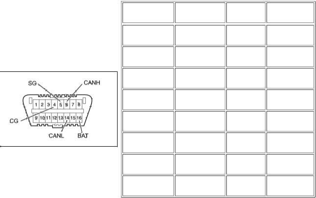
(a) The vehicle ECUs use ISO 15765-4 communication protocol. The terminal arrangement of the DLC3 complies with SAE J1962 and matches the ISO 15765-4 format.
TERMINAL NO. |
|
TERMINAL |
|
CONDITION |
|
SPECIFIED |
(SYMBOL) |
|
DESCRIPTION |
|
|
|
CONDITION |
|
|
|
|
|
|
|
4 (CG) - Body |
|
Chassis ground |
|
Always |
|
Below 1 Ω |
ground |
|
|
|
|||
|
|
|
|
|
|
|
5 (SG) - Body |
|
Signal ground |
|
Always |
|
Below 1 Ω |
ground |
|
|
|
|||
|
|
|
|
|
|
|
16 (BAT) - |
|
Battery positive |
|
Always |
|
11 to 14 V |
Body ground |
|
|
|
|||
|
|
|
|
|
|
|
6 (CANH) - 14 |
|
CAN bus line |
|
Ignition |
|
57 to 63 Ω |
(CANL) |
|
|
switch off* |
|
||
6 (CANH) - 4 |
|
HIGH-level CAN |
|
Ignition |
|
200 Ω or |
(CG) |
|
bus line |
|
switch off* |
|
higher |
14 (CANL) - 4 |
|
LOW-level CAN |
|
Ignition |
|
200 Ω or |
(CG) |
|
bus line |
|
switch off* |
|
higher |
6 (CANH) - 16 |
|
HIGH-level CAN |
|
Ignition |
|
6 kΩ or higher |
(BAT) |
|
bus line |
|
switch off* |
|
|
14 (CANL) - 16 |
|
LOW-level CAN |
|
Ignition |
|
6 kΩ or higher |
(BAT) |
|
bus line |
|
switch off* |
|
|
NOTICE: |
|
|
|
|
|
|
*: Before measuring the resistance, leave the vehicle as is for at least 1 minute and do not operate the ignition switch, any other switches or the doors.

If the result is not as specified, the DLC3 may have a malfunction. Repair or replace the harness or connector.
Last Modified: 3-27-2012 |
6.4 D |
From: 201203 |
Model Year: 2013 |
Model: FR-S |
Doc ID: RM000000UZ1088X |
Title: INTRODUCTION: HOW TO TROUBLESHOOT ECU CONTROLLED SYSTEMS: HOW TO PROCEED WITH TROUBLESHOOTING (2013 FR-S)
HOW TO PROCEED WITH TROUBLESHOOTING
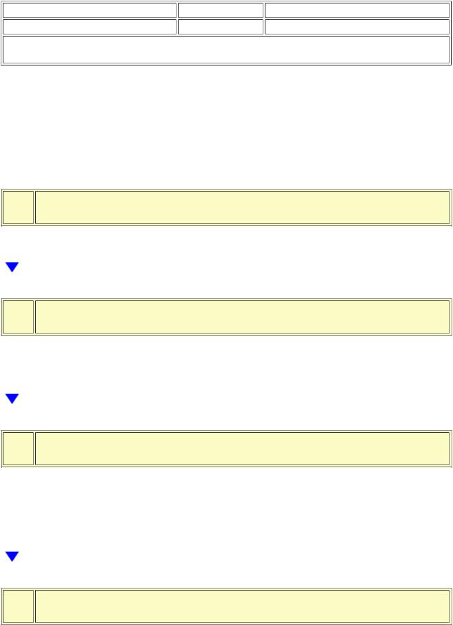
1. OPERATION FLOW
HINT:
Perform troubleshooting in accordance with the procedure below. The following is an outline of basic troubleshooting procedure. Confirm the troubleshooting procedure for the circuit you are working on before beginning troubleshooting.
1.VEHICLE BROUGHT TO WORKSHOP
NEXT
2.CUSTOMER PROBLEM ANALYSIS
(a)Ask the customer about the conditions and environment when the problem occurred.
NEXT
3.INSPECT BATTERY VOLTAGE
Standard voltage: 11 to 14 V
If the voltage is below 11 V, recharge or replace the battery before proceeding to the next step.
NEXT
4.SYMPTOM CONFIRMATION AND DTC (AND FREEZE FRAME DATA) CHECK
(a)Visually check the wire harnesses, connectors and fuses for open and short circuits.
(b)Warm up the engine to the normal operating temperature.
Loading...