


BMS-TP0640ACE

BMS-TP0640ACE
BMS-TP5120ACE
INSTALLATION MANUAL
TOUCH SCREEN CONTROLLER
for Air Conditioning Control System
• Thank you very much for purchasing the TOSHIBA Touch Screen Controller.
• Please read this manual carefully beforehand for proper installation of the controller.
BMS-TP0640PWE
BMS-TP5120PWE
CONTENTS
1 Precautions for Safety .............................................................................................................. 1
2 Outline of Control System........................................................................................................ 2
3 Accessory parts ........................................................................................................................ 2
4 Selection of Installation place .................................................................................................. 3
5 Points for Installation Work ...................................................................................................... 4
6 Connecting the Network wires ................................................................................................ 6
7 Connecting the Power cable .................................................................................................... 7
8 Control Wiring Diagram (Connection example) .................................................................. 9
9 Air conditioner Address Table and Before-Trial Operation Check list .................................. 10
10 Schedule Table for Each R.C. group/indoor Name ............................................................ 12
11 Installation ................................................................................................................................ 13
12 Trial Operation ......................................................................................................................... 14
13 Trouble shooting ..................................................................................................................... 17
14 Control Specifications ............................................................................................................ 19
APPENDIX
1
1
Precautions for Safety
• Ensure that all Local, National and International regulations are satisfied.
• Read these “Precautions for Safety” carefully before installation.
• The precautions described below include important items regarding safety. Observe them without fail.
• After the installation work, perform a trial operation to check for any problem. Follow the Owner’s Manual
to explain how to use and maintain the controller to the customer.
• Turn off the main power supply switch (or breaker) before the controller maintenance.
• Ask the customer to keep the Installation Manual together with the Owner’s Manual.
• Ask an authorized dealer or qualified installation professional to install/maintain the
conditioner.
• Turn off the main power supply switch or breaker before starting electrical work.
Make sure all power switches are off. Failure to do so may cause electric shock.
• Connect the connecting wire correctly.
If the connecting wire is connected in a wrong way, electric parts may be damaged.
• Do not modify the controller by removing any of the safety guards or by-bypassing any of
the safety interlock switches.
• Exposure of the controller to water or moisture before installation may cause a short-circuit
of electrical parts.
Do not store it in a wet basement or expose to rain or water.
• After unpacking the controller, examine it carefully if there is possible damage.
• Perform installation work properly according to the Installation Manual.
Inappropriate installation may result in water leakage, electric shock or fire.
• Electrical work must be performed by a qualified electrician in accordance with the
Installation Manual. Make sure the conditioner uses an exclusive power supply.
An insufficient power supply capacity or improper installation may cause fire.
• Use the specified wires for connecting the terminals securely fix. To prevent external forces
applied to the terminals from affecting the terminals.
• Conform to the regulations of the local electric company when connecting the power supply.
Inappropriate grounding may cause electric shock.
• Do not install the air conditioner in a location subject to a risk of exposure to a combustible
gas.
If a combustible gas leaks, and stays around the controller, a fire may occur.
WARNING
CAUTION
Upon customer’s approval, install the Touch Screen Controller at a place which satisfies the
following conditions.
• Place where the Touch Screen Controller can be installed securely.
• Place which can reserve a sufficient service space for safe maintenance or check.
• Place where CF (Compact Flash) card can be removed easily.
• Place which provides sufficient space for connecting/checking the terminals of interface, Input-
Output ports, etc.
Avoid the following places.
• Places where a device generating high frequency (inverter, non-utility generator, medical apparatus,
or communication equipment) is installed. (A bad influence may generated by malfunction of the
controller, control error, or noise may affect such equipment.)

2
3
Accessory parts
Accessory parts
Touch Screen Controller
Touch Screen Controller fixture
Guard cover
Simple stand
Terminal connector
Jumper pin
Triangle thread screw (M3 x 6)
Triangle thread screw (M4 x 8)
CF (Compact Flash) card for data files
CF (Compact Flash) card adapter
Installation Manual
Part name
1
6
1
1
1
2
1
1
1
1
1
Q'ty
Touch panel computer
For in-wall installation
For preventing CF (Compact Flash) card from coming out
For contact input/output (connected already)
For RS-485 settings (set already)
For guard cover
For simple stand
Inserted in the card slot
Inserted in the card slot
This manual
Remarks
2
Outline of Control System
When installed this Air Conditioning Control System in a Toshiba air conditioner, enables easy central
control of up to 64 (for BMS-TP0640ACE, BMS-TP0640PWE) or up to 512 (for BMS-TP5120ACE, BMS-
TP5120PWE) indoor units with multi-functions integrated into the controller. This system allows advanced,
operation control, and power-saving operation for medium to large buildings.
This system also provides elaborate, advanced functions such as operation status monitoring, control,
and scheduled operation of all air conditioners for each block, tenant or area.
Thus efficient control of air conditioners is readily with easy operation.
With an easy-to-see color LCD touch panel, this system allows you to quickly reference various settings
or detailed information and execute them by only touching the LCD panel.
(Note) Power cable is not supplied for the Touch Screen Controller. Prepare a 3-pin power cable conforming to applicable
safety standards. Be sure to connect the earth line each of the power cable securely.
3
4
Selection of Installation place
Install the Touch Screen Controller securely in a place that can sufficiently withstand the
weight of the controller.
If the foundation is not sturdy enough, the controller may fall and cause injury.
Perform specified installation work to guard the controller against earthquakes.
Improper installation may cause the controller to fall.
WARNING
To prevent damage on the Touch Screen Controller or personal injury, follow the instructions
below.
• Do not step, or put any heavy object on the packed controller.
• When carrying the controller, hold it paying attention not to apply excessive force.
• Do not block any of the air vents of the Touch Screen Controller.
REQUIREMENT
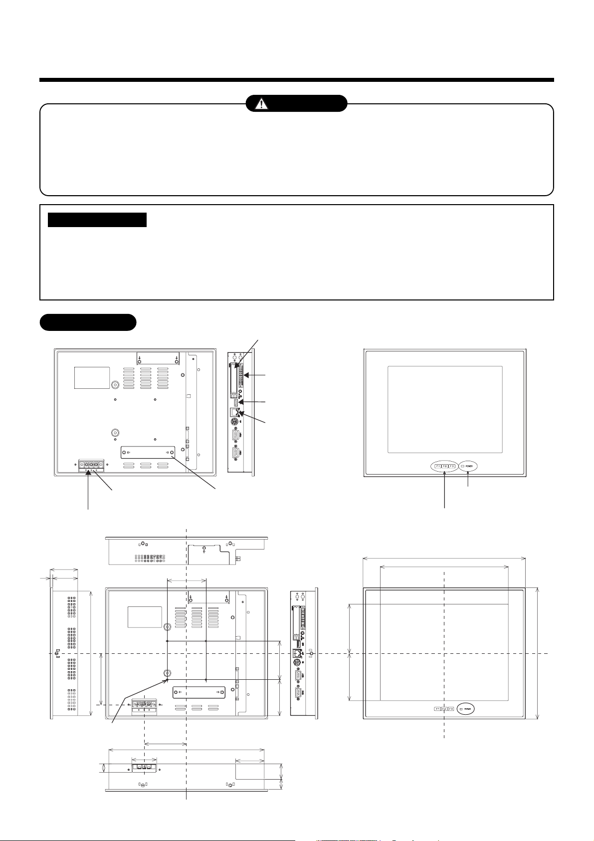
External View
249
95.7591.75
256
19 30
16
54
549
242
99.3
75
82.5
302
55.5
48
70 75
316
Function switch (F1, F2, F3)
PCI expansion unit
connector cover
Power input
terminal block
Power cable
Ethernet port
Intelligent
Server
USB mouse
CF (Compact Flash)
card slot (CF card for
data files)
POWER LED
M4 Tap (×4 pcs.)
(depth: 10 mm max.)
unit: mm
Universal Input/
Output port
4
5
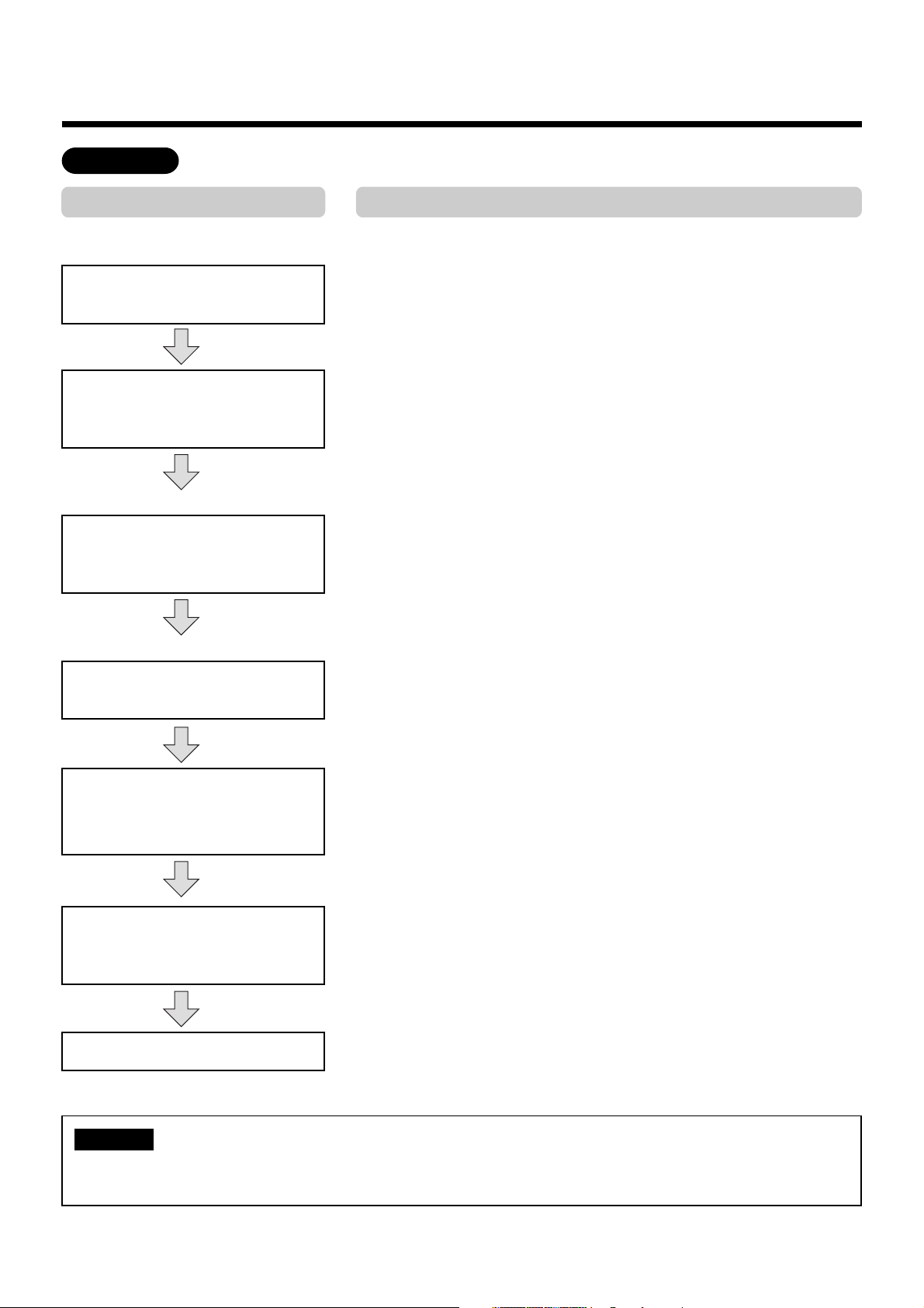
Points for Installation Work
Work flow
Process
Determination of installation
condition
(Before work)
Point
• Clarify work categories.
• Determine items of detail control.
• Determine the installation position of the Touch Screen Controller.
• Create a control wiring diagram (see page 9).
• Create an address table for each block, tenant, and area (see
page 10, 11).
• Create a schedule table for each R.C. group/indoor name (see
page 12).
• Enter block/tenant/area names in each address table (see
page 11).
• Enter schedules in each schedule table (see page 12).
• Make connections according to the control wiring diagram (see
page 9).
• Intelligent Server (see APPENDIX page 6)
• TCS-NET Relay Interface (see APPENDIX page 7)
• Indoor unit (see APPENDIX page 8-15)
• Checking according to the Before-Trial Operation Check list
(page 10) using the control wiring diagram.
• Operate the indoor unit for each system according to the control
wiring diagram.
Check that there is no incorrect wiring or piping, and then create
a trial operation check list (page 16).
• Give operational explanation in an easy-to-understand manner.
Document creation
(Data input before work)
Enter block/tenant/area names.
Enter schedules for each
R.C. group/indoor name.
(Before installation)
Electrical work
(power/control lines)
Operation mode/address settings
Trial operation and adjustments
Owner’s manual, delivery
For installation, wiring or adjustment of the accessible components for the Touch Screen Controller,
refer to the manual “A04-016”.
NOTE
5
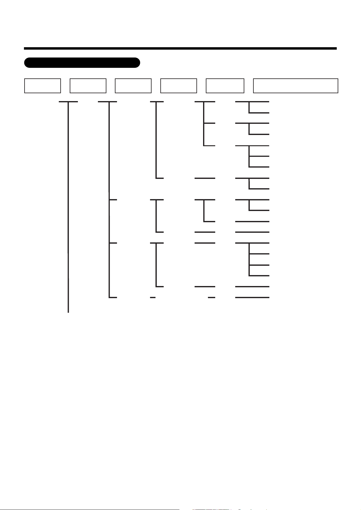
5
Points for Installation Work (continued)
All Block Tenant Area
RC
Group/Unit
Indoor Unit
(line address + indoor unit address)
Building A 1-1 (header unit)
1-2 (follower unit)
1-3 (header unit)
1-4 (follower unit)
1-5 (header unit)
1-6 (follower unit)
1-7 (follower unit)
1-8 (header unit)
1-9 (follower unit)
2-1 (header unit)
2-2 (follower unit)
2-3 (header unit)
2-4 (header unit)
2-5 (header unit)
2-6 (follower unit)
2-7 (follower unit)
2-8 (follower unit)
2-9 (follower unit)
3-1 (header unit)
1F
101
102
103
104
105
106
107
108
109
110
Shop A
Office A
Shop B
Office B
Shop C
Office C
Tenant A
Tenant B
Tenant C
Shared
space
1F outdoor
air conditioner
Management zone categories
6
6
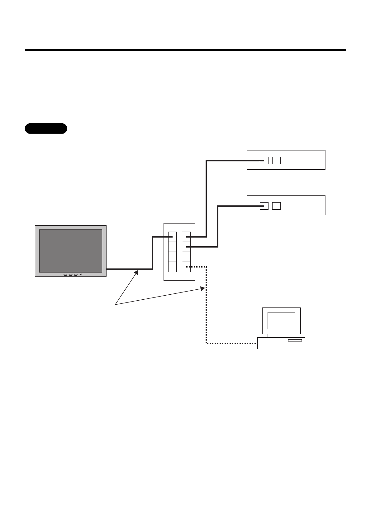
Connecting the Network wires
Connect the Touch Screen Controller to Intelligent Servers and to an optional PC for creating monthly
reports using network wires (category 5UTP straight wire), via a Switching HUB (procured on site).
• Connect the Ethernet port of the controller to a port of the HUB with a network wire.
• Connect the Ethernet port 1 of the Intelligent Server to a port of the HUB with a network wire.
• Connect the PC’s Ethernet port to a port of the HUB with a network wire. (Not required if there is not
need to create reports.)
Ethernet
PC for creating monthly reports
Touch Screen Controller
Switching HUB
Intelligent Server No.1
Intelligent Server No.2
Network wires
(category 5UTP straight wire)
Ethernet port 1
Ethernet port 2
Ethernet port
7
7
Connecting the Power cable
Connect a proper input AC voltage to the power input terminal block. Failure to do so may cause a
failure.
CAUTION
Power cable is not supplied for the Touch Screen Controller. Prepare a 3-pin power cable conforming
to applicable safety standards. Be sure to connect the earth line each of the power cable securely.
REQUIREMENT
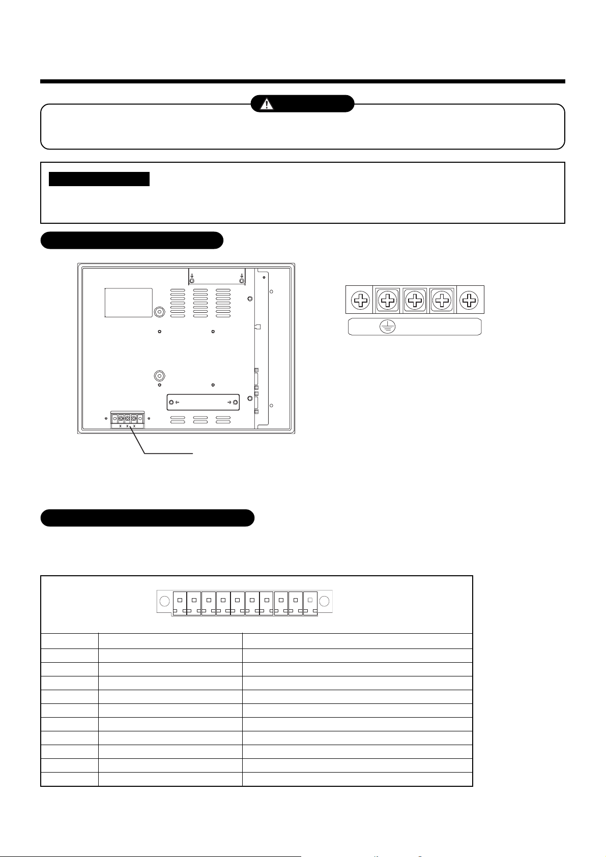
Power Input Terminal Block
Power input terminal block
For M3.5 screws
Terminal pitch: 8.9 mm
Rated input voltage: 100 to 240 VAC
■■
■■
■ Power Input Terminal Block
N
L
Universal Input/Output Port (I/O)
1
2
3
4
5
6
7
8
9
10
Pin No. Signal name
PI_PCOM
PI(0)
PI(1)
PI(2)
P_PO(0)
N_PO(0)
P_PO(1)
N_PO(1)
P_PO(2)
N_PO(2)
This port is provided with electrically-insulated 3 inputs and 3 outputs for universal use.
■ ■
■ ■
■ Universal Input/Output port connector
Universal input plus common
Universal input 0
Universal input 1
Universal input 2
Universal output 0+
Universal output 0-
Universal output 1+
Universal output 1-
Universal output 2+
Universal output 2-
Remarks
↓ Front (LCD side)
10 1
Connector: MC1,5/10-GF-3,5(PHOENIX CONTACT)
Cable connector: MC1,5/10-STF-3,5(PHOENIX CONTACT)
8
■■
■■
■ Specifications
[Input]
Input system : Current-driven input insulated by photo-coupler
Input resistance : 3 k ohms
Number of input signals : 3
External circuit power voltage : 12 to 24 V DC (±10%)
[Output]
Output system : Open-collector output insulated by photo-coupler
Output rating : 30 V DC, 100 mA maximum
Number of output signals : 3
■■
■■
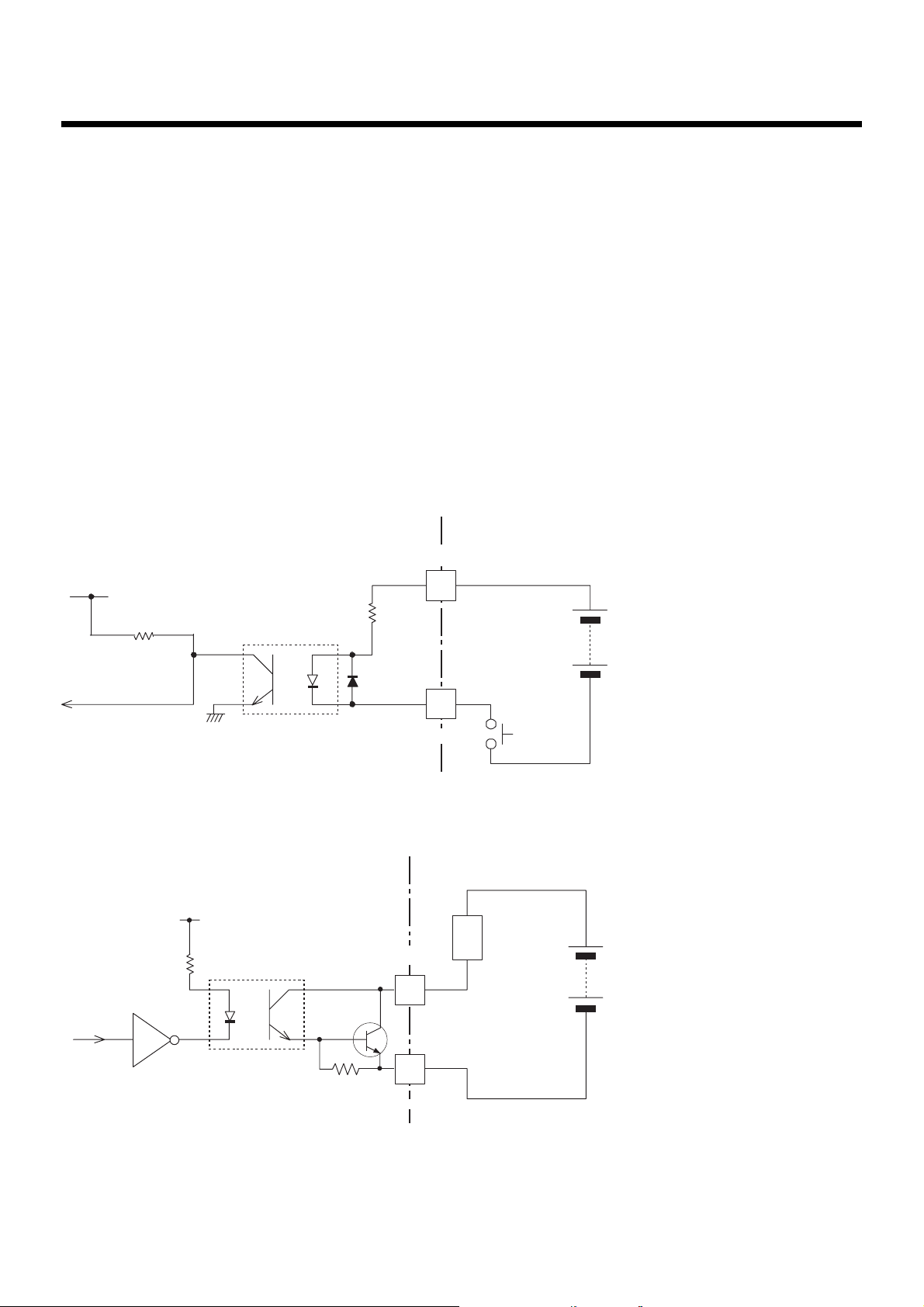
■ External Input/Output circuit
(1) Input circuit
10 k ohm
3 k ohm
1/2 W
PI_PCOM
PI(0) - PI(2)
Input/Output
connector
Input
contact
External power supply
(12 V - 24 V DC)
(2) Output circuit
330 ohm
load
(External circuit)
N_PO(0) - N_PO(2)
Input/Output
connector
External power supply
(Max. 30 V DC)
PC357
4.7 k ohm
P_PO(0) - P_PO(2)
2SD780A
9
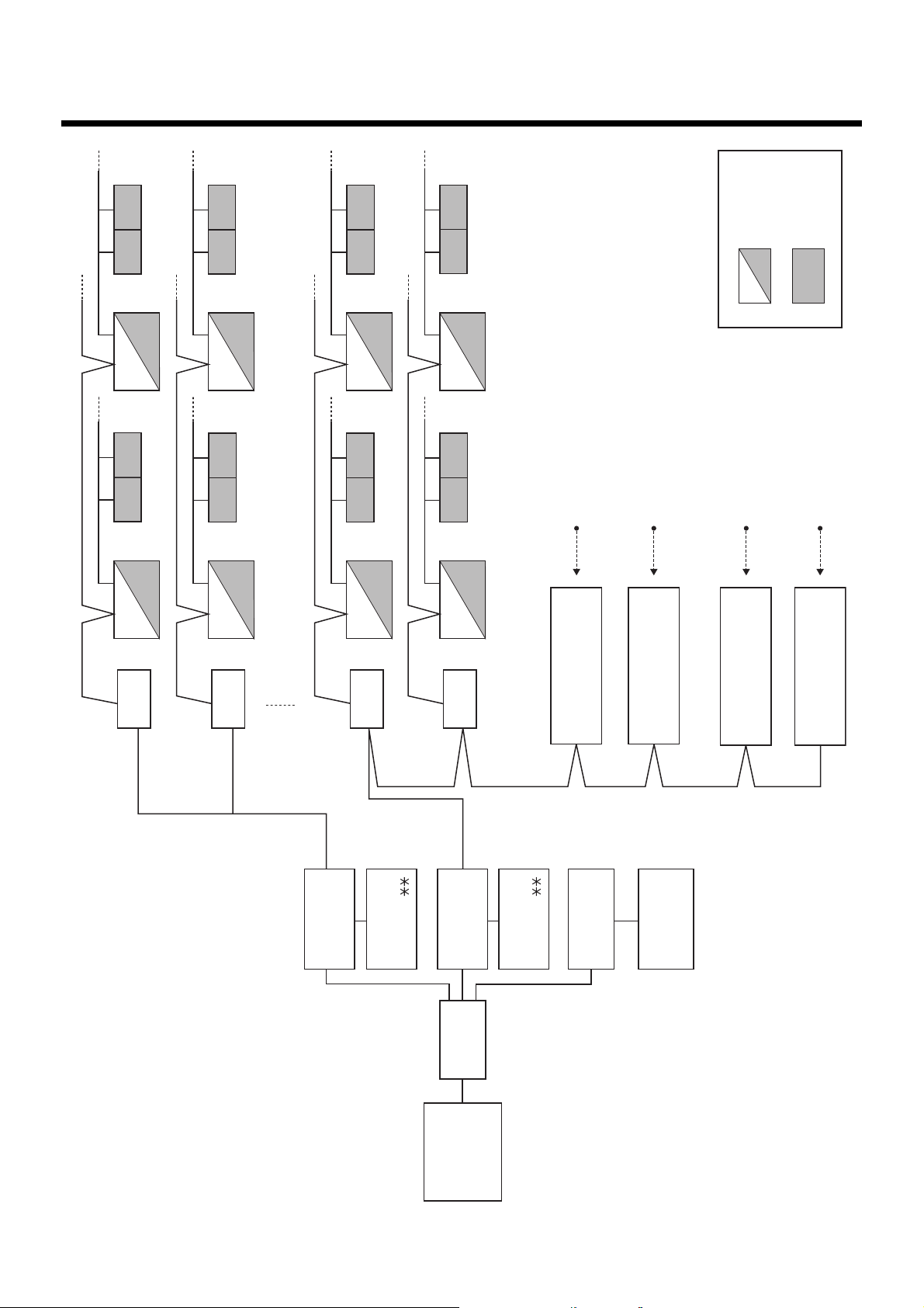
Control Wiring Diagram
8
(Connection example)
U1,U2 U1,U2 U1,U2 U1,U2
U1,U2 U1,U2
U1,U2 U1,U2
U1,U2
U1,U2
U1,U2 U1,U2
U1,U2
U1,U2
U1,U2
U1,U2
U3,U4
U3,U4
U3,U4
U3,U4
U3,U4
U3,U4
U3,U4
U3,U4
16th floor
Touch Screen
Controller
Switching
HUB
8 door-lock control signal inputs
8 fire alarm inputs
8 power meter inputs
1st-8th
floor
9th-16th
floor
1st floor
2nd floor
15th floor
Digital Input/Output
Relay Interface
BMS-IFDD01E
Energy Monitoring
Relay Interface
BMS-IFWH3E
Energy Monitoring
Relay Interface
BMS-IFWH3E
Intelligent
Server
BMS-LSV2E
PC for creating
monthly reports
Printer
Main Bus
TCS-NET Relay Interface
TCS-NET Relay Interface
TCS-NET Relay Interface
TCS-NET Relay Interface
Outdoor unit
Indoor unit
Digital Input/Output
Relay Interface
BMS-IFDD01E
BMS-
IFLSV1E
Intelligent server
software
BMS-STCC
Intelligent
Server
BMS-LSV2E
Intelligent server
software
BMS-STCC
BMS-
IFLSV1E
BMS-
IFLSV1E
BMS-
IFLSV1E
8 power meter inputs
10
Air conditioner Address Table
9
and Before-Trial Operation Check list: ( )
• Building name:
Key input
No.
Device Energy Monitoring
and Input/Output data
Power
meter No.
1
2
3
4
5
6
7
8
9
10
11
12
15
16
17
18
19
20
Outdoor
refrigerant
Outdoor unit
model name
R.C. group/
unit
name
Indoor unit
model name
Header
unit
Air Conditioner List
Block
name
Tenant
name
Area
name
Display name
Refrigerant line address
Indoor unit address
Group address
Intelligent Server address
TCS-NET relay I/F address
Fire alarm
No.
Address Information
11
Address Information
Air conditioner Address Table and Before-Trial
Operation Check list (Example)
• Building name:
Key input
No.
1
1
1
1
1
1
1
1
1
1
1
1
1
1
1
1
1
2
2
2
Device Energy Monitoring
and Input/Output data
Power
meter No.
1
1
1
1
1
1
1
1
1
2
2
2
2
2
2
2
2
3
3
3
Outdoor unit
model name
MMY-AP1401HT8
MMY-AP1401HT8
MMY-AP1401HT8
R.C. group/
unit
name
PAC-B1 • IF-1
PAC-B1 • IF-1
PAC-B1 • IF-1
PAC-B1 • IF-1
PAC-B1 • IF-1
PAC-B1 • IF-2
PAC-B1 • IF-3
PAC-B1 • IF-4
PAC-B1 • IF-5
PAC-B1 • IF-1
PAC-M • IF-2
PAC-M • IF-3
PAC-M • IF-4
PAC-M • IF-5
PAC-M • IF-6
PAC-M • IF-7
PAC-M • IF-8
PAC-S • 2F-1
PAC-S • 2F-2
Indoor unit
model name
MMU-AP0091H
MMU-AP0091H
MMU-AP0091H
MMU-AP0091H
MMU-AP0091H
MMK-AP0091H
MMK-AP0091H
MMK-AP0091H
MMK-AP0091H
MMK-AP0091H
MMK-AP0091H
MMK-AP0091H
MMK-AP0091H
MMK-AP0091H
MMK-AP0091H
MMK-AP0091H
MMK-AP0091H
MMK-AP0091H
MMK-AP0091H
MMK-AP0091H
Header
unit
1
0
0
0
0
1
1
1
1
1
1
1
1
1
1
1
1
1
0
1
Air Conditioner List
Block
name
1F
1F
1F
1F
1F
1F
1F
1F
1F
1F
1F
1F
1F
1F
1F
1F
1F
2F
2F
2F
Tenant
name
Tenant A
Tenant A
Tenant A
Tenant A
Tenant A
Tenant B
Tenant B
Tenant B
Tenant B
Tenant C
Tenant C
Tenant C
Tenant C
Office A
Office A
Office A
Office A
Shared space
Tenant D
Area
name
Shop A
Shop A
Shop A
Shop A
Shop A
Shop B
Shop C
Shop D
Shop E
Shop F
Shop F
Shop G
Office
Office
Meeting room
Meeting room
A
B
Shop H
Display name
1
2
3
1
2
3
4
5
6
7
8
9
1
2
3
4
5
6
7
8
1
2
3
1
2
2
2
2
0
0
0
0
0
0
0
0
0
0
0
0
1
2
0
1
1
1
1
1
1
Refrigerant line address
Indoor unit address
Group address
Intelligent Server address
TCS-NET relay I/F address
Fire alarm
No.
1
1
1
1
1
1
1
1
1
1
1
1
1
1
1
1
1
2
2
2
1
2
3
4
5
6
7
8
9
10
11
12
13
14
15
16
17
18
19
20
Outdoor
refrigerant
PAC-B1
PAC-M
PAC-S
 Loading...