


 SERVICE MANUAL
LCD Color Television
32HLV16 Rev.1
For Technical Bulletins, Technical Tips, or other information regarding the service of this model, visit the Toshiba America Consumer Products National Service Division website at:
www7.toshiba.com
This model is classified as a green product (*1), as indicated by the underlined serial number. This Service Manual describes replacement parts for the green product. When repairing this green product, use the part(s) described in this manual and lead-free solder (*2).
For (*1) and (*2), refer to GREEN PRODUCT PROCUREMENT and LEAD-FREE
SOLDER.
© TOSHIBA CORPORATION 2009

IMPORTANT NOTICE
WARNING: Do not modify or alter the information or data provided herein without prior written consent by Toshiba. Toshiba shall not be liable to anybody for any damages, losses, expenses or costs, if any, incurred in connection with or as a result of such modification or alteration.
THE INFORMATION OR DATA HEREIN SHALL BE PROVIDED "AS IS" WITHOUT ANY WARRANTY OF ANY KIND, EITHER EXPRESS OR IMPLIED WARRANTY OF MERCHANTABILITY AND FITNESS FOR A PARTICULAR PURPOSE.
Toshiba shall not be liable for any damages, losses, expenses or costs, if any, incurred in connection with or as a result of use of any information or data provided herein.
GREEN PRODUCT PROCUREMENT
The EC is actively promoting the WEEE & RoHS Directives that define standards for recycling and reuse of Waste Electrical and Electronic Equipment and for the Restriction of the use of certain Hazardous Substances. From July 1, 2006, the RoHS Directive will prohibit any marketing of new products containing the restricted substances.
Increasing attention is given to issues related to the global environmental. Toshiba Corporation recognizes environmental protection as a key management tasks, and is doing its utmost to enhance and improve the quality and scope of its environmental activities. In line with this, Toshiba proactively promotes Green Procurement, and seeks to purchase and use products, parts and materials that have low environmental impacts.
Green procurement of parts is not only confined to manufacture. The same green parts used in manufacture must also be used as replacement parts.
LEAD-FREE SOLDER
WARNING: This product is manufactured using lead-free solder as a part of a movement within the consumer products industry at large to be environmentally responsible. Lead-free solder must be used in the servicing and repair of this product.
The melting temperature of lead-free solder is higher than that of leaded solder by 86ºF to 104ºF (30ºC to 40ºC). Use of a soldering iron designed for lead-based solders to repair product made with lead-free solder may result in damage to the component and or PCB being soldered. Great care should be made to ensure high-quality soldering when servicing this product especially when soldering large components, through-hole pins, and on PCBs as the level of heat required to melt lead-free solder is high.
SAFETY INSTRUCTION
WARNING: Before servicing this chassis, read the "Safety Precaution" and "Product Safety Notice" instructions below.
Safety Precaution
WARNING: Servicing should not be attempted by anyone unfamiliar with the necessary precautions on this receiver. The following are the necessary precautions to be observed before servicing this chassis.
1.An isolation transformer should be connected in the power line between the receiver and the AC line before any service is performed on the receiver.
2.Always disconnect the power plug before any disassembling of the product. It may result in electrical shock.
3.When replacing a chassis in the cabinet, always be certain that all the protective devices are put back in place, such as nonmetallic control knobs, insulating covers, shields, isolation resistor-capacitor network, etc.
4.Always keep tools, product components, etc. away from children as these items may cause injury.
5.Depending on the model, use an isolation transformer or wear suitable gloves when servicing with the power on. Disconnect the power plug to avoid electrical shock when replacing parts. In some cases, alternating current is also impressed in the chassis, so electrical shock is possible if the chassis is contacted with the power on.
6.Always use the replacement parts specified for the particular model when making repairs. The parts used in products require special safety characteristics such as inflammability; voltage resistance, etc. therefore, use only replacement parts
1

that have these same characteristics. Use only the specified parts when the  mark is indicated in the circuit diagram or parts list.
7.Part mounting and wire routing should be the same as that used originally. For safety purposes, insulating materials such as isolation tubes or tape are sometimes used and printed circuit boards are sometimes mounted floating. Also make sure that wiring is routed and clamped to avoid parts that generate heat or use high voltage. Always follow the manufactures wiring routes / dressings.
8.Always ensure that all internal wirings are in accordance before re-assembling the external casing after a repair is completed. Do not allow internal wiring to be pinched by cabinets, panels, etc. Any error in reassembly or wiring can result in electrical leakage, flame, etc., and may be hazardous.
9.NEVER remodel the product in any way. Remodeling can result in improper operation, malfunction, electrical leakage, or flame, which may be hazardous.
10.Always perform an AC leakage current check on the exposed metallic parts of the cabinet such as antennas, terminals, screw heads, metal overlays, control shafts, etc. to be sure that the set is safe to operate without any danger of electrical shock before returning the set to the customer.
11.To check leakage current: (After completing the work, measure the leakage current to prevent an electrical shock.) x Plug the AC line cord directly into a 120V AC outlet. Do not use an isolation transformer for this check.
x Use an AC voltmeter having 5000 ohms per volt or more sensitivity in the following manner.
Connect a 1500 ohm 10 watt resistor, paralleled by a 0.15 µF, AC type capacitor, between a known good earth ground (water pipe, conduit, etc.) and the exposed metallic parts, one at a time. Measure the AC voltage across the combination of 1500 ohm resistor and 0.15 µF capacitor. Reverse the AC plug at the AC outlet and repeat AC voltage measurements for each exposed metallic part. Voltage measured must not exceed 0.3 volts rms. This corresponds to 0.2 milliamps AC. Any value exceeding this limit constitutes a potential shock hazard and must be corrected immediately.
Product Safety Notice
Many electrical and mechanical parts in this chassis have special safety-related characteristics. These characteristics are often overlooked in a visual inspection. The protection afforded by them cannot necessarily be obtained by using replacement components rated for higher voltage, wattage, etc. Replacement parts which have these special safety characteristics are identified in this manual and its supplements. Electrical components having such features are identified by the international hazard symbols on the schematic diagram and the parts list. Before replacing any of these components, read the parts list in this manual carefully. The use of substitute replacement parts which do not have the same safety as specified in the parts list may create electrical shock, fire, or other hazards.
SAFETY INSTRUCTION
WARNING: The metal edges of the LCD module are sharp, handle it with care.
The LCD module can easily be damaged during disassembly or reassembly; therefore, always observe the following precautions when handling the module.
1.In the event that the screen is damaged or the liquid crystal (fluid) leaks, do not breathe in, drink, or touch this fluid. Such actions could cause toxicity or skin irritation. If this fluid should enter the mouth, rinse the mouth thoroughly with water. If the
2

fluid should contact the skin or clothing, wipe off with alcohol, etc., and rinse thoroughly with water. If the fluid should enter the eyes, immediately rinse the eyes thoroughly with running water.
2.When attaching the LCD module to the LCD cover, position it appropriately and fasten at the position where the display can be viewed most conveniently.
3.Carefully align the holes at all four corners of the LCD module with the corresponding holes in the LCD cover and fasten with screws. Do not strongly push on the module because any impact can adversely affect the performance. Also use caution when handling the polarized screen because it can easily be damaged.
4.If the panel surface becomes soiled, wipe with cotton or a soft cloth. If this does not remove the soiling, breathe on the surface and then wipe again. If the panel surface is extremely soiled, wipe the panel surface with CRT cleaner sprayed onto the cloth. Do not spray the cleaner on the panel. Pay attention not to scratch the panel surface.
5.Leaving water or other fluids on the panel for an extended period of time can result in discoloration or stripes. Immediately remove any type of fluid from the screen.
6.Glass is used in the panel construction. Damage can occur if dropped or struck with hard objects.
3

7.CMOS-LSI circuitry is used in the LCD module, so avoid damage due to static electricity. When handling the module, use a wrist ground or anchor ground.
8.Do not expose the LCD module to direct sunlight or strong ultraviolet rays for extended periods.
9.Do not store the LCD module below the temperature conditions described in the specifications. Doing so could result in freezing of the liquid crystal, loss of resilience, or other damage.
10. Do not disassemble the LCD module. Such actions could result in improper operation.
11.When transporting the LCD module, do not use packing containing epoxy resin (amine) or silicon resin (alcohol or oxim). The gas generated by these materials can cause loss of polarity.
4
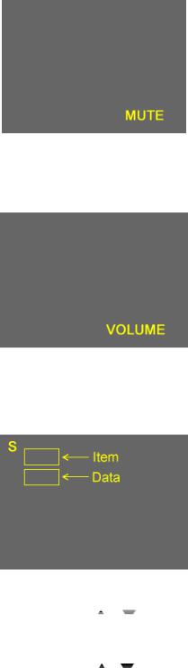
Entering Service Mode
1. Set VOLUME to minimum and press MUTE button twice on the remote control.
Ļ
2.Press MUTE button again and hold button down.
Ļ
Service Mode display
3.While holding the MUTE button, press MENU button on TV set.
Selecting the Adjusting Item
Every pressing of CH  or
or  button in the service mode changes the adjustment items.
Adjusting the Data
Pressing of VOLUME  or
or  button will change the value of data in the range from 00H to FFH. The variable range depends on the adjusting item.
Exiting Service Mode
Press the POWER button once to turn off the TV.
5

LED STATUS INDICATIONS
______________________________________________________________________________
2007 Toshiba America Consumer Products, LLC. |
Page 12 of 13 |
SMART2006002_Version1.1
6

Troubleshooting Flowchart 2006 LCD |
V1.0 |
|
|
“TV Does Not Power On” |
|
Wont Turn ON
3.3v on Pin 7 |
|
|
|
|
|
|
|
|
|
|
5v on Pin 4 of |
|
|
|
|
|
|
|
|
|
|
18v on Pin 13 of |
||||||||||||
|
|
|
No |
|
|
|
|
|
No |
|
|
|
||||||||||||||||||||||
of CN49A |
|
|
|
|
|
|
|
CN49A |
|
|
|
|
|
P803B |
||||||||||||||||||||
|
|
|
|
|
|
|
|
|
|
|
|
|
|
|
|
|
|
|
||||||||||||||||
|
|
|
|
|
|
|
|
|
|
|
|
|
|
|
|
|
|
|
|
|
|
|
|
|
|
|
|
|
|
|
|
|
|
|
|
|
|
|
|
|
|
|
|
|
|
|
|
|
|
|
|
|
|
|
|
|
|
|
|
|
|
|
|
|
|
|
|
|
|
|
|
|
|
|
|
|
|
|
|
|
|
|
|
|
|
|
|
|
|
|
|
|
|
|
|
|
|
|
|
|
|
|
|
|
|
Yes |
|
|
|
|
|
|
|
|
|
|
|
|
|
|
|
|
|
|
|
|
|
|
|
|
|
|
|
|
|
|
|
|
|
|
|
|
|
|
|
|
|
|
|
|
|
|
|
|
Yes |
|
|
|
|
|
|
|
|
|
|
|
|
Yes |
|
|||||
3.0 V on Pin 5 |
|
|
|
|
|
|
|
|
|
|
|
|
|
|
|
|
|
|||||||||||||||||
|
|
|
|
|
|
|
|
|
|
|
|
|
|
|
|
|
|
|
|
|
|
|
|
|
|
|
|
|
|
|
||||
|
|
|
|
|
|
|
|
|
|
Replace AV/ |
|
|
|
|
|
|
|
|
|
Replace Low B |
||||||||||||||
of P812A |
|
|
|
|
|
|
|
|
|
|
|
|
|
|
|
|
|
|
|
|||||||||||||||
|
|
|
|
|
|
|
|
|
|
Terminal PCB |
|
|
|
|
|
|
|
|
|
PCB |
||||||||||||||
|
|
|
|
|
|
|
|
|
|
|
|
|
|
|
|
|
|
|
|
|
|
|
||||||||||||
|
|
|
|
|
|
|
|
|
|
|
|
|
|
|
|
|
|
|
|
|
|
|
|
|
|
|
|
|
|
|
|
|
||
|
|
|
|
|
|
|
|
|
|
|
|
|
|
|
|
|
|
|
|
|
|
|
|
|
|
|
|
|
|
|
|
|
|
|
|
Yes |
|
|
|
|
|
|
|
|
|
|
|
|
|
|
|
|
|
|
|
|
|
|
|
|
|
|
|
|
|
|
|
|
|
Yellow LED |
|
|
|
|
|
|
|
|
|
|
3.3v on Pin 10 |
|
|
|
|
|
|
|
|
|
0v at Pin 1 of |
|||||||||||||
|
|
No |
|
|
|
|
|
of P812A at Power |
|
|
|
No |
|
|
|
CN42A at Power |
||||||||||||||||||
Flashing |
|
|
|
|
|
|
|
|
|
|
|
|
|
|||||||||||||||||||||
|
|
|
|
|
|
|
|
|
|
Press |
|
|
|
|
|
|
|
|
|
Press? |
||||||||||||||
|
|
|
|
|
|
|
|
|
|
|
|
|
|
|
|
|
|
|
|
|
|
|
||||||||||||
|
|
|
|
|
|
|
|
|
|
|
|
|
|
|
|
|
|
|
|
|
|
|
|
|
|
|
|
|
|
|
|
|
|
|
|
|
|
|
|
|
|
|
|
|
|
|
|
|
|
|
|
|
|
|
|
|
|
|
|
|
|
|
|
|
|
|
|
|
|
|
|
|
|
|
|
|
|
|
|
|
|
|
|
|
|
|
|
|
|
|
|
|
|
|
|
|
|
|
|
|
|
|
|
|
|
|
|
|
|
|
|
|
|
|
|
|
|
|
|
Yes |
|
|
|
|
|
|
|
|
|
|
|
|
|
|
No |
|
|
||
|
|
|
|
|
|
|
|
|
|
|
|
|
|
|
|
|
|
|
|
|
|
|
|
|
|
|
|
|
|
|
|
|
|
|
|
Yes |
|
|
|
|
|
|
|
|
|
|
|
|
|
|
|
|
|
|
|
|
|
|
|
|
|
|
|
|
|
|
|
|
|
|
|
|
|
|
|
|
|
|
|
|
|
|
|
Replace Power |
|
|
|
|
|
|
|
|
|
Check Keyboard |
||||||||||
|
|
|
|
|
|
|
|
|
|
|
|
|
|
|
Unit |
|
|
|
|
|
|
|
|
|
||||||||||
|
|
|
|
|
|
|
|
|
|
|
|
|
|
|
|
|
|
|
|
|
|
|
|
|
|
|
|
|
|
|||||
|
|
|
|
|
|
|
|
|
|
|
|
|
|
|
|
|
|
|
|
|
|
|
|
|
|
|
|
|
|
|
|
|
||
3.3v on Pin |
|
|
|
|
|
|
|
|
|
|
3.3v on Pin 8 |
|
|
|
|
|
|
|
|
|
|
Replace AV/ |
||||||||||||
8,9,11 of |
|
|
|
|
No |
|
|
|
|
|
|
No |
|
|
||||||||||||||||||||
|
|
|
|
|
|
of P812A |
|
|
|
|
|
|
Terminal PCB |
|||||||||||||||||||||
CN90A |
|
|
|
|
|
|
|
|
|
|
|
|
|
|
|
|
|
|
|
|||||||||||||||
|
|
|
|
|
|
|
|
|
|
|
|
|
|
|
|
|
|
|
|
|
|
|
|
|
|
|
|
|
|
|
||||
|
|
|
|
|
|
|
|
|
|
|
|
|
|
|
|
|
|
|
|
|
|
|
|
|
|
|
|
|
|
|
|
|
|
|
|
|
|
|
|
|
|
|
|
|
|
|
|
|
|
|
|
|
|
|
|
|
|
|
|
|
|
|
|
|
|
|
|
||
|
|
|
|
|
|
|
|
|
|
|
|
|
|
|
Yes |
|
|
|
|
|
|
|
|
|
|
|
|
|
|
|
|
|||
|
|
|
|
|
|
|
|
|
|
|
|
|
|
|
|
|
|
|
|
|
|
|
|
|
|
|
|
|
|
|
|
|
|
|
No
Check FE75 and
Power Unit
Yes
Replace AV/
Terminal PCB
Replace Seine/ |
Replace Low B |
P812A |
|
|
|
P804 |
|
|
|||
CN90A |
|
|
|
||||||||
|
|
|
|||||||||
Digital PCB |
PCB |
|
|
|
|
P803B |
|||||
|
|
|
|
|
|
||||||
|
|
|
|
|
|
|
|
|
|
|
|
|
|
|
|
|
|
|
|
|
|
|
|
|
|
|
LowB PCB |
|
|
|
|
|
|
|
|
|
|
|
|
|
|
|
|
|
|
|
|
|
|
|
|
|
|
|
|
|
|
CN61 |
|
|
|
|
|
|
|
|
|
|
|
|
|
|
|
|
|
|
|
|
Power PCB |
|
|
||
P811B
TP12
CN49A
AV Terminal PCB
|
|
|
CN81 |
D-Tuner |
|
Seine PCB |
|
PCB |
|
|
|
|
|
||
|
|
|
|
______________________________________________________________________________
2007 Toshiba America Consumer Products, LLC. |
Page 5 of 13 |
SMART2006002_Version1.1
7
 Loading...