

Page 1
Product Support
(Do Not Remove From Department)
METRICK
RC-29 SAILPLANE INSTRUCTIONS
INTRODUCTION
There is no question, two-meter sailplanes have arrived
in the mainstream of the modeling community and show
every sign of remaining for a long time. The reasons why
are many and varied but the fact that they are easier to
build and still provide every bit the flyability of the larger
Standard Class and Open Class sailplanes should not be
overlooked. Until quite recently, the designs available,
either in kit or plan form, have generally reflected the
"floater" approach, with emphasis on very light con-
struction yielding exceedingly low wing-loadings. Airfoils on these aircraft have usually been variations on the
ever-present Clark-Y The models themselves have been
typified by a kind of back-to-basics look as opposed to the
considerable design work showing-up in the Standard
and Open classes. While these "first generation"-type
two-meter designs filled the initial need, competition has
begun to disclose the drawbacks to lightly loaded and
constructed models especially those using airfoils which
TOP FLITE MODELS INC:
1901 NORTH NARRAGANSETT AVENUE • CHICAGO, ILLINOIS 60639
do not provide penetration in anything less than no-wind
conditions. It was inevitable that designers would begin
to explore the sophistication of two-meter sailplanes and
their resultant designs are now beginning to show-up on
flying fields. These designs are now being referred to as
"second generation." Your Top Flite METRICK two-meter
sailplane definitely falls into this category.
The METRICK is the fulfillment of several important
design criteria that we felt a second-generation twometer sailplane should possess:
1. The ability to be flown in a wide variety of wind
conditions and yet remain competitive by virtue of
airfoil efficiency and relatively clean aerodynamics.
2. Airframe strength to survive and even take advantage
of high-velocity 12-volt winch launches.
3. Expandability to allow the use of spoilers, releasable
Page 2

and captive towhook systems and room for reasonable ballasting as desired by the pilot.
4. The ability to accept and use today's radio equipment
including the standard configuration 500 mah battery
pack.
5. An overall appearance that is as pleasant to look at as
it is efficient.
In our opinion, the METRICK not only has met these
criteria but in actual practice has exceeded them. In
contest situations the METRICK has been launched with a
12 volt winch into 15mph+ winds, penetrated forward
from launch about 1/4 mile and completed the 10-minute
task with a high 90's spot landing—all of this in a 31
ounce, unballasted condition! It is interesting to point out
that in this particular contest, all other 2-meter designs,
and many Standard class entries either folded their wings
on tow or were blown so far back off of launch that they
were forced to land well down-wind of the landing site.
Since very few of us have anything to say about the
weather conditions that a given contest is going to have,
the METRICK had to handle the worst and still come out
on top. What about light or no-wind conditions? Your
METRICK will really come into its' own on these types of
days! The design has a longer than usual tail-moment
which dampens the usual low-speed porpoising tendencies associated with newer second generation two-meter
sailplanes.Stalls, the nemesis of
up much hard gained altitude, are very shallow with the
METRICK. The glide in these light conditions is nothing
short of incredible. The airfoil used on the METRICK
allows you to cover so much sky with such a minimal loss
of altitude you will no longer have many excuses for
missing thermals! When the nose is trimmed slightly
down the design will accelerate rapidly with a very flat
glide rate, getting you from point A to B faster than you
can believe at virtually the same altitude you started at.
The METRICK can be launched using any one of the
commercially available hi-start systems as well as 6 or 12
volt winches. The design also slope soars beautifully and
has an .049 engine set-up shown on the plans. You will
find, no matter what configuration you set the airplane
up with—engine or unpowered—your METRICK has
hands-off performance, making it an excellent choice for
a first R/C ship and an equally smart choice if competition
is your goal.
sail
planes since they
eat
PRE-CONSTRUCTION NOTES
The METRICK, like other Top Flite kits employs the use of
die-cut wood to ease the task of construction, parts fit and
identification. The dies used for this kit have been rigorously checked for absolute accuracy and should provide
you with excellent fit. Die-cut parts should be carefully
removed from their sheets by first lightly sanding the
back of each sheet of parts and then carefully removing
each part. Use a light garnet paper for the sanding and
keep a sharp hobby knife with an X-acto #11 blade or
equivalent handy for assistance in removing any parts
that might not have been completely cut-through on the
dies. Parts which oppose one another and must be precisely uniform—such as fuselage sides, ribs, etc...—
should be carefully "matched" after their removal from
the parts sheets. Matching is the process of holding the
opposing pieces together with either pins, tape or spot
gluing and lightly sanding the edges of the parts until
they are identical. A sanding blockwith light garnet paper
is most useful for this and other phases of construction.
Your building surface should be at least large enough to
accommodate the wing panels. This surface should be as
absolutely flat as possible and yet be able to accept pins
easily. We have found that a product such as Celotex fiber
board works quite well for this purpose. Another good
surface can be found in most well-stocked hardware
stores, this is a 2' x 4' fiber board ceiling tile—these are
quite inexpensive and can be used for several airplanes
before needing replacement.
As with most R/C kits that are constructed from wood, a
selection of tools—most of which can be found in the
average workshop—are a must to do the job correctly:
Hobby knife and sharp #11 blades
Single-edge razor blades
T-pins
Sanding blocks in assorted sizes
Sandpaper—220, 320, 400 and light garnet paper
Hand-held hobby saw, such as an X-acto
Power drill and assorted drill bits
Straight-edge, preferably metal, at least 24" long
90° triangle
Small power jig-saw such as the Moto-Saw
Tapes such as masking and cellophane.
Our METRICK's were constructed using a variety of common hobby adhesives including 5-minute epoxy, Cyanoacrylates, aliphatic resin (such as Titebond) and 1-hour
epoxy was used to secure the main wing wire tubes in the
wing roots. Since all of us have our own construction
techniques and favorite adhesives, stick with the ones
that you are familiar with and prefer. However, in certain
areas there will be callouts for certain types of adhesives
and we urge you to try not to substitute since doing so
could possibly cause problems structurally later on.
The last thing we should touch on before we begin actual
construction is the sequence in which the METRICK is
assembled. The sequence given to you in this booklet has
been proven to be the most straight-forward and provides the finished components in the order that you will
need them to progress to the next assembly phase. Try to
stick with the building order presented here to avoid
mistakes.
Spread the plans out on your work surface, cover them
with a clear plastic material, such as the backing from a
roll of Monokote or plastic food wrap and commence
construction.
2
Page 3
FUSELAGE ASSEMBLY
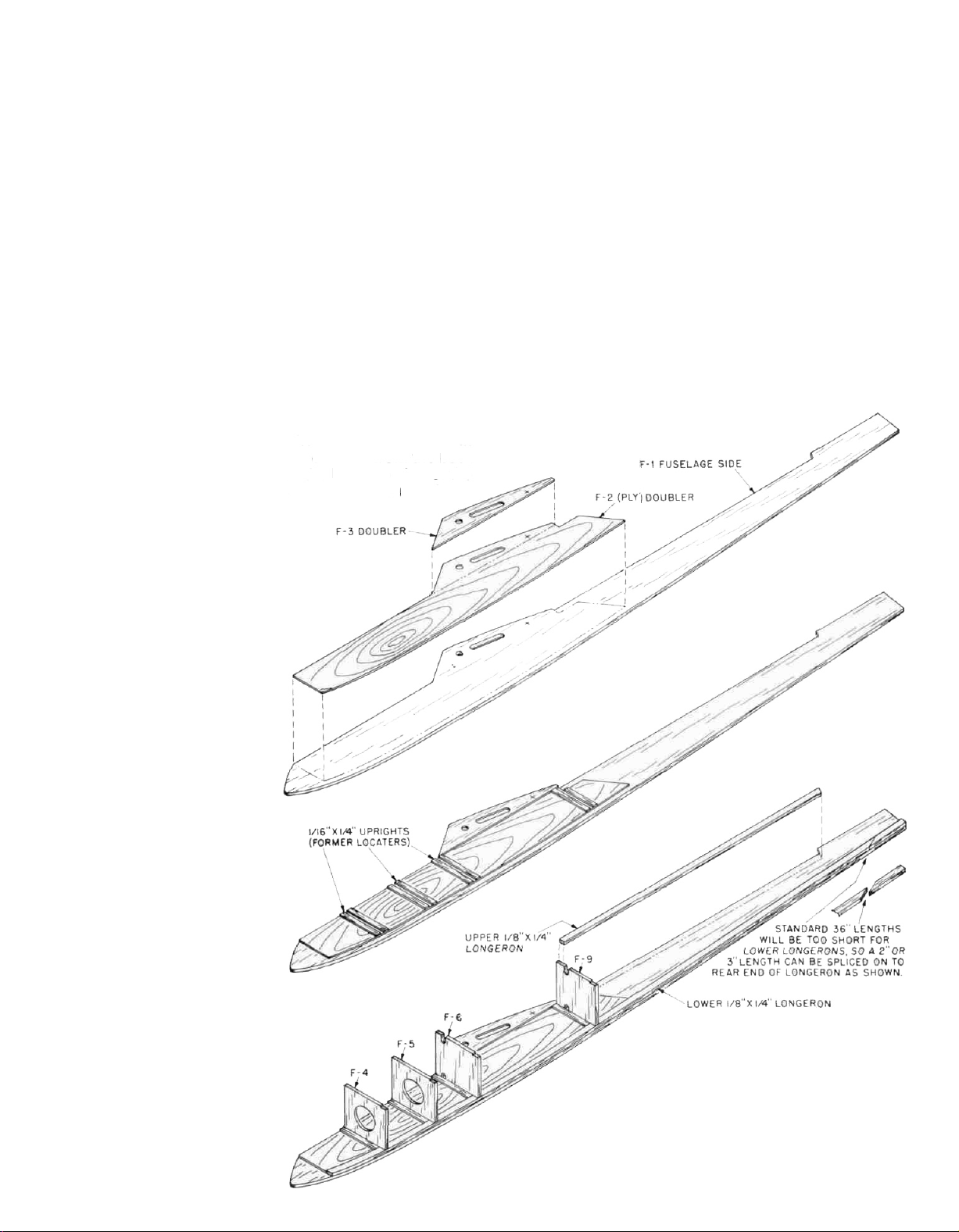
1. Remove die-cut fuselage parts; F-1, F-2 (ply) and
F-3—do this carefully and, as mentioned earlier, use
an X-acto knife to expedite this. Start construction,
by gluing (we used contact cement) the F-2 fuselage
doublers to the F-1 fuselage sides. Do this as accurately as possible, lining-up slots and holes for the
wing mating points and making sure these doublers
are flush with the top edges of the fuselage sides—
MAKE A LEFT AND RIGHT FUSELAGE SIDE.
2. Glue the 1/16" balsa F-3 doublers in place onto the
F-2's, again lining-up the slots and holes and making
sure the top fuselage side edges—allow to dry.
3. Using the 1/8" x 1/4" x 36" balsa stock supplied, glue the
bottom fuselage longerons in place, starting at the
front of the F-2 doubler, pinning and gluing as you
work aft. Note that you will need to add an additional
1-1/4"
full-length bottom longeron.
4. Cut and glue the top rear 1/8" x 1/4" balsa longerons in
place. Note that this longeron extends from the back
of the F-9 former position to the leading edge of the
fin location where it is cut on an angle to match the
fin.
of
this
longeron stock
at
the rear to complete
5. Using a sharp pencil and a straightedge, mark the
locations of all fuselage formers; F-4, F-5, F-6, F-7, F-8
and F-9, including the location of the rear 1/8" x 1/4"
fuselage uprights, behind former F-9—mark these
locations on the right fuselage side. Holding the left
fuselage side to the right, so that they are accurately
matched, transfer the former locations to the left
fuselage side.
6. Now accurately glue the 1/16" x 1/4" balsa "former
locators" in place on each side of the former F-4, F-5,
F-6 and F-9 locations. Use a scrap piece of 1/8" wood to
simulate the thickness of these formers, ensuring an
accurate slot and therefore a good fit.
7. Note the 1/8" x 1/4" balsa "nyrod spacer" at the rear of
the fuselage, directly below the leading edge of the
fin. Cut and glue one of these to each fuselage side.
to
3
Page 4

8. You will now need to drill an angled hole in the left
rear fuselage side for the red outer nyrod rudder
pushrod. Note the location of this on the plans. We
used a piece of sharpened brass tubing that was the
same diameter of the outer plastic tubing, in order to
get a good fit. Be sure to keep the location of this
pushrod as low in the fuselage as possible to avoid
any interference from the action of the stabilator
bellcrank.
9. Pin, tape or lightly spot glue the two fuselage sides
together, with their outer surfaces touching—align
them to each other very carefully. Using the sanding
block, sand their outer edges to match them identically. While the sides are still together, carefully
match the main wing tube holes and the access
slots—the main wing tube holes must line-up accurately.
10. Remove both W-1 ply wing root ribs and both F-11
fuselage root ribs carefully from their sheets.
Remove the main wing tube holes from each of the
ribs and the access slots from the F-11 ribs—use a
hobby knife to assist you. Take one of the F-11 ribs
and locate the indentation at the back, called out with
an arrow. Drill a 1/8" dia. hole in this rib, at 90° to its
surface—this rib is now your "drill guide" for the rest
of the ribs. Insert one of the main wing wire tubes
into the hole in the "drill guide" rib, letting one end of
it extend out from the rib about 1/16". Now drill the 1/8"
dia. hole needed in the remaining F-11 and W-1's, by
placing the rib onto the wing wire tube, lining up the
rib to be drilled with the "drill guide" rib and drilling
the hole—repeat this process until all four ribs have
accurately aligned and drilled holes. Use the same
procedure on the now matched fuselage sides; insert
one of the main wing wire tubes into the hole in the
fuselage side, slide an F-11 rib onto the tube and
down flat against the outside of the fuselage side,
position as shown on the plans and drill the 1/8" dia.
hole. Repeat this process with the other fuselage
side.
11. Remove ply tailskid F-12 from its sheet. Position F-12
in place on one of the fuselage sides, as shown on the
plans. Mark its forward edge location on the longeron
in pencil. With a single edge razor blade, remove
approximately 1/32" of the thickness of the longeron,
forward to the pencil mark—this becomes half of the
slot that F-12 will fit into. Do the same thing to the
other fuselage side.
12. Lay the right fuselage side on your work surface in
front of you with the inside facing you. Take one of the
servos that you plan to use and position it between
the F-5 and F-6 former locations. Note the position of
the output arm. With a pencil, mark this location on
the 1/16" x 1/4" upright former locator in front of F-6.
Remove former F-6 and F-9 from their sheets and
position them in place on the fuselage side. Mark the
location of the output arm on F-6 and mark the
location of the red outer pushrod housing, shown on
the plans, on F-9. Sand or file a 3/16" slot on each side of
these two formers so that the red outer pushrod can
fit with the formers in place.
13. Remove formers F-4, F-5, F-10 (ply), F-7 and F-8 from
their sheets. (Note that formers F-5, F-6 and F-9 are
the same width—stack them to be sure and use a
sanding block if needed to get them that way.) Glue
formers F-5, F-6 and F-9 in place on the right fuselage
side. Apply glue to the opposite edges of these formers and position the left fuselage side on them.
Tape and/or pin this structure so that it is absolutely
square and allow to dry completely.
14. With medium sandpaper, completely "rough-up"
both outer red pushrod tubes. Install the stabilator
pushrod on the
right fuselage
side by
sliding it,
from
the rear, through the slot in F-9 and then F-6, so that
about Vs" of it is exposed in front of F-6—see plans.
Slot the rear 1/8" x 1/4" upright, behind F-9, just below
the top rear longeron to accept this tube and press it
in place above the rear spacer, just below the fin. Cut
off the excess tubing exactly where shown on the
plans and use 5-minute epoxy to glue this tube in
place along the fuselage side and at F-6 and F-9.
Using the same method, install the rudder pushrod
tube along the left fuselage side. Note that this tube
gently bends downward once past F-9 so that it
arrives at the rear of the fuselage, laying along the
top of the bottom fuselage longeron and exits
through the slot we drilled earlier. Once the glue has
set, use a sharp single edge razor blade to trim off the
excess tubing on the outside rear of the left fuselage
side. Use a sanding block to sand this exit smooth
with the fuselage.
15. Glue ply former F-10 in place, directly above F-6. Note
that this former protrudes above the fuselage top by
a little more than 1/8".
16. Glue the 1/8" x 1/4" balsa cross brace in place at the
bottom of the fuselage, below F-7. This brace is the
gluing "shelf" for the 1/16" ply floor, forward to the
nose and the 1/16" cross-grain balsa floor, aft to the tail.
17. Temporarily install—do not epoxy yet—the 1/4" I.D.
main wing wire tube and the 3/32" I.D. rear fuselage
incidence tube in the appropriate holes on the fuselage sides. Install and glue in place former F-8—this
former sits immediately in front of the rear 3/32" I.D.
fuselage incidence tube. Now cut, fit and glue a
length of 1/8" x 1/4" balsa directly beneath this tube and
against the rear bottom of F-8. Temporarily install the
channeled maple "U" block in place over the main
wing wire tube, open end facing up. Install and glue
in place former F-7 so that it fits flush to the rear of the
"U" block as shown on the plans. Remove the "U"
block and both of the fuselage wing tubes.
18. Install former F-4, holding the two fuselage sides
together at the nose with tape. Check to be sure that
the structure is still "square".
19. Glue the hardwood noseblock in place. Note that this
block fits between the two balsa fuselage sides,
immediately in front of the F-2 ply fuselage doublers.
Tape the block and the fuselage sides firmly in position and allow to dry completely.
4
Page 5

20. Glue the shaped balsa forward "canopy fairing"
piece in place, on top of the fuselage directly behind
the noseblock. Use the sanding block to bring it flush
with the fuselage sides.
21. Using a piece of the 30", 1/16" balsa sheet supplied,
carefully cut and fit the canopy/hatch base. Use your
sanding block to bevel each end of this base to fit
accurately to the forward canopy fairing block and
the angled former F-10 at the rear. The base should
be sanded flush with the outside surfaces of the
fuselage sides. Remove the base and with a soft
pencil, mark the locations of formers F-4 and F-5 on
the outside top of each fuselage side. Lightly tackglue the base back in place as it will only be removed
after final fuselage sanding.
22. Bevel the bottom edges of canopy formers C-2 and
C-5 to match the required angles at the forward (C-2)
canopy fairing and the rear (C-5) angled former F-10.
Glue these two formers in place to the canopy base
also lightly tack-gluing them to their mating surfaces.
23. Glue the two remaining canopy formers, C-3 and C-2
in place on the base, using the pencil marks you
made earlier on the fuselage sides for location. Note
that these two formers are inset 1/8" from the edge of
the base on each side.
24. Using a flat work surface, glue and pin the 1/4" triangular balsa stock provided to the inside top edge of
canopy sides C-1—be sure to make a right and left
side! When dry, carefully fit the canopy sides in place,
trim as needed to get a good fit and glue and pin them
in place. When dry, sheet the top of the canopy with
cross-grain 1/8" balsa from the back face of C-2 to the
forward face of C-5. Pin and allow to dry completely.
Use your sanding block to sand the canopy/fuselage
sides flush and smooth.
25. Re-install the 1/4" I.D. main wing tube and the rear 3/32"
rear incidence tube, centering them so that equal
lengths
Apply epoxy (we used 1-hour type for this) to each
end of the maple "U" block and fill it about halfway
with epoxy also smearing some on the back face
where it will contact F-7—slide this block in place
over the tube. Make sure the tube is "buried" in glue.
Now apply epoxy to the incidence tube/F-8 joint liber-
ally, again, bury it—let these assemblies dry.
26. You must now decide whether to go with the fixed
towhook provided or with a radio-actuated captive
towhook system such as the FOURMOST RACING
PRODUCTS towhook shown on the plans as an
option. If you are opting for this captive set-up, the
installation shown on the plans works very nicely and
is quite simple. In fact, when we used this system, we
slotted the ply floor, installed the mounting rails and
secured the FOURMOST towhook in place on them
and then installed the ply floor to the fuselage.
If you are installing the stock towhook, position and
hold the 1/16" x 2" x 16" ply forward floor in place and
protrude
from each
fuselage
side (about
3/32").
mark fuselage outline in pencil. Trim-off the excess
with a hobby saw. Glue the ply floor in place, from the
center of the cross brace beneath F-7 forward and on
to the nose block—tape and allow to dry. Epoxy a
length of 1/16" x 1/2" ply—provided in an 8" length—to
the inside center of the ply floor, between the cross
brace and the back of F-6, this is the towhook plate
doubler. Determine the location of F-6 and mark its
rear edge location across the bottom of the fuselage
in light pencil. Then draw a light centerline of the
fuselage on the bottom from the F-6 line back. Measure
back
1-1/2"
and
drill a 3/32"
floor and the ply doubler. Epoxy the 2-56 blind
mounting nut provided into this hole from the inside
of the fuselage—use glue liberally around the nut's
base, without getting any into the threads.
27. Using 1/8" balsa sheet, cross grain, sheet the top of the
fuselage from the rear edge of F-7 forward to the
angled back face of F-10 and from the forward face of
F-8 to the rear edge of F-9. "Cap" the top of the two
fuselage sides between the two edges of the sheeting
with 1/8" x 1/4" balsa aligning the outer edges with the
fuselage sides. The resulting rectangular opening in
the fuselage top is for the access hatch.
28. As shown on the plans, the access hatch is a simple
frame made from 1/8" x 1/4" balsa, on edge. We used
scraps of bond paper front, back and on each side for
spacing while making this frame. As shown, install
two pieces of 1/8" x 1/4" balsa as shelves on the back
face of F-7 and the front face of F-8 to seat this hatch.
Sheet the hatch with 1/8" balsa, cross grain, lightly
sand the edges flush with the frame and lightly tack
glue the hatch in place for final sanding.
29. Glue the fuselage sides together at the rear, from the
leading edge fin position, back to the ends of the
fuselage sides at the bottom—keep glue out of the
slot you have cut in the rear longerons for F-12. Check
the fuselage carefully for equal bending and that the
top and bottom are aligned. Secure as necessary and
allow to dry.
30. Cut,
fit
and glue
bevel for fin fit. Turn the fuselage over and install
bottom 1/16" balsa cross grain sheeting from ply floor
back to point shown. Use a straight edge and a knife
to cut a 1/16" wide by 2" long slot in a piece of 1/16" balsa
sheet. This allows F-12 to slip in place. Glue this
remaining bottom sheet in place. Once everything is
dry, use a sanding block and medium grade paper to
sand the fuselage sides, top and bottom smooth. Pay
particular attention to the side-view contour at the
top of the fuselage where the 1/8" sheet meets the 1/4"
turtle deck. Sand the side and top view shapes into
the nose block but do not round any edges yet.
1/4"
balsa
turtle
dia.
hole through the ply
deck
in
place—note
5
Page 6

FIN AND BELLCRANK ASSEMBLY
1. Remove all required FIN parts from the die-cut
sheets; FIN #'s 1, 2 and 3 (two of each) and FIN #'s 4
and
5.
Also carefully remove the
ply) using an X-acto knife as needed. Sand all edges
of the bellcrank and the surface until it is completely
smooth. Note on the plans that the bottom edge of
F-1 butts to the top edge of F-2 and the top edge of F-3
butts to the bottom edge of F-2; lightly sand these
edges to create a flat, gapless fit. Remove the oblong
die-cut from FIN-2's.
2.
With a 1/8"dia.
at the top of the bellcrank for the 1/8" O.D. brass drive
tubes to be inserted—drill these holes at right angles
to the bellcrank. With a 1/16" dia. drill bit, drill-out the
two holes at the bottom of the bellcrank that will be
used for connection to the elevator servo. Lightly
sand-off any burrs.
3. Insert the forward 1/8" O.D. x 1/4" "pivot tube" and the
rear 1/8" O.D. x 1/4" "drive tube" into the holes at the
top of the bellcrank, center them so that an equal
amount of tubing is showing on each side of the
bellcrank. Making sure that these tubes are roughly
at right angles to the bellcrank, place a small amount
of Cyanoacrylate to the tube/ply joints to hold them in
place.
4. Assemble the 1/8" thick fin "core" directly over the
plans using the 1/8" x 1/2" balsa stock provided for the
leading edge and FIN #4 and 5. Glue a length of 1/16" x
1/4" balsa stock on top of the leading edge, flush with
the front edge of it.
5. On a flat work surface, make-up two fin "cover
assemblies" by edge gluing FIN #'s 1, 2 and 3
together. Holding these two assemblies together so
that they match as closely as possible, lightly sand
the leading and trailing edges with a sanding block to
get them as straight as possible and matched to oneanother.
6. Set one of the fin cover assemblies aside and glue the
other one directly to the fin core assembly, the leading edge against the 1/16" x 1/4" strip that was glued in
place earlier. Make sure this assembly is flat by pinning it to the work surface. Glue another length of
1/16" x 1/4" balsa to the trailing edge of the exposed FIN
5 core and up against the cover assembly—allow to
dry.
7. Remove the fin assembly from the worksurface and
turn it over. Glue another 1/16" x 1/4" balsa strip to the
leading edge of the core as was done on the other
side. Fit in place, pin but do not glue, the remaining
fin cover assembly. Cut and fit the remaining 1/16" x 1/4"
balsa trailing edge strip that fits immediately behind
the fin cover—glue this in place and pin. Remember,
at this point the unglued fin cover is in place but
removeable.
drill
bit,
drill-out
BELLCRANK
the
two
required holes
(3/32"
8. Slip a scrap piece of 1/8" balsa inside the fin, from the
bottom, directly under the small indention on the
FIN-2 ply part (there is an arrow pointing to this).
Using a 1/8" dia. drill bit, drill a hole all the way through
the fin—NOTE, while a drill press is most useful here
it is not necessarily needed if reasonable care is taken
to drill this hole at as close to right angles as possible.
9. Remove the unglued fin cover assembly and the
scrap 1/8" balsa. Install the bellcrank into the fin by
pressing the forward "pivot" tube into the 1/8" dia.
hole you just drilled. You will note that the rear
"drive" tube is now free to move up and down in the
oblong hole. With the fin and bellcrank flat on the
work surface, you can now glue the remaining fin
cover assembly in place with the "pivot" tube
pressed through the hole in FIN-2—allow this
assembly to dry.
10. Using the sanding block, sand the sides of the completed fin as smooth as possible. Carefully cut-out
the 1/4" FIN-6 fairing. Lay the fin assembly over the
plans in the exact position shown and glue FIN-6 in
place on the leading edge of the fin. Set this assembly
aside for final sanding.
6
Page 7

RUDDER
1. Carefully cut-out rudder parts R-1, R-3, R-4 and R-5
from the printed 1/4" balsa sheet provided. Remove
plywood die-cut part R-2 from its sheet.
2. Position the completed fin and bellcrank assembly in
place on the plans and pin. Start rudder construction
by first cutting and pinning the 1/4" x 1/2" tailpost piece
in place about 1/32" away from the trailing edge of the
fin as shown. Next, fit R-1 in place with the bottom of
it about 1/32" away from the top of the fin—if necessary, trim R-1 to fit as shown. Once satisfied with the
fit, glue R-1 in place. Remove the fin from the plans
and build the rest of the rudder as shown, pin and
allow to dry.
STABILATOR ASSEMBLY
1. Carefully remove die-cut parts E-1 (1/8" balsa), E-2
(1/16""
balsa)
and cut-out parts
E-3
from
1/4"
balsa
sheet
which is printed. Note that the outside shapes of all of
the E-1's and E-2's should be identical—carefully and
accurately stack these parts together, pin and with a
sanding block, "match" all of their edges. This procedure should produce a precise fit.
2. The stabilator halves will be built directly over the
plans and both halves will be built at the same time.
Start construction by accurately pinning E-2 in place
followed by cutting, gluing and pinning the 1/4" sq.
leading edge in place. Complete the stab outline by
cutting and gluing in place the remaining pieces of
1/4" x 1/2" balsa stock shown. Glue the 1/4" E-3 rear
gussets in place and cut the forward gussets from the
1/4" x 1/2" balsa provided and glue in place. Next, cut
and glue the
1/16"" x 1/4"
diagonal
"ribs"
in place.
3. Now glue the slotted 1/8" balsa E-1 in place directly on
top of the bottom E-2. Pin in place and allow to dry.
4.
From the
3/32" x 1/4"
ply strip provided, cut
two
3-3/32"
lengths. These will be used for the stab "cap roots."
As shown on the plans,
use a sharp pencil, a ruler
a triangle to locate the two positions for drilling the
stab roots with the two required
1/8" dia. holes. Again, when you
are drilling these holes, do so
at right angles.
and
3. Using a single edge razor blade, relieve 1/16" of the
bottom tailpost area to accept ply part R-2 on the left
side only. R-2 should be fitted to rest flush with the
top surface of the rudder assembly. Once satisfied,
glue R-2 in place.
4.
Sand the outside of the rudder to the shape shown on
the plans, followed by using the sanding block and
light sandpaper to sand each side smooth. As shown
in the drawing, bevel the leading edge of the tailpost,
where it will be hinged to the rudder, to facilitate free
left and right movement. Set the rudder aside for
final airfoiling.
5. Remove the stab halves from the plan and place one
half over the other so that they match as closely as
possible—pin together in this position and using the
sanding block, match their outlines including the
radiusing of the leading edge tips as shown on the
plans. Carefully sand the root sections flat. Unpin the
two
stab halves. Glue the
3-3/32"
ply root caps to the
stab roots, carefully matching the 1/8" dia. holes with
the tube slots in E-1—allow to dry before proceeding
to Step 6.
6. From the hardware package, remove; one (1) 3/32" dia.
x
2-5/8" wire; two (2)33/32" I.D. x 133/16" brasstubes; one (1)
3/32" x 2" wire; two (2) 3/32" I.D. x 7/8" brass tubes.
You will need to use a slower drying epoxy, such as
15-minute to have the proper amount of time to do
the job right. You are now going to epoxy the forward
13/16"
long stab pivot tubes and the rear
7/8"
long stab
drive tubes in place through the holes drilled in the
3/32" ply stab roots and into the slots in E-1. Be very
careful to not get any adhesive in the tubes themselves. As soon as both forward tubes are in place, fill
the remaining area of the slots with epoxy and level it
with your finger. Repeat this process with the rear
tubes. Note that these tubes are flush with the 3/32" ply
stab roots. Insert the forward and rear wires into one
stab half and slip the other stab onto the wire ends
and lay this whole assembly directly over the
stabilator plan and pin accurately in place with the 1/4"
gap in the center, as shown. Now glue the remaining
E-2's in place directly over the E-1's and tubes—pin
and allow to dry completely.
7. Remove the stabs from the plan and trial-fit them to
the fin and bellcrank assembly. The fit we are looking
for is firm bordering on tight—not free or loose. The
firm fit retains the stab halves in place to the fin. On
one of our prototypes we made the components so
accurately that the fit was too free and we cured this
by smearing a thin film of 5-minute epoxy on the
wires and lightly sanding them until all fits were firm.
8. Using a sanding block and light sandpaper, sand the
top and bottom of the stabs until they are quite
smooth and set them aside for final airfoil sanding.
7
Page 8

WING ASSEMBLY
Before starting this assembly sequence, you must make
the decision whether or not to build the spoiler option.
While the plans are sufficient in explaining the addition of
this option you should modify four (4) W-6 wing ribs by
relieving them to accept the 1/4" x 1" trailing edge stock,
which will be the spoilers. You will also note that the top
1/16" sheeting requirements are somewhat different and is
called out with —--— lines. Installation of the flexible
plastic dial chord housing tubes must be done before the
top, rear root section sheeting is installed. The spoiler
option shown on the plans has been used quite successfully on our prototypes and really makes the METRICK
quite "deadly" in the spot landing phase of your flights.
Note that the first phase of the wing construction is the
building of the two inboard wing sections, followed by
building and fitting the two outboard wing sections.
1. Start by removing all necessary die-cut parts from
their sheets—do this carefully, using an X-acto knife
as required. We have made a practice of stacking all
of the ribs together, in the order that they are used
and lightly sanding them to uniform shape with the
sanding block. Also be sure that the top and bottom
spar notches line-up, again using the X-acto knife if
needed. Next, prepare the 1/16" bottom leading edge
sheeting by cutting it exactly to size shown on plan—
note that unlike the top sheeting, the bottom sheet
extends from the rear of the bottom spar, forward to
the front of the 3/8" sq. leading edge. Use your metal
straight edge and knife to make the front and rear
edges straight and parallel. Pin the bottom leading
edge sheeting in place directly over the plans.
2. Cut, fit and pin the 1/16" bottom trailing edge sheet in
place over the plans. Use a pencil and a ruler to now
mark the locations of all the wing ribs—remember
that the bottom spar will cover up any marks that are
too close to the rear edge of the bottom leading edge
sheet, so make these marks further forward. Now
cut, carefully fit and glue the inboard bottom center
sheeting in place—again, use your straight edge to
achieve straight, gapless butt-joints.
3. Cut, fit and glue in place all of the bottom 1/16" x 1/4" cap
strips.
4. Cut, fit and glue the bottom 1/8" x 1/4" spruce spar in
place, lining it carefully up with the rear edge of the
bottom leading edge sheeting. Before pinning it in
place, use your straight edge to be sure it is straight
and accurately placed.
5. Use one of your W-6 "full chord" ribs as a spacer and
locate and glue the 3/8" sq. leading edge in place on
the bottom forward leading edge sheet. Be sure to
glue and pin the leading edge in place straight and
properly spaced.
6. When the leading edges have dried, remove all of the
pins from it and any you have in place back to the
spar. As shown on the plans, the bottom leading
edge sheeting, at the front has to be raised off of the
building surface by about 1/16" to conform to the
bottom forward shape of the wing ribs. As shown, we
did this by inserting some 1/16" sheet in place, deep
enough to achieve the proper curvature.
7. Glue W-7A and W-7B ribs in place at the outboard
end—note the 1/16" gap between these two ribs at the
spar to allow the installation of W-17 later on. Use a
triangle to be sure these ribs are at right angles to the
work surface. Moving inboard, glue all five W-6's in
place, again make sure they are at right angles with a
triangle.
8. Trial-fit ply brace W-14 in place—note the "to root"
arrow and the slight angle at that end. This means
that this part has to be oriented with the angled end
toward the fuselage. This part must fit onto the
bottom sheeting, against the forward face of the
bottom spar and terminate at the inboard edge of
W-2A, as shown. Glue W-14 in place making sure the
top edge of it will still accept the top spar to be
inserted later.
9. Glue the remaining forward partial ribs in place;
W-5A, W-4A, W-3A. Glue rear partial ribs W-5B and
W-4B (ply) in place.
10. Rear ply brace, W-15 is glued in place next. Like W-14,
this part has a "to root" arrow and an angle also and
must be oriented correctly. The installation of this
part is meant to create a "box" for the 1/4" I.D. brass
wing tubes. When gluing W-15 in place, use one of
these tubes as a "spacer" to ensure a good fit.
11. Glue rear partial rib W-3B in place.
12. Vs" balsa root ribs W-2A and W-2B are now glued in
place. Note that these ribs are slightly angled at the
top to match the two angles of W-14 and W-15 at the
root.
13. As shown on the plans, cut, fit and glue in place on
the rear face of the 3/8" sq. leading edge, the 1/16" x 1/4"
balsa "sheeting shelves", between each rib—see
cross-section.
8
Page 9

14. With the 1/8" balsa sheet provided, fit, cut and glue the
vertical grained "spar webs" in place between each
rib from W-4B out to W-7B. Note that these webs are
fitted flush with the forward edge of the spars and are
cut to fit between the top and bottom spars. Do this
step carefully to ensure good, positive fits.
15. Now cut, fit and glue the forward 1/16" balsa webs in
place between each rib from the inboard W-6 out to
the inboard position shown for dihedral brace W-17.
Note that the grain of these webs runs horizontal or
parallel with the span and that they are full depth
from the top of the bottom sheeting to the top of each
rib and full against the forward face of each of the 1/8"
balsa spar webs.
16. Use a small sanding block and light sandpaper to
bevel the bottom trailing edge sheeting as shown on
the plans.
17. Cut, fit and glue the top 1/16" x 7/8" trailing edge in place.
Pin and allow to dry completely.
18. Unpin and remove the two wing panels from the
work surface. Prop-up the outboard end of each
panel
1-1/8",
with
the inboard end flush
with
the edge
of your workbench. Using the sanding block, carefully sand the inboard face of wing panel so that it is
smooth and straight. This should be done accurately
to provide a flat gluing surface for ply cap ribs W-1.
Repin
wing
sections flat
to
the worksurface.
19. Glue W-1 directly to wing panel roots, carefully
lining-up the large wing tube hole in W-1 with the
space between W-14 and W-15. Be sure W-1 is also
flat against the worksurface—allow to dry.
20. Trial-fit one of the 1/4" I.D. brass wing tubes through
the large hole in W-1 and into the box between W-14
and W-15. As shown on the plans, the tube must fit
against W-4B (ply) and contact the bottom spar. This
fit imparts the correct dihedral angle when the panels
are aligned to the fuselage. Once satisfied, remove
the tube. Cap-off one end of the tube to keep epoxy
from entering it when it is permanently put in place.
We simply placed one end of the tube over a piece of
bond paper, applied Cyanoacrylate adhesive around
the joint and sanded off the excess paper, leaving a
bond paper" cap".
21. Measure, cut and fit—but do not glue—the top 1/8" x
1/4" spruce spar. Set these aside for immediate installation after the main wing tubes have been installed.
22. Mix a batch of 1-hour type epoxy and be sure to mix
enough since we are now going to fill the wing tube
box with epoxy and tubing. Pour epoxy directly into
the wing tube box to the level of the bottom of the
hole in W-1. Insert the 1/4" I.D. wing tube into the hole
and in place as described in Step 20 above. Pour
epoxy over the tube to a level at the bottom of the
wing rib spar notches. Make sure the wing tube is in
and will stay in the proper position and glue the top
spruce
wing
spar in place.
Pin
as
needed and
allow
to
dry completely.
23. Cut, fit and glue the top 1/16" balsa leading edge
sheeting in place—note that this sheeting, unlike the
bottom, extends from the back surface of the leading
edge to halfway across the top wing spar, leaving
about 1/8" of the top of the spar exposed. Pin and allow
to
dry.
24. From the 3/32" x 1/4" ply strip stock provided, make and
epoxy in place the wing eyehook screw bases, which
are epoxied to the back side of W-2B—refer to plans
for location.
25. Carefully and accurately cut and fit the two required
pieces of 1/16" balsa sheet needed for the inboard top
center section. Glue in place the forward piece of this
sheeting, leaving the remaining piece for installation
after the rear wing incidence tubes are installed. Cut,
fit and glue in place all of the top 1/16" x 1/4" cap strips.
26. Remove the panels from the worksurface. Press in
place, through the rear 1/8" dia. holes drilled earlier,
the
3/32"
I.D. x 1-3/16"
brass
incidence tubes.
Press
the
F-11 fuselage ply wing ribs in place over the protruding ends of the fuselage wing tubes. Slip the forward
1/4" dia. wing rod and the rear 3/32" dia. incidence wire
in place through the fuselage and slip the wings in
place. Line-up the trailing edge tip of the W-1 root ribs
with the F-11 fuselage ribs and tape or pin accurately
in place. Make four 1/16" ply wing incidence tube
"formers", as shown on the plan, using ply leftover
from the die-cut sheets. Epoxy one on each side of
the wing incidence tubes as shown, fill with epoxy
and allow to cure. When dry, finish sheeting the top
rear center section of each panel.
27. Remove the F-11 fuselage ribs and accurately tackglue them to the W-1 root ribs—these will be
removed after final sanding of the wings and be
installed on to the fuselage during the FINALASSEMBLY stage of these instructions.
28. The outboard wing panels are now built directly over
the plans, using the same techniques described ear-
lier in this section. Note that in the outboard wing
panels the vertical 1/8" balsa shear webs are only
installed between W-7B and W-8. Note that the 1/16"
horizontal-grained full-depth webs are only fitted
between the outboard end of ply dihedral brace W-17
and rib W-8 and between W-8 and W-9. When the
panels are complete, lightly taper the trailing-edge
facing ends of triangular gussets G-1 and G-2 and
glue them in place as shown. When the outboard
panels are complete remove them from the worksurface, prop-up the tips
at
W-13
1-1/4"
and
use a sanding
block to bevel the inboard surface of the panels to
achieve the proper polyhedral angles shown on the
plan. Take your time here and do a careful job—each
completed wing panel must carry the same polyhedral angles.
29.
The
two
13/16" x 1" x 6" balsa
wingtip
blocks are
first
rough-cut to shape, using the plans for templates
and then glued in place. Use a hobby knife to first
bring the tips down to rough shape and then use a
sanding block and sandpaper to finish the job. Note
9
Page 10

the "typical wingtip cross sections" shown on the
plan.
30. The outboard panels are now joined to the inboard
panels by first epoxying W-17 in place in the inboard
panel and then epoxying the two panels together,
proping-up
dry completely.
FINAL ASSEMBLY
1. Use your sanding block and medium-to-light sandpaper to airfoil the fin, rudder and stab halves to
shape—note cross sections on plans.
2. Thread at least 1/4" of the 1" threaded stud provided
into one end of the inner yellow pushrod and then
thread a clevis in place on the stud. Since we don't
want this clevis to have any possibility of unscrewing
itself from the stud, add a drop or two of Cyanoacrylate to the threads. Install the wing rods and wings to
the fuselage. Attach the clevis which is now con-
nected to the pushrod, to the exposed 1/16" dia. hole in
the bottom of the fin and insert the opposite end of
the yellow inner pushrod into the end of the red outer
pushrod tube at the top rear of the fuselage. Apply a
slow drying glue to the bottom of the fin, where it
rests against the lower longerons and to the sides of
the fin, where it "nests" between the fuselage sides
and carefully slip the fin in place into the rear of the
fuselage. Now mount the stab halves to the fin and
view the assembled aircraft from the front. Make sure
the fin is 90° to the fuselage and that the stab halves
are flat and alinged at right angles to the fin—take
your time to ensure everything is properly aligned.
Use pins, tape, etc... to hold the fin in the proper
position and allow to dry completely.
3. With the wings in place on the fuselage, lightly pencil
the outline of the root F-11 ply ribs onto the portion
extending forward onto the canopy sides. Then mark
the top and bottom location of the front face of
angled former F-10. Remove the wings and remove
the previously tack glued F-11 ribs from the right and
left wing roots. With a saw, using the top and bottom
the
tips, at W-13, 1-1/4"
as
shown.
Allow
31. The wing panels should now be carefully and completely sanded to final shape. Note the progression
shown on the plans for bringing the leading edge
down to final shape and the template provided for
checking the leading edge entry. Also note that as the
to
inboard sections are sanded, the tack-glued F-11 ribs
will assume the exact shape of the W-1 wing root ribs.
location marks you just made, cut off the front of the
F-11 ribs. Glue the two small forward pieces of these
ribs in place on each side of the canopy hatch, using
the outline you drew for
parts of F-11 in place over the wing tubes and to the
fuselage sides. Use a sanding block to bring any
protruding ends of the wing tubes flush with the F-11
ribs.
4. Glue ply tailskid F-12 into the slot at the bottom rear
of the fuselage. The completed fuselage is now
sanded to final shape—refer to the plans for typical
radiusing.
5. Carefully remove the previously tack glued canopy/
hatch and the access hatch from the fuselage. Using
the 1/16" x 1/2" ply strip provided, cut a length to fit
accurately between the two inside fuselage sides at
the forward base of the canopy/hatch. Epoxy this to
the bottom of the canopy base so that approximately
1/16" of its forward edge will fit beneath the front balsa
canopy fairing. This becomes the forward canopy
"hold-down". Since the canopy is held in position at
the rear when the wings are in place, all that is
needed is a simple hook made from a straight pin,
one for the bottom rear of the canopy base and one
for the floor of the fuselage, and a rubber band.
6. Locate the positions for the two wing-joining eyehooks, drill small diameter guide holes into the W-1
ribs and screw the hooks in place. A pair of pliers are
used to slightly open these hooks so that #62 rubber
bands or a spring, if you wish, can be used to join the
panels to the fuselage.
placement.
Glue the two
rear
10
Page 11

COVERING
Earlier in the introduction, we spoke of design criteria and
in the #1 statement "airfoil efficiency" and "clean aerodynamics" were mentioned. The METRICK was designed
to be a clean, relatively fast two-meter sailplane and
while the basic shapes have been provided, what the
airplane is covered with is certainly an issue. Airframe
cleanliness and full flight potential is realized by using
Monokote for this airplane. You will need two rolls of
Monokote for the METRICK, leaving some left over.
Cover each of the separate components; wings, stab
halves, rudder, canopy/hatch, access hatch and fuselage,
also cover the spoilers separately if you have built this
option. Follow the instructions provided with each roll of
Monokote. Remember, to keep it simple, light and beauti-
ful, keep it Monokote!
After covering, your spoilers and access hatch are hinged
RADIO INSTALLATION
The radio installation in your METRICK is very straightforward and therefore should not present a great many
problems. As the plans show, the design is set-up for
standard configuration 500 mah battery packs with room
left over for any ballast required to arrive at the proper
C.G. (Center of Gravity). As shown on the plans, the
battery pack should be installed in the forward-most
compartment of the fuselage, with the connector harness
facing aft. Small, custom cut pieces of foam rubber are
used to securely nest the pack in place—pack firmly, not
tight, to avoid any shifting. Remember that this compart-
ment will in all likelihood have to receive a small amount
of ballast (lead) to achieve the C.G.
The compartment directly behind the battery pack is
used for the receiver. In our METRICK's, we mounted the
receiver in place on its' side, leaving quite a bit of room on
the other side of this compartment which was used for
the switch. If your antenna is not internally mounted,
simply drill a 1/16th hole in the side or bottom of the
fuselage, route the antenna through this hole and aft back
to the rudder post area where you can secure it with a
rubber band and a small hook made from a straight pin.
The servo compartment, as shown, is directly behind the
receiver. This
rudder and stab—servos. Note that the servos shown on
the plan are reversed to one another for optimum servo
output wheel clearance. In the case of radio systems that
have a servo reversing feature, this presents no problem.
If your radio does not have this feature, then you must
first determine the direction that your servos go to
achieve the proper surface directions upon radio command. The servos must then be mounted correctly into
the fuselage. As noted earlier, the leftover piece of 3/32" x
1/4" ply strip that was used for the stabilator roots should
be used for the two required servo mounting rails. These
should be carefully cut to fit accurately between the
area
is
used to house the flight
control-
using Monokote Trim sheets with the "wet" adhesive.
Carefully slot the fin and rudder and epoxy these hinges
in place ("flex" them a few times first to free them up) on
first the rudder and then the fin—wipe off any excess glue
with acetone. Locate and install the nylon rudder horn
using the two #2 wood screws provided. Install the
towhook and secure as shown on the plans.
If your flying site isn't grass you may wish to protect the
bottom of the fuselage from "gravel rash" by the addition
of a rubber-type skid strip. A length of this material
extending from in front of the towhook forward to the
nose works quite well. This self-adhesive material can be
found in most automotive supply stores. There are also
commercially available skid strips sold in hobby shops,
Airtronics is one of the manufacturer's who make it
available.
inside fuselage sides and on top of the 1/16" x 1/4" balsa
servo rail locators that were glued in place during fuselage construction. Locate and epoxy the forward rail in
place first, as close to former F-5 as possible. Trial-fit one
of your servos in place with the forward mounting lugs
resting on the forward servo rail. Slip the rear servo rail in
place with the rear mounting lugs of the servo resting on
it. This will locate the position of the rear servo rail—mark
its location in pencil on the inside of the fuselage, on each
side, remove the servo and epoxy the remaining servo
rail in place.
While the METRICK's radio compartment was specifically designed to accept most radio systems currently
available, the servo output arms for some systems may
require some trimming or modification in order to clear
the fuselage sides during their movement cycle. Once
you are satisfied that the servos move in the proper
11
Page 12

directions for the desired control response and can sit
side-by-side with the movement of the output arms not
coming in contact with each other or the fuselage sides,
the servos can be mounted in place using small #2 x 1/2"
wood screws (not supplied). At this point, servo con-
nection with the pushrods is the next stop. First, center
the servos, using the trims on the transmitter. The servo
output arms should fit approximately 90° to the fuselage
sides to deliver equal movement. You will probably have
to drill-out the holes in the servo output arms to about
.076 dia. to accept the 3" threaded one-end studs provided for servo connection. With a razor blade, cut-off all
but 1/2" of the inner yellow nyrod pushrod that is protrud-
ing into the servo compartment. Thread at least V4" of the
threaded end of the 3" threaded stud into the inner nyrod.
We would suggest "nuetrilizing" the rudder and
stabilator first, with tape. As shown on the plans, make a
"Z"-bend at the servo-end of the stud and cut off the
remainder of the stud. The "Z"-bend can now be pushed
in place through the drilled-out hole in the servo output
arm and the output arm screwed in place on the servo.
Note that the servo plug wires are routed forward,
through the hole in former F-5 to the receiver
compartment.
With our METRICK's we chose not to mount the switch in
the typically external manner, but rather left them loose
in the receiver compartment, packed with foam rubber in
the upright position. This requires that the canopy/hatch
be lifted up, the switch activated before and after each
flight. In practice, this proved to be perfectly acceptable
and the fuselage side was spared the need for the cutting
of holes for the switch—use the method that most agrees
with you.
If you are planning on flying your METRICK with 2 channels, your radio installation is now complete and you can
move on to the PRE-FLIGHT and FLYING sections of these
instructions.
As mentioned earlier in the instructions, if you have
planned to run a third spoiler channel you should now
install this servo. The third, optional, servo installation
shown on the plans for spoiler activation is the system we
used in our prototypes and works quite well. You will
need
to
fabricate
(material not supplied) for mounting this servo beneath
the access hatch, as shown. Use Dubro #181 "Ball-Links"
(not supplied) on each side of the servo output arm for
the loops in the ends of the spoiler chords to slip over. You
two
3/32" x 1/4" x 1-5/8"
ply servo rails
can see that as the servo is actuated, by moving the
"throttle" stick or lever on the transmitter, the arm
rotates, thus pulling the individual spoiler chords,
causing the spoilers to be pulled up. As the servo is
returned to its' original setting, the rubber bands in the
spoiler bays pull the spoilers back down flush with the
wing's upper surface. It is most important that the
tension relationships are the same for both spoilers and
that they deploy at the same angles and that they return
flush with the wing panels. Valuable wing efficiency can
be lost with improperly seated and/or deployed spoilers.
Note that the travel of a standard servo is sufficient to
deploy to spoilers to about 50°-70° at full movement. This
amount of travel is more than sufficent to achieve radical
loss of lift. 90° movement of the spoilers in relationship to
the surface of the wing is not needed. Once the servo is
mounted in place to your satisfaction, route the plug
harness wire forward, through former F-6 (you will have
to cut a small, appropriate-sized hole), through the servo
compartment and through former F-5 to the receiver.
Install the wing panels to the fuselage and secure with
two #62 rubber bands between the two eyehooks, as if in
preparation for flight. The two loose, unlooped ends of
the spoiler chords should now be inside of the fuselage,
roughly lined-up with the "Ball-links" on the servo output
arm—the servo should be set at the "low spoiler setting",
in other words spoilers down. At this point, we taped the
spoilers down, flush with the wing, using making tape.
Slip a short length (about 1/4") of 3/32" I.D. brass tubing (not
supplied) over one end of the spoiler chord, wrap the
chord around the "Ball-Link" and slip the end back
through the tubing, creating a loop about 5/16" long. Pull
on the chord until the slightest resistance is felt and crimp
the tubing with a pair of pliers. We applied a small drop of
instant glue to the tubing/chord joint to complete the
connection. Repeat this process with the opposite chord,
remove the tape holding the spoilers in place and test the
action of the spoilers, using the transmitter. Remember
that in order of priority, #1 is to have the spoilers sit flush
with the upper surface of the wing when fully at rest.
Test the action of the entire radio installation to make sure
that it is bind-free and that radio commands from the
transmitter provide the correct surface movement. This
cannot be stressed enough since backward servo installations are one of the number one reasons for initial
crashes—check it and then check it again!
12
Page 13

PRE-FLIGHT
1. CENTER OF GRAVITY: Although the METRICK has a
fairly wide C.G. range intital flights should be made
with a balance point located directly at the wing spar
location, or
wing. This is the time to add any ballast required to
achieve this balance point. Ballast should be lead
sheet or lead shot and should be placed forward
and/or beneath the battery pack. The ballast should
be securely but not permanently installed in order to
make changes for personal preference in glide later
on. If you have built the engine powered option it
may be necessary to switch the locations of the
receiver and battery pack to achieve the correct C.G.
2. RADIO AND AIRFRAME INSPECTION: Once again,
check the radio system to be sure that the surfaces
move in the desired direction by radio command and
FLYING
Whether your METRICK has been set-up powered or
unpowered, you will need to perform a series of handglides to develop a basic neutral trim. Assuming that the
C.G. is right and that the radio is on and functioning, run
into the wind until the airplane begins to feel "light" at
which time throw it straight, slightly nose-down with the
wings level. The airplane should glide straight forward at
a very flat angle. Try to remember what commands you
had to give the transmitter to achieve straight and level
flight. Repeat these hand-glides until you are certain
what is required. We used our transmitter trims to
achieve the flat glide that we were looking for and then
made the required adjustments on the servos, followed
by returning the trims to neutral and repeating the process until the plane flew flat and straight with no stick
movement on the transmitter necessary. This then is
dead-neutral trim. As your flight time and familiarity with
the METRICK build-up, you can experiment with moving
the C.G. progressively aft—we caution you to do this in
very small increments—until the point is reached that
you can literally vary the cruise speed of the airplane with
transmitter trim, without stalling. This is done by removing small amounts of lead ballast from the nose until you
are satisfied.
Assuming that your METRICK is an unpowered sailplane,
the next phase is a tow-launch. Although this method of
launching a sailplane can be intimidating to the beginner,
the METRICK's stability on tow is of great help. If you are
using a "Hi-Start" system—surgical chord and monofiliment line—pull the line back until you have about 20 lbs.
of tension. Hook the tow-ring onto the towhook on the
bottom of your model. With the transmitter on and of
course the receiver, hold the airplane in your right hand,
transmitter in your left, with the wings level and the nose
at about 15° to 20° up. Launch the airplane briskly and
level. The airplane should quickly assume about a 50° to
60° climb attitude and be moving in a straight line up and
away from you. Any corrections to maintain the straight
launch should be done with small movements of the
transmitter stick—avoid quick, full-throw movements
2-5/8"
back
from the leading edge of the
that the action of the servos is bind-free. If you have
installed a captive tow-hook system, test it's opera-
tion to be absolutely sure of release on command.
Inspect the airframe and it's various components.
Check for warps in all of the surfaces. If any are found,
now is
METRICK's employed the use of about 1/4" of wingtip
wash-out (wash-out is the raising of the trailing edge
wingtip). This was used to avoid any tip-stalling tendencies that might have shown up on our prototypes.
Subsequently, our METRICK's have been flown with
and without wash-out with equally good results—
pick the set-up that works best for you. Once everything has been checked to your satisfaction, make
sure the battery pack is charged and head for the
flying site.
because at launch speeds the flight surfaces are very
effective! As the airplane comes over the top of the Hi-
Start, it will begin to slow down and the nose will be
about level with the ground. At this point, apply some
down-elevator to let the tow ring come free from the tow
hook. The airplane should now be free from the tow ring
and flying on it's own. If you followed the hand-gliding
instructions, your METRICK will very likely be very close
to trimmed for flat and level flight.
First try a series of both left and right turns to get the feel
of the rudder, be sure to trim the rudder for straight flight
on the transmitter, if necessary. Next, while at altitude,
slowly feed in up elevator until you observe the airplace
beginning to "mush", this is the beginning of a stall and
knowing where it begins and how drastic it is can save
your airplane later on. Continue to hold up elevator until
the airplace fully stalls—it will literally stop flying.
Observe carefully what it does at this point. Does it lose
all airspeed, drop the nose and continue flying or does it
fall-off on one wingtip or the other? If it falls off on a
wingtip, some washout in the wingtips could help—not
cure—this phenomenon. Practically speaking, it is best to
know the stall characteristics of your particular airplane
and to avoid those flight circumstances which will lead to
them. While we are still at some altitude, try dropping the
nose a little with a touch of down elevator to get some
idea of the speed range that your METRICK provides. As
the model's speed picks up, the airfoil becomes quite
efficient and tends to resist the nose-down condition—
the result is a very flat, fast glide rate that allows you to
cover a lot of territory with a minimal loss of altitude.
Landings, especially some of the first ones, until you are
used to the airplane, should be set-up in the normal
fashion, except for the final up-wind leg which might
have to be longer than you are used to since the
METRICK, with the nose slightly down, as in a landing
approach, tends to want to stay airborne. If you have
equipped your plane with spoilers, the landing task
becomes very easy with incremental amounts of spoiler
the
time
to
correct them. Initial flights
with
our
13
Page 14

applied at the right times. If the METRICK is your first
sailplane or your 21st, there are three rules that always
apply in soaring:
1. Practice
2. Practice
3. Practice
We are going to assume that you are now fairly comfort-
able with the airplane and would like to attempt some
thermal soaring. As the METRICK comes off of tow, we
have made it a practice to penetrate out upwind in a fairly
straight line, watching the airplane carefully for lift (or
sink) information. If the airplane flies directly into a thermal, you will notice some decrease in forward speed and
a flattening of the glide together with a flat elevator-type
climb. When you see this, make a broad turn, searching
for the "core" of the thermal, avoiding the outer edges.
Once into the center of the lift, hold the rudder and
elevator combination that provides the highest rate of
ascent and at all costs, avoid stalling. You will find that the
METRICK will outclimb most anything at the field in the
same lift conditions—its rate of climb is awesome.
If you encounter a thermal during cruise that is either to
the left or right of the airplane, you will know because the
wing encountering the lift will kick up. When this hap-
pens, turn into the direction of the wing panel that went
up—right wing up; turn right, left... same procedure
except turn left. Again, search out the core of lift and
enjoy.
If you have chosen to power your METRICK with the
optional .049 engine set-up shown on the plans, all of the
above applies to you except, of course, for the launching
technique. Your engine should be started and the needle
valve set to provide maximum RPM's. Making sure that
your receiver and transmitter are on, the airplane should
be hand-launched with the wings level and the nose
slightly down, with a brisk throw—do not heave the
model, it is not necessary and could cause a stall. Let the
model climb-out and up at a shallow angle at first to
build-up airspeed and allow the wings to become efficient. With a standard reed-valve engine and three minutes of fuel, you should have little trouble reaching 300 to
400 feet of altitude. When the engine quits you are flying a
sailplane and the information mentioned earlier applies
concerning thermal activity.
No matter how you have chosen to fly your METRICK we
sincerely hope that it has been a rewarding project for
you and thatthe hours spent on the building board will be
nothing compared to the hours of soaring enjoyment to
come.
Speaking of soaring enjoyment, TOP FLITE MODELS,
INC. is very proud to be the first model aircraft company
to provide you with information and a membership dec-
laration for the world's largest R/C sailplane organization,
the LEAGUE OF SILENT FLIGHT. Your R/C soaring activ-
ities can take on a whole new meaning and importance
by participating in the L.S.F.'s Soaring Accomplishments
Program.
INDEX
Application for LSF Membership ......................................................................... 1
Covering ............................................................................................... 11
Fin and Bellcrank Assembly ............................................................................. 6
Final Assembly ......................................................................................... 10
Flying .................................................................................................. 13
Fuselage Assembly ..................................................................................... 3
Introduction ............................................................................................ 1
Pre-construction Notes .................................................................................. 2
Pre-flight............................................................................................... 13
Radio Installation ....................................................................................... 11
Rudder................................................................................................. 7
Stabilator Assembly..................................................................................... 7
Wing Assembly......................................................................................... 8
14
Page 15

LEAGUE OF SILENT FLIGHT
P.O. Box 39068
Chicago, Illinois 60639 USA
Hello...
You're in good company if you're curious about the LSF. Many are these days. The LSF is attracting the
attention and interest of R/C sailplane enthusiasts throughout the world.
The League of Silent Flight is an association of and for the individual sportsman. It is not a club... it is a
program ... and participation neither conflicts with nor requires club membership. However, many clubs
find that group participation in the LSF can excite new interest and bring new growth.
Membership can only be earned. Membership cannot be bought... there are no membership dues or
fees. To become a member, an R/C sportsman must fulfill the requirements of Level I of the LSF Soaring
Accomplishments Program: a 5 minute thermal flight; a 15 minute slope flight or a second 5 minute
thermal flight; and five spot landings within 3 meters (9.84 feet) of a target point.
Advanced levels in the program are progressively more challenging. Level V, for example, requires a 2
hour thermal flight, an 8 hour slope flight, a 10 km (6.21 mile) goal and return flight, as well as
considerable success in soaring competition.
Members (sportsmen who have achieved Level I or higher) are privileged to display the distinctive LSF
insignia. The LSF emblem on a jacket or sailplane is a symbol of proven performance. It is displayed with
pride... and recognized... anywhere in the world.
The LSF is a personal challenge, and serious sportsmen are invited to associate with the League. The first
step? Declare your intent.
To: LSF Executive Board
PO Box 39068
Chicago, Illinois 60639
I,
_______________________________,
concepts and criteria set forth in the Bylaws of the League of Silent Flight and give notice herewith of
intention to attain Level I of the LSF Soaring Accomplishments Program, and by so doing, earn full
recognition and privilege of membership.
Mailing Address:
AMA
(or
other
FCC
(or
other)
NOTE: ALL CORRESPONDENCE TO THE LSF MUST INCLUDE AT LEAST $1.00
IN STAMPS OR COIN FOR RETURN POSTAGE.
__________________________________________________
FAI
Affiliate)
Radio
Operator's
License
License
or Membership No.
No.
______________________________
(please
__________________________
print)
will
support the philosophies,
(Signature)
15
 Loading...