

Page 1
AEROBATIC R/C SEAPLANE
RC-36 KITTIWAKE INSTRUCTION MANUAL
INTRODUCTION
The KittiWake, proof-positive that there
can be more to R/C seaplane flying than
just take-offs and landings! Top Flite
Models is sure that your KittiWake will
provide you with hours of flying fun and
performance.
Realistic, finished flying weights of 3 to
3-1/2 pounds can be expected when the
model is built to the following instruc-
tions. Our prototypes were all covered
and flown with Monokote® coverings.
The covering instructions will give you
the details of how we accomplished the
few extra precautions that should be ex-
ercised when covering a seaplane.
Engine selection for your KittiWake is im-
portant. Our prototypes have been
powered with a variety of engines, rang-
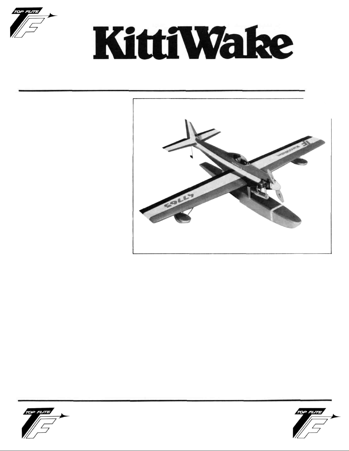
ing from .19's through .28's. The KittiWake
that is shown in the ads and on the label
of your kit has a O.S. .25 FSR installed
with a Mac's muffler. This has been an
excellent combination, providing lots of power at the top
end while offering an excellent and reliable idle. A
reliable idle is an absolute must! Face it,yourKittiWake
will have to spend a portion of each flight taxiing on the
water and without a reliable idling engine, you better
have access to a boat to go out and get it when the
engine "flames out." Take extra time to work on the idle
of the engine you choose—it will pay off later.
While on the subject of engines, it is worthwhile to point
out that the physical mounting of your engine does not
necessarily have to be a side-mount, as shown. Your
engine can be mounted up-right, at a 45 degree angle,
even inverted (although we do not necessarily like an in-
verted engine in a seaplane due to potential flooding
problems). Generally speaking, the use of a muffler on
your engine is highly recommended as it greatly
enhances the idle characteristics as well as serving to
keep you on good terms with people who may also be at
your flying site! Therefore, mounting your engine in the
nose of your KittiWake should take into consideration
the positioning of the muffler. Mounting the engine up-
right or at a 45 degree angle allows the use of most
engine's stock muffler set-ups. Side mounting the
engine, as we did, most usually requires a replacement
muffler (one with a longer header) or a header extension.
Our prototypes all used fiber-filled motor mounts, sized
for whatever engine chosen for the airplane. Your local
retailer should be able to supply you with the correct
mount for your engine.
IMPORTANT NOTE:
TOP FLITE MODELS, INC. does not recommend the
KittiWake as a first R/C powered aircraft. However, if you
are a beginner to the sport of R/C flying, we would urge
you to seek and use experienced assistance in con-
structing and flying this airplane. Again, if you are new
to this hobby, consider this:
Flying this or any other radio-controlled model aircraft is
a PRIVILEGE and not a RIGHT and this privilege begins
with the utmost safety considerations to others and
yourself as well. An R/C model airplane in inexperienced
TOP FLITE MODELS INC.
2635 S. WABASH AVENUE • CHICAGO, ILLINOIS 60616
Page 2

hands has the potential of doing serious personal or property damage. These safety considerations start at the
building board by following instructions, seeking competent help when you are confused and avoiding shortcuts. These considerations have to be carried over to the
flying field where safety must come first and limitations
cannot be exceeded. We urge you to:
1. Send for and obtain your AMA (Academy of Model
Aeronautics) membership which will provide insurance for your R/C activities — DO NOT RELY ON
HOMEOWNERS INSURANCE.
2. Join an AMA sanctioned R/C flying club in your area
where you can obtain competent, professional instruction in trimming and learning how to fly this
model.
Check with your favorite local hobby shop for the required AMA forms or the address where they can be obtained.
WARNING!!!
A radio controlled model is not a "toy." Care and
caution must be taken in properly building the
model, as well as in the installation and use of the
radio control device. It is important to follow all
directions as to the construction of this kit as well
as installation and use of the engine and radio
gear. The advice and assistance of a well experienced builder and pilot is highly recommended. Don't take chances! Improper building, operation, or flying of this model could result in serious
bodily injury to others, yourself, or property
damage.
PRE-CONSTRUCTION NOTES
The KittiWake, like other Top Flite kits employs the use of
die-cut wood to ease the task of construction, parts fit
and identification. The dies used for this kit have been
rigorously checked for absolute accuracy and should
provide you with excellent fit. Die-cut parts should be
carefully removed from their sheets by first lightly sanding the back of each sheet of parts and then carefully
removing each part. Use a light garnet paper for the sanding and keep a sharp hobby knife with an X-acto #11
blade, or equivalent, handy for assistance in removing
any parts that might not have completely cut-through by
the dies. Parts which oppose one another and must be
precisely uniform—such as ribs, etc.—should be
carefully "matched" after their removal from the part
sheets. Matching is the process of holding the opposing
pieces together with either pins, tape or spot gluing and
lightly sanding the edges of the parts until they are identical. A sanding block with light garnet paper is most
useful for this and other phases of construction.
Your building surface should be at least large enough to
accommodate the wing. This surface should be as absolutely flat as possible and yet be able to accept pins
easily. We have found that a product such as Celotex
fiber board works quite well for this purpose. Another
good surface can be found in most well-stocked hardware stores—a 2' x 4' fiber board ceiling tile. These are
quite inexpensive and can be used for several airplanes
before needing replacement.
As with most R/C kits that are constructed from wood, a
selection of tools—most of which can be found in the
average workshop—are a must to do the job correctly:
• Hobby knife and sharp #11 blades
• Single-edge razor blades
• T-pins
• Sanding blocks in assorted sizes
• Sandpaper in various grits
• Hand-held hobby saw, such as an X-acto
• Dremel tool or power drill and assorted drill bits
• Straight-edge, preferably metal, at least 36" long
•90" triangle
• Soldering iron, flux (silver) and solder
• Carbide cut-off wheel for wire cutting
• Small power jig-saw, such as a Moto-Saw
• Razor plane
• Tapes, such as masking and cellophane
Our KtttiWakes were constructed using a variety of
common hobby adhesives including 5-minute epoxy,
cyano-acrylates, and 1-hour epoxy. Since all of us have
our own construction techniques and favorite
adhesives, stick with the ones you are familiar with and
prefer. However, in certain areas there will be cal louts for
certain types of adhesives, and we urge you to try not to
substitute since doing so could possibly cause problems structurally.
The last thing we should touch on before we begin actual construction is the sequence in which the KittiWake
is assembled. The sequence given to you in this booklet
has proven to be the most straight-forward and provides
the finished components in the order in which you will
need them to progress to the next assembly phase. Try
to stick with the building order presented here to avoid
mistakes.
Spread the plans out on your work surface, cover them
with a clear plastic material, such as the backing from a
roll of MonoKote® or plastic wrap and commence construction.
WING CONSTRUCTION
It is important that you study the plans and illustrations
to understand how this wing is constructed. It is also at
this point that you make up your mind about the possible
addition of the optional landing gear set-up that we've
shown on the plans. The grooved trunnion block
material is a stock item by Sig Mfg. Co. (their #SH-655)
and the V dia. landing gear wire is bent from the pattern
provided on the plan. This set-up has worked well in actual practice. The rib reinforcements for the trunnion
blocks, RR-1 through RR-3, have been accurately
depicted for you on the plans. The addition of the optional landing gear will permit you to use the model
either on the land or in the water. Additionally, Halico
2
Page 3

sells a pre-bent, tempered aluminum landing gear that
mounts directly to the fuselage, at the forward float leg
location. Ken Willard has used this variation quite successfully (see RCM Magizine, November, 1986). The
following instructions assume the float plane version
only.
1. From their die-cut sheets, carefully remove all
wing ribs, W-1 (A and B) through W-8. Where
necessary, use a #11 blade to free the parts, making very sure that bottom tabs remain attached.
(These have been partially cut through for later
removal, should one break off, reattach it with a
spot or two of glue). If needed, lightly sand the
edges of the ribs to remove any burring. Locate
and remove die-cut (ply) parts W-9 and W-10. Addi-
tionally, locate and have ready the four 1/ 4"x 3/8"x
24"wing spars, the two 3/8 x
edges and the two 1/8" x
balsa. Of course, as we proceed with these in-
structions, you will need wing sheeting
(1/16"balsa) from the stock provided in your kit.
Protect your plans with clear food wrap or
MonoKote® backing. We will build the center
section first, followed by the outer panels.
3/4"
x 24" leading
1/4"
x 36" sub spars—all
tween the W-1 B's, about 3/8" ahead of the trailing
edge. Sand the insert as needed to fit and when
satisfied, epoxy in place. The bottom of this structure is now sheeted with 1/16" balsa from the
leading edge back to the trailing edge. Do this accurately and neatly. Use a small sanding block to
now smooth the rib/sheeting joints, keeping the
outer
(Note: The following outer wing panel construction steps assume that both the left and right
panels are built simultaneously. Also, this is the
point at which your decision about installing the
landing gear option, shown on the plans, should
be
rib
be
should now be epoxied in place to the concerned
surfaces of W-1A and B flat.
made. The patterns provided on the plans for
reinforcement parts RR-1 through RR-3 should
used to make the 1/16" Ply parts and these
ribs.)
2. Cut two 2
portant: cut one of these lengths from one piece
of spar stock and the other piece from a different
length of spar stock). From one of the leading
edge pieces, cut a
of the spar pieces directly over the plans. Now
securely pin the two rear W-1 B's in place against
the spar, making sure that they are perfectly ver-
tical to your work surface (use a triangle or block
to be sure). Now set the W-9 dihedral brace in
place on the work surface, against the bottom
spar and the two W-1 B's. Like the W-1 B's, ac-
curately position and securely pin the forward
W-1A's in place against the W-9 brace. With the
above securely in place, glue the
leading edge stock to the front of each W-1A (do
not glue to the break-away tabs). Now carefully
glue the top length of spar stock in place to the
W-1 B's. Starting from the leading edge, cut, fit
and glue all of the center-section's 1/16" balsa
sheeting in place; allow to dry.
3. Carefully remove this assembly from your work
surface. Unpin the short length of spar stock from
your work surface. Turn the assembly over and
epoxy W-10 in place against the rear face of the
leading edge and up against the top sheeting.
Carefully glue W-9 in place against the W-1A's and
B's, the top spar and sheeting. Take care here to
wipe-off any excess adhesive on the outer surfaces of the ribs and W-9. Glue the remaining
length of spar stock in place against W-9 and to
the W-1 B's. Carefully remove the bottom rib tabs
from each rib section and use a sanding block to
smooth the bottom of this structure as well as
bevel the bottom rear edge of the top sheeting.
From the kit, locate the shaped basswood wing
bolt insert. As shown, this part fits in place be-
11/16"
lengths of 1/4" x 3/8" spar stock (Im-
2-11/16" piece.
Accurately
2-11/16"
pin one
piece
of
4. Use the full cross section of the wing, the view
directly beneath the wing plan, to now accurately
cut and bevel the top and bottom 1/4" x 3/8" spars
and the
inboard W-1 ribs are angled to provide the needed
7/8" dihedral for each wing panel. In order to provide this angle uniformly to each W-1 rib section,
we've provided you with a dihedral guage, shown
here. Use this as a pattern to now makethis guage
from either scrap ply or balsa. As you did for the
center section, now pin the bottom spars accurately in place over the plans. Take care here to
ensure that they are in place straight. These bottom spars are only in place for accurate rib alignment at this time.
3/8"x3/4"
leading edges.
You'll
note that the
FULL SIZE
DIHEDRAL GAUGE
FORW1-A&W1-B
3
Page 4

5. Starting with tip rib W-8 and working inboard to
W-2, securely pin each rib in place overthe bottom
spar, making sure each is perpendicular to your
bench at 90°. Using the dihedral guage that you
made in Step 4, now accurately and securely pin
both W-1A and B rib sections in place. Note that
W-1A is spaced 1/16" ahead of the spar to compensate for the thickness of W-9 (ply dihedral brace).
Now trial-fit the pre-cut and beveled 3/8"x3/4"
leading edges in place against each rib face and
on each rib's bottom tab. Use a soft pencil to now
mark each ribs location on the leading edge and
remove. Apply glue to the marks made and glue
the leading edge in place, securing with pins.
Glue the top spar in place, W-8 through W-1B
(remember that you need a 1/16" gap for W-9, use a
scrap spacer).
6. As shown on the plans, each wing panel has a
sub-spar system which allows for the cutting and
hinging of the inset ailerons. These sub-spars are
made from 1/8" x
1/4"
balsa and the effected ribs
(W-8 through W-3) are slotted for their installation.
Cut, fit and glue the forward sub-spar in place
from W-8 to W-3. Now cut and trial-fit the rear sub-
spar in place at the rear of the slots provided in
ribs W-8through W-5. Note that the inboard end of
this sub-spar extends to and contacts W-4 and
that when in place correctly, there is an approx-
imate 1/8" gap between the front and rear subspars (this allows for 1/16" cap sheeting after the
ailerons are removed from the wing). Glue the rear
sub-spar in place.
7. From your kit, locate the 1/16" x 3" balsa sheet
stock. (Note that whenever you are applying balsa
sheet stock to a structure, it is almost always necessary to "true- up" edges by the use of a sharp
X-acto blade and a long metal straight edge.
These instructions assume that you will be doing
this as you progress.) Cut and fit the 2" wide
lengths of sheet required for the top, rear trailing
edge. Apply a moderate amount of glue to each
rib and glue this sheet in place; weight and/or pin
as needed to secure. Move forward to the top front
sheeting. Cut, fit and glue this piece in place (note
that the rear edge of this sheeting is cut to fit
halfway across the width of the spar). Now cut, fit
and glue the 1/16"x1/4" cap strips in place to the top
of each rib; W-8 through W-4.
8. Remove the wing panels from the work bench and
lay them back down, upside down. Glue the bottom spar in place. Now carefully remove all of the
tabs from the wing ribs. Use a long sanding block
to lightly smooth the bottom wing rib contours
and to bevel the trailing edge sheeting. Again,
with the panel's upside down on your bench,
locate and remove the two W-4A inboard aileron
"riblets". These are now glued in place, 1/16" outboard of W-4 (use scrap of balsa as a spacer), to
the sub-spar and top sheeting. Use a pencil to
now draw the aileron "cut-out" lines directly onto
the top sheeting. With this out of the way, cut, fit
and glue in place the bottom trailing edge
sheeting; pin and/or weight and allow to dry.
9. From your kit, locate the 10" length of slotted
hardwood tip float trunnion stock;
1/4" x 1/2"
. As
shown on the plans, you need to cut two 3-1/2"
lengths and six at 7/16"; do this now. Next,
drill
3/32" dia. hole through the 3-1/2" pieces, just outboard of the W-5 rib. This hole allows passage of
the 3/32" dia. formed main tip float wire. Trial-fit
these wires in place now. Some chamfering of the
slot and hole may be needed to allow the wire to
nest in the slot. Once satisfied, epoxy the two
3-1/2"
trunnion
blocks
in place to the front of the
bottom spar and ribs W-6 and W-5, carefully lining
up the hole just drilled with the outboard face of
W-5. Tape the formed tip float wires in place to
their trunnion blocks. Now carefully glue the 7/16"
lengths of trunnion blocks in place, over the wire
stub end, to W-5 and the top of the already-installed
3-1/2"
trunnion
block.
The resultant
positioning
of the formed wire, as shown on the plans, should
be vertical to the bottom surf ace of the wing. Note
that the remaining 7/16" lengths of trunnion stock
should first be trimmed to conform to the bottom
curvature of W-5 and epoxied in place per the
spacing shown in section C-C.
10. The bottom leading edge sheeting is now cut, fitted and glued in place, making sure that the glue
is kept out of the tip float trunnion slots and holes;
weight and/or pin as needed and allow to dry.Cut,
fit and glue the bottom 1/16" sheeting that fits over
W-5 and W-6, between the leading and trailing
edge sheets—bottom of wing only. The bottom
center section sheeting can now be cut, fitted and
glued in place. All of the bottom 1/16" x 1/4" rib cap
strips are now cut and glued in place. The last
thing to do in this step is to locate and clear-out
the
tip float trunnion slots and holes.
11. In this step you will be joining the outer panels to
the center section. If you've been careful to this
point, all that is needed is to lightly sand the inboard faces of the wing panels to render them truly flat and at the correct angle to achieve the required 7/8" dihedral. Now carefully trial-fit the
center section to each wing panel (one at a time)
to check fit. Some trimming of W-9 may be needed. Once you've achieved a good fit, prop up each
panel's wing tip 7/8" and check for the proper angle
in each panel, when in placetothecenter section;
sand and trim as needed to achieve this fit. For
joining the wing panels, we suggest an adhesive
like 30-minute epoxy as it gives you plenty of time
to work. Apply a moderate amount of glue to each
side of the center section and the rear face of W-9,
where it contacts the spars. Slide one of the wing
panels in place to the center section and gently
move it up and down a little to disperse the glue
evenly. Slip on the other panel and do the same
thing. Place the wing on your bench with the tips
supported at 7/8" each. Weight the center section
to
hold it flat. Use tape and/or pins to maintain the
a
4
Page 5

wing panel's alignment. Before leaving this structure to cure, carefully remove any oozing
adhesive from the tops of the wing panel's still exposed W-1B ribs.
12. Remove the now-assembled wing from your
bench and inspect yourwork.Useasanding block
to clean-up the joints. The leading edge of the
wing is now first razor-planed to rough shape
followed by the sanding block to achieve final
shape. Take your time here and bring these
shapes down to those shown on the plans.
13. The top of the fully sheeted center section,
behind the spar, is now opened up to accept your
aileron servo. As shown on the plans, the aileron
servo is to be installed on it's side. The opening
that you need to make should correspond with the
dimensions of your system's servo. Under no circumstances should the width of this opening exceed the inside dimensions of the fuselage interior
(2-1/8"
between the
F-2
doublers). Most radio
system manufacturers provide what is called an
Aileron Servo Tray for their servos. This is what
we've used on our prototypes and recommend to
you. The servo is mounted to the tray and the tray
can then be mounted into the opening in the
center section and to the floor. The tray can be
held in place with servo mounting tape or you can
do as we did and install a couple of scrap spruce
rails (1/4" thick) and screw the tray to the rails. You
should now make-up the aileron servo mounting
system that you're going to use. As shown, the
aileron servo's output arm is fitted with the DuBro
EZ Connector (supplied) which is used to drive
the aileron drive cable. Install this connector to
the output arm that you plan to use. (IMPORTANT
You will not need a great deal of "throw" from
your servo to the output arm and we suggest that
this connector be mounted on the output arm's
innermost hole.) Place the servo, in place to the
servo tray and with the EZ connector attached, into the opening. Now observe where the cable
housing tube (one in each panel) needs to enter
the compartment, through the W-1B ribs and
carefully mark these locations on the ribs.
Remove the servo and use a 1/8" drill bit (handheld) to drill these first two holes. Use the plans to
now drill the remaining 1/8" holes through ribs W-2
through W-5. Angle drill the tube exit holes, as
shown on the plans, just inboard of W-6 (also see
Section C-C)
14. From your kit, locate the 36" length of aileron
drive cable and drive cable tubing. Lightly sand
the surface of the tubing and cut it into two 18"
lengths. Now install the tubing into the holes
you've drilled, as shown on the plans—don't glue
yet, just get it into place with the excess protruding out of the aileron end. Working from one
side, slide the cable into the tube, working it as
needed to negotiate the corners—be patient, it'll
go. Run the cable all the way through and out the
other side, centering it in the servo compartment.
Try moving the cable back and forth a few times, it
should be fairly smooth and free. Adjust the asyet unglued tubing to achieve free movement of
the cable (a little heat from your heat gun at the
curves, really helps). Once satisfied, use slowsetting CA glue to permanently secure the tubes
at each rib station and the angled exit points—do
thiswiththecablestill in place. When dry, remove
the cable and trim the outboard angled ends of
the tubing flush with the sheeting.
15. Cut, fit and glue the top center section sheeting to
each wing panel followed by the last cap strip
pieces over the two W-3 ribs. Lightly sand the
outer faces of the W-8 ribs smooth and flat. You
can now glue the 1" x
1-1/4" x 6-1/8"
balsa wingtip
blocks in place to the W-8 ribs but NOT to the
outer ends of the ailerons. These blocks can now
be shaped and final-sanded, as shown on the
plans. The entire wing should be sanded and
smoothed to final shape.
16. Using the marks made earlier, the ailerons can
now be cut from the wing. Use a sharp #11 knife
and a straight edge. Once the ailerons are free;
sand the aileron bays smooth and straight. Cut, fit
and glue 1/16" balsa sheet over the open rib ends
and against the top and bottom sheeting, thus
closing uptheaileron bay.As shownonthe plans,
the ailerons now need to be beveled, to facilitate
free movement. Do this now with your sanding
block. Also sand the face of W-4A flat and smooth.
Before capping the face of the ailerons, you'll
need to install the two die-cut W-11 aileron horn
mounting plates (1/16" ply)
in place
as
shown. Glue
these in now. Take one of the nylon control horns
from your kit, hold it in place on the bottom of the
aileron and use a pencil to mark the hole locations for later mounting. The front face of the nowprepared aileron can now be sheeted with 1/16"
balsa. Lightly sand the ailerons, top, bottom and
ends, with your sanding block. Use the sanding
block to slightly bevel the top, front edges of each
aileron, down to the hinge line (see Sections A-A
and
C-C).
17. Using the plans, mark the hinge locations for
each aileron on both the wing and aileron. Use a
#11 blade to carefully cut the hinge slots. Temporarily install the ailerons to the wing with the
nylon hinges. Check for fit and movement and
trim as needed for a perfect fit.
Your wing is now complete with the exception of installing the 1/4"dia. dowel in the forward center section. This
will take place during fuselage construction.
TIP FLOAT ASSEMBLY
From your kit, locate the four ABS plastic tip float
halves. You should have two right and two left halves. As
you can see from the diagram and the views on the
plans, these molded tip floats are mounted over a central light-ply "core" (TF-1). These cores are slotted at the
top to accept three
3/32"
I.D. x 3/8" brass tubes. These
5
Page 6

tubes provide mounting capability to the wing. The
secret to success here is the accurate cutting of the tip
float halves from their bases, thus providing a nice,
straight edge at the center.
1. As shown in the cross-section diagram, the tip
float has to be cut from it's base. The easiest way
to do this with absolute accuracy is to make a simple cutti ng tool. We use a 4 "-5" length of 1/8" x 3/8"
spruce or hard balsa to which we glue a #11 X-acto
blade, flat, to one end of this stick with about one
half of the blade's length protruding past the end
of the stick. When this tool is laid flat on the
bench, it can provide a consistently accurate cut
1/8" above the work surface. Use a flat formica
table top for this operation. Select one of the tip
float halves and place flat on the table and hold it
firmly to the table with one hand. With your other
hand, slide the X-acto tool all around the tip float,
scoring it lightly as you go. Repeat this operation
several times until you have a definite score line
all around the piece. You should now be able to
flex the plastic at the score line until it breaks
free. Repeat this procedure with the remaining
float halves.
halfway into the center—take your time to
achieve a good fit. Once satisfied, locate the six
required lengths of brass tubing from the parts
bag in your kit. Lay the TF-1's flat on a protected
work surface and epoxy one of the tubes into each
of the slots provided. Be sure the tubes are laying
flat and that glue does not get into them and allow
to cure completely. When dry, lightly sand the
tops of these tubes flush with the top edges of the
TF-1 cores.
2. As shown, the edges of each tip float should now
be sanded lightly to absolute flatness. A piece of
#320 sand paper taped to a piece of glass or a formica table top will work great for this purpose.
Simply hold the tip float half on the sandpaper
and move it lightly in a circular motion. Just a few
passes will be needed.
3. Locate and remove the two required TF-1 light-ply
cores from their die-cut sheet. These cores now
need to be final sanded to fit exactly into the
center of the tip float halves. They only need to fit
4. In this step you are going to glue the TF-1 cores
halfway into one of the tip float halves. We suggest using a slow-setting CA adhesive for this
operation. Use your finger to apply a liberal
amount of glue around the inside center edge of
the tip float half. Now carefully insert the TF-1
core halfway into the float half and lay the
assembly down on your protected work surface
(core side down) and allow to cure. Once the glue
has set, pick up the assembly and inspect it for
any glue runs, etc. These can be quickly removed
with a single edge razor blade. Once satisfied,
trial fit the other float half in place—it should fit
accurately, even if a little pressure is required to
do so. Remove the remaining unglued half.
5. Use a 3/32" dia. drill bit to carefully open up the
ends of each of the brass tubes. The remain ing tip
float half can now be glued in place. Again apply
glue all around the inside center edge of the part
and press it in place. Tape or hold the assembly
until cured.
6. Once again use the 3/32" drill bit to clear-out the
holes in the brass tubes. The now-assembled tip
floats should be lightly sanded along the center
joint with #320 paper to true them. Some filling
may be required along this joint and for this we
would suggest something like lacquer putty (probably the best choice), available at most
automotive paint supply outlets. On our pro-
totypes, we used both PIC's "Pie N' Patch" filler
and Model Magic Filler with great results. Finally,
we suggest wet-sanding the floats with #600
paper prior to painting. These floats can be
6
Page 7

painted with a variety of available paints,
preferably sprayed. Our choice is K&B epoxy.
MAIN FLOAT CONSTRUCTION
1. Locate and remove the two FL-1 main float sides
from their die-cut sheets. Tape or pin these ac-
curately together and use a sanding block to light-
ly sand their edges smooth. Now lay one of the
FL-1 parts directly over the side view of the main
float on the plans. Use a soft pencil to accurately
mark the position of each float former—top and
bottom. Use a straight edge to draw the former
locations directly onto the FL-1 part. Do the same
thing to the remaining FL-1 part.
2. Using the
glue the top and bottom longerons in place to
each FL-1 float side—REMEMBER, you want a
LEFT and a RIGHT float side!
3. Locate and carefully remove the seven required
float formers (FL-2 through FL-8) from their diecut sheets. Now trial-fit each former in place
against each of the FL-1 float sides. Use a single
edge razor blade to make any adjustments required to achieve a good fit to the float sides and
the 1/4" sq. longerons.
4. As shown, the main float is built upside down,
directly over the plans. Start by accurately positioning and pinning in place the
"former locator" directly over the centerline on
the top view of the main float. We'd suggest using
along straight edge to be certain that this piece is
straight. Starting with the forward FL-2 former, accurately glue each former in place to the 1/4" sq.
former locator making sure that each former is 90°
upright from your work surface; a triangle is
helpful here. Securely pin each former in place.
1/4"
sq. balsa stock provided in your kit,
1/4 "
sq. balsa
5. In this step you are going to glue the float sides in
place to the formers (still pinned and positioned
overthe plans). You will need to use a slow-drying
adhesive to allow you time to work. We suggest
the slowest setting CA-type adhesive you can find
or something like 15-30 minute epoxy. Before
glueing, trial-fit the sides to the former assembly
to be sure that everything fits as it should. While
doing this, experiment with bending the float
sides to fit the formers at both ends to get some
idea of the amount of pressure required. If there
seems to be too much pressure needed to do this,
a little common household ammonia, wiped or
sprayed on the float sides, helps the wood to
bend. Assuming that you are satisfied with the fit,
you can start to glue the FL-1 sides in place. We
suggest starting by applying glue to the inside of
each FL-1 (using the pencil marks made earlier)at
the FL-5 through FL-8 former locations. Working
quickly, position each FL-1 side in place to each
former; securely pin and/or weight as needed.
Now apply glue to the FL-4 through FL-2 former
locations drawn on the FL-1 sides and bend the
sides around these three forward formers. Again,
securely pin and/or weight as needed. Allow this
assembly to dry completely.
6. Carefully unpin and remove the float assembly
from your work surface. Use a sanding block to
now smooth the top and bottom. You can also
make a few passes with the sanding block on
each of the sides. Now carefully sand the front of
former FL-2 to render it flush with the sides. Do
the same thing to the rear FL-8 former. Once
satisfied, the front and rear balsa blocks can be
glued in place. These two blocks are now shaped
to conform to the top and side views, shown on
the plans, with the exception of the tops of each
block, leave these flush with the float sides for
now.
7
Page 8

7. Cut, fit and glue the
against the rear face of former FL-5, between the
bottom longerons of the float sides (see plans).
Locate and remove the two FL-9 "discs" from
their die-cut sheet. As diagramed, these discs
break down to four pieces each. Glue these
quarter-round pieces to each other to make four
1/4"
thick parts. Sand to 90° at the corners. As
shown on the plans, these four parts are glued in
place to form the "hard points" for attaching the
aluminum float legs. Do this now.
1/4"
balsa cross piece that fits
float. Start by laying one end of this piece on the
bottom, rear of the main float, from FL-5 back to
the tail block. Use a pencil to draw the outline of
the float on the ply. Use a jigsaw to now carefully
cut-out this rear sheeting. Use the remaining
plywood for the forward, bottom float sheeting.
Use the same process to mark and cut-out this
piece of sheeting. Once again, lay the float
assembly upside down on your flat work surface.
Glue the rear ply sheet accurately in place and
use weights to hold it firmly to the float until dry.
The forward ply piece is glued in place next. This
piece requires bending to match the bottom curve
of the float, so use all necessary weight to hold
this piece in place until dry.
9. Remove the float from your bench and take the
time to inspect your work. We've made it a habit to
go back at this time and re-glue all of the joints.
Once satisfied, use your sanding block to now
sand the ply bottom flush with the float sides and
front and rear blocks.
The main float assembly is now as complete as it
needs to be. Top sheeting and final sanding will
be done in the Final Assembly phase of these instructions.
GLUE TOGETHER
IN PAIRS
8. From your
plywood. This is the bottom sheeting for the main
kit,
locate the
1/16" x 3-1/2"
x36" piece of
STABILIZER AND FIN
1. Both the fin and stabilizer are cut from the two
3/16" x
These two pieces of wood should now be edgeglued together on your flat work surface to obtain
a single 4" wide piece.
2. Using the dimensional diagram provided,
measure, mark and cut-out the stabilizer and fin.
2"
x 21" balsa sheets provided in your kit.
8
Page 9

3. Use
4. Remove the now joined elevators from your
5. Locate and remove the two R-2 parts from their
6. As shown on the plans, the leading edges of the
a sanding block to smooth each side of these
surfaces. Remove the two elevator halves and
rudder from their die-cut sheets. Lay the stabilizer
on your flat work surface and pin or weight in
place. Use a strip of clear protective material
(food wrap) to line the trailing edge of the stab.
Position the two elevator halves firmly against
the trailing edge of the stab and pin or weight in
place. From your parts bag, locate the
of 3/16"dia. dowel, this is the elevator joiner. Epoxy
this dowel in place in the slot provided in each
elevator half and allow to cure.
bench. Lightly sand the leading edge of the
elevators smooth and flat. Now use masking tape
to accurately attach the elevators to the stab, on
one side only. Turn this assembly over and use a
sanding block to sand the leading edges, tips and
trailing edges to about halfway to the cross-
sections shown on the plans. Now tape the
elevators to the stab on the sanded side, turn the
assembly over, remove the tape and repeat the
sanding procedure just described. The fin and
rudder are match-sanded in the same manner.
die-cut sheet. As shown on the plans, these are
meant to provide a hard-point at the bottom,
leading edge of the rudder for mounting the water
rudder or tail wheel. Lightly sand the edges of
these parts smooth. Lay one of the R-2 parts in
place on the rudder and trace it's outline on the
rudder with a pencil. Use a single-edge razor
blade to now cut out a 1/16" deep inset location for
the R-2 part. Repeat this operation on the other
side of the rudder. Once satisfied with the fit,
epoxy the two R-2 parts in place. Weight or clamp
this assembly and allow to cure.
elevators and rudder are beveled to facilitate
movement. Use a sanding block to now bevel
these two parts. Now use the plans to locate and
mark the hinge locations on the elevators, stab,
fin and rudder. Carefully cut the hinge slots in
each of these surfaces and trial fit them
together—do not glue hinges in place yet. Once
satisfied with the fit of these parts to each other,
use a sanding block to match them to each other
while hinged in place.
2-1/2"
length
FUSELAGE CONSTRUCTION
A review of the plans and cross-sections reveals that the
fuselage construction is basically the typical box-type
which, when completed, lends itself to rounding. Before
starting, you should have available to you the radio
system that you plan to use and the engine, tank and
motor-mount.
1. From your kit, locate and remove from their diecut sheets, the following parts; F-1 (fuselage
sides, 2), F-3 (nose doublers,2), F-2 (fuselage
doublers, 2) and the light-ply fuselage formers,
F-5 and F-6. Tape or hold the two fuselage sides
together and use your sanding block to match
edges. Lay one of the fuselage sides directly over
the side view on the plans and carefuly mark the
locations (top and bottom) of the firewall, F-5, F-6
and the 1/4" sq. balsa bracing (@D-D). Use a
straight edge to now draw these locations directly on the fuselage side. Repeat this operation on
the other fuselage side (remember, you need a
RIGHT and LEFT side).
2. With the fuselage sides laying flat on your bench,
glue the F-3 nose doublers in place. Now lay the
F-2 fuselage doublers in place, being careful to
match the wing saddle area. Observe the fit in
relationship to the lines you drew earlier. If
necessary, trim the doublers to fit precisely. Once
satisfied, glue the F-2 part in place, weight or pin
and allow to dry. From your kit, locate the four required lengths of 1/4" triangle balsa stock. Cut, fit
and glue the triangular fuselage longerons in
place, top and bottom. Cut, fit and glue the four required lengths of triangular stock to the top and
bottom of the F-3 doublers and finally, glue
triangular stock in place, directly beneath the
stabilizer slots. With the fuselage sides still down
flat on the bench, cut, fit, and glue the 1/4 " sq.
balsa uprights in place (see D-D).
3. At this point, you may wish to start planning your
radio installation by placing one of the servos on
the fuselage side, marking its location on the
wood for later placement of servo rails or servo
rail braces.You may alsowishtoplotouttheeven-
tual location of the throttle pushrod. Next, make
sure that you can pass the fuel tank you're planning to use through the opening in former
F-5—route out as needed to accomplish this. The
last thing to do before joining the fuselage sides
is to bevel each side, at the tailpost, to provide a
nice fit when the sides are pulled together (see
top view of plans).
4. Trial-fit F-5 and F-6 in place on each of the
fuselage sides; dress them with the sanding
block if needed to achieve a nice fit. Lay the right
fuselage side down flat on the bench and glue F-5
in
place using a triangle to make sure that it is
perpendicular. Repeat this process with F-6. Apply glue to the other side of these two formers and
position the left fuselage side to them. Turn the
structure upside down on your bench and pin or
weight in place—allow to dry.
9
Page 10

5. Pull the fuselage sides together at the rear to
make sure that the two sides bend equally. Once
satisfied, apply glue to the inside rear of the
fuselage sides and glue them together. Use
clamps to hold the sides together until dry. Cut, fit
and glue the top and bottom
1/4"
sq. balsa cross
braces in place at D-D.
6. From your kit contents, locate the
1/4" x 1" x 7-1/4 "
plywood piece which will be used for the main
float and wing mounting blocks. Measure, cut
and fit the rear main float mounting block which
fits directly behind F-6 and between the fuselage
sides at the bottom. It will be necessary to bevel
each end of this block to fit snuggly between the
1/4"
triangle longerons and flush with the
fuselage sides. Epoxy this block in place. The
wing bolt mounting block is now cut to fit between the F-2 doublers and against the forward,
bottom face of F-6, flush with the wing saddle.
Save the remaining length of 1/4" x 1" ply, you'll
need it shortly.
7. Remove one of the two die-cut F-7 parts from its
die-cut sheet. This part is epoxied directly over
the rear main float block just installed. Measure,
cut and glue in place the bottom rear 1/16" balsa
sheet, applied cross-grain, from the rear edge of
F-7 back to the tailpost. Use a sanding block to
sand the edges flush with the fuselage sides.
8. In this step you are going to make the necessary
provisions for mounting the completed wing to
the fuselage. Cut a 3" length of 1/4" dowel from
the stock provided. Locate
the
two
#8-32 x 1-1/2"
nylon bolts from your kit contents. Placethewing
into the fuselage wing saddle, making sure it is
square and that the fit is good. Now is the time to
make any adjustments needed. Once satisfied,
place the fuselage/wing structure upside down
on your bench. Use weights to hold the wing firm-
ly to the fuselage. The first step is to drill the required 1/4" dia. hole through F-5 (at the mark pro-
vided), the wing's leading edge, W-10 and W-9.
Remove the wing, fit the 3" length of 1/4 "dowel in-
to the hole you've just drilled (DON'T glue yet) and
re-install the wing to the fuselage, using the end
of the dowel protruding from the wing's leading
edge (about 1/4") to key into the hole in F-5. Again,
use weights to hold the wing firmly to the
fuselage. Using the plans for reference, you now
must drill the two required guide holes for the rear
wing bolts. Use a 1/8 "dia. bit, at right angles to the
bottom wing surface, to drill these two holes
through the wing and wing bolt ply plate in the
fuselage. Remove the wing. Change drill bits to
3/16" dia. and redrill the two holes in the wing, thus
allowing bolt clearance. The two holes in the wing
bolt plate must now be tapped for #8-32 threads.
This can either be done with a #8-32 tap or by us-
ing a #8-32 metal bolt. Be sure the cut threads are
clean and that the nylon bolts fit smoothly. Once
satisfied, apply a couple of drops of instant CA
glue to these threads to harden them. You can
now epoxy the
1/4"
dia. dowel permanently into
the wing's center section. Test fit the wing to the
fuselage and bolt in place. Once satisfied,
remove the wing from the fuselage.
9. In this step you must decide on what position you
want your engine; upright, side-mount, etc. Using
the plans, mark the center lines directly on the forward face of the
1/4
" ply firewall. Take care to be
accurate here. Assuming that you now know
which position you want your engine, carefully
mark the four holes required to install your mount
to the firewall. We suggest that you use #4-40 x
3/4" socket head bolts and blind nuts to attach
your mount. Drill the required holes, epoxy the
blind nuts in place and removethemountfromthe
firewall. The firewall can now be epoxied in place
between the two fuselage sides, Clamp in place
until cured.
10.
From the remaining length of 1/4" x 1" plywood,
measure, cut and fit the forward main float mounting block in place to the forward face of F-5, flush
with the bottom fuselage sides. Note that this
block must be slightly routed out at the center to
allow clearance for the wing's mounting dowel;
dothisnow. Epoxy this block in place and allow to
cure. Epoxy the remaining F-7 plywood part
directly over the main float mounting block just
installed.
11. Remove spinner ring former F-4 from its die-cut
sheet. As shown, this part fits directly to the front
of the two fuselage sides. Trial-fit F-4 in place by
bending the fuselage sides together, at the nose,
until the outer diameter of F-4 matches the outer
edges of the fuselage sides. This necessary bending can be made easier by wiping some ammonia on the fuselage sides in the area of the bending stress. F-4 must be accurately located.
Epoxy F-4 in place and clamp securely until
cured.
12. Sheet the bottom of the forward fuselage, from
the leading edge of the firewall back to the forward edge of the F-7 part, use your sanding block
to smooth the sheeting to the fuselage sides.
From your
kit,
locate
the two 3/8"x3"x3-1/2"
balsa
nose blocks. As shown on the plans, these are
now trimmed and fitted into place from the rear of
F-4 back to the front face of the firewall, top and
bottom. Usethe sanding blockto sand them flush
with the fuselage sides after gluing in place.
13. While we still have access to the inside of the
fuselage through the top, there are a couple of
things we can take care of at this time. First,
locate four (4) #4-40 blind mounting nuts from
your hardware package along with one #4-40 bolt.
Using the plans as a guide, you now need to mark
the positions of the four required holes to mount
the aluminum float legs to the fuselage. As
shown, these holes are positioned 7/8" on each
side of the fuselage/float leg centerline (see
cross-section). From your kit box, locate the two
10
Page 11

aluminum float legs. Use a ruler, triangle and a
sharpened nail (or scribe) to accurately mark the
vertical centerline on both float legs. Now use a
soft pencil and a ruler to mark the fuselage's
centerline of both of the F-7 ply plates, on the bottom of the fuselage. Use a small amount of CA
glue to now tack glue the as-yet unbent float legs
accurately in place on the bottom of the fuselage,
carefully lining up the centerlines. Now mark the
hole locations directly on the float legs and with a
7/64"
dia. drill bit, drill these holes through the
aluminum, F-7 and
at a time, apply epoxy to the edges of the blind
mounting nuts and, using a screwdriver and the
#4-40 bolt, cinch the glued nut down into the hole,
from the inside. Once all four nuts have been installed in this manner, carefully remove the tack
glued float legs from the fuselage.
The next thing to do at this time is to make all the
necessary provisions for mounting the rudder,
elevator and throttle servos. As shown, we have
mounted the servos as far back in the radio compartment as possible and close to the bottom of
the top sheeting. We used the radio
manufacturer's stock servo mount (plastic),
which allowed for all three servos to be mounted
side-by-side. However, there's plenty of room for
the throttle servo to sit ahead of the other two, as
shown on the plans. Doing this now makes servo
installation later a simple matter of a few screws.
1/4
" ply mounting blocks. One
viewed from the top, is squarely in position
relative to the wing. Use a piece of string or a ruler
to be sure that the distance from one wingtip to
the tip of the stabilizer is the same measurement
on each side. Glue the stabilizer in place and
allow to dry. Next, the fin is glued in place. Again
make sure that the fin is absolutely vertical to the
stabilizer and wing. Tape and/or pin in place and
allow to dry.
14. From your kit, locate the 3/8" x 3" x 30" balsa sheet
used for the top fuselage sheeting. Sand the front
edge to match the rear edge of the noseblock,
already in place. Cut and sand the rear edge to
match the tailpost angle.
should now be cut in the rearto provide for moun-
ting the fin. Hold the sheet accurately in place to
the fuselage and use a soft pencil to mark the
fuselage outline on it. Use a jigsaw to remove the
excess material. Glue the top sheet in place to the
top of the fuselage and rear of the top noseblock.
Lay the assembly upside down on the bench and
weight in place until dry. Once dry, use a sanding
block to smooth the edges flush with the fuselage
sides.
15. The fuselage can now be shaped and sanded to
final configuration, using the plans and cross
sections for reference. We'd suggest first using a
sharp razor plane to rough shape the fuselage,
followed by progressively lighter grades of sand-
paper to achieve final shape and surface
smoothness. Take your time here to get those
sexy lines that you admired so much in both the
ads and the box art!
16. With the wing bolted in placetothe fuselage,trialfit the stabilizer in place in the slot provided. Set
the assembly flat on atable and step back to sight
down the front of the model—everything should
look straight. If it isn't, some sanding and adjustment of one of the slot sides may be needed. If so,
do this now. Next, be sure that the stabilizer, when
As
shown, a
3/16"x
2"
slot
17. Locate and remove die-cut sub-fin R-3. This part
has a "lobe" on it's forward end which should
now be sanded-off to match the plans. Tape the
rudder in place to the fin. Trial-fit R-3 in place to
the bottom rear of the fuselage. It's rear edge
should match the rudder's angle and depth at this
point. Once satisfied, glue R-3 in place (leave the
rudder taped to the fin). Once the glue has dried,
use a sanding block to match the R-3 sub fin to the
rudder shape. Use sandpaper to round R-3 to
shape (see E-E).
18. The engine compartment opening is now made.
We suggest starting with a small hole over what
would be the top of the engine's head and working
outward from there. The idea here is that you want
the opening to be large enough to fit the engine in
place (at this point; without the muffler mounted
yet) by hand, but not overly large. Once you can fit
the engine in and out of the opening, try the motor
mount. With access through the spinner ring
(F-4), bolt the motor mount firmly in place to the
firewall. Now fit the engine in place to the motor
mount. Slide the engine forward and attach the
spinner (we use the stub of an old 9x6 prop for a
spacer). Now slide the engine back until the back
of the spinner contacts the F-4 spinner ring. With
a few scraps of 1/32" material (balsa or ply), space
11
Page 12

the back of the spinner 1/32" from the front of F-4.
This is the position that your engine should be for
drilling the holes in the motor mount. Mark these
engine lug holes now, on the motor mount with a
pencil or scribe. Remove the engine, spinner and
motor mount. Accurately drill the four required
holes in your motor mount (Note: For .25-sized
engines, we suggest using #4-40 socket head
bolts and tapping the motor mount for #4-40
threads.). Reassemble the mount, engine and
spinner to check for accuracy of fit. With
everything still in place, positioning of the two
fuel line holes (fuel feed and muffler
pressure/overflow venting) and the throttle
linkage should be noted on the firewall for drilling. The last thing to make provision for is the fitting of your engine's muffler with sufficient
clearance. Do this now.
Remove all of the above components from the
front of your fuselage. Using a longer drill bit of
the correct (never oversize) diameter to the fuel
tubing and throttle linkage housing, drill the
holes marked earlier through the firewall. It is at
this point that we suggest a coat of polyester
resin be given to the inside of the engine compartment and firewall (don't get any in the holes for
the motor mount). We also like to use resin inside
of the tank compartment and on the rear face of
F-5.
19.
Use the same method described in the TIP FLOAT
ASSEMBLY section to accurately cut the molding
base off of the canopy. Next, securely tape a
sheet of #220 sandpaper over the area that the
canopy is to be mounted on the fuselage. Careful-
ly sand the base of the canopy to conform to the
top of the fuselage (it won't take much since the
fuselage, at this point, is only slightly rounded).
Once the canopy fits, hold it in place exactly
where you want it to be, and use a soft pencil to
draw its outline on the fuselage. If you wish, as we
did, to add cockpit detail, now is the time. We used a Wm. Brothers pilot head, suitably cut-down
to fit, scraps of black construction paper and a
few instrument decals we had laying around to
make a reasonable-looking cockpit. Once
satisfied, the canopy can be glued in place to the
fuselage with a slow-setting CA glue—tape or
hold and allow to set.
20.
There are some good fillet materials currently on
the market which we have used and recommend;
Penn's "Pie N' Patch" and Model Magic Filler.
Use the one that you're most comfortable with to
now apply a small fillet around the canopy (tape it
off with electrical tape) and around the
fin/fuselage, stabilizer/fuselage and subfin/fuselage joints. You should also lookoveryour
fuselage carefully for any nicks, dings or voids
and fill these at this time. Once the filler has set,
use a light grade of sandpaper to smooth these
out. You should now cut the last required hinge
slot in the rear edge of R-3 for rudder attachment.
FINAL ASSEMBLY
I. MAIN FLOAT ASSEMBLY
Back in the construction of the fuselage (Step 13), you
drilled the two required mounting holes in each of the
two unbent aluminum float legs. The float legs must
now be accurately bent to provide fit and attachment to
the main float and the plywood "hardpoints" built into it.
Take a look at the cross section shown on the plans of
this fuselage/float leg/main float relationship. You can
see that the float legs must be bent equally on each side
and that, at the bottom, they are bent slightly once again
to pick-up the vertical float sides. In all of this, the
fuselage/float relationship must provide for a.) proper
propeller clearance (9" dia. max prop size) and b.) the
correct angle of attack for the wing/fuselage/engine
combination.
1. Hold the float leg, straight edge down, vertically
in place on your flat bench. With a triangle and
scribe (sharpened nail will do) mark two vertical
lines on the float leg, each 1
-1/4"
on either side of
the centerline that you marked earlier. This provides you with an accurate
2-1/2"
inside bending
location. Place the float leg into a vice with a
piece of hardwood on each side of it (see
diagram) and make the first bend directly along
the line just marked on the part. This bend is made
by "eyeballing" the drawing provided. Turn the
part over and make the second bend. Remove the
part, lay it over the drawing to check for how close
you came. Continue this process until the part
matches the drawing. Repeat this procedure for
the other float leg.
12
Page 13

2. The method we suggest for locating the fuselage
to the main float istomakeapairoffrontand rear
scrap balsa stand-offs. These stand-offs are then
tack glued to the top of the main float and provide
a place for the fuselage, with the float legs attached, to accurately rest. The dimensions we used
are those directly behind the front float leg location,
beneath
rear float leg, beneath
F-5
(2-1/16")
and directly ahead
F-6
(2-1/4").
These two
dimensions take into consideration that the top
of the float has not yet been sheeted.
3. With the fuselage, float legs attached, now sitting
accurately over the main float, you can view the
assembly from the side and use a pencil to mark
the float leg ends for the second bend needed to
fit the vertical main float sides. These bends can
easily be done with a pair of pliers. Take a little
time to "tweek" these bends to achieve a good fit.
4. The bolt hole marks on each float leg end should
now be made. Remove the fuselage from the main
float and the stand-off fixtures (leave the stand-
offs in place) and remove the legs from the
fuselage. Drill the bolt holes accurately through
each leg end with a 7/64"dia. drill bit. Re-assemble
the legs to the fuselage and place the fuselage
back on the main float. Use the same drill bit to
now drill holes through the main float sides and
the plywood hard points. Install the four #4-40
blind nuts into the ply hard points with epoxy and
allow to cure.
5. Remove the fuselage from the main float and
remove the stand-off jigs from the main float top.
The top of the float can now be sheeted with the
1/16" balsa provided and shaped and sanded to
final form (see plans and cross sections). PLEASE
note that the bottom edges of the float are NOT
rounded, they are sanded to sharp, precise corners.
II. TIP FLOAT WIRE BRACES
1. Locate the 18" length of 3/32"dia. wire from your
kit. This wire is purposely untempered to allow
easy bending with common pliers. A carbide cutoff wheel in your Dremel Tool should be used to
cut this wire as needed. Accurate bending pat-
terns for these braces (2 per float, front and rear)
are shown on the right side cross section view of
the wing. Use the patterns to now bend and cut
the braces.
2. Now trial-fit the tip float and the supporting wire
braces in place to the wing. Use your pliers to ad-
just as needed for an accurate fit. Section C-C on
the plans demonstrates the correct relationship
of the tip floats to the wing. Once satisfied, set
these parts aside for later assembly after cover-
ing.
of
the
III. WATER RUDDER
1. Locate
the
two solder
clips,
the
1/16"
dia.
x 5-1/4"
wire arm and the 3/4 "x 1-1/4" piece of tin from your
kit parts. These are used to make the water rudder
system shown on the plans. We suggest using
Harris "Stay-Clean" solder flux for the required
soldering operations. Once the water rudder
assembly is made, carefully clean it off and round
the tin rudder as shown. On our prototypes, we
sprayed this part flat black with K&B epoxy. This
is not necessary but it looks very "finished".
IV. GENERAL
1. Bolt the wing to the fuselage. How does the wing
saddle fit look? It should be an excellent fit
because if it isn't water will find its way inside.
Now is the time to correct any gaps and achieve a
good fit. We suggest mixing up a thick mixture of
30-minute epoxy and white micro-balloons and
spreading this mixture directly onto the fuselage
wing saddle area. Cover the center section of the
wing with clear MonoKote backing to protect it
and then mount and bolt the wing in place. Allow
the micro-balloon filler to cure, remove the wing
and sand the fuselage sides smooth. The result
will be a perfect wing/fuselage fit that will not require any additional sealing.
2. On our prototype KittiWakes we used no fiberglass
for strengthening parts. However, you may wish
to do so. We suggest using only 3/4 oz. fiberglass
and only using this material in certain, small
areas such as the bottom, leading edge of the rudder, a square inch or so over each of the four bolt
holes in the main float, etc. Fiberglassing the en-
tire float is not needed and doing so could cause a
major weight gain.
COVERING
As mentioned right from the beginning, our prototypes
have all been covered and flown with MonoKote® covering. The airplane depicted on the label of your kit is totally covered with MonoKote, including the aluminum pinstriping and the tip floats (which were initially handcarved, shaped and hollowed from light balsa)! This
airplane has been flown a great deal as well as displayed at the various trade-shows and still, to this day,
looks fabulous. This demonstrates the viability of
MonoKote® as a covering for seaplanes and we highly
recommend it's use.
The tip floats, being plastic, lend themselves best to
paint. We have used and highly recommend sprayed
2-part epoxies, such as K&B or HobbyPoxy. These paints
were also used on our prototypes for areas such as the
water rudder assembly, inside the engine compartment
(flat black), the control horns (dark blue), the top of the
canopy (red) and the aluminum float legs (aluminum).
We suggest that all of the various components that are
going to be covered with MonoKote should first be
wiped with a tack rag or blown off with high pressure air
to remove any dust particles. Each component should
13
Page 14

be covered separately (elevators, rudder, ailerons, wing,
fuselage, etc.). After covering, locate and open up all required access points; hinge slots, bolt holes, etc. For
seaplane operations there really isn't much difference
in covering methodology other than being careful of
each required opening in the airframe. A structure such
as the main float, for instance, has requirements for four
holes (the float leg attach points). Common sense dictates that when the float legs are bolted in place to the
main float, the bolt threads should first be lightly coated
with a silicone sealer (best) or at least a coat of Vaseline.
While still on the subject of the main float, this particular
structure should be very carefully covered with the
overlapped seams measuring about 3/16" - 1/4". Additionally, these seams should be carefully worked over
with your MonoKote iron to be very sure they're in place
for good. It's taking the time to do these kinds of things
that has made MonoKote work so well for us on our prototypes.
After covering, the elevators, rudder and ailerons can be
hinged in place. We've made it a practice to drill a few
3/32" dia. holes on each side of the hinges, before installation, to allow the epoxy to flow and act as "pins"
when cured. As you proceed, keep a small amount of
acetone handy to wipe-off any excess epoxy.
The tip floats and tip float braces can now be installed
on the bottom of each wing panel. The method that
we've used to do this is simple and fast. First, install the
formed main tip float wire into it's hole and slot and
secure with the wood screws and washers. The front and
rear tip float brace wire-forms have already been bent
and pre-fitted earlier. Apply a slow-setting CA adhesive
to the ends of the braces and main tip float wire that fit
into the tip float itself and insert the front and rear wire
ends into the tip float, in approximately the correct positions. Now apply just a little CA adhesive to the opposite
ends of the wire braces and press this assembly into
place in the holes. If you need to remove the tip floats
from the wing, all you need to do is to remove the screws
and washers, flex the brace wires a couple times and the
assembly will come out.
The nylon control horns can now be permanently
mounted to the rudder, elevators and ailerons. Again,
we'd suggest silicone adhesive on the threads.
As mentioned earlier, we suggest a coat or two (brushed
is fine) of epoxy paint (K&B or Hobby Poxy) for the engine
compartment. Flat or satin black is our favorite because
it's neutral and easy to see when brushing. Once this is
done, the motor-mount, engine, muffler, fuel tank and all
necessary plumbing can be installed. The water rudder
won't be attached until after the radio is installed and
the airplane is assembled.
RADIO INSTALLATION
If
you have followed these instructions to this point, the
physical mounting of the four required servos should only be a matter of a few screws. This should be done now.
As
mentioned earlier in the Wing Construction steps,
the
aileron drive mechanism consists of the single
length of braided steel cable, driven at the center by the
aileron servo. Solder one of the threaded brass couplers
ononeendofthiscableand inserttheotherend intoone
of the openings at the aileron location on the bottom of
the wing. Feed the cable through and into the servo compartment, through the EZ connector on the servo's output arm and then into the tubing opening for the other
wing panel. Continue feeding the cable through this
panel until it exits on the other side. Attach one of the
nylon clevises to the threaded coupler and attach the
clevis to the aileron control horn. Use scraps of tape to
hold the ailerons in neutral. Now measure how much
cable needs to be cut-off in order to solder the remaining
coupler in place with a clevis attached. Mark and cut-off
this length of cable with a carbide cut-off wheel, lightly
tin the cable end, and solder the coupler to it. Attach the
clevis to the coupler and make the connection to the
aileron control horn. The clevises can now be adjusted
to center the ailerons and once satisfied, the set screw
in the EZ connector can be tightened. Test the action of
this mechanism with your radio system and make any
adjustments required.
1/4" dowel stock has been provided for the rudder and el-
evator pushrods, make and install these now. We sug-
gest you use 3/32 "dia. wire at the servo end of these push-
rods with either DuBro EZ connectors or "Z"-bends.
Don't use threaded clevises.
Assuming the throttle linkage of your choice has been
installed and works, make that connection to the throttle servo. The switch on our prototype was mounted internally (almost a "must" with seaplanes), against the
bottom of the fuselage top sheeting, just ahead of the
servo tray. A short length of wire through the fuselage
(use a close-fitting grommet of some sort; plastic tub-
ing, etc.) is then i nstal led to activate the switch external-
ly. If you look closely at the KittiWake on the box label, you
can see this on/off wire, just below the name on the
fuselage.
You should now make an exit for your receiver's anten-
na. We suggest that, like the switch, this exit be as high
up on the fuselage side as possible and that this exit
also be grommeted. Attach the other end of it to the top
of the fin with a wire hook and rubber band.
The only real water-proof ing measure that we took, other
than building the airplane tight to begin with, was wrapping the battery pack in clear plastic. The receiver and
battery pack should now be installed, remembering that
their positions may have to be changed for Center
of
Gravity needs.
Assemble your model completely and turn on the
switch. First make very sure that the ailerons, rudder and
elevators move in the correct directions by transmitter
command. Now you need to set-up your surface movements for initial test flights. The following is what we
suggest for first flights:
ELEVATORS.......... .5/16" from neutral 5/8" total
RUDDER................All available movement
AILERONS............
1/4"
from neutral 1/2" total
The above movements provide crisp control of the
model. If you have dual rate capability on your transmit-
ter, you may wish to decrease these movements slightly.
14
Page 15

The last thing to do is balance the model. The C.G.
shown on the plans is exactly where we have been flying
our prototypes. We've gone as far as 1/2" fore and aft of
this location and still had a managable airplane but not
necessarily a "happy" airplane. Therefore, do whatever
is needed to achieve the C.G. location shown and recommended.
After fully charging your radio system, you can head
the pond!
FLYING
Assuming that you have followed the instructions and
made sure that the engine is performing well, let's head
for the lake! The flying site that you choose is very important. It should offer you clear, unobstructed take-off and
landing room and it should also have access to the
water; a bank, stretch of sand, low pier, etc. Never, at any
time, should you operate your KittiWake when the water
is being used by swimmers or boaters. The last precaution we'll throw in here is that it is extremely unwise to
operate your KittiWake out of salt water. Salt water can
and will attack almost all metals, including battery
packs, receiver P.C. boards and servos. And it does so in
a matter of seconds. Fresh water on the other hand really does not hurt the electronics of a radio system, as long
as the system is given the opportunity to dry out between "dunkings". Our prototypes have not shown a
tendency to take on water and the fact that the radio
system is "suspended" in the upper part of the fuselage
does a great deal in protecting the system from sitting in
any pooled water that may get in.
It
does pay to create the best possible fit between the
wing and fuselage to minimize leakage.
Fill your tank and start the engine. From the work you've
done at home, the radio system should have already
been checked for any problems with vibration. After
making sure that all of the controls are moving in the correct directions, launch the airplane onto the water.
First try the action of the water rudder. This rudder
system works best at low speeds. You will find that the
faster the aircraft is moving, the less effective the water
rudder is. Do you have enough movement? In other
words, can you steerthe model comfortably in any direction? Remember that wind will effect the steering of the
model and that some additional time turning into the
wind may be required. What we are trying to find out in
these taxi tests is if we have enough steerage to easily
handle the model but not so much as to render it
"touchy".
If you find you need more steerage, return the model
shore and induce more movement into the flying rudder
by moving the clevis in, to the next hole. Try taxiing
again.
Once you're comfortable with the water handling characteristics, turn the airplane into the wind and advance
the throttle smoothly to about 1/3 rd. You'll find, as you do
this, it may be necessary to hold a small amount of right
rudder to compensate for intitial torque. The idea is to
hold the aircraft in as straight a line as possible while
proceeding upwind. Watch your airplane carefully. At
to
1/3 rd throttle you should be able to notice that it wants
come up on the step and, depending on your engine, it
may already be on the step. This is the point that a
seaplane must reach in order to take-off. It is possible
that your model is now planing on the step. Try this a
couple of times to get used to this transition phase of
your model. You should now be ready to try a take-off.
to
Again head the KittiWake into the wind, advance the throttle smoothly and look for the transition of the model onto
the step. After a few yards on the step to build-up speed,
the model will essentially by flying. A little back
pressure on the elevator stick should lift the model off
the water. Do Not lift the model off before reasonable flying speed has been reached.
Once airborne, grab some altitude and start the process
of checking out the effectiveness of the flight controls—remember that, if you have dual rate capability
with your radio system, you can increase or decrease
flight surface throws. Once you have the model settled
down and trimmed for straight and level flight, take the
time to idle back the engine and find out what a stall is
like while still at altitude. Our prototypes, balanced as
shown, stall rather cleanly with recovery almost instan-
taneous. The further back your C.G. is, the more the ten-
dancy will be to tip stall. Once you've seen some of the
low-speed characteristics of your KittiWake, you should be
a bit more comfortable with the landing.
Landing a seaplane is not too different from landing any
other type of model with the exception that it is important to keep the wings level. You want to land your airplane on the main float, not the tip floats. A couple of
feet off the water, start a gentle flare, to allow the main
float to just skim across the water—don't pancake the
float onto the water, you'll just ricochete back into the
air again. With the float skimming across the surface of
the water, chop the throttle and allow the model to settle
into the taxiing speed and return to shore.
Now is the time to relax a bit and think back about what
trim changes, if any, are needed. Make these now. Get
airborne again and start finding out the performance
capabilities of your KittiWake. We think you'll be truly impressed.
We sincerely hope that you have enjoyed this project
and that your KittiWake will be the source of many happy
hours spent at the lake!
INDEX
INTRODUCTION
PRE-CONSTRUCTION NOTES
WING CONSTRUCTION
TIP
FLOAT
MAIN
STABILIZERANDFIN
FUSELAGECONSTRUCTION.................. 9
FINALASSEMBLY
COVERING
RADIO INSTALLATION
FLYING
CONSTRUCTION
FLOAT
.................................... 15
............................
.................
......................
..................
CONSTRUCTION
........................
........................... 12
................................. 13
....................... 14
................
to
1
2
2
5
7
8
15
Page 16

150005
 Loading...