

Page 1
RC-34 INSTRUCTION MANUAL
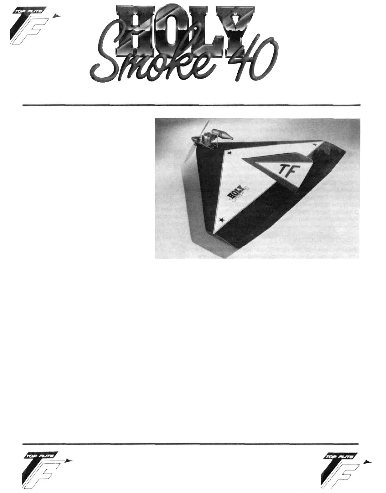
INTRODUCTION
Holy smoke, what a name for an airplane!
The name was derived from comments
made by other modelers when they saw
this delta fly for the first time. From a
marketing standpoint, we're very happy
that the standard comment was not "Holy
Cow"!
The delta that we are presenting in this kit
was designed by Hal Parent! and it has a
long and successful history. The design is
exceptionally easy to fly due to its inherent stability and will accept a fairly
broad range of engine sizes (2-cycle) and
still remain flyable and fun. The design
itself is the essence of simplicity. We feel
that it is entirely possible to start construction on a Monday evening and have it
ready to fly by the following Saturday. It
may well be the perfect "other" airplane.
The "H.S. 40" has been test-flown off of grass fields as
well as asphalt with uniformly good results. When
powered with one of today's strong-running .40 engines
(Enya CX, O.S., etc.), the take-off is short and to the point.
We have test-flown the airplane with engines as small as
.25 (an 0.S. FSR) and it still flys quite nicely. Those of you
who may be considering the installation of a .60 engine
might first strongly consider one of the .40's or .45's
mentioned earlier. A .60 is going to give you some balan-
cing problems which might well result in a rather heavy
airplane.
The radio installation in your H.S. 40 is straight-forward
and the radio/tank compartment is roomy enough for all
but the largest of servos. As with most R/C models, the
radio installation should be made with achieving the
correct Center of Gravity as the goal. If your battery
pack, for instance, has to be located at the rear of the
radio compartment in order to achieve the correct C.G.,
that's fine and superior to having to add lead. The installation shown on the plans is typical of our prototypes; yours may be different due to varying radio components and engine weights.
Flying your H.S. 40 should prove to be a delight. There
just aren't many maneuvers that this design is not
capable of. The possible exception might be those
maneuvers which require some rudder.
IMPORTANT NOTE:
TOP FLITE MODELS, INC. does not recommend the
Holy Smoke 40 as a first R/C powered aircraft. However, if
you are a beginner to the sport of R/C flying, we would
urge you to seek and use experienced assistance in constructing and flying this airplane. Again, if you are new
to this hobby, consider this:
Flying this or any other radio-controlled model aircraft is
a PRIVILEGE and not a RIGHT and this privilege begins
with the utmost safety considerations to others and
yourself as well. An R/C model airplane in inexperienced
hands has the potential of doing serious personal or property damage. These safety considerations start at the
building board by following instructions, seeking competent help when you are confused and avoiding shortcuts. These considerations have to be carried over to the
flying field where safety must come first and limitations
TOP FLITE MODELS INC.
1901 NORTH NARRAGANSETT AVENUE • CHICAGO. ILLINOIS 60639
Page 2

cannot be exceeded. We urge you to:
1.Send for and obtain your AMA (Academy of Model
Aeronautics) membership which will provide insurance for your R/C activities — DO NOT RELY ON
HOMEOWNERS INSURANCE.
2. Join an AMA sanctioned R/C flying club in your area
where you can obtain competent, professional instruction in trimming and learning how to fly this
model.
Check with your favorite local hobby shop for the required AMA forms or the address where they can be obtained.
WARNING!!!
A radio controlled model is not a "toy." Care and
caution must be taken in properly building the
model, as well as in the installation and use of the
radio control device. It is important to follow all
directions as to the construction of this kit as well
as installation and use of the engine and radio
gear. The advice and assistance of a well experienced builder and pilot is highly recommended. Don't take chances! Improper building, operation, or flying of this model could result in serious
bodily injury to others, yourself, or property
damage.
PRO-CONSTRUCTION NOTES
The Holy Smoke 40, like other Top Flite kits employs the
use of die-cut wood to ease the task of construction,
parts fit and identification. The dies used for this kit
have been rigorously checked for absolute accuracy
and should provide you with excellent fit. Die-cut parts
should be carefully removed from their sheets by first
lightly sanding the back of each sheet of parts and then
carefully removing each part. Use a light garnet paper
for the sanding and keep a sharp hobby knife with an
X-acto #11 blade, or equivalent, handy for assistance in
removing any parts that might not have completely cutthrough by the dies. Parts which oppose one another
and must be precisely uniform—such as ribs,
etc.—should be carefully "matched" after their removal
from the part sheets. Matching is the process of holding
the opposing pieces together with either pins, tape or
spot gluing and lightly sanding the edges of the parts until they are identical. A sanding block with light garnet
paper is most useful for this and other phases of construction.
Your building surface should be at least large enough to
accommodate the wing. This surface should be as absolutely flat as possible and yet be able to accept pins
easily. We have found that a product such as Celotex
fiber board works quite well for this purpose. Another
good surface can be found in most well-stocked hardware stores—a 2' x 4' fiber board ceiling tile. These are
quite inexpensive and can be used for several airplanes
before needing replacement.
As with most R/C kits that are constructed from wood, a
selection of tools—most of which can be found in the
average workshop—are a must to do the job correctly:
• Hobby knife and sharp #11 blades
• Single-edge razor blades
• T-pins
• Sanding blocks in assorted sizes
• Sandpaper in various grits
• Hand-held hobby saw, such as an X-acto
• Dremel tool or power drill and assorted drill bits
• Straight-edge, preferably metal, at least 36" long
• 90" triangle
• Soldering iron, flux (silver) and solder
• Carbide cut-off wheel for wire cutting
• Small power jig-saw, such as a Moto-Saw
• Razor plane
• Tapes, such as masking and cellophane
Our Holy Smoke 40's were constructed using a variety of
common hobby adhesives including 5-minute epoxy,
cyano-acrylates, aliphatic resin (such as Titebond) and
1-hour epoxy. Since all of us have our own construction
techniques and favorite adhesives, stick with the ones
that you are familiar with and prefer. However, in certain
areas there will be callouts for certain types of
adhesives, and we urge you to try not to substitute since
doing so could possibly cause problems structurally.
The last thing we should touch on before we begin actual construction is the sequence in which the Holy
Smoke 40 is assembled. The sequence given to you in
this booklet has been proven to be the most straightforward and provides the finished components in the
order that you will need them to progress to the next
assembly phase. Try to stick with the building order
presented here to avoid mistakes.
Spread the plans out on your work surface, cover them
with a clear plastic material, such as the backing from a
roll of Monokote or plastic wrap and commence construction.
LEADING EDGE CRUTCH ASSEMBLY
The Leading Edge Crutch serves to "tie together" all ten
of the wing ribs and align them at the same time. This
assembly should be built flat over the plans. Be sure that
your plans are covered with either the clear backing from
a roll of Monokote or a clear food wrapping material.
1. From your kit box, locate the two pieces of 1/8" x
1-3/16" x 28" balsa sheets that will become the leading
edge crutches. Lay these directly over the plans and
carefully cut each end to fit as shown. The outer end
is cut to fit against the inside face of tip rib W-5 while
the inner end is cut at an angle corresponding with
the centerline of the airplane. Once satisfied with
the fit over the plans, glue the two crutch pieces
together at the center, pin parts accurately over the
plans.
2. From your die-cut sheet RC-34-2, carefully remove
parts W-6A and W-6B. Glue W-6A to W-6B to form a
triangle. Fit the finished W-6A/B part in place directly behind the leading edge crutch assembly at the
center. You might have to lightly sand this assembly
for a nice fit. Once satisfied, glue this part in place,
directly over the plans.
2
Page 3

3. Locate die-cut sheet RC-34-1 (2 req'd.) and remove
the two Motor Mount Fillers. These are now glued in
place against the leading edges of the two leading
edge crutches, at the nose, directly behind the spinner shown on the plans. Now use your sanding block
to lightly smooth off the glue joints. From the ply diecut sheet RC-34-6, remove the two W-7 parts. Use
your sanding block to clean up their edges. Glue one
of the W-7 parts directly on top of the leading edge
crutch assembly, aligning its rear edge with the rear
edge of W-6B and its forward edges with those of the
two motor mount fillers. Use weights to make sure
that W-7 stays flat against the leading edge crutch
assembly until it is dry.
4. Remove the leading edge crutch from the plans, turn
it over and use your sanding block to smooth out any
glue joints. Glue the remaining W-7 part in place to
the bottom surface of the crutch assembly, exactly
aligned with the W-7 previously glued to the top surface. Again, use weights to hold this part in place
and allow it to dry.
Remove this assembly from your building board as
we will now build the rest of the airplane.
GENERAL CONSTRUCTION
1. From the die-cut sheets provided, carefully remove
all of the required wing ribs W-1 through W-5, two of
each. Note that these ribs each have temporary
"tabs" attached to the front and rear ends (W-2 and
W-3 have them in the center as well). These are there
to provide stability during construction on a flat sur-
face—do not remove these until told to do so. Use
pins to now locate each rib in its appropriate posi-
tion over the plans and vertical to your work surface.
We would suggest using a 90° triangle to be sure
that the ribs are truly vertical.
2. Carefully slide the previously built leading edge
crutch assembly into the slots provided on the front
of each rib (except W-5). The ply W-7's should fit on
the inside faces of the two W-1 's at the nose and the
outer ends of the crutch assembly should be in contact with the inner surfaces of the two W-5's. It may
be necessary to trim a little here or there to achieve
the proper fit. If so, do it now.
With the crutch still in place but not yet glued, turn
your attention to the slots provided in the ends of
each rib. Locate the 3/32" x 7/8" x 36" bottom trailing
edge balsa piece provided in your kit and carefully
slide it into place in the rear rib slots.
Now take the time to inspect this structure for cor-
rect alignment and that each piece is indeed contacting the other in the previously described manner.
Once satisfied, glue the leading edge crutch and
trailing edge piece to each rib. A slow-setting CA is
just the ticket here. Don't worry about getting glue
onto the bottom of the crutch assembly, we'll do that
when we remove the structure from the building
board.
3. From die-cut sheet RC-34-2, carefully remove former
W-9. Lightly sand the edges of this part to fit in place
between the two W-1 ribs and against the rear edge
of the crutch assembly. Note that the "peaked" side
of W-9 is the top. Once satisfied, glue W-9 in place,
again being sure that it is vertical to your building
surface.
4.There are four(4) 3/16"x3/8"x24" wing spars provided
in your kit; locate two of them. Bevel the inboard
ends of these spars to fit against W-9 as shown on
the plans. Test fit the spars in place in the slots provided. Once satisfied, glue these spars in place. Trim
the outer ends flush with the outer faces of the two
W-5's.
5. Use light sandpaper and your sanding block to now
bevel the front edges of each rib flush with the
leading edge crutch. From your kit box remove the
two 1/2" x 1-1/8" x 36" balsa strips provided. These are
the leading edges and wingtip material. From each
piece cut a 24" length and place the balance back in
the kit box for later use. Bevel the inner and outer
ends of the two 24" pieces to fit in place as shown on
the plans. Note that each rib has been provided with
"lip" at the leading edge; these position the leading
edge accurately for gluing. Glue the leading edges in
place to each rib and the front edge of the crutch
assembly. Pin and/or weight as needed and allow to
dry.
6. Your kit has been provided with twelve pieces of 3/32"
x 3" x 36" balsa for planking purposes, locate and
have ready six of these at this time. Stress-relieved
balsa sheet can sometimes have curved edges and it
may be necessary for you to use a straight-edge and
X-acto knife to true them up. This is important
especially when the wood is used for butt-glued
planking purposes.
IMPORTANT
NOTE:
The plans
depict
the top view of
the airplane. The right side is shown with the top
planking removed and you can therefore see the
planking patterns used for the bottom of the wing.
The left side of the wing depicts the patterns used
for the top sheeting. In the next steps we are dealing
only with the top sheeting.
3
Page 4

7. The first piece of planking that you are going to attach will be the rear one which is one-piece from tip
to tip and flush with the bottom 3/32" x 7/8" balsa strip
installed in the rib slots earlier—see cross-sections
on plans. Glue and pin this rear piece of planking in
place to the tops of the ribs and along the trailing
edge of the bottom sheet.
8. The next two pieces of planking to be installed are
those that fit from the the centerline of the spars, forward to the rear face of the landing edges. Trim the
inboard ends to fit flush with the inside faces of the
W-1 ribs and on top of W-9, as shown. Once the planking pieces are trimmed to fit, use a little ammonia on
their top surfaces to get them to bend easier to fit the
tops of the ribs. Glue these two pieces of planking in
place, pin or weight as needed and allow to dry.
9. Remove W-10 from its die-cut sheet and lightly sand
its edges to fit between the W-1 's at the rear position
shown on the plans. Use a triangle to accurately
locate this former and glue it in place, aligning the
top edge with the tops of the W-1's.
10. Using the left-hand view of the wing (remember,
that's the top planking patterns shown), finish planking the left and right-hand side of the top of the wing.
Trim the centerline ends of each piece of planking to
provide a true centerline for accurately locating the
fin. Note that the entire left and right center planking
pieces can also be made separately, on a flat surface and then fitted in place on each side of the
centerline. Just be sure that, if you do it this way, you
leave just a little extra material at the rear to trim and
therefore achieve a nice, gapless fit.
SCRAP 3/32" BALSA STRIPS IN
PLACE BETWEEN RIBS AS "SHELVES"
RIB (TYPICAL) FOR BUTT-SHEETING
SHEETING JOINT
11. Using the
1/4"x3"x36"
piece of balsa provided and
the pattern shown on the plans, carefully cut and
glue the four required pieces together to form the
rough shape of the fin. Use a sanding block to finish
the fin into the side-view configuration shown.
Follow this by sanding the fin assembly smooth on
each side and then rounding the leading, trailing and
top edges to a "half-round", as shown. Streamlining
or airfoiling this surface is not needed or desirable.
12. The fin's support tab requires a slot that is 1/4" wide
and
3-1/16"
long.
This is located on the exact
centerline of the wing. As shown on the plans, the
rear
end of this slot is measured
at
3-1/16"
from the
trailing edge. Cut this slot with a fresh #11 X-acto
blade. The forward end of the slot should be at the
rear face of W-10. Trial fit the fin in place and dress
the bottom edge of it as required to achieve a
uniform fit to the top surface of the wing's planking.
Once satisfied, set aside the fin for later installation.
13. From your parts bag, locate the
four 4-40 blind
mounting nuts and their corresponding 1-1/4" motor mount
bolts. Also locate the two 3/16" x 3/4" x 5-1/2" maple
motor mounts and the two top
7/8" x 1-3/4" x 5-1/2"
balsa cowl blocks. Before assemblying the motor
mounts and cowl blocks in place as shown on the
plans, let's first trial fit the whole thing on the nose
with your engine sitting in place between the maple
mounts. Is the fit a comfortable one or is it too tight
or too loose? Engines vary somewhat in case width
and if yours happens to be a little too wide, then you
will find that the engine will either not fit at all or a little too tight. If this is the case then you must use a
sanding block to remove a little of the width from the
two balsa cowl blocks. Try to do this evenly and a little at a time while continually trial-fitting the engine.
Once satisfied, you can move on to the next step. If
your engine fits too loosely between the mounts
then you must add material to the sides of the cowl
blocks to space them out a little. 1/16" sheet balsa on
each block would move the mounts inward 1/8", etc.
14. Glue the balsa cowl blocks in place in the nose
against the inside faces of the W-1's, against the
front face of W-9 and against the W-7 ply floor. Use a
scrap of balsa to scrape out any oozing glue
because we want the maple motor mounts to fit in
place squarely to the floor and the cowl blocks.
Lightly tack glue the two maple motor mounts to the
ply floor only, exactly in the position they will eventually be. Set your engine in place on the mounts
with the thrust washer just clearing the front of the
nose (see top view and engine cross-section on
plans). Now carefully mark the lug hole positions on
the motor mounts with a pencil or sharpened object
of some kind. Remove the engine and break the two
motor mounts free from the ply floor. Use a drill
press and a 1/8" dia. drill bit to drill the two required
holes in each motor mount (a hand drill can be used
if you are careful). In order to get the motor mounts to
sit flush against the W-7 ply floor, you must now use
a Moto-Tool and grinder bit to counter-sink the 4-40
blind nuts. Epoxy these nuts in place to the bottom
of each motor mount, being careful to keep glue out
of the nut's threads. Using medium to slow curing
epoxy, glue the mounts permanently in place. When
the glue has cured remove the pins holding the structure in place to your building board and remove the
wing.
15. Turn the wing over exposing the unplanked bottom
and block-up the nose until the trailing edge lays flat
to your work surface. Use an X-acto knife to carefully
remove the rear building tabs on all of the ribs. This
exposes the forward edge of the bottom trailing
edge strip installed at the beginning. Take one of the
3/32" x 3 " x 36" planking pieces, true-up its edges with
a straight-edge and razor and glue it in place against
the forward edge of the trailing edge piece and
against each rib. (We found that a truer butt-joint
could be made by first gluing scrap pieces of balsa
underneath the piece of balsa planking that was
already in place thus creating a sort of "shelf". The
excess material left over from the die-cut sheets provides plenty of these shelf pieces.) Pin or weight this
4
Page 5

planking in place and allow to dry.
16. Again using the X-acto knife, remove all remaining
building tabs from the bottoms of all of the ribs. Accurately bevel cut the ends of the two remaining bot-
tom spars and glue in place.
17. From your parts bag locate two 5-1/4 " long slotted
hardwood landing skid mounts and two slotted lan-
ding gear uprights. Epoxy the two 5-1/4" long skid
mounts in place in the cutouts provided in ribs W-2
and W-3 as shown on the plans. Be sure the slotted
side is exposed! Use a 3/32" dia. drill bit to drill a hole
through each block, in the slot, at the outboard face
of W-2. Temporarily install the two formed 3/32" dia.
M.W. skids in place in the slotted blocks. Apply
epoxy to the two short slotted blocks—on the slotted side and bottom edge—and glue these in place
over the stub ends of the wire skids and against W-2.
Carefully remove the wire skids and allow these
assemblies to cure.
18. While the bottom of the leading edge crutch
assembly and the ribs are still exposed, finish gluing
these pieces together as you did on the top. A bead
of slow set CA on each side of each rib will do nicely.
19. Cut, fit and glue the bottom leading edge planking
pieces in place. Note that like the top planking, the
rear edges are cut to fit halfway across the width of
the spar and that the inboard ends are cut to fit flush
with the inside faces of the W-1 ribs and the W-9
former (the exposed cavity described by the shape of
W-7 will be filled-in with balsa blocks and the hardwood nosegear mount). When dry, use your sanding
block to sand the outer faces of W-5 tip ribs flat. Using the two remaining pieces of the 1/2" x 1-1/8"
leading edge stock, glue these in place to the W-5's
as wingtips. Sand the leading and trailing edges of
these tips flush with those of the wing when viewed
from the top. Sand the tops and bottoms to match
the airfoil contours except for the leading edge; this
will be shaped later.
20. If so desired, now is a good time to lay in a strip of
light fiberglass along the inside centerline of the top
planking from W-9 back to W-10. Although there is no
real stress in this area, fiberglass does serve to stiffen and strengthen the wood. This is also a good
time to give the entire tank/radio compartment a
coat or two of polyester resin. While the resin is cur-
ing, take the time to make your fuel tank. An 8 ounce
DuBro tank is shown on the plans. We've also used a
Pylon SS-8 Slant tank which fits nicely in place on its
side thus giving you a bit more room in the nose, if
you need it. Set the tank aside; it will be installed in a
little while.
21. You now must install the servos on their respective
hardwood mounts (four pieces of 1/4" x 3/8" x 5"
basswood are supplied for this purpose). First cut
the length of these rails to fit snuggly between the
W-1 sides as shown. Start with the rearmost mount
and epoxy it in place at the lowest possible point
that still allows your servos to fit without contacting
the top planking. Using your servos as spacers, install and glue the next rail in place—remove the ser-
vos. The next rail to be installed is the rear aileron
servo mount. Note that in the cross-section we show
that the aileron servo is mounted lower than the two
rear elevator and throttle servos. This is done to
allow clearances of the various drive cables. Again
using your servo as a spacer, install and glue the forward aileron servo rail in place and remove the servo.
Allow the epoxy to cure. Cut about 19" of white tubing (two piece @ 36" supplied) and install it in the
left wing panel from just inside W-1 through all of the
wing ribs, exiting at the wing tip; this is the receiver
antenna tube. CA adhesive works well to secure this
tube, and the others, to each rib if you first lightly
sand the tube's surface. Using wood screws (not
supplied), position and install the three required servos.
22. The throttle pushrod, unlike the others is made up of
a plastic inner and outertubing (one
piece of each
@
12" supplied). Install and glue in place the outer
throttle pushrod tubing as shown on the plans. Next,
drill a small dia. hole, about 1/8", through W-10 where
the elevator pushrod (one piece @ 12", threaded
one-end, supplied) exits the elevator servo toward
the rear—see cross-section of radio compartment
on plans. Use an X-acto knife to now make a small exit slot in the bottom planking to allow the free fore
and aft movement of the elevator pushrod. Note that
we are showing a "Z-bend" at the servo output arm.
Once you're satisfied you can remove and set aside
the elevator servo, its pushrod and the throttle servo,
they have served their purpose for now and will be installed after the airplane is finished.
23. From you parts bag, locate the small metal "balllink" (threaded), the small nut for it, the nylon dual
take-off aileron ball connector and three brass
threaded couplers. As shown on the plans, the balllink is mounted on your aileron servo's output arm
and secured with the nut. Now snap the nylon dual
take-off connector on the ball-link, positioned as
shown on the plans. Drill two 1/8" dia. holes, one
through each W-1 rib side at the exit points of the
aileron drive cables. From your kit box, locate the re-
maining 36" length of braided cable. Cut each of
these in two equal 18" lengths (a carbide cut-off
wheel will cut the cable nicely). Use a soldering iron
to solder a threaded brass coupler on one end of
each cable. Slip the white tubing over the cable.
UNDERSIDE OF
WING
1/8" DIAMETER SHARPENED
BRASS TUBING
AILERON TUBING
EXIT LOCATION
Working on top of the exposed ribs, visually line-up
the coupler end of the cable/tubing assembly with
the previously drilled hole in W-1 and either pin it in
position so that it does not move or have a friend
hold it for you. As shown on the plans, gently bend
5
Page 6

the cable/tube assembly around to the exit point
shown at the aileron horn location. Use a marking
pen to note the location of the tube on each rib.
Repeat this operation for the opposite wing panel.
Again, use the 1/8" drill bit to drill holes through the
W-2's and W-3's that will allow the tubing to pass.
Now use a piece of sharpened 1/8" dia. tubing to
make the tubing exits, at the angles shown, through
the bottom, rear planking. With the cables still inside the tubes, feed the tubes through the various
holes until they exit. Test the action of the cables;
movement should be free and easy. Once satisfied,
use slow setting CA to anchor the tubes in place to
the ribs and planking. Trim the aileron exit tube ends
flush with the planking—remove the cables and set
aside for installation when the airplane is finished.
24.
You
should
have
about
15"-16" of white tubing left
over from the antenna tube; this will be used for the
nosegear steering cable. As shown, this cable is
driven by the opposite end of your servo's output
arm. Locate the remaining 12" length of braided
cable and solder the brass coupler in place. Thread
one of the black nylon mini-links in place on the
coupler. This will be the servo end of the steering
cable. From your planking stock
2-7/16" x 3-7/8" rectangle and glue
(3/32"
balsa), cut a
this
in place on the
W-1 ribs and flush with the front face of W-9. You
should wind-up with a little of the W-1's thicknes still
exposed on each side to allow seating for the rest of
the bottom planking—fit this piece carefully. As
before with the aileron tubes, drill a 1/8" dia. hole
through the right-side W-1 at the correct position for
the servo's output arm to drive the steering cable.
Slip the cable into the tubing and hold it in position
over this hole, again, you might have a friend hold it
there for you. Now gently bend the cable/tubing as
shown on the plans around towards the nose to the
exit point shown. Use a marker to note the passage
point through W-1 at the front. Use a drill bit to drill
the hole through W-1 and a sharpened piece of tubing to make the exit hole through the planking just installed. Install the tubing through all three holes and
test the action of the cable, as before, it should be a
free fit. Adjust the tubing to obtain the optimum
movement and glue it in place. Remove the cable
and the aileron servo. Trim the tubing flush with the
planking.
25. The balance of the bottom planking can now be installed. In order to find and clear out the landing gear
skid slots later, use a straight edge and pencil to
make horizontal and vertical reference marks on the
sheeting already in place. Note that the hatch area is
left open with the inboard ends of the planking trimmed flush with the inboard faces of the W-1's. All
that should remain after planking is the open hatch
area and the nose bottom.
26. From the kit, locate the four blocks required to fill-in
the bottom nose area; 2 @ 1" x 1-1/2" x 5-1/2" balsa; 1
@
3/4" x 1" x 3-1/2 " balsa and 1 @
3/4" x 1-7/8" x 2"
bssswood. The hardwood block is used to mount the
5/32" dia. coiled nose gear. The two 1-1/2" wide balsa
blocks fit on the outside edges of the W-1 's, against
the W-7 ply floor and against the face of W-9. The re-
maining 3/4" wide block fills in the remaining slot.
Use your sanding block as needed to achieve a good,
flush fit of these four blocks. Use a drill press to drill
a vertical 5/32" dia. hole through the hardwood block
at the position shown on the plans for the nose gear.
Glue all four blocks in place. After the glue has set,
chuck-up the 5/32" dia. drill bit in a hand drill and complete the hole in the hardwood block all the way
through the floor, into the engine compartment.
27. The radio compartment hatch supplied in your kit
measures 1/4" x 3-3/4" x 9" and is balsa. It is mounted
to the four 1/2" sq. hardwood blocks supplied. Glue
these blocks in place in the four corners of the hatch
opening at a depth which will leave the hatch flush
with the planking. Install the four die-cut ply
triangles that were left from die-cut sheet RC-34-6,
on each corner of the hatch. Use a razor blade to
remove 1/16" of depth of the hatch corners, in the
shape of the ply triangles and epoxy these in place.
Now locate the hatch in position on the four hardwood mounts—use tape to hold it there if need be.
With a 3/32" drill bit, drill a guide hole through each of
the four corners of the hatch and in contact with the
hardwood mounts, just enough to leave a mark on
each of the mounts. Remove the hatch and use a 1/16"
drill bit to drill a guide hole through each of the
mounts. Locate four of the #2 x 3/8" wood screws supplied and screw the hatch in place to the mounts.
Once satisfied with the fit, remove the screws and
lightly tack glue the hatch in place to the
mounts—you want to be able to remove it after sanding. Using the cross-reference marks made earlier,
use an X-acto knife to clear-out the two rear landing
skid slots.
28. Use a razor blade to first rough shape the upper and
lower nose blocks. Follow this with a sanding block
and coarse sandpaper to bring these blocks down
further.
Use the razor plane again to rough shape the
leading edges—refer to cross-sections on the plans.
Finally, the entire wing can be sanded with pro-
gressively lighter sandpaper until ready for covering. Take your time and get it right. Remove the tack
glued hatch and set it aside for covering.
6
Page 7

29. Locate and remove the W-8 ailerons from their diecut sheet. Glue lengths of 1/8" x 1/4 "balsa on each of
their ends as shown for stiffening. Tape these in
place to the trailing edge of the wing. Locate the 1/8"
x 1-3/4 " x 20" elevator piece and likewise, reinforce
each end with lengths of 1/8" x 1/4" balsa. Trim the
elevator as needed to fit snuggly between the
ailerons; we recommend about 1/16" spacing.
Remove these surfaces, sand them smooth and set
them aside for covering.
30. Use a slow cure epoxy to now glue the fin in place on
top of the wing. Apply adhesive liberally to those
areas of the tab that will contact W-10 and the bot-
tom sheeting as well as the bottom surface which
contacts the top sheeting. Squeegee off any excess
glue when the piece is in place. Use a 90° triangle
and tape to make absolutely sure that the fin is positioned squarely in place when viewed from the top
and that it is truly at 90 degrees vertical to the wing
itself. Allow this structure to cure completely.
Although not shown, we have included a length of
1/4" triangular stock which some of you may wish to
use to further strengthen the fin/wing joint. While we
have found this to be unnecessary, we understand
that some of you might like a fillet in this area.
FINAL ASSEMBLY
1. We have provided your kit with eight nylon hinges. If
you wish to hinge the flight surfaces with these now
is the time to carefully slot the surfaces themselves
and the trailing edge. An alternate method of hinging these surfaces is the use of Monokote. These
hinges are incredibly strong, color co-ordinated and
exceedingly effective aerodynamically. They are so
effective that the surface movements must be cut
down about 25%.
2. Locate the four metal landing gear straps and the
eight #2 x 3/8" wood screws used to retain them. As
shown on the plans, position the straps across the
landing skid slots and use an X-acto knife to clearout the balsa down to the hardwood, two straps for
each skid. Use a 1/16" drill bit to drill guide holes
through the hardwood blocks and secure the straps
with the #2 wood screws. Remove the screws and
straps for assembly when the airplane is covered.
3. As shown on the plans, assemble the nose gear with
the steering arm and the top and bottom retaining
wheel collars in place on the nose of the wing. File or
grind small "flats" in the nose gear wire to accept
the wheel collar's set screws, once you are satisfied
with the fit and movement. Remove these parts and
set them aside for assembly after covering.
4. Drill the appropriate holes through W-9 for your fuel
lines. A typical no-nonsense system is the two-line
set-up. This is where the fuel line from the tank's
clunk pick-up goes to the engine's carb and also is
used for filling the tank. The second line goes to the
engine's muffler nipple to provide tank pressure and
is also used for overflow when the tank is being fill-
ed. You might want to use some of those pieces of
triangular stock supplied to position the tank in
place. We have also found it helpful to wrap a little
strapping tape around the tank, lengthwise, leaving
a little "pull-tab" at the end to facilitate removing it
whenever needed.
COVERING
The Holy Smoke 40 really lends itself to the use of
Monokote for covering. Besides being light, colorful and
strong, Monokote is totally fuel-proof and easily
repairable.
Why not try a really wild trim or color scheme on your
H.S.40? On our prototypes we have done one color
scheme on the top and a totally different one on the bottom. Think about it! At the speeds this airplane flies, it is
comforting to know which end is up!
Once your color scheme has been decided, cover each
component separately; the wing/fin itself, the ailerons,
elevator and hatch cover. Once the covering is all in
place, clear-out the exit locations for the antenna tube,
the ailerons, the slot for the elevator pushrod, the landing skid slots and the nose gear steering cable. Apply a
couple of coats of polyester resin to the engine compartment area, carefully covering any area where Monokote
has been overlapped—this will permanently seal those
edges. You can then paint the engine compartment area.
We recommend the use of two-part epoxy paints but
there are several one-part paints that are on the market
which will match Monokote.
Clear-out the slots made earlier for the ailerons and
elevator and hinge these surfaces to the trailing edge of
the wing. A few small holes drilled in the hinges
themselves will let the epoxy use to glue them in place,
act as nails.
RADIO INSTALLATION & PRE-FLIGHT
1. Install all three servos. Using the cables with the
connectors soldered in place for the ailerons, screw
the couplers into the nylon dual take-off ball fitting.
There should be plenty of excess cable protruding
from the aileron ends of the tubes Center your servo. Slip a piece of card stock underneath the protruding cable and cut-off the excess cable with a car-
bide cut-off wheel. Now solder the brass coupler in
place to the cable and thread one of the black nylon
clevises in place on the coupler Repeat this procedure on the other aileron As shown, mount the
nylon horns on each aileron and connect the
clevises to the outer-most holes.
2. Use the above method to now connect the steering
cable to the steering arm on the nose gear. First
mount the nose gear to the nose; then make the
clevis connection to the opposite output arm of the
aileron servo. Cut-off the excess cable, solder the
brass connector in place and complete the connec-
tion with a black nylon clevis.
3. The elevator connection is made next. Slide the
elevator pushrod through the hole in W-10 and out
the slot on the bottom. Install the large nylon
elevator horn to the elevator at a position corresponding to the slot. Thread the large nylon clevis on the
7
Page 8

threaded end of the pushrod. With the elevator servo
centered, mark the location for the required
"Z-bend" in the pushrod. Make the "Z-bend", attach
the output arm to the pushrod and then to the servo.
4. As shown on the plans, the throttle pushrod is
plastic tubing with a 6" threaded wire and "Z-bend"
at the throttle servo end and a 1" threaded stud and
kwik-link at the carb end.
5. There is a gauge fixture provided on die-cut sheet
RC-34-2. This gauge, as shown on the plans, is used
to set the flight surfaces for neutral trim. DO NOT ATTEMPT TO SET NEUTRAL TRIM ON THIS AIRPLANE
USING ANY OTHER METHOD. With your radio on,
use this gauge and the adjustments available to you
through the clevises to set the ailerons and elevator
to neutral. Adjustments should be made either
mechanically or electronically (through your radio)
for the following flight surface movements:
Ailerons.. .... 3/8" up
3/8"down
Elevators. .....
3/4"
3/4"
up
down
Remember what was said earlier about the use of
Monokote hinges—they will make the flight surfaces about 25% more effective.
6. Note on the cross-section of the landing skid that
the skid itself is bent back at an angle. You should do
this now. The angle should be about 20 to 25
degrees. You should also bend the ends of these to a
"half-round". You might consider adding small
wheels to these skids by bending out an axle at the
ends, slipping on the wheel (1/2" to 3/4 "dia. would do)
and soldering a washer in place as a retainer. If you
fly off of a hard surface, wheels might be easier on
your ears. Mount the skids in place on the bottom of
the wing.
7. Adjust the nose gear steering arm and/or clevises for
neutral.
8. Install the fuel tank, fuel tubing, engine and muffler.
Make all necessary fuel connections and throttle
hook-ups.
9. We have found it convenient to install both the
receiver's switch harness and charging receptacle
directly to the radio hatch cover. Wrap the reciever
and battery pack in foam and install in the radio compartment. Button-up the hatch cover and, assuming
that you have already mounted your 2-1/4" dia. nose
wheel, you should be ready to balance the airplane.
10. Balancing this airplane at the point shown on the
plans is very important and should not be.
underestimated. The design is very pitch stable
when balanced at this point. Much can be done to
move the Center of Gravity fore or aft; a plastic spinner is lighter than a metal one and no spinner is
lighter than both, battery packs can be moved as far
back as W-10 and the throttle servo could be reposi-
tioned next to the aileron servo, etc., etc. Once the
balance has been achieved and your engine completely broken-in and reliable, you can head for the
flying field.
FLYING
This is the part all of us love and fear at the same time.
The Holy Smoke 40 is not too much different than most
aircraft in that all of the homework must be done before
lift-off. Since it isn't reasonable to ask you to test-glide
this airplane over tall grass, we're going to assume that
you did indeed follow the fore-going instructions.
Because if you did, then the test flights should be almost
routine.
We say "almost" because unless you are told ahead of
time, like right now, you could be in for a surprise or two.
First of all, the take-off. The take-off will be quick; be
ready for it. There is some tendency for the airplane to
torque a bit to the left due to its high power-to-size ratio;
be ready for it. For first flights we would suggest that you
have a helper hold the airplane on the ground, pointed into the wind while you apply full power. Have the helper
release the airplane at your command. In this situation,
the airplane is "flying" in less than a few feet. Now that
you're up there and have things pretty well under control
you might be interested in observing the airplanes rollrate. Next you might want to observe the roll-rate while
climbing vertically—neat, huh? Our Enya CX powered
H.S. 40's will climb and roll out of sight, a maneuver
guaranteed to make you an instant "club pro"!
All good things must come to an end, even eight ounces
of fuel—time to land. Delta's can fly slowly with their
noses up just so long. At some point all of the up elevator
available will peter-out and at that point a stall is achieved. As mentioned earlier, deltas tend to stall straight
ahead and gently. Gently, however, is a relative term. At
200 feet, gentle is one thing, but at 10 feet gentle can be
something else. All of this is telling you to keep the
speed up on your approach to a landing. Our best lan-
dings have been done by maintaining about 1/3rd throttle throughout the entire approach while steadily decending to the field. As soon as field threshold has been
reached, lower the throttle to full idle and flair to touchdown. Don't worry that your first few attempts are a bit
bouncy; you'll get the hang of it soon enough.
The stunt repertoire of the Holy Smoke 40 is just about
endless. Even without rudder input, we've been able to
knife-edge from one end of the field to the other on sheer
speed.
We sincerely hope that you've enjoyed this project and
that your Holy
Smoke
40 will indeed become your perfect
"other airplane".
INDEX
INTRODUCTION
PRE-CONSTRUCTION
............................
NOTES
.................
LEADING EDGECRUTCH ASSEMBLY........... 2
GENERAL CONSTRUCTION .............
FINAL ASSEMBLY ........................
7
COVERING. ................................ 7
RADIO
INSTALLATION & PRE-FLIGHT
..........
FLYING........................................................................ 8
Product Support
(Do Not Remove From Department)
8
1
2
3
7
150104
 Loading...