

Page 1

INSTRUCTION
MANUAL
www.top-ite.com
WARRANTY
Top Flite Models guarantees this kit to be free from defects in both
material and workmanship at the date of purchase. This warranty
does not cover any component parts damaged by use or
modication. In no case shall Top Flite’s liability exceed the
original cost of the purchased kit. Further, Top Flite reserves the
right to change or modify this warranty without notice.
In that Top Flite has no control over the nal assembly or material
used for nal assembly, no liability shall be assumed nor accepted
for any damage resulting from the use by the user of the nal
user-assembled product. By the act of using the user-assembled
product, the user accepts all resulting liability.
If the buyer is not prepared to accept the liability associated
with the use of this product, the buyer is advised to return
this kit immediately in new and unused condition to the place
of purchase.
For product support contact www.top-ite.com/support
READ THROUGH THIS MANUAL BEFORE STARTING CONSTRUCTION.
IT CONTAINS IMPORTANT INSTRUCTIONS AND WARNINGS
CONCERNING THE ASSEMBLY AND USE OF THIS MODEL.
WARNING! This product may use a lithium polymer (LiPo) battery.
Improper handling may result in FIRE! You are responsible for
following all safety precautions as outlined in this instruction manual.
SPECIFICATIONS
Wingspan:
Wing Area:
Weight:
Loading:
Length:
Radio: 7 channel minimum
Engine:
Elec. Motor:
Flight Battery:
86 in [2184mm]
1358 sq in [87.6 dm
24.7– 27 lb [11222– 12247g]
Wing
42– 46 oz/sq ft
[128–140 g/dm
66.3 in [1683mm]
3.4–3.7 cu in
[55–61cc] spark ignition gas
Rimre .65 (80-85-160)
Outrunner Brushless
12 S (2x6S) 5000 mAh/5500 mAh
ESC:
160A High Voltage
2
]
2
]
© 2018 Top Flite, a Hobbico® company.
TOPA0716
1
Page 2

TABLE OF CONTENTS
INTRODUCTION . . . . . . . . . . . . . . . . . . . . . . . . . . . . . . . . 2
Academy of Model Aeronautics . . . . . . . . . . . . . . . . . . 2
SCALE COMPETITION . . . . . . . . . . . . . . . . . . . . . . . . . . . 3
SAFETY PRECAUTIONS . . . . . . . . . . . . . . . . . . . . . . . . . 3
ENGINE SAFETY PRECAUTIONS . . . . . . . . . . . . . . . . . . 3
ELECTRIC MOTOR SAFETY PRECAUTIONS . . . . . . . . 3
LITHIUM BATTERY WARNING . . . . . . . . . . . . . . . . . . . . 4
DECISIONS YOU MUST MAKE . . . . . . . . . . . . . . . . . . . . 5
Gas Engine Recommendations. . . . . . . . . . . . . . . . . . . 5
Electric Motor Recommendations . . . . . . . . . . . . . . . . 5
Radio Equipment. . . . . . . . . . . . . . . . . . . . . . . . . . . . . . 5
Gasoline Set-up. . . . . . . . . . . . . . . . . . . . . . . . . . . . . . . 5
Electric Motor Set-up . . . . . . . . . . . . . . . . . . . . . . . . . . 5
Basic Radio Set-up . . . . . . . . . . . . . . . . . . . . . . . . . . . . 5
Advanced Radio Set-up . . . . . . . . . . . . . . . . . . . . . . . . 5
S.Bus System Set-up . . . . . . . . . . . . . . . . . . . . . . . . . . 5
S.Bus System Set-Up (Standard Servos) . . . . . . . . . . . 6
S.Bus System Set-Up (S.Bus Servos). . . . . . . . . . . . . . 7
Retractable Landing Gear . . . . . . . . . . . . . . . . . . . . . . . 7
Pneumatic Retracts. . . . . . . . . . . . . . . . . . . . . . . . . . . . 7
Electric Retracts . . . . . . . . . . . . . . . . . . . . . . . . . . . . . . 7
ADDITIONAL ITEMS REQUIRED . . . . . . . . . . . . . . . . . . 7
Required Hardware and Accessories . . . . . . . . . . . . . . 7
Adhesives and Building Supplies . . . . . . . . . . . . . . . . . 7
Covering Tools. . . . . . . . . . . . . . . . . . . . . . . . . . . . . . . . 8
Optional Supplies and Tools . . . . . . . . . . . . . . . . . . . . . 8
IMPORTANT BUILDING NOTES . . . . . . . . . . . . . . . . . . . 8
MODEL INSPECTION. . . . . . . . . . . . . . . . . . . . . . . . . . . . 8
ORDERING REPLACEMENT PARTS . . . . . . . . . . . . . . . 8
CONTENTS . . . . . . . . . . . . . . . . . . . . . . . . . . . . . . . . . . . . 9
ASSEMBLE THE WINGS . . . . . . . . . . . . . . . . . . . . . . . . . 9
Install the Wing Tip Light. . . . . . . . . . . . . . . . . . . . . . . . 9
Install the Flap Servo. . . . . . . . . . . . . . . . . . . . . . . . . . 11
Install the Aileron Servo . . . . . . . . . . . . . . . . . . . . . . . 12
Install the Aileron and Flap Pushrods . . . . . . . . . . . . . 13
Mount the Retracts . . . . . . . . . . . . . . . . . . . . . . . . . . . 15
Join the Wing Panels. . . . . . . . . . . . . . . . . . . . . . . . . . 17
ASSEMBLE THE FUSELAGE. . . . . . . . . . . . . . . . . . . . . 18
Install the Stabilizer . . . . . . . . . . . . . . . . . . . . . . . . . . . 18
Install the Tail Light . . . . . . . . . . . . . . . . . . . . . . . . . . . 20
Mount the Retractable Tail Gear . . . . . . . . . . . . . . . . . 21
INSTALL THE ELEVATOR AND RUDDER SERVOS . . . 22
ELECTRIC MOTOR INSTALLATION . . . . . . . . . . . . . . . 26
GAS ENGINE INSTALLATION . . . . . . . . . . . . . . . . . . . . 28
INSTALL THE PNEUMATIC AIR VALVE CONTROLS. . 33
ASSEMBLE AND INSTALL THE FUEL TANK . . . . . . . . 34
INSTALL THE COWL . . . . . . . . . . . . . . . . . . . . . . . . . . . 36
FINISH THE WING . . . . . . . . . . . . . . . . . . . . . . . . . . . . . 40
Installing the Wing . . . . . . . . . . . . . . . . . . . . . . . . . . . . 40
Install the Belly Pan . . . . . . . . . . . . . . . . . . . . . . . . . . . 41
APPLY THE FINAL DETAILS . . . . . . . . . . . . . . . . . . . . . 42
Install the Cockpit Kit . . . . . . . . . . . . . . . . . . . . . . . . . 42
Apply the Decals . . . . . . . . . . . . . . . . . . . . . . . . . . . . . 45
Install the Antenna Mast . . . . . . . . . . . . . . . . . . . . . . . 46
GET THE MODEL READY TO FLY. . . . . . . . . . . . . . . . . 46
Install the Propeller . . . . . . . . . . . . . . . . . . . . . . . . . . . 46
Balance the Model Laterally . . . . . . . . . . . . . . . . . . . . 47
Check the Control Directions . . . . . . . . . . . . . . . . . . . 47
Set the Control Throws . . . . . . . . . . . . . . . . . . . . . . . . 47
Balance the Model (C.G.) . . . . . . . . . . . . . . . . . . . . . . 49
CHECK LIST . . . . . . . . . . . . . . . . . . . . . . . . . . . . . . . . . . 50
PREFLIGHT . . . . . . . . . . . . . . . . . . . . . . . . . . . . . . . . . . . 50
Identify Your Model . . . . . . . . . . . . . . . . . . . . . . . . . . . 50
Charge the Batteries . . . . . . . . . . . . . . . . . . . . . . . . . . 50
Ground Check and Range Check. . . . . . . . . . . . . . . . 50
FLYING. . . . . . . . . . . . . . . . . . . . . . . . . . . . . . . . . . . . . . . 51
Fuel Mixture Adjustments . . . . . . . . . . . . . . . . . . . . . . 51
Takeoff. . . . . . . . . . . . . . . . . . . . . . . . . . . . . . . . . . . . . 51
Flight . . . . . . . . . . . . . . . . . . . . . . . . . . . . . . . . . . . . . . 51
Landing . . . . . . . . . . . . . . . . . . . . . . . . . . . . . . . . . . . . 52
SERVO SETUP DIAGRAMS . . . . . . . . . . . . . . . . . . . 53–56
INTRODUCTION
In the late 1930’s the Grumman engineers were looking at
ways to improve the performance of the F4F Wildcat. They
realized the Wildcat could not be developed any farther
and a new, larger plane would need to be designed. The
F6F Hellcat was born. It had a larger engine, higher speed,
greater rate of climb, increased range and more repower. We
had many requests for a F6F Hellcat so Top Flite developed
the Giant F6F Hellcat ARF to get you in the air quickly with
a great looking model, without the sanding and covering
required to build a kit.
For the latest technical updates or manual corrections to the
Giant F6F Hellcat ARF visit the Top Flite web site at www.
top- ite.com. Open the “Airplanes” link, then select the
Giant F6F Hellcat ARF. If there is new technical information
or changes to this model a “tech notice” box will appear in
the upper left corner of the page.
Academy of Model Aeronautics
If you are not already a member of the AMA, please join! The
AMA is the governing body of model aviation and membership
provides liability insurance coverage, protects modelers’
rights and interests and is required to y at most R/C sites.
Academy of Model Aeronautics
5151 East Memorial Drive
Muncie, IN 47302-9252
Tele. (800) 435-9262
Fax (765) 741-0057
Or via the Internet at: http://www.modelaircraft.org
IMPORTANT!!! Two of the most important things you can
do to preserve the radio controlled aircraft hobby are to
avoid ying near full-scale aircraft and avoid ying near or
over groups of people.
2
Page 3

SCALE COMPETITION
The Top Flite Giant Hellcat is a scale model and is therefore
eligible to compete in the Fun Scale class in AMA competition.
We receive many favorable reports of Top Flite ARFs in scale
competition! In Fun Scale, the “builder of the model” rule does
not apply. To receive the ve points for scale documentation,
the only proof required that a full size aircraft of this type in
this paint/markings scheme did exist is a single sheet such
as a kit box cover from a plastic model, a photo, or a pro le
painting, etc. If the photo is in black and white, other written
documentation of color must be provided. Contact the AMA
for a rule book with full details.
SAFETY PRECAUTIONS
PROTECT YOUR MODEL, YOURSELF & OTHERS…
FOLLOW THESE IMPORTANT SAFETY PRECAUTIONS
1. Your Giant F6F Hellcat ARF should not be considered a toy,
but rather a sophisticated, working model that functions very
much like a full-size airplane. Because of its performance
capabilities, the Giant F6F Hellcat ARF, if not assembled and
operated correctly, could possibly cause injury to yourself
or spectators and damage to property.
2. You must assemble the model according to the
instructions. Do not alter or modify the model, as doing
so may result in an unsafe or un yable model. In a few cases
the instructions may differ slightly from the photos. In those
instances the written instructions should be considered
as correct.
3. You must take time to build straight, true and strong.
4. You must use an R/C radio system that is in good condition,
a correctly sized engine, and other components as speci ed
in this instruction manual. All components must be correctly
installed so that the model operates correctly on the ground
and in the air. You must check the operation of the model
and all components before every ight.
5. If you are not an experienced pilot or have not own
this type of model before, we recommend that you get
the assistance of an experienced pilot in your R/C club for
your rst ights. If you’re not a member of a club, your local
hobby shop has information about clubs in your area whose
membership includes experienced pilots.
6. This model has been ight-tested to exceed normal use.
However, the Hellcat should be own in a scale-like manner.
High speed straight down dives should be avoided. It was
not designed to be used for extremely high stress ying,
such as racing, or if an engine larger than one in the
recommended range is used.
WARNING: The cowl and landing gear covers included
in this kit are made of berglass, the bers of which
may cause eye, skin and respiratory tract irritation. Never
blow into a part to remove berglass dust, as the dust will
blow back into your eyes. Always wear safety goggles, a
particle mask and rubber gloves when grinding, drilling and
sanding berglass parts. Vacuum the parts and the work
area thoroughly after working with berglass parts.
WARNING: Drilling, sawing, sanding, or machining
wood products can expose you to wood dust, a
substance known to the State of California to cause cancer.
Avoid inhaling wood dust or use a dust mask or other
safeguards for personal protection. For more information
go to www.P65Warnings.ca.gov/wood
ENGINE SAFETY PRECAUTIONS
Failure to follow these safety precautions may result
in severe injury to yourself and others.
Keep all engine fuel in a safe place, away from high heat,
sparks or ames, as fuel is very ammable. Do not smoke
near the engine or fuel; and remember that engine exhaust
gives off a great deal of deadly carbon monoxide. Therefore
do not run the engine in a closed room or garage.
Get help from an experienced pilot when learning to operate
engines.
Use safety glasses when starting or running engines.
Use a “chicken stick” or electric starter to start the engine.
If you do ip the propeller with your ngers, wear a heavy
leather glove, such as a welder’s glove. When hand starting
gas engines, if the engine should back re, the large prop
can cause severe injury to your hand and ngers.
Do not run the engine in an area of loose gravel or sand;
the propeller may throw such material in your face or eyes.
Keep your face and body as well as all spectators away
from the plane of rotation of the propeller as you start and
run the engine.
Keep these items away from the prop: loose clothing, shirt
sleeves, ties, scarfs, long hair or loose objects such as
pencils or screwdrivers that may fall out of shirt or jacket
pockets into the prop.
Stop the engine before making any engine adjustments.
The engine and muf er get hot! Do not touch them during
or right after operation. Make sure fuel lines are in good
condition so fuel will not leak onto a hot engine, causing a re.
To stop a gasoline powered engine an on/off switch must be
connected to the engine ignition. Do not throw anything into
the propeller of a running engine.
ELECTRIC MOTOR
SAFETY PRECAUTIONS
WARNING A spinning propeller has the potential to
cause serious and permanent injury to yourself and
others.
WARNING Once the motor batteries are connected
the electric motor can start at any time. Make sure the
fail safe is set on your radio to prevent the motor from
starting if the transmitter signal is lost.
WARNING: Stand clear of the propeller when handling
the aircraft. Make sure the aircraft is held securely until
the battery has been disconnected.
3
Page 4
ALWAYS
ALWAYS remove the propeller if the motor batteries
will be connected when working on your plane.
ALWAYS remove the motor batteries from the plane
when charging.
ALWAYS switch on the transmitter first, then the
receiver.
ALWAYS unplug the motor batteries first before
switching off the receiver then transmitter.
NEVER
NEVER touch the motor during or right after operation.
The motor gets HOT!
NEVER switch off the transmitter with the motor
batteries plugged in.
NEVER reach through the arc of the propeller when
plugging the battery into the ESC.
LITHIUM BATTERY WARNING!
This product recommends the use of a lithium
polymer (LiPo) battery. Improper handling of
a LiPo battery could result in FIRE! A lithium
battery fire has the potential to ignite surrounding areas
and may cause property damage or cause personal
injury.
For safe LiPo handling, follow ALL of these
guidelines:
MOST IMPORTANT! Never leave the battery or
charger unattended during charging or discharging.
WARNING: Read the entire instruction sheet included
with your motor batteries. Failure to follow the
instructions could cause permanent damage to the
battery and its surroundings and cause bodily harm!
ALWAYS
ALWAYS follow the charging instructions included with
your charger for charging LiPo batteries. LiPo batteries
can cause serious damage or fire if misused.
ALWAYS use a LiPo-approved charger.
ALWAYS set the charger’s output volts to match the
battery volts.
ALWAYS charge a LiPo battery in a fireproof location
away from combustible materials.
ALWAYS balance charge the battery.
ALWAYS store and transport LiPo batteries in a fireproof
container away from combustible materials.
ALWAYS KEEP OUT OF THE REACH OF CHILDREN.
ALWAYS keep LiPo batteries out of the reach of animals.
A punctured battery may cause a fire.
ALWAYS disconnect the battery and unplug the charger
after the charge is complete.
ALWAYS keep a supply of sand accessible when
charging a LiPo battery. Dumping sand on the battery
will assist in extinguishing a LiPo chemical fire.
ALWAYS remove the batteries from the plane after a
crash. Set them aside in a safe location for at least 20
minutes. If the batteries are damaged in the crash, they
could catch fire. If the battery starts to swell, quickly
move the battery to a safe location, preferably outside
away from combustible material. Place it in a bucket,
covering the battery with sand.
NEVER
NEVER use water to try and put out a LiPo fire.
NEVER charge or use a battery that is deformed, bent,
crushed or has any type of visible damage.
NEVER use a NiCd/NiMH peak charger to charge a
LiPo battery.
NEVER charge in excess of 4.20V per cell unless the
battery is rated for a higher voltage.
NEVER charge at currents greater than 1C unless the
battery is rated for a higher charge rate.
NEVER trickle-charge a LiPo battery.
NEVER allow the battery temperature to exceed 140
degrees F (60 degrees C).
NEVER disassemble or modify the pack wiring in any
way or puncture the cells, as this may result in a fire.
NEVER discharge below 2.7V per cell. It is recommended
to not discharge below 3.7V per cell.
NEVER charge the battery or set the charger on
combustible materials.
NEVER charge the battery inside a vehicle or in a
location that could be damaged in the event of a LiPo
fire.
NEVER put a LiPo battery in the pocket of any clothing.
NEVER charge the batteries in the plane. Disconnect the
batteries and remove them from the plane immediately
after landing.
NEVER allow the battery to short circuit by touching
exposed wires together. This may cause a fire.
NEVER operate or store batteries below 40˚F or above
110 ˚F (4 -4 3˚C )
We, as the manufacturer, provide you with a top quality,
thoroughly tested ARF and instructions, but ultimately the
quality and yability of your nished model depends on
how you build it; therefore, we cannot in any way guarantee
the performance of your completed model, and no representations are expressed or implied as to the performance
or safety of your completed model.
REMEMBER: Take your time and follow the instructions
to end up with a well-built model that is straight and true.
4
Page 5

DECISIONS YOU MUST MAKE
This is a partial list of items required to nish the Giant F6F
Hellcat ARF that may require planning or decision-making
before starting to build. Order numbers are provided in
parentheses.
Gas Engine Recommendations
The recommended engine size range for the Giant F6F
Hellcat ARF is a 55 – 61cc [3.4 – 3.7 ci.] two-stroke gasoline
engine. We used the DLE-55, DLE-61 and O.S. GT60 engines.
Other engines can also be used but you may need to make
modi cations for mounting those engines.
❍ DLE-55 (DLEG0455)
❍ DLE-61 (DLEG0061)
❍ O.S. GT60 (OSMG1560)
The stock muf ers for DLE engines can be used.
The OSMG1560 O.S. GT60 requires (4) 2" (51mm) standoffs
(OSMG8962)
An aftermarket muf er will also be required for the O.S.
GT60 engine.
Electric Motor Recommendations
❍ Great Planes RimFire 65 [80-85-160] Outrunner
Brushless Motor (GPMG4805)
❍ Great Planes ElectriFly Programmable HV 160A ESC
(GPMM2260)
OR
❍ Castle Creations Phoenix Edge 160HV 50V 160 Amp
ESC (CSEM0300)
❍ Male Star Plug (HCAM4010) (for the ESC)
❍ Great Planes 6mm Female Bullet Connectors (3)
(GPMM3117)
❍ Series Connector (GPMM3143)
❍ Two Onyx LiPo 50C 5000 mAh 22.2V Batteries
(ONXP3612)
❍ Great Planes Standoff Brushless Motor Mount XX
Large (GPMG1275)
❍ Propeller 24x12E
Radio Equipment
The radio installation for the Giant F6F Hellcat ARF can be
achieved using four different radio set-ups: a Basic Radio
Set-up, an Advanced Radio Set-up and the S.Bus System
Set-up using S.Bus servos or non S.Bus servos. All control
surfaces require the use of a high-quality, metal geared servo
of at least 95 oz-in of torque. A servo of 40 oz-in of torque can
be used for the throttle and choke. We have included in the
back of this manual 4 diagrams showing the different set-ups,
what is required for each set-up and where the components
are used. Once you have decided on which radio set-up you
are going to use, remove the diagram and follow it as you
install the radio system. This instruction manual will show
the installation of the non S.Bus set-up.
The following list shows the common components required
for all set-ups.
Gasoline Set-up
❍ (2) Heavy-Duty On/Off Switch (FUTM4390)
(TACM2761) (ignition and receiver)
❍ (1) 3200mAh LiFe Receiver Battery (HCAM6446)
❍ (1) 1300mAh LiFe Ignition Battery (HCAM6411)
❍ (1) R/C foam rubber (1/4" [6mm] (HCAQ1000)
❍ (2) Optional Ernst Charge Receptacle Futaba J FM
(ERNM3001)
❍ (2) Dubro #813 1/8” Fuel Line Barb (DUBQ0670)
❍ (1) Dubro #800 Large Tygon Fuel Line (DUBQ0493)
❍ (1) Propeller Drill Guide (DLEQ0551)
❍ (1) Optional: Sullivan CT-1 Fuel Filter (SULQ2387)
Electric Motor Set-up
❍ (1) Heavy-Duty On/Off Switch (FUTM4390)
(TACM2761) (receiver)
❍ (1) 3200mAh LiFe Receiver Battery (HCAM6446)
OR
❍ (1) Castle Creations BEC 2.0 20A BEC (CSEM1540)
❍ (1) R/C foam rubber (1/4" [6mm] (HCAQ1000)
❍ (1) Optional Ernst Charge Receptacle Futaba J FM
(ERNM3001)
❍ (1) Spinner Adapter (electric only) (GPMQ4590)
❍ (1) 10-32 x 1” Socket Head Cap Screw (electric only)
❍ (1) Optional: Schumacher Products ArmSafe Arming
Kit w/12AWG (SUDP0304)
Basic Radio Set-up
The Basic Radio Set-up connects the two aileron servos,
two ap servos, two elevator servos and the rudder and tail
wheel steering servos with Y-harnesses. This method will
require a 7-channel receiver.
Note: See the included layout drawing for required servos,
servo extensions and Y-harnesses.
Advanced Radio Set-up
The Advanced Set-up has each servo plugged into the receiver
on its own channel. The channels can then be mixed together
using the transmitter. This method will require an 11-channel
receiver for the controls. A 13-channel receiver is required
for the optional drop tank and if the lights will be controlled
through the receiver.
Note: See the included layout drawing for required servos
and servo extensions.
S.Bus System
A Cutting-Edge Alternative to Standard Servo
Installation!
The innovative Futaba S.Bus system lets you unleash your
ight system’s full potential and cut down on cable clutter
at the same time. It uses digital serial data communication
technology to transmit control signals between your receiver
and servos. A single S.Bus cable can carry signals to as
many channels as your transmitter can handle. You no longer
have to worry about plugging in the wrong servo to the
wrong channel, because each servo knows what channel it
is dedicated to in advance.
5
Page 6
SBD-1 S.Bus Decoder Cables allow the use of existing
Battery
Servo
Channel
Changing
Tool
analog and digital servos, too. By providing today’s pilots
with tomorrow’s technology, the Futaba S.Bus system is
nothing short of revolutionary.
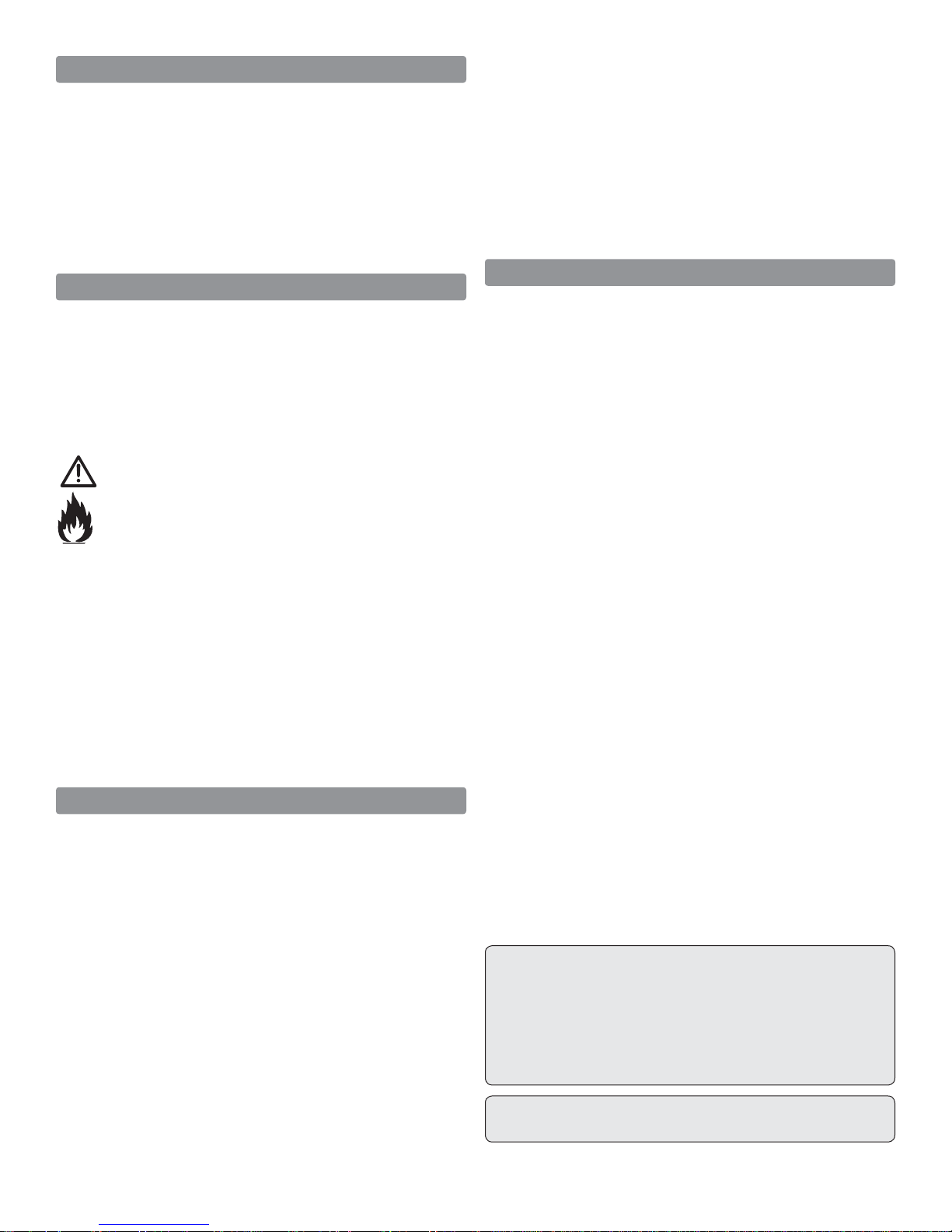
Installing the S.Bus System
Installation is actually simpli ed as compared to your normal
system installation. Using the S.Bus system you plug a battery
into the SBC-1 channel changing tool, using it to program
which channel you want the servo to operate on.
Once programmed, the
servo will operate as
required, regardless of
which lead it is plug ged into.
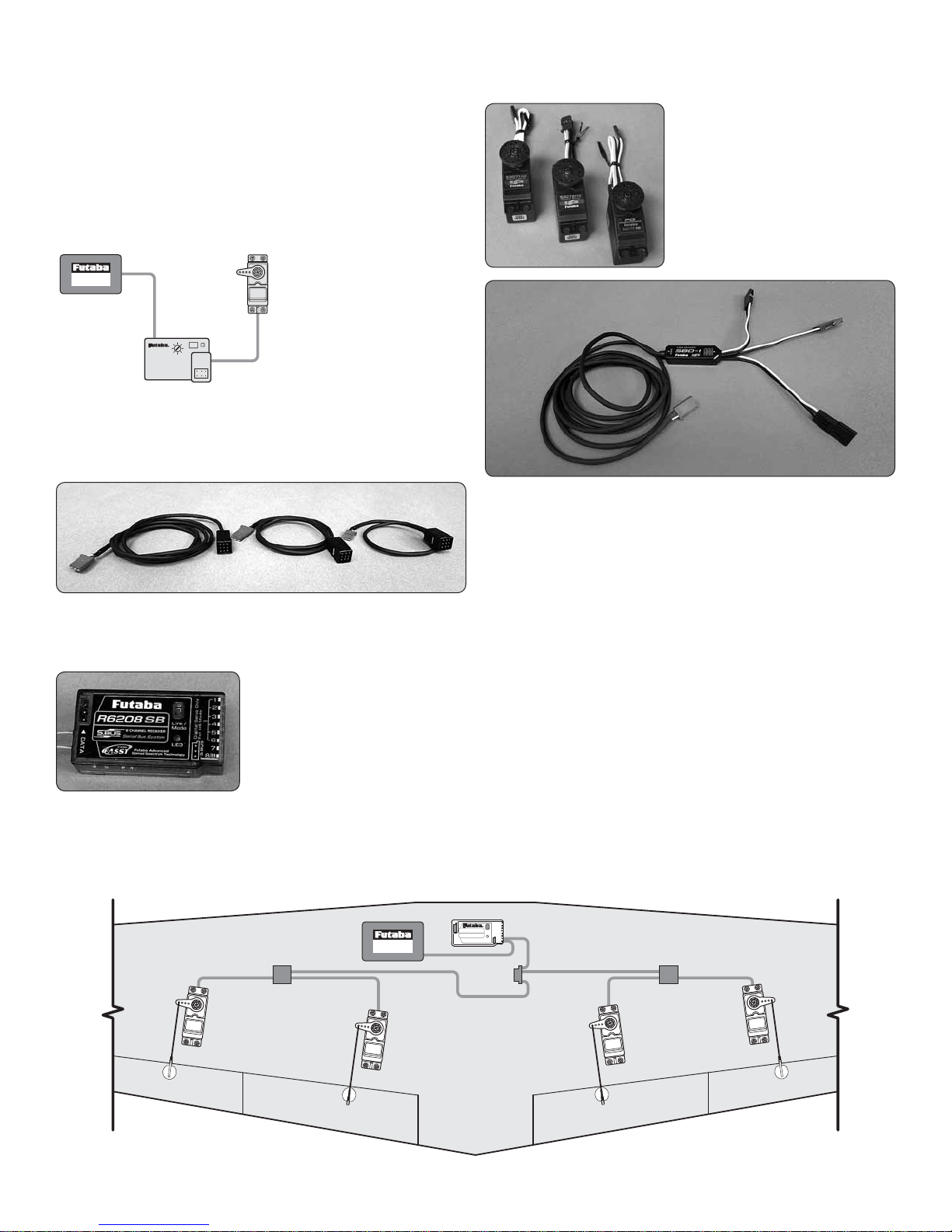
Do this for all of the servos
that you want to operate on
the S.Bus system. Install
the servos in the airplane
and plug them into the S.Bus lead, piggybacking them one
onto another. Once completed, you plug one lead into the
receiver for all of the servos and all of the servos will function
as programmed. One lead operates up to 16 servos!
S.Bus leads are available in a number of different lengths to
accommodate installation into any size airplane, regardless
of its complexity.
There are many choices for the
S. Bus receivers; some are tiny
3-port receivers with others
being up to 18 channels. The 8
PWM outputs can be used as
you would normally set up a
model, allowing you to split the
model and have some of it set up as S.Bus while other servos
are not using the S. Bus system. Something else to note is
that some of the S. Bus servos and receivers are HV, or High
Voltage, meaning that you could run a straight 2S LiPo for
your receiver battery.
Many servo choices are
available for use in a wide variety
of aircraft from micros to the
largest models.
Your system is not limited to programming only through the
SBC-1 channel changing tool and your transmitter. Utilizing the
USB interface, the CIU-2, you can do all of the programming
using your PC. Programming with this interface gives more
exibility and programming options than can be achieved
with any other radio system. To utilize standard, non-S.Bus
servos, you simply use the S.Bus decoder instead of the
S.Bus lead.
S.Bus System Set-up (using standard servos)
This set-up allows the use of non S.Bus servos. The retract
servo (or controller for electric retracts), optional drop tank
and optional receiver controlled lights are plugged directly
into the receiver.
NOTE: See the included layout drawing for required servos,
servo extension, S.Bus hubs and S.Bus Decoders. This
set-up will also require a SBC-1 S.Bus Channel Setting Tool
(FUTM4190) or CIU-3 USB Interface (FUTM0953) to program
the S.Bus decoders.
S.BUS SYSTEM
WING
Battery
Hub
Servo Servo ServoServo
S.Bus Receiver
Hub
Hub
6
Page 7

S.Bus System Set-up (using S.Bus servos)
This set-up uses programmable S.Bus servos. The retract
servo (or controller for electric retracts), optional drop tank
and optional receiver controlled lights are plugged directly
into the receiver.
NOTE: See the included layout drawing for required servos,
servo extension and S.Bus hubs. The S.Bus servos can be
programmed from some of the Futaba transmitters (see
the instruction manual included with your transmitter), the
SBC-1 S.Bus Channel Setting Tool (FUTM4190) or CIU-3
USB Interface (FUTM0953).
Retractable Landing Gear
The Top Flite Giant F6F Hellcat ARF has been designed for
Robart pneumatic and electric main and tail gear retracts.
Following is the complete list of items required to install the
Robart retracts:
Pneumatic Retracts
❍ (1) Robart #150-W 100 Degree Pneumatic Rotating
White Main Gear (ROBQ1675)
❍ (1) Robart #160WC-W Pneumatic White Fork Tail
Wheel Retract (ROBQ1677)
❍ (1) Robart #157VRX Large-Scale Deluxe Air Control
Kit – includes pressure tank, air line tubing, variablerate air valve, T- ttings (ROBQ2305)
❍ (1) Robart #169 10' [3048mm] red & purple Pressure
tubing (ROBQ2369)
❍ (1 pkg.) #190 Air Line Quick Disconnects
(ROBQ2395)
❍ (1) Futaba S3004 Standard Servo (FUTM0004)
❍ (1) Robart #164E Rechargeable Electric Air Pump
❍ Robart TFF6FCOMBO Main and Tail Wheel Retract,
White Mains and Tail Wheel and Tires Combo
Pneumatic Hellcat ROBQ1685
❍ Robart TFF6FCOMBO-E Main and Tail Wheel
Retract, White Mains and Tail Wheel and Tires, (1) 36"
(915mm) Extension, (1) 24" (610mm) Extension and
(2) 12" (305mm) Extension Combo Electric Hellcat
(ROBQ1686)
ADDITIONAL ITEMS REQUIRED
Required Hardware and Accessories
In addition to the items listed in the “Decisions You Must Make”
section, following is the list of hardware and accessories
required to nish the Top Flite Giant F6F Hellcat ARF. Order
numbers are provided in parentheses.
❍ Optional Black paint for the plywood radial engine
frame
❍ Propeller and spare propellers suitable for your gas
engine or motor
❍ Painted Pilot: We used the 1/5 Scale pilot from Best
Pilots at www. Bestpilots.typepad.com
❍ (2) Y-Harness Futaba (FUTM4135)/Tactic (TACM2751)
for the lights
❍ (1) Optional Futaba CPS-1 Channel Power Switch
(FUTM0940) to switch the lights on/off using a switch
on your transmitter
❍ (1) 10" [254mm] long, 7/64" Ball-end Hex Wrench
OR
❍ (1) 7/64" Ball-end Hex Wrench (GPMR8003) plus
(1) 5/32" x .014 Round Brass Tube K&S #8128
(K+SR8128) (See page 38)
Electric Retracts
❍ (1) Robart #150E-W 100 Degree Electric White
Rotating Main Gear (ROBQ1676)
❍ (1) Robart #160WCE-W Electric White Fork Tail
Wheel Retract (ROBQ1678)
❍ (1) Robart #177E12S 12" (305mm) Actuator Extension
(ROBM0178)
❍ (1) Futaba 8" Servo Extension (FUTM4140) or Tactic
6" Servo Extension (TACM2701)
Retract Options
❍ Robart 13850F6F White Aluminum Main Wheel/Hub
5.0" Hellcat (ROBQ1679)
❍ Robart 138BF6F316 White Aluminum Tail wheel/Hub
2.0" 3/16" Axle Hellcat (ROBQ1680)
❍ Robart TF150F6FCOMBO Main Retracts and
Tail Wheel Retract Combo Pneumatic Hellcat
(ROBQ1682)
❍ Robart TF150F6FCOMBO-E Main Retracts and Tail
wheel Retract, (1) 36" (915mm) Extension, (1) 24"
(610mm) Extension and (2) 12" (305mm) Extension
Combo Electric Hellcat (ROBQ1683)
❍ Robart TFF6FWHEELCOMBO White Aluminum
Main and Tail wheel Tire and wheel Combo Hellcat
(ROBQ1684)
Adhesives and Building Supplies
This is the list of Adhesives and Building Supplies that are
required to nish the Giant F6F Hellcat ARF.
❍ 1/2 oz. [15g] Pro Thin CA (GPMR6001)
❍ 1/2 oz. [15g] Pro Medium CA (GPMR6007)
❍ Pro 30-minute epoxy (GPMR6047)
❍ Pro 6-minute epoxy (GPMR6045)
❍ Threadlocker thread locking cement (PAAR2242)
❍ Mixing sticks (50, GPMR8055)
❍ Mixing cups (GPMR8056)
❍ Epoxy brushes (6, GPMR8060)
❍ Denatured alcohol (for epoxy clean up)
❍ PT-56 canopy glue (PAAR3300)
❍ Milled berglass (GPMR6165)
❍ Masking tape
❍ Drill
❍ Drill bits: 1/16" [1.5mm], 5/64" [2mm], 3/32" [2.5 mm],
1/8" [3 mm], 3/16" [4.5 mm], 13/64" [5mm], 5/16
[8mm], 1/2" [13mm]
❍ Small metal le
❍ Stick-on segmented lead weights (GPMQ4485)
❍ Silver solder w/ ux (STAR2000)
❍ Hobbico Soldering Iron 60 Watt (HCAR0776)
7
Page 8
❍ Revell #1 Light Duty Aluminum Handle Knife w/Blade
and Safety Cap (RMXR6903)
❍ Revell #11 Light Duty Blades (5-pack, RMXR6930)
❍ Sanding tools and sandpaper assortment
❍ Curved-tip canopy scissors for trimming plastic
parts (HCAR0667)
❍ Hex wrench SAE (HCAR0520)
Covering tools
❍ Top Flite MonoKote sealing iron (TOPR2100)
❍ Top Flite Hot Sock iron cover (TOPR2175)
❍ Top Flite MonoKote trim seal iron (TOPR2200)
❍ Top Flite MonoKote heat gun (TOPR2000)
Optional Supplies and Tools
Here is a list of optional tools mentioned in the manual that
will help you build the Giant F6F Hellcat ARF.
❍ 2 oz. [57g] spray CA activator (GPMR6035)
❍ CA applicator tips (HCAR3780)
❍ CA debonder (GPMR6039)
❍ Scale Warbird Template (TOPR2187)
❍ 36" metal ruler
❍ Hobbico High Precision Diagonal Cutter 5"
(HCAR0630)
❍ Pliers with wire cutter
❍ Robart Super Stand II (ROBP1402)
❍ Panel Line Pen (TOPQ2510)
❍ Rotary tool such as Dremel
❍ Rotary tool reinforced cut-off wheel (GPMR8200)
❍ Servo horn drill (HCAR0698)
❍ AccuThrow De ection Gauge (GPMR2405)
❍ CG Machine™ (GPMR2400)
❍ Precision Magnetic Prop Balancer (TOPQ5700)
● Replacement covering for the F6F Hellcat
Flat White (TOPQ0504)
Flat Insignia Blue (TOPQ0507)
Flat Medium Blue (TOPQ0517)
MODEL INSPECTION
Before starting to build, take an inventory of this model to
make sure it is complete, and inspect the parts to make
sure they are of acceptable quality. If any parts are missing
or are not of acceptable quality, or if you need assistance
with assembly, contact Product Support. When reporting
defective or missing parts, use the part names exactly as
they are written in the instruction manual.
Top Flite Product Support Ph: (217) 398-8970, ext. 5
3002 N Apollo Drive, Suite 1 Fax: (217) 398-7721
Champaign, IL 61822
E-mail: airsupport@top- ite.com
ORDERING REPLACEMENT PARTS
Replacement parts for the Top Flite Giant F6F Hellcat ARF
are available using the order numbers in the Replacement
Parts List that follows. The fastest, most economical service
can be provided by your hobby dealer or mail-order company.
Not all parts are available separately (an aileron cannot be
purchased separately, but is only available with the wing kit).
Replacement parts are not available from Product Support,
but can be purchased from hobby shops or mail order/Internet
order rms. Hardware items (screws, nuts, bolts) are also
available from these outlets.
To locate a hobby dealer, visit www.top- ite.com and click
on “Where to Buy”. Follow the instructions provided on the
page to locate a U.S., Canadian or International dealer.
IMPORTANT BUILDING NOTES
● Anytime a sheet metal screw is installed in wood, rst
install the screw, remove the screw and apply a couple of
drops of thin CA in the hole to harden the threads. After
the CA has cured, reinstall the screw.
● Photos and sketches are placed before the step they
refer to. Frequently you can study photos in following steps
to get another view of the same parts.
● You will see this symbol anytime cyanoacrylate
glue is required.
.
● You will see this symbol anytime a threaded
screw or nut is installed.
● You will see this symbol anytime
epoxy is recommended.
● Anytime a hole needs to be drilled you will see
this symbol with the recommended size drill bit.
REPLACEMENT PARTS LIST
Order No. Description
TOPA1980
TOPA1981
TOPA1982
TOPA1983
TOPA1984
TOPA1985
TOPA1986
TOPA1987
TOPA1988
TOPA1989
TOPA1990
TOPA1991
TOPA1992
TOPA1993
TOPA1994
TOPA1995
TOPA1996
TOPA1997
TOPA1998
TOPA1999
Fuselage Parts Set
Wing Set
Horizontal Stabilizer Parts Set
Rudder
Cowl
Canopy
Gear Doors
Dummy Engine
Antennas
Belly Pan
Tail Gear Cover
Hatch
Cockpit Kit
Drop Tank Complete
Drop Tank Only
Drop Tank Release
Pitot Tube
Wingtip Lens
Light Set
Decals
8
Page 9
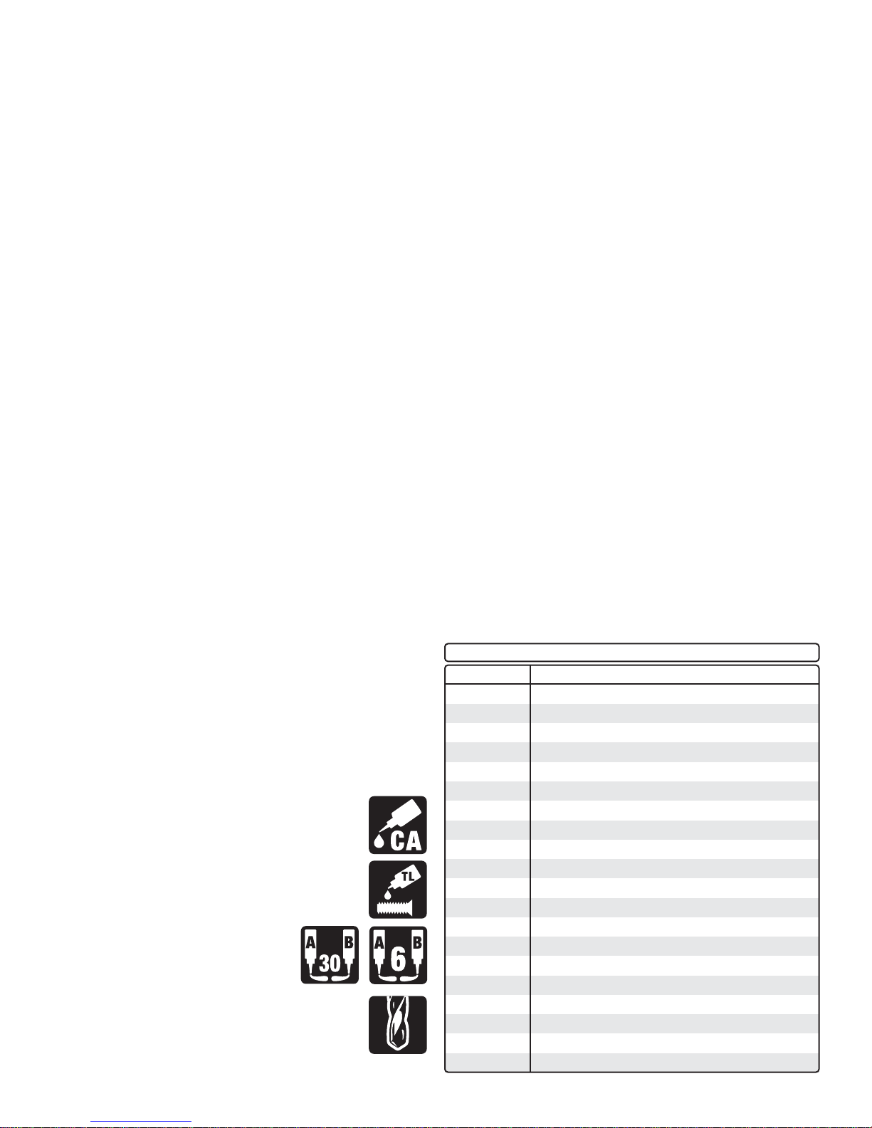
CONTENTS
1
4
20
21
22
23
24
17
18
19
25
26
16
6
7
27
2
5
14
28
15
13
8
ASSEMBLE THE WINGS
Important: If you remove all the parts from the plastic
bags, save the plastic bag the cowl comes in. This bag
will be used later when the cowl is installed.
Start with the left wing so the assembly matches the photos
the rst time through.
3
10
12
9
1. Cowl
2. Fuselage
3. Rudder
4. Right Wing Panel
5. Left Wing Panel
11
6. Belly Pan
7. Center Wing Panel
8. Right Stabilizer
9. Left Stabilizer
10. Landing Gear Covers
11. Tail Gear Cover
12. Dummy Engine Ring
13. Cowl Ring
14. Main Wheels
15. Tail Wheel
16. Can opy
17. Left Cockpit Side
18. Right Cockpit Side
19. Cockpit Floor
20. Seat
21. Instrument Panel
22. Cockpit Ar more
23. Rudder Pedals
24. Dummy Engine
25. Spinner Back Plate
26. Spinner Cone
27. Stabilizer Tubes
28. W ing Tube
1. If necessary, use a covering iron with a covering sock
❏
to go over the wing, ap and aileron to remove any wrinkles.
The best method to remove the wrinkles is to glide the iron
over the covering until the wrinkles disappear, then go over
the area again, pushing down on the iron to bond the covering
to the wood. If the wrinkles don’t disappear, the balsa in that
area might be exing inward. If this is happening, don’t press
down. Simply let the heat of the iron shrink the covering. If the
wrinkles momentarily disappear, then immediately reappear,
the iron may be too hot, thus causing air bubbles. Lower the
temperature of the iron or use a sharp #11 blade or T-pin
to puncture several holes in the covering, then reheat. The
suggested iron temperature is around 360 degrees F.
The Grumman F6F Hellcat went from test models to
combat in less than 18 months. Grumman built a total of
12,275 F6F Hellcats. It rst saw combat in August 1943 in
an attack on Marcus Island. The F6F Hellcat was credited
with destroying 5,223 aircraft. It had a kill-to-loss ratio
of 19:1 with the U.S. Navy/Marine Corps. The F6F Hellcat
was considered one of the best ghters of WWII.
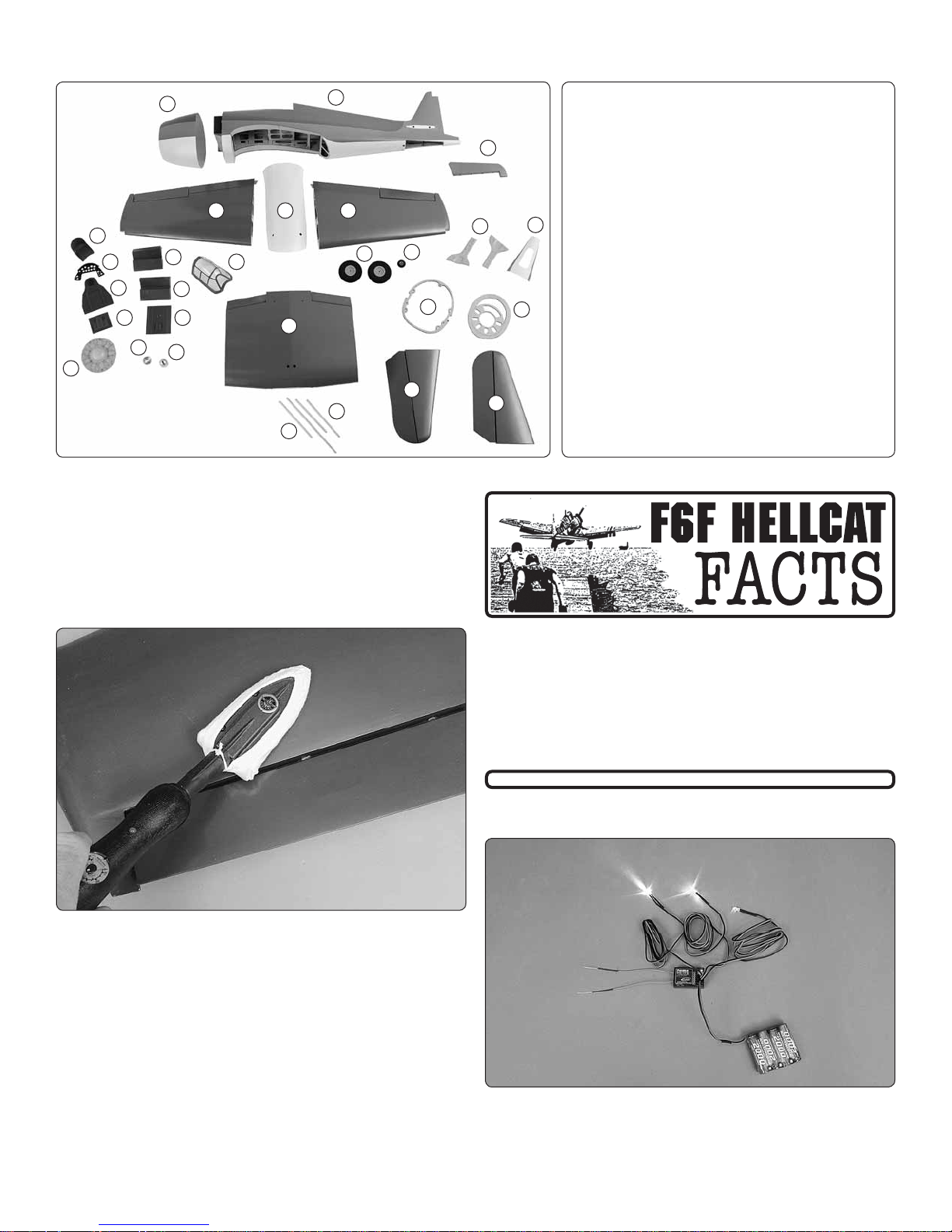
Install the Wing Tip Light
1. The red LED will be installed in the left outer wing panel.
❏
Using a 4.8 volt receiver battery and receiver, plug each LED
into the receiver. Plug the receiver battery into the receiver.
Use a piece of masking tape to identify the LED color.
9
Page 10
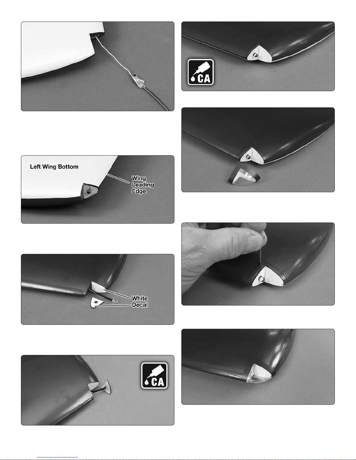
2. Tie the end of the string from the wing tip light recess
❏
to the plug of the red LED. Secure the string with a piece of
masking tape.
3. Pull the wire through the wing until the connector exits
❏
the root of the wing panel.
4. Insert the LED in one of the plywood LED supports.
❏
Position the support in the light recess so that it matches
the shape of the wing leading edge.
7. Glue the LED support in the wing tip.
❏
8. Last chance to test the red LED to make sure it is
❏
working and is the correct color. Position the wing tip lens
over the LED and mark the outline of the lens on the wing.
5. Attach the white wing tip light decal on the front of the
❏
LED support and the adjacent side of the wing tip light recess.
The LED support can also be painted white.
6. Glue the red LED in the hole in the plywood LED support.
❏
9. Use a T-pin to poke holes in the covering inside the
❏
lens outline.
10. Wipe off the outline and glue the lens to the wing tip
❏
with canopy glue.
11. Go back to step 1 and install the green LED in the
❏
right outer wing panel.
10
Page 11
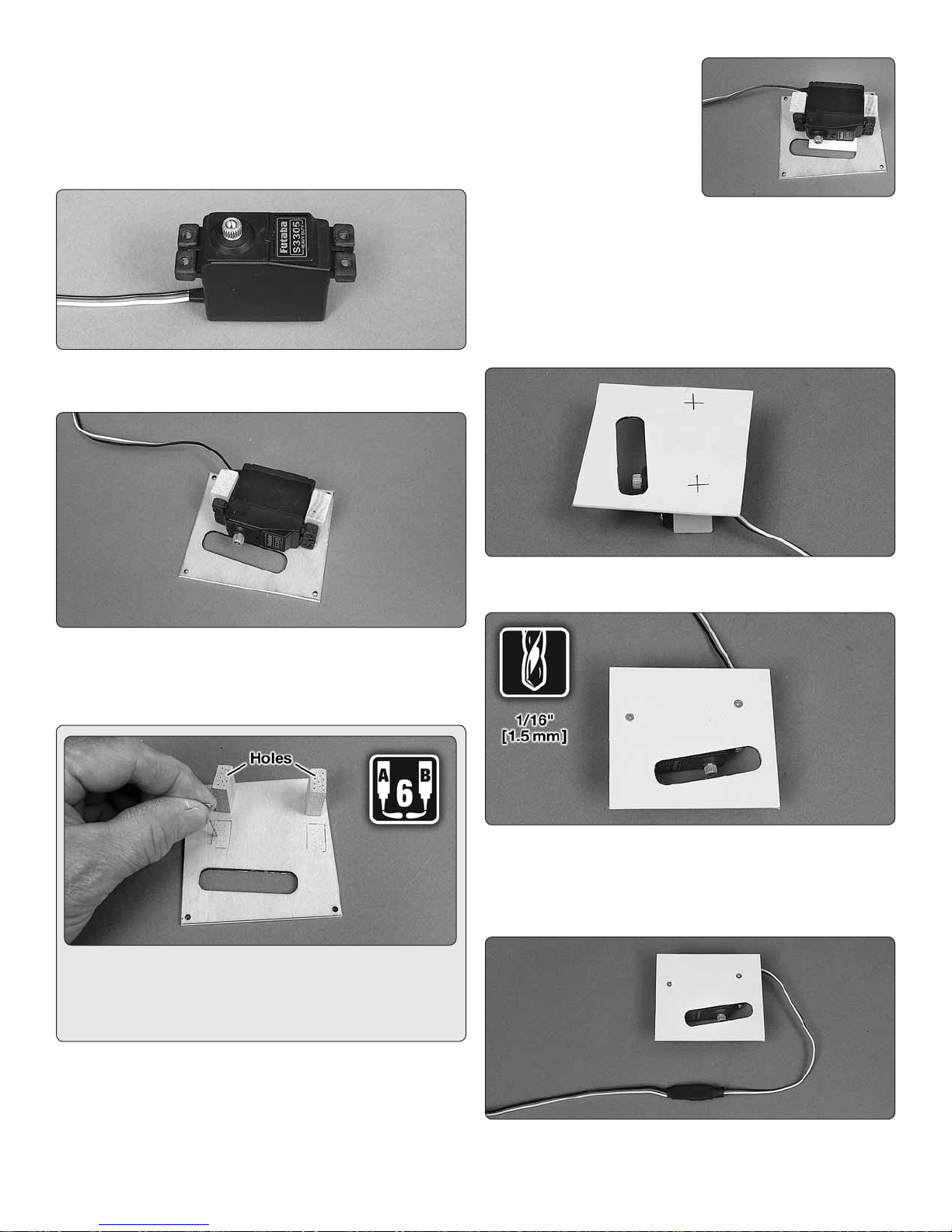
Install the Flap Servo
1. Carefully remove the left ap servo hatch from the
❏ ❏
wing by peeling off the masking tape holding the hatch to
the wing. Use a paper towel dampened with lighter uid
(CAUTION: Very Flammable) or similar solvent to remove
any glue left behind from the tape.
2. Install the rubber grommets and metal eyelets in
❏ ❏
the ap servo.
5. Once the epoxy has
❏ ❏
cured, remove the clamps.
Place a 1/16" [1.6mm] spacer,
such as a piece of cardstock
or a piece of paper folded
several times, under the servo
and between each mounting
block to raise the servo off the
servo hatch. After the servo is installed the spacer will be
removed, providing adequate spacing for vibration isolation.
6. Drill 1/16" [1.5 mm] holes through the blocks for the
❏ ❏
servo mounting screws. Mount the servo to the blocks with
the screws that came with the servo. Remove the servo
mounting screws and apply a couple of drops of thin CA in
each hole to harden the threads. Allow the CA to fully harden.
Then, reinstall the screws and remove the spacer.
3. Center the servo arm spline of the ap servo in the
❏ ❏
opening of the servo hatch cover. Position the two 7/8" x 5/8"
x 3/8" [20 x 15 x 8mm] hardwood blocks as shown and mark
the locations on the hatch cover.
To increase the strength of the glue joint, use a T-pin to
prick holes into the gluing surface of the servo blocks and
the plywood servo hatch. Be careful to not prick holes
completely through the servo hatch and covering.
7. Make two marks on the top of the servo hatch,
❏ ❏
centered on the two ap servo mounting blocks.
8. Drill 1/16" [1.5 mm ] holes through the servo hatch
❏ ❏
and into the servo blocks at the two previously made marks.
Install two #2 x 3/8" (9.5mm) self-tapping at head screws to
secure the servo mounting blocks to the aileron servo hatch.
Use thin CA to harden the screw threads.
4. Use 6-minute epoxy to glue the two blocks to the
❏ ❏
bottom of the servo hatch over the servo block locations.
Thoroughly coat the end of the blocks and allow them to set
for a few seconds to allow the blocks to absorb the epoxy.
Then, recoat the blocks. Use clamps to hold the blocks to
the servo hatch.
9. Following your radio setup diagram, connect the
❏ ❏
appropriate servo extension to your ap servo. Cut a piece
11
Page 12
of the supplied heat shrink tubing in half and slide it over
the servo connections. Shrink the tubing by applying heat
to the tubing.
10. If installing the S.Bus setup, connect the S.Bus
❏ ❏
decoder or S.Bus hub to the ap servo extension. Secure
the connection with a piece of heat shrink tubing if installing
the S.Bus decoder.
NOTE: If installing the Non S.Bus setup, follow the instructions
included with the SBC-1 S.Bus Channel Setting Tool
(FUTM4190) or CIU-3 USB Interface (FUTM0953) to program
the decoder. We set ap number 1 to channel 7.
13. Place the ap servo hatch with the servo in the wing.
❏ ❏
Be certain that the hatch is positioned correctly as shown.
Secure the hatch using four #2 x 3/8" [9.5mm] at head sheet
metal screws. Use thin CA to harden the screw threads.
Install the Aileron Servo
11. Plug the ap servo and receiver battery into the
❏ ❏
receiver. Switch on the transmitter and center the servo
trims. Temporarily install a servo arm on the ap servo, 60
degrees from the centerline of the servo. Test the movement
for the correct direction.
12. Use the string in the wing to pull the ap wires
❏ ❏
through to the aileron servo hatch location.
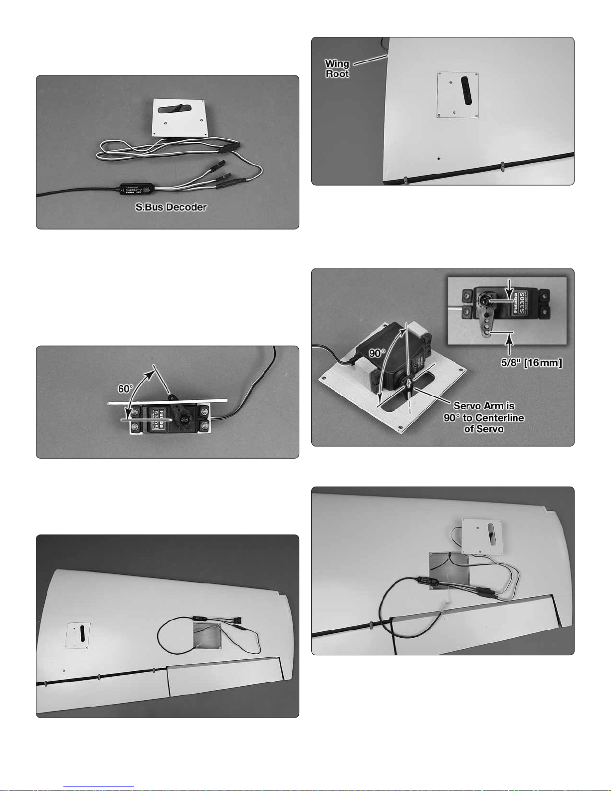
1. Install the aileron servo on the aileron servo hatch
❏ ❏
following the same method used to install the ap servo.
2. Following your radio setup diagram, connect the
❏ ❏
appropriate servo extension to your aileron servo. Or, plug
the aileron servo into the S.Bus decoder or hub. Secure the
connectors with a piece of heat shrink tubing.
Note: We set aileron number 1 to channel 5 in the S.Bus setup.
3. Use the string in the wing to pull the ap and aileron
❏ ❏
extensions or S.Bus decoder or hub through the wing.
12
Page 13
4. Secure the aileron hatch to the wing using four #2
❏ ❏
x 3/8" [9.5mm] at head sheet metal screws. Use thin CA to
harden the screw threads.
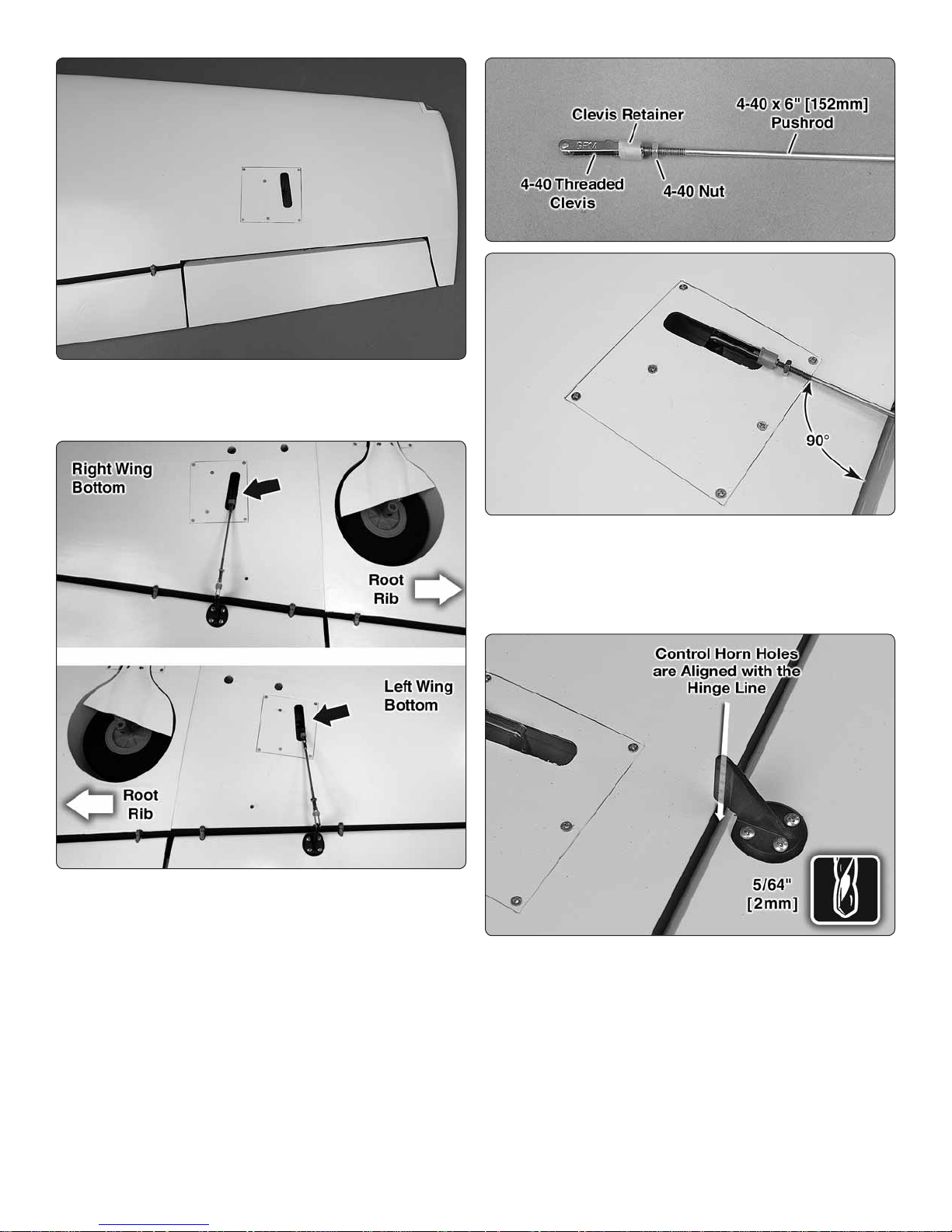
1. Slide a silicone clevis retainer over a 4-40 threaded
❏ ❏
metal clevis. Thread a 4-40 nut followed by the 4-40 metal
clevis, threaded 16 turns onto a 4-40 x 6" [152mm] metal
pushrod. Attach the clevis to the aileron servo arm 5/8"
[16mm] from the center of the arm.
5. Go back to step 1 on page 11 and install the right
❏ ❏
ap and aileron servos following the same procedure. The
left and right wing ap servos face the same direction.
NOTE: If installing S.Bus, we put the right wing ap #2 on
channel 8 and right aileron #2 on channel 6.
Install the Aileron and Flap Pushrods
Do the left aileron rst. Temporarily plug the aileron servo
into the receiver. Switch on the transmitter and plug a receiver
battery into the receiver. Center the aileron trim and adjust the
aileron servo arm so that it is perpendicular to the centerline
of the servo.
2. Position the control horn so that it is in line with the
❏ ❏
pushrod and over the plywood mounting plate. The holes
in the control horn should be aligned with the hinge line of
the aileron. On the aileron, mark the four mounting holes.
Remove the control horn and drill a 5/64" [2mm] pilot hole at
each mark. Do not drill completely through the aileron. Attach
the control horn using four #4 x ½" sheet metal screws. Use
thin CA to harden the holes.
13
Page 14
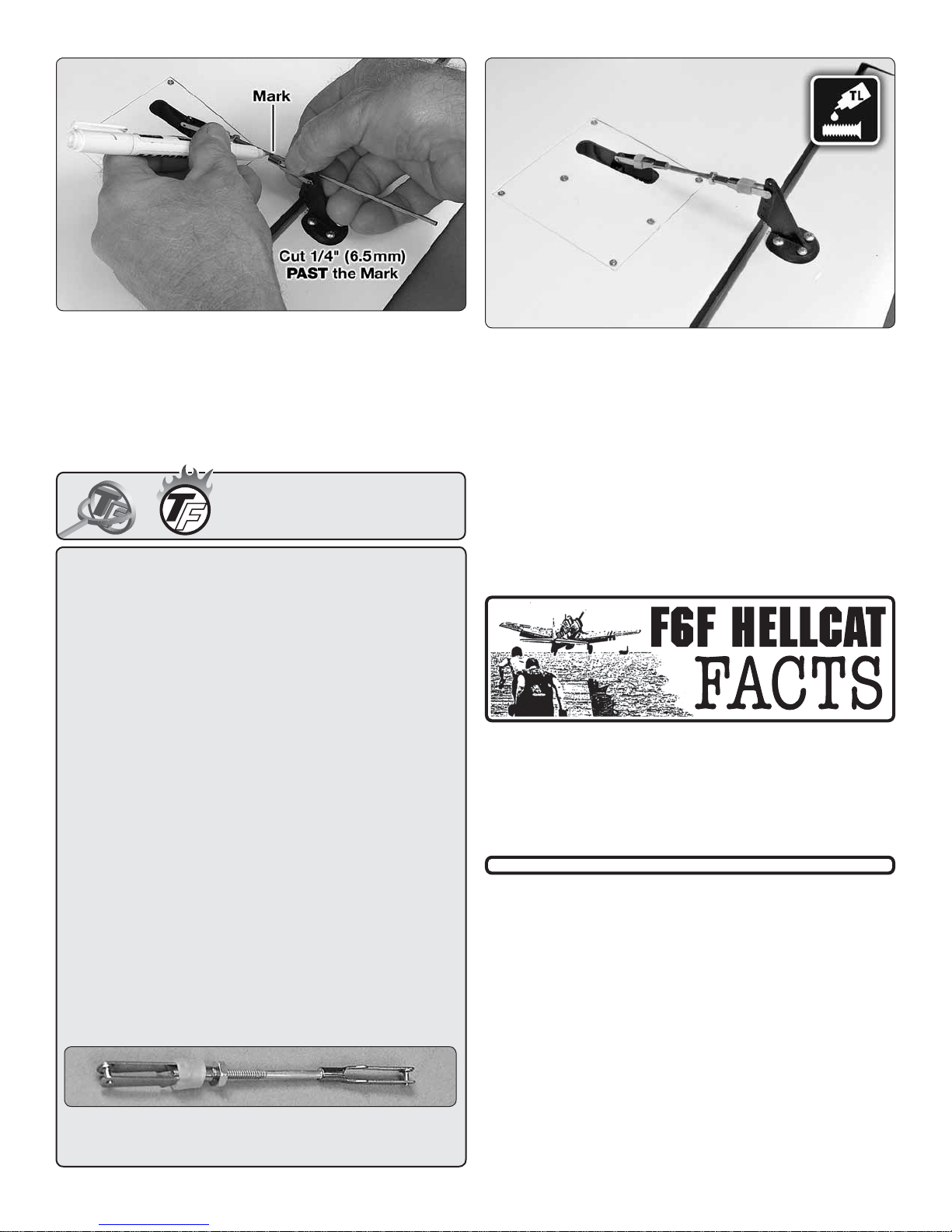
3. Install the metal solder clevis in the 2nd hole from
❏ ❏
the outer end of the control horn. Center the aileron servo
and aileron. Mark the pushrod where it meets the solder
clevis. Remove the pushrod and the solder clevis and cut
the pushrod 1/4" [6.5mm] past the mark. Solder the solder
clevis to the pushrod using the techniques described in the
following Hot Tip.
Hot Tip
HOW TO SOLDER
1. Use denatured alcohol or other solvent to thoroughly
clean the pushrod. Roughen the end of the pushrod with
coarse sandpaper where it is to be soldered.
2. Apply a few drops of soldering ux to the end of the
pushrod. Then, use a soldering iron or a torch to heat it.
“Tin” the heated area with silver solder by applying the
solder to the end. The heat of the pushrod should melt the
solder – not the ame of the torch or soldering iron – thus
allowing the solder to ow. The end of the wire should be
coated with solder all the way around.
3. Place the clevis on the end of the pushrod. Add another drop of ux. Then, heat and add solder. The same
as before, the heat of the parts being soldered should
melt the solder, thus allowing it to ow. Allow the joint to
cool naturally without disturbing. Avoid excess blobs, but
make certain the joint is thoroughly soldered. The solder
should be shiny, not rough. If necessary, reheat the joint
and allow to cool.
4. Immediately after the solder has solidi ed, but while it
is still hot, use a cloth to quickly wipe off the ux before
it hardens. Important: After the joint cools, coat the joint
with oil to prevent rust. Note: Do not use the acid ux that
comes with silver solder for electrical soldering.
4. Slide a silicone clevis retainer over the solder clevis.
❏
Reinstall the aileron pushrod with the threaded clevis attached
to the control horn. Adjust the threaded clevis so that the
aileron is centered. Apply a drop of thread locker to the
threads of the pushrod behind the clevis. Tighten the 4-40
nut against the clevis.
5. Assemble and connect the ap pushrods following
❏
the same procedure. We installed the pushrod in the outer
hole of the control horn and the hole 5/8" [16mm] from the
center of the servo arm.
6. Return to step 1 and install the aileron and ap pushrods
❏
on the right wing.
The F6F Hellcat was tted with the 2,100 hp Pratt &
Whitney R-2800-10W engine, the same engine used in
the Corsair and the P-47 Thunderbolt. It had a gross
weight of 15,413 lbs. Its maximum speed was 376 mph
at 23,400 ft. It carried six 50-caliber machine guns with
400 rounds of ammunition.
This is what a properly soldered clevis looks like – shiny
solder with good ow, no blobs and ux removed.
14
Page 15
Mount the Retracts
Install the left retract rst.
3. Tie the Actuator extension or pressure lines along with
❏
a ap and aileron servo extension or S.Bus hub, depending
on your setup, and a 16" (400 mm) servo extension for the
wing tip lights to the string in the retract bay. Pull the lines
out the hole in the top of the wing and tape them to the top
of the wing.
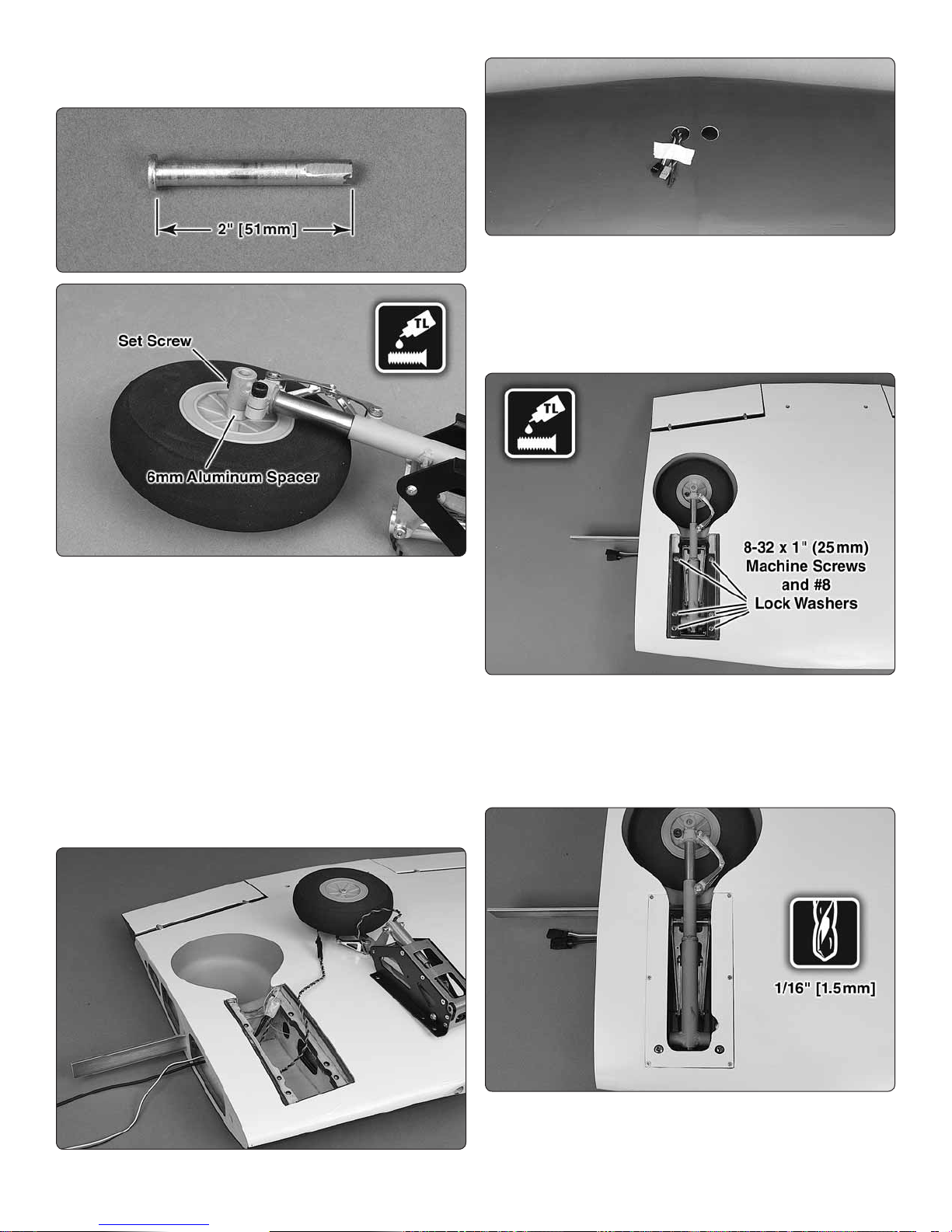
1. Trim the a xle that is included with the Robart retracts to
❏
2" [51mm] long. File a at spot at the end of the axle. Insert
the axle through the included 5" [127mm] wheel. Slide the
6mm thick aluminum wheel spacer onto the axle. Insert the
axle into the retract. Apply a drop of threadlocker to the 1032 x 3/16" [4.8mm] set screw, included with the retract, and
tighten the set screw onto the at of the axle. Make sure that
the wheel rotates freely.
2. Connect a 12" (305mm) Actuator Extension (included
❏
with the retracts) to the retract. If installing pneumatic retracts,
attach the air lines to the retract.
4. Secure the retract in the wing with six 8-32 x 1" (25mm)
❏
machine screws and #8 lock washers. Before installing, apply
a drop of thread locker to the threads on the machine screws.
5. Operate the retract to make sure the wheel does not
❏
bind in the wheel well.
6. Position the retract cover over the retract and drill 1/16"
❏
(1.5mm) pilot holes using the holes in the cover as a guide.
Mount the cover to the wing with #2 x 3/8" (9.5mm) at head
screws. Harden the screw holes with thin CA.
15
Page 16
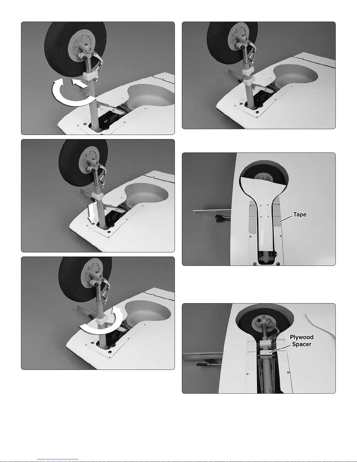
8. Install the second landing gear door mount and position
❏
as shown.
9. Retract the landing gear and position the landing gear
❏
door over the strut. Center the door in the opening. Place a
piece of masking tape on each side of the retract. Mark the
position of the mounting holes on the tape.
7. Extend the landing gear and snap one of the landing
❏
gear door mounts over the retract. Rotate the mount and
slide it up the strut past the pin.
10. Use the 1/16" (1.5mm) plywood spacers to adjust
❏
the height of the gear doors to match the bottom of the
wing. If one of the gear door mounts is too high, use 80 grit
sandpaper to sand the face of the mount. Once satis ed
with the height of the gear doors, glue the plywood spacers
to the gear door mounts.
16
Page 17
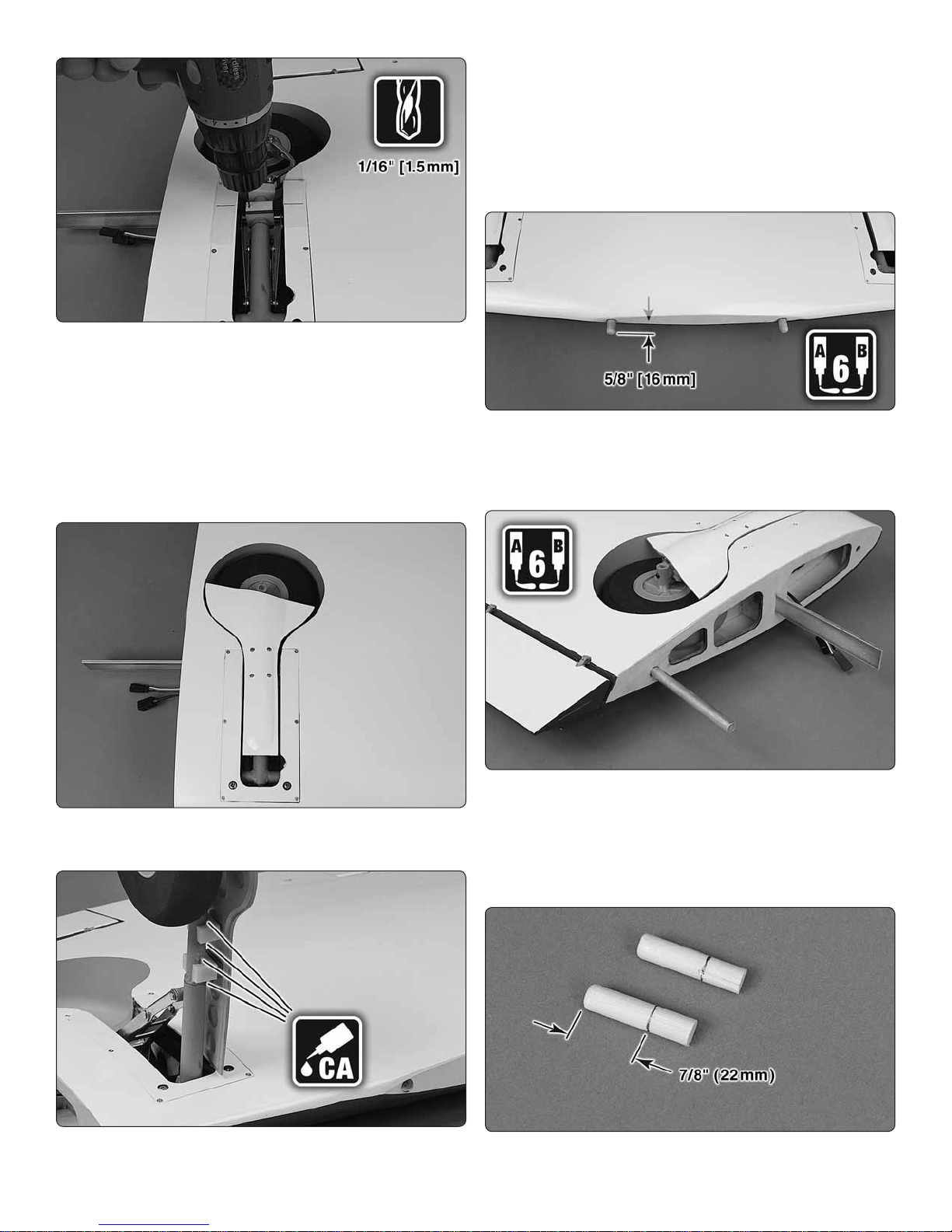
11. Center the gear door mounts and the mounting holes
❏
on the gear doors with the marks on the wing. Using one of
the mounting holes as a guide, mark the hole location on the
gear door mount. Remove the gear door. Drill a 1/16" (1.5mm)
pilot hole at the mark on the gear door mount.
12. Temporarily mount the gear door to the gear door
❏
mount with a #2 x ½" (12.5mm) sheet metal screw. Drill the
three remaining pilot holes using the holes in the gear door
as a guide.
apply a couple of drops of thin CA between the gear door
mount and the landing gear strut.
15. Go back to step 1 on page 15 of Mount the Retracts
❏
and install the right retract.
Join the Wing Panels
Note: Keep the retracts in the retracted (up) position.
1. Use 6-minute epoxy to glue the two 3/8 x 2-3/8" [10 x
❏
60mm] diameter forward wing dowels in the leading edge of
the wing. The wing dowels should protrude approximately
5/8" [16mm] from the wing.
13. Install the gear door with #2 x ½" (12.5mm) sheet
❏
metal screws.
14. Position the gear door on a strut in the opening and
❏
extend the landing gear. Without disturbing the gear door,
2. Test t the aluminum wing tubes in the wing center
❏
section. Use medium grit sandpaper to roughen up the part
of the tube that will be glued in the center section. Clean the
tubes with denatured alcohol. Glue the tubes in the wing
center section with 6-minute epoxy. Wipe off any excess
epoxy with a paper towel dampened with denatured alcohol.
3. Place a mark 7/8" ( 22mm) from the end of the 5/16 x
❏
1-3/8" (8 x 35mm) wing alignment dowels.
17
Page 18

7. Loosen the screws and remove the outer wing panel.
❏
The 4-40 socket head cap screws will have left a mark on
the aluminum blade. Use a metal le to cut a shallow 1/32"
(0.8mm) slot in the aluminum blade.
ASSEMBLE THE FUSELAGE
4. Use 6-minute epoxy to glue the wing alignment dowels
❏
in the forward hole of the wing outer panels. Before the epoxy
cures, slide the wing outer panel onto the wing center section.
Leave a small gap between the wing panels to avoid gluing
the wing panels together.
5. Once the epoxy has cured, slide the wing panels together
❏
completely. Locate and cut the covering from over the four
outer wing panel bolt holes, two on top and two on bottom.
6. Apply a drop of thread locker to the threads of four 4-40
❏
x ¼" (6mm) socket head cap screws. Install the screws and
#4 lock washers into the C-channel in the outer wing panel.
Tighten the screws against the wing joiner blade.
Install the Stabilizer
1. Test t the two aluminum stabilizer tubes in the fuselage
❏
and slide the stabilizers on the tubes. The shorter tube goes
in the front hole. If the aluminum tubes are too tight to slide
through the holes, take a sharp hobby knife and gently scrape
the inside of the holes. During the manufacturing process a
small amount of resin or ller may be left behind in the hole.
2. Test t the stabilizer halves. Once you are satis ed
❏
with the t of the stabilizer halves, remove the stabilizer
halves and the joiner tubes. Use medium grit sandpaper
to roughen up the aluminum tubes and the gluing surfaces
on the fuselage stabilizer roots. Clean the tubes and gluing
surfaces with denatured alcohol and insert both tubes back
into the fuselage until the end exits on the opposite side by
approximately 1" [25mm].
18
Page 19

3. Gather everything required for gluing the stabilizer halves
❏
to the fuselage including 30-minute epoxy, mixing sticks,
epoxy brush, 12" [304mm] long dowel or wire, masking tape,
denatured alcohol and small paper towel squares. Mix up 3/4
oz. [22.1cc] of 30-minute epoxy. Apply a generous amount
of epoxy to the long side of the aluminum joiner tubes. Pull
the tubes through the fuselage so that they are close to
centered. Pour a small amount of epoxy into both holes of
one of the stabilizer halves and using a dowel or wire, coat
the inside of the holes. Apply epoxy to the root rib of the
stabilizer and the fuselage. Insert the end of the aluminum
tubes with epoxy on them into the stabilizer and press the
stabilizer against the fuselage. Wipe off any excess epoxy
that may have squeezed out before it runs down the fuselage.
Quickly repeat the process on the other side. Wipe off any
excess epoxy with a dampened paper towel and denatured
alcohol. Use pieces of masking tape to hold the stabilizer
tight against the fuselage until the epoxy cures.
the pivot point of each hinge must align with the center of
the trailing edge. To achieve this alignment, the hinges will
be fairly deep in the n. Also note that the hinges must be
perpendicular to the trailing edge.
5. Again without glue, test t the rudder to the n. Move
❏
it left and right a few times to align the hinges. The rudder
doesn’t have to move very far, only 1-1/2" [38mm] left and
1-1/2" [38mm] right measured at the widest par t of the rudder
at the trailing edge. If there is too much resistance, or if you
are not able to move the rudder left and right 1-1/2" [38mm],
widen the gap slightly between the rudder and n.
4. Remove the nylon torque rod horn from the rudder
❏
torque rod. Insert the torque rod bearing in the n. Without
using any glue, install four hinges into the n. Note that
6. Remove the rudder, hinges and rudder torque rod.
❏
Apply a small drop of oil to both ends of the rudder torque
rod bearing. This will prevent epoxy from adhering to the
rudder torque rod. Use 6-minute epoxy to glue the rudder
torque rod bearing in the n.
7. Add a small drop of oil to the pivot point on the hinges.
❏
This will prevent the epoxy from adhering to the pivot point.
Make sure oil does not get on the gluing surface of the hinge.
If it does, clean the oil off with a paper towel dampened with
denatured alcohol.
19
Page 20

8. Mix up approximately ¼ oz. [7.4cc] of 30-minute epoxy.
❏
Use a toothpick to thoroughly apply the epoxy in the holes
in the n and rudder. Use the toothpick to get the epoxy out
of the opening of the holes in the rudder and n so it doesn’t
get into the hinge pin. Wipe away any excess epoxy around
the outside of the holes with a paper towel dampened with
denatured alcohol.
Install the Tail Light
9. Use the toothpick to apply epoxy to the ends of the
❏
rudder hinges that go into the n. Insert each hinge into the
n and wipe away any excess epoxy that squeezes out of
the hole.
10. Apply epoxy to the other end of the hinges. Join the
❏
rudder to the n, pushing the hinges only about ¾ of the way
into the rudder. Use a paper towel to wipe away any epoxy
that squeezes out. Then, t the rudder the rest of the way on.
11. Move the rudder left and right a few times to align the
❏
hinges and make certain that the rudder de ects left and
right the full 1-1/2" [38 mm].
Because of its variety of weapons and equipment the F6F
Hellcat was able to perform a broad range of missions.
This included ghter versus ghter, strike plane escort,
combat air patrol, long range search, ground support,
night ghting and photo recon.
1. Test t the tail light in the fuselage. We found that the
❏
wire from the LED is stiff enough to guide the LED to the
hole. However, it is not stiff enough to push the LED into the
hole. Once you have the LED positioned in front of the hole,
use the included white inner pushrod tube to push the LED
into the hole.
2. Now that you have the installation method down, apply
❏
a couple of drops of 6-minute epoxy to the LED base and
reinstall the LED.
3. Once the epoxy has cured, route the wires through the
❏
fuselage to the servo tray.
20
Page 21

Mount the Retractable Tail Gear
1. Remove the steering arm from the Robart #160WC
❏
retractable tail gear assembly (not included). File a at spot
near the top of the shaft for the set screw, in the steering
arm, to seat against. Re-install the steering arm on the shaft.
Apply a drop of threadlocker to the set screw and re-install
the set screw.
2. File another at spot near the bottom of the shaft for
❏
the set screw in the fork. Apply threadlocker to the set screw
and re-install. Check that the axle in the fork and the steering
arm are parallel with each other. Make adjustments to the
at spots if necessary.
5. Use wire cutters to cut the supplied braided cable into
❏
two equal lengths. Slide a swage (metal tube) over one end
of the cables. Then, guide the end of the cable back through.
6. Wrap the cable back around and through the swage.
❏
3. Enlarge the hole through the 1-3/4" (44mm) tail wheel
❏
with a #9 [5mm] drill bit. Install a 5mm metal spacer on each
side of the wheel. Re-install the tail wheel on the retractable
tail gear. Apply a drop of threadlocker to the threads of the
mounting screws.
4. Insert a .080" ball link ball in the middle hole of each arm.
❏
Secure each ball with a .080" nut and a drop of threadlocker.
7. Use pliers to pull the cable from the rst loop to reduce
❏
the size of the second loop.
8. Now pull on the long end of the cable to reduce the
❏
size of the rst loop. Slip the loop over one of the ball link
balls on the steering arm. Tighten the loop until it is small
enough to remain secure on the ball, yet may still be pried
off. Squeeze the swage with pliers. Connect the other cable
to the other ball link ball the same way.
9. Connect a 36" [915mm] actuator extension (included
❏
with retract) to the electric retractable tail gear or air lines to
the pneumatic retractable tail gear.
21
Page 22

10. Place the tail gear in the fuselage while simultaneously
❏
guiding the pull-pull cable through the white plastic guide
tubes. Also route the actuator extensions or air lines through
the fuselage.
11. Drill four 3/32" [2.5mm] holes through the rails for
❏
mounting the tail gear. If your drill bit is not long enough to
reach the rail nearest the top of the fuselage, use medium CA
to temporarily glue a 3/32" [2.5mm] drill bit in a 1/8" [3.2mm]
brass tube. After drilling the holes, the drill bit can be removed
from the tube by heating the tube.
INSTALL THE ELEVATOR
AND RUDDER SERVOS
1. If you are installing pneumatic retracts, insert the
❏
pressure tank in the fuselage. Apply a couple of dabs of
silicone glue to the joint between the tank and the former.
2. Use thin CA to glue the 1/8" x 3/8" x 5-3/4" [3.2 x 9.5
❏
x 146mm] plywood servo doublers to the bottom of the
servo tray.
3. If you are installing pneumatic retracts, glue the pressure
❏
tank retainer to the bottom of the servo tray.
22
Page 23

4. Insert the servo tray. Use the six holes in the servo tray
❏
as guides to drill 1/16" [1.5mm] pilot holes into the servo
tray frame. Secure the servo tray to the frame with #2 x 3/8
sheet metal screws and #2 at washers. Harden the screw
holes with thin CA.
5. Before reinstalling the servo tray, install the grommets
❏
and eyelets on the rudder, elevator and steering servos. Install
the servos as shown. Use thin CA to harden the screw holes.
7. Cut three 5" (127mm) long pieces of hook and loop
❏
strip, from one of the 24" (610mm) long hook and loop strips.
Overlap the strips by 1" (25mm). Wrap the receiver and
receiver battery in foam and secure them to the receiver
battery tray. Connect the receiver battery to the receiver
switch. NOTE: If installing S.Bus, skip to the next step.
Connect the switch to the battery port on the receiver. Secure
the battery to the switch connection with a piece of heat
shrink tubing.
6. Mount the receiver switch in the opening in the
❏
fuselage frame and through the fuselage side or mount
the switch in the position of your choice.
8. S.Bus Only: Install the 6-Way Terminal Box (not
❏
included) on the receiver battery tray. Connect the receiver
battery to the receiver switch. Plug in the receiver switch to
the terminal box. Connect a Male-to-Male extension from
the terminal box to the battery port on the receiver.
23
Page 24

and a silicone clevis retainer, 16 turns, onto both elevator
pushrods and the rudder pushrod.
9. Follow your radio setup diagram to connect the elevator,
❏
rudder and tail wheel steering to the receiver. Using S.Bus,
we plugged both elevator servos and the rudder servo into
one decoder and the tail wheel steering servo into a second
decoder. Set one of the elevators on channel 9, the other
on channel 10, the rudder on channel 11 and the tail wheel
steering on channel 12. Plug both decoders into the terminal
box. Secure the servo connections with heat shrink tubing.
12. Mount the control horns to the elevators the same way
❏
they were mounted on the ailerons, by drilling 3/32" [2.5mm]
pilot holes and using #4 x ½" [13mm ] sheet metal screws.
Use thin CA glue to harden the screw holes. Attach the
threaded clevis in the outer hole of the elevator control horn.
10. Switch on your transmitter and then the receiver. Center
❏
the elevator trims. Install a servo arm on both elevator servos
perpendicular to the centerline of the servo.
11. Insert the three 4-40 x 36" [915mm] metal pushrods in
❏
the elevator and rudder pushrod outer pushrod tubes at the
aft end of the fuselage. Thread a 4-40 nut, threaded clevis
13. Install solder clevises on the elevator servo arms in the
❏
hole 3/8" [9.5mm] from the center of the servo arm. Following
the same procedure that was done for the aileron and ap
pushrods, center the elevator and mark the elevator pushrods
where they are to be cut for the solder clevises. One at a time,
24
Page 25

remove the threaded metal clevis and nut from the control
horn end, remove the pushrod from the fuselage, cut it to the
correct length and solder a metal solder clevis on the end.
Reinstall the pushrod from the front and connect the solder
clevis to the servo arms. Reinstall the threaded metal clevis
and 4-40 nut. Apply a drop of thread locker to the threads
and tighten the nut against the clevis. Don’t forget to use
a silicone clevis retainer on all the clevises.
15. Thread a 4-40 nut and a 4-40 metal clevis, 12 turns,
❏
onto each of the 4-40 rigging couplers. Slide a silicone
clevis retainer over each clevis. Install the clevises on the
steering servo arm in the hole 5/8" [16mm] from the center
of the servo arm.
14. Install solder clevis on the rudder servo arm in the
❏
hole 5/8" [16mm] from the center of the servo arm. Thread
the nylon torque rod horn onto the rudder torque rod so that
it is 5/16" [8mm] from the fuselage side. Attach the clevis to
the torque rod horn, center the rudder, and mark the rudder
pushrod where it is to be cut for the solder clevis. Remove
the threaded metal clevis from the control horn end, remove
the pushrod from the fuselage, cut it to the correct length
and solder a metal solder clevis on the end. Reinstall the
pushrod from the front and connect the solder clevis to the
servo arms. Reinstall the threaded metal clevis and 4-40 nut.
Apply a drop of thread locker to the threads and tighten the
nut against the clevis. Again, use a silicone clevis retainer
on the clevises.
16. Lower the tail gear. Center the servo arm and the tail
❏
gear. Install a swage on each cable, securing it following the
same procedure used on the tail gear ball links. Use a pliers
to crimp the swage tightly on the cable.
17. The tail gear retract cover can be permanently installed
❏
using CA glue or with screws. If CA glue is used it will be
very dif cult to remove the cover and access the retracts if
needed. To install the cover with screws, tape three pieces
of paper on each side of the fuselage. Put one at each end
of the tail gear opening and one in the middle. Place marks
3/32" [2mm] from the edge of the opening, centered in the
balsa stringer.
25
Page 26

ELECTRIC MOTOR INSTALLATION
If you are powering the F6F Hellcat with a gas engine, skip
ahead to GAS ENGINE INSTALLATION on page 29.
1. The removable battery hatch is secured at the factory
❏
with two #2 x 3/8" [9.5mm] sheet metal screws. Remove the
two screws from inside of the fuselage. Using a sharp knife
blade, locate and carefully cut the battery hatch from the
fuselage. Extra Insignia Blue covering has been provided to
cover the edges of the hatch and the fuselage along the cut.
18. Position the tail gear retract cover over the opening,
❏
aligning the seam with the blue and white covering. Tape it
in place. Drill 1/16" [1.5 mm] holes through the cover and the
fuselage at each mark. Remove the cover and enlarge the
holes in the cover only with a 3/32" [2.5 mm] drill bit. Attach
the cover to the fuselage with #2 x 3/8" [9.5mm] sheet metal
screws and #2 washers. Harden the screw holes with thin
CA glue.
The aircraft maintenance of cers liked the F6F Hellcat
because it was a simple plane to maintain. It had very
little hydraulic system to break. The plane was based
on Roy Grumman’s motto “build it strong, keep it simple
and make it work.”
2. Install the plywood battery tray, aligning the slots and
❏
tabs. Check that the tray is seated on the formers and then
glue it in the fuselage.
3. Glue the plywood battery tray support to the aft end
❏
of the battery tray.
26
Page 27

4. Install the motor mount on the RimFire 65 motor following
❏
the instructions included with the XX-Large Stand Off Motor
Mount. The front of the drive washer should be 6-3/4" [171mm]
from the back of the stand offs.
6. Assemble the ESC mount as shown. Drill 5/64" [2mm]
❏
pilot holes through the doubler as shown.
5. Follow the Stand Off Motor Mount instructions to install
❏
the motor on the rewall box. The RimFire 65 motor uses the
embossed ‘X’ pattern on the front of the rewall box. Drill a
5/16" [8mm] hole at each mark.
7. Position the ESC mount on the rewall box and drill
❏
four 5/64" [2mm] pilot holes through the rewall box (two
on top and two in the front). Attach the ESC mount with #4
x ½" [13mm] sheet metal screws and #4 at washers. Apply
a drop of thin CA to harden the screw holes.
27
Page 28

8. Use a sharp hobby knife to open the slot in the bottom
❏
of the rewall box.
12. WITHOUT THE PROPELLER INSTALLED, check
❏
the rotation of the motor. Switch on the transmitter, then
receiver. Connect the Great Planes Series Connector to
both batteries and plug the Series Connector into the ESC.
Advance the throttle and check that the motor is rotating
counterclockwise. If it is not, switch two of the three bullet
connectors between the motor and ESC. We recommend
that an arming plug be installed. The Schumacher Products
ArmSafe arming kit works great.
If electric powered, skip to INSTALL THE
PNEUMATIC AIR VALVE CONTROLS on
page 33.
GAS ENGINE INSTALLATION
9. Solder the bullet and battery connectors on the ESC.
❏
Attach the ESC to the ESC mount with four #4 x ½" [13mm]
sheet metal screws and #4 at washers.
10. Connect a 6" to 8" [152mm to 203mm] long servo
❏
extension to the ESC. Plug the ESC into your receiver. If using
S.Bus with non S.Bus servos plug the ESC into a decoder.
We put the throttle on channel 13.
1. The rewall has two sets of engine mounting bolt
❏
patterns embossed on it. The “+” are for the DLE-55 Rear
Exhaust and DLE-61 Side Exhaust gas engines and the “X”
are for the DLE-55 Side Exhaust gas engines. In the back
of this manual we provide a paper template for mounting
the O.S. GT 60 gas engine. If you are installing an engine
with a different mounting bolt pattern, the rewall also has
crosshairs embossed on it to help center the engine.
11. Make two battery straps from the second strip of hook
❏
and loop material. Insert the straps in the battery tray. The
location of the batteries forward or aft will be determined
when the plane is balanced.
2. Drill a 13/64" [5mm] hole through the rewall at each of
❏
the appropriate locations marked with an “X” or “+”.
28
Page 29

3. Install the engine mounting bolts and fender washers
❏
from the back of the rewall. The engine mounting hardware
is not included in the F6F Hellcat. It should be included with
the engine. If your engine did not include fender washers,
we recommend purchasing them. The larger washers (1/2"
[12 mm] or larger) will help distribute the load from the engine.
Apply a drop of thread locker to each bolt before installing
them in the engine standoffs. For a reference, once the engine
is installed, the front of the engine drive washer should be
6-3/4" [171mm] from the front of the rewall.
5. Temporarily install the engine inverted on the aluminum
❏
standoffs.
6. Snap a nylon ball socket onto both pivot balls. Center
❏
the choke and throttle arms and mark the rewall where the
pushrods will need to pass through. Also mark the location
where the fuel line will need to pass through the rewall.
4. Install a 2-56 ball link ball on the throttle arm and the
❏
choke arm and secure them with a 2-56 nylon locknut. Also
make sure the throttle arm is positioned as shown. Apply
thread locker to the screw before reinstalling the throttle arm.
29
Page 30

7. Drill a 3/16" [4.5mm] hole at the marks on the rewall
❏
for the throttle and choke outer pushrod tubes. Remove the
engine before drilling the holes. From the 24" [610mm] outer
pushrod tube, cut a 4-1/4" [108mm] and a 7-1/2" [190mm] long
piece. Use medium sandpaper to roughen the outer pushrod
tubes. Clean the tubes with denatured alcohol. Insert the
4-1/4" [108mm] tube in the hole for the choke pushrod and
the 7-1/2" [190mm] tube in the hole for the throttle pushrod
so that they are ush with the front of the rewall. Use thin
CA to glue the tubes to the rewall. Also drill a 5/16" [8mm]
hole at the location for the fuel line. Once the holes are drilled,
install the muf er on the engine and reinstall the engine on the
standoffs. Apply a drop of threadlocker to all the mounting
bolts as they are installed.
9. Glue the ignition battery tray in the fuselage. Note that
❏
the wider slot is to the back.
10. Wrap the ignition battery in foam and secure it to the
❏
ignition tray with a hook and loop strap assembled from the
remaining hook and loop material used for the receiver and
receiver battery straps. Note: The battery hatch has been
removed for clarity.
8. Use 6-minute epoxy to glue the sides to the ignition
❏
battery tray.
11. Install the ignition switch and optional charge receptical
❏
in the side of the fuselage or in the position of your choice.
30
Page 31

12. Carefully study the following images and glue the
❏
throttle/choke servo tray together as shown. The tray can be
assembled to t on either side of the fuselage, depending
on which side the throttle and choke are on.
14. Install the throttle and choke servos in the servo tray.
❏
Harden the screw holes with thin CA.
15. Follow the setup diagram for your installation to connect
❏
the throttle and choke to the receiver.
16. To make a throttle pushrod, thread a 2-56 x 1" [ 25 mm ]
❏
threaded rod completely into a nylon ball link socket. Trim
the threaded rod so that approximately 3/8" [9mm] of the
threaded rod remains. Thread the ball link socket and
threaded rod into the end of the white inner pushrod tube.
13. Glue the throttle/choke servo tray in the slots in the
❏
side of the fuselage.
17. Thread a second 2-56 x 1" [25mm ] threaded rod 20
❏
turns into a nylon clevis.
31
Page 32

18. Insert the inner pushrod and ball link socket into the
❏
throttle outer pushrod tube. Insert the throttle outer pushrod
tube through the top hole in the plywood pushrod support.
Snap the ball link socket onto the throttle pivot ball. Insert
the choke outer pushrod tube through the bottom hole.
20. Trim the throttle pushrod at the mark, slide a silicone
❏
clevis retainer over the clevis and thread the clevis and
threaded rod ¼" [6mm] into the throttle pushrod. Reinstall
the clevis on the throttle servo arm and check the operation
of the throttle.
21. Now it should only require minor adjustments to the
❏
throttle endpoints on the transmitter so that the throttle opens
and closes completely. Be sure to also set up a switch on
your transmitter to close the throttle completely, stopping
the engine. The plywood pushrod support will be glued after
the choke pushrod has been installed.
22. Trim approximately 1/8" [3mm] from the end of the
❏
nylon ball link socket. Also trim 3/8" [9mm] from the end of
the 2-56 x 1" [25mm] threaded rod. Thread the ball link socket
onto the threaded rod completely.
23. Thread the ball link socket and threaded rod into the
❏
white inner pushrod tube. Setup the choke linkage the same
as the throttle linkage.
19. Switch on the transmitter, then receiver. Position the
❏
throttle stick so that it is centered on the transmitter. Adjust
the throttle servo arm so that it is centered on the throttle
servo. Move the throttle arm on the carburetor so that the
throttle is open approximately half way. Insert the nylon
clevis in the hole 5/8" [16mm] from the center of the servo
arm. Mark the throttle pushrod ¼" [6mm] from the end of
the threaded rod.
24. Once the choke pushrod is installed, Glue the plywood
❏
outer pushrod support to the side of the ignition battery tray.
Also glue the outer pushrod tubes to the plywood support.
32
Page 33

25. Place the ignition module on a piece of R/C foam
❏
rubber (not included) and secure it to the top of the rewall
box with the included four rubber bands. Route the ignition
battery wire through the hole in the box.
26. Connect the ignition module to the engine and to the
❏
ignition switch. Connect the ignition switch to the ignition
battery.
INSTALL THE PNEUMATIC
AIR VALVE CONTROLS
If electric retracts have been installed, skip to ASSEMBLE
AND INSTALL THE FUEL TANK.
NOTE: If you installed the throttle and choke servos on the
right side of the fuselage instead of the left as shown, the
control valve servo tray will need to be assembled opposite
of what is shown.
3. Glue the two plywood servo tray doublers to the bottom
❏
of the control valve servo tray.
4. Glue the two plywood control valve mount supports
❏
to the sides of the plywood control valve mount. Install the
retract control valve in plywood mount. Install a .080 ball
link ball and .080 nut on the valve. Be sure to use a drop of
threadlocker on the threads of the ball link ball.
1. Glue the 3mm plywood control valve servo tray to
❏
the servo tray side. Note that the larger tab goes at the
servo end.
2. Glue the
❏
three plywood
supports to the
control valve
servo tray and
servo tray side.
5. Install the retract control valve servo in the retract servo
❏
tray. Use thin CA to harden the screw holes.
6. Glue the control valve mount to the control valve
❏
servo tray.
33
Page 34

7. Glue the control valve servo tray in the fuselage.
❏
8. Plug the retract control valve servo into the receiver. We
❏
set channel 1 for the retracts for the S.Bus setup.
ASSEMBLE AND INSTALL
THE FUEL TANK
1. Roughen both ends of the brass tubes with sandpaper.
❏
2. Solder fuel line barbs onto one end of the brass tubes.
❏
9. Thread the nylon ball socket on the pushrod. Snap the
❏
ball socket onto the ball link ball on the retract control valve.
Install a servo arm 45 degrees from the centerline of the servo.
Mark the pushrod where it crosses the servo arm hole 1/4"
[6mm] from the center of the arm. Make a 90 degree bend
at the mark. Install the pushrod in the servo arm and install
a nylon faslink. Cut the pushrod 1/8" [3 mm] past the faslink.
10. Install an air ll valve in the fuselage side in a
❏
convenient location. Refer to the air retracts instructions.
Connect the pressure tank, ll valve and control valve to a
T- tting. Connect the two air lines coming from the tail gear
retract to separate T- ttings. Then, connect the T- ttings to
the control valve. Finally connect the quick connectors to
the T- ttings. Make sure the quick connectors correspond
to the quick connectors installed in the wing. Electrical tape
or tie wraps (not included) can be used to wrap the air lines
together to clean up the installation.
3. Insert the brass tubes in the fuel tank stopper and
❏
stopper plates. Loosely install the fuel tank stopper screw.
4. Solder the barbs on the other end of the two shorter
❏
brass tubes.
5. Carefully bend the vent line.
❏
34
Page 35

6. Connect the clunks to
❏
the fuel lines and secure the
lines to the clunk and brass
tubing with the included small
tie straps.
7. Insert the fuel tank
❏
stopper assembly in
the fuel tank. Check
that the clunks move
around freely in the fuel
tank. If not, trim the fuel
lines. The tall side of the
fuel tank will be to the
top. Position the vent
tube towards the top.
Tighten the fuel tank stopper screw. Mark the top of the fuel
tank (the side the vent tube is on).
and route out the bottom of the cowl. NOTE: We installed a
fuel lter (Sullivan CT-1 SULQ2387) (not included) in the fuel
line between the fuel tank and the carburetor. Drill a hole in
the bottom of the rewall box for the vent line. The ll line
can be routed through the hole next to the ignition module,
through the plywood cowl ring and out the recess in the side
of the fuselage. See step 3 on page 36.
9. Make two hook and loop straps from the remaining
❏
hook and loop material. Route the straps through the slots
in the top of the fuselage. Secure the fuel lines to the fuel
tank with tie straps. Place the fuel tank on a piece of foam
rubber and secure it in the fuselage with the hook and loop
straps. We used pieces of foam rubber under the straps and
behind the fuel tank to hold it in position. Secure the fuel line
to the carburetor with a tie strap.
During its lifetime, the F6F Hellcat went through very few
changes or updates. There were only two basic versions,
the F6F-3 and F6F-5. The Hellcat ew in combat for
2-years and then disappeared. It never raced after the
war unlike the Corsair, Mustang and Bearcat. It did its
job well during the war and then retired quietly.
8. Position the fuel tank in the fuselage to determine how
❏
long the three fuel lines will need to be. One fuel line will
attach to one of the fuel pickup lines and the carburetor.
A second line will attach to the second pickup line and be
routed out the side of the cowl. This is the " ll" line. (See
page 38, Step 22) The third line will attach to the vent tube
35
Page 36

INSTALL THE COWL
1. Sand a bevel on one end of each of the four 10 x 25mm
❏
cowl ring dowels. We found putting the dowels in a drill and
using a sanding bar with coarse sandpaper makes beveling
the dowels easy.
4. Once satis ed with the t, use 6-minute epoxy to glue
❏
the dowels in the cowl ring. Keep the cowl ring and dowels on
the front of the fuselage for proper alignment while the epoxy
cures. A piece of masking tape over the holes will keep the
dowels ush with the front of the cowl ring. Caution: Make
sure to leave a slight gap between the cowl ring and the front
of the fuselage to avoid gluing them together.
2. Insert the bevel end of the cowl ring dowels in the front
❏
of the fuselage. They should t well but not be dif cult to
insert or remove. If they are tight, wrap a piece of sandpaper
around the shaft of a screwdriver or brass tube and enlarge
the hole slightly.
3. Test t the plywood cowl ring on the dowels to check
❏
alignment.
5. Cut out the center of the dummy engine to clear the
❏
drive washer of the gas engine. If the RimFire 65 motor is
installed, the hole will need to be enlarged as shown.
6. If a gas engine is installed, cut two openings between
❏
the cylinders for cooling.
36
Page 37

7. We painted the space between the cylinders and the
❏
plywood engine frame at black. Paint is not included.
8. Drill 1/8" [3mm] holes in the bottom of the rocker arms
❏
and in the crankcase as shown. Glue the eighteen aluminum
tubes in the holes. If the dummy engine will be used with the
RimFire 65 motor, the tubes must be ush with the inside
surface of the crankcase to avoid rubbing on the motor.
10. Use 6-minute epoxy to glue the dummy engine to
❏
the plywood wood frame. Align the dummy engine with the
embossed circle on the plywood frame.
11. Test t the dummy engine assembly in the cowl. Use a
❏
sanding bar with coarse sandpaper to bevel the edges of the
engine frame. The goal is to have the center of the dummy
engine centered in the cowl opening. The back of the engine
frame should be approximately 7-3/8" [187mm] below the
edge of the cowl. Mark the location of the engine frame on
the inside of the cowl. This will help in repositioning the engine
once epoxy has been applied to the engine assembly. Use
masking tape to hold the dummy engine in position and test
t the cowl on the fuselage. Install the propeller and check
for clearance. Refer to Step 15.
9. Drill 1/16" [1.5mm] holes in the front of the cylinder head
❏
and the crankcase. Glue the red spark plug wire in the holes.
37
Page 38

12. Before gluing, use sandpaper to roughen the gluing area
❏
inside the cowl. Clean the area with a paper towel dampened
with denatured alcohol. Mix approximately 1/2oz [14.7cc]
of 30-minute epoxy. For a stronger joint, add some milled
berglass to the epoxy. Apply epoxy along the marks you
made inside the cowl. Insert the dummy engine in the cowl.
Use the remaining epoxy to create a llet around the joint.
HOW TO MAKE AN EXTENDED
7/64” BALL WRENCH
1. Cut the 7/64" ball wrench in approximately equal parts.
2. Use a piece of sandpaper to remove the coating from
the wrench 1-1/2" (38mm) from the cut.
3. Cut a piece of 5/32" x .014 (3.9 x .3mm) round brass
tube 6" (152mm) long.
13. Cut the end from the plastic bag the cowl came in. Slide
❏
the bag over the front of the fuselage. Cut openings where
the four cowl ring dowels and the three mounting bolts are
located. Reinstall the cowl ring and secure it with three 6-32
x ¾" socket head cap screws, #6 lock washers and #6 at
washers. The plastic bag is to prevent glue from getting on
the fuselage when the cowl is glued to the cowl ring.
14. For the next few steps you will need a 10" [254mm]
❏
long Ball-end hex wrench. If you do not have one, here is
how to make one.
4. Clean the ball wrench with denatured alcohol. Apply
silver solder ux to the cut ends of the ball wrench and the
inside of the brass tube. Slide the cut ends of the wrench
into the brass tube 1" (25.4mm). Heat the tube and the ball
wrench and use silver solder to join the pieces together.
The length of the wrench needs to be 10" (254mm) long
to reach the bolts inside the cowl.
15. Test t the cowl on the front of the fuselage. Depending
❏
on the engine and muf er used, you may need to trim the
bottom of the cowl to t over the head of the engine. The
cowl will t tight over the plywood cowl ring. Center the hole
in the dummy engine on the engine drive washer or RimFire
65 motor. Temporarily install a propeller. The propeller needs
to clear the front of the cowl by 3/32" [2.5mm].
38
Page 39

16. Make three 1/2" [13mm] holes in the front of the
❏
dummy engine for removing and installing the 6-32 socket
head cap screws.
17. Sand the inside of the cowl where the cowl ring contacts
❏
the cowl. Then, clean the area with a paper towel dampened
with denatured alcohol.
18. Mix 1/2oz [14.7cc] of 30-minute epoxy. Apply the
❏
epoxy to the inside of the cowl where it contacts the cowl
ring. Slide the cowl over the cowl ring, centering it over the
drive washer on the engine and aligning it correctly on the
fuselage. Use masking tape to hold it in position until the
epoxy cures.
19. Unbolt and remove the cowl. Use epoxy to make a llet
❏
between the cowl and the front edge of the plywood cowl
ring. For a stronger llet, mix milled berglass with the epoxy.
21. Remove the cowl from the fuselage before cutting
❏
to prevent the berglass dust from entering the carburetor.
Use a high speed rotary tool with a sanding drum to cut the
opening. Start with an undersized hole and slowly enlarge
the opening while test- tting the cowl on the fuselage.
22. Make a 5/16" [8mm] hole in the cowl in front of the cowl
❏
ring for the vent fuel line. Also route the ll fuel line through
the hole in the side of the cowl ring. Insert the aluminum
fuel plug in the ll line. Reinstall the cowl. Apply a drop of
threadlocker on the threads of the 6-32 x ¾" socket head
cap screws before installing them.
20. Tape a piece of paper over the engine and muf er and
❏
draw the outline of the engine and muf er. Reinstall the cowl
and transfer the outline to the bottom of the cowl.
39
Page 40

FINISH THE WING
1. If electric retracts have been installed, use double-
❏
sided tape or sticky-backed hook and loop material (not
included) to mount the control box on the top of the wing.
The two Actuator wires from the main retracts are plugged
into the Robart Electric Retract Controller. A 12" [305mm]
Actuator Extension (not included) is plugged into the controller
to connect to the electric tail gear retract. Also plug the
receiver lead (male-to-male) (included with the retracts)
into the receiver port on the controller. A 6" to 8" [152mm to
203mm] servo extension is plugged into the retract channel
(channel 1 in our setup). This will allow easy connection
from the receiver to the controller. The controller can also
be plugged into an S.Bus Decoder which is then plugged
into the 6-Way Terminal Box.
Option 1: This allows the lights to be controlled manually
when the receiver is switched on. Install the on/off switch for
the lights in the side of the fuselage. Plug the switch into any
channel in your receiver (channel 2 in our setup). Connect a
Y-harness to the switch. Plug the tail light into the Y-harness.
When the wing is attached, the Y-harness from the wing tip
lights is plugged into the Y-harness from the switch.
2. Plug the two wires from the wing tip lights into a
❏
Y-harness.
3. Controlling the lights:
❏
Option 2: Plug the Futaba CPS-1 Channel Power Switch into
the receiver (channel 2 in our setup). Set a switch on your
transmitter to control channel 2. Connect a Y-harness to the
Channel Power Switch. Plug the tail light into the Y-harness.
When the wing is attached, the Y-harness from the wing
tip lights is plugged into the Y-harness from the Channel
Power switch. The lights can now be switched on and off
from your transmitter. The Channel Power Switch can also
be connected to an S.Bus decoder that can be plugged into
the 6-Way Terminal Box.
Installing the Wing
4. Basic Setup: Plug a Y-harness into the aileron and ap
❏
ports on the receiver. When the wing is installed, the ap
and aileron servo extensions extending from the wing are
plugged into the Y-harnesses. It is a good idea to identify
these so there is no confusion.
40
Page 41

S.Bus Setup: Connect the two 20" [500mm] S.Bus hubs
to a 12" [300mm] hub. This hub is plugged into the 6-Way
Terminal Box when the wing is installed.
Install the Belly Pan
Perform steps 1, 2 and 3 if the optional drop tank will
not be installed.
cut and remove a 1/4" [6mm] wide strip of covering, 1/32"
[.8mm] from the inside of the outline.
2. Remove the wing and place waxed paper between the
❏
wing and the fuselage at the leading and trailing edge. This
will prevent the wing from becoming glued to the fuselage
if the epoxy should run out of the joint. Reinstall the wing.
3. Glue the belly pan to the wing using 30-minute epoxy.
❏
Make sure that the belly pan is tight against the bottom of
the wing and centered between the fuselage. Wipe off any
excess epoxy before it cures.
4. If you will be installing the optional drop tank, trim the
❏
covering from over the four bolt openings on the belly pan.
1. Mount the wing on the fuselage. Make any adjustments
❏
required to get a good t between the wing and fuselage. This
may require some light sanding of the wing dowel holes in
the front of the fuselage. Position the belly pan on the wing
so that it is evenly spaced between the fuselage. Mark the
outline of the belly pan on the bottom of the wing. Carefully
5. Trim the covering from over the four corresponding
❏
holes in the bottom of the wing.
6. Test t the belly pan on the wing, attaching it with four
❏
¼" – 20 x 2" [51mm] nylon wing bolts included with the optional
drop tank. The instructions for the drop tank installation is
included with the drop tank.
41
Page 42

7. Place the wing on the fuselage. Adjust the belly pan
❏
and tighten the four nylon bolts.
APPLY THE FINAL DETAILS
Install the Cockpit Kit
1. Use medium grit sandpaper to roughen the bottom of
❏
the cockpit oor. Wipe off the bottom of the cockpit oor
with a paper towel dampened with denatured alcohol. Also
roughen the top of the seat pedestal. Use medium CA to
glue the cockpit oor, centered in the cockpit.
8. Clean the aluminum tubes with denatured alcohol and
❏
glue the gun barrels in the wing with 6-minute epoxy. Note
the distance from the leading edge of the wing to the end
of each gun barrel.
9. The F6F Hellcat has the option of installing a pitot tube.
❏
It is held in place with magnets, allowing it to be removed
when transporting the wing to prevent damage. The mounting
hole is located on the bottom of the right wing, inboard of
the wing tip light.
2. Trim the sides of the cockpit as shown. The width of
❏
the tabs on the side is not important. They are used for a
gluing surface. Test t the sides in the cockpit and trim as
required to get a good t.
42
Page 43

3. Apply the decals to both of the side panels.
❏
4. Insert the side panels and mark the outline on the
❏
front and back of the cockpit. Remove the side panels. Use
a T-pin to prick holes in the top of the stringer. We applied
canopy glue to the cockpit oor and the front and back of
the cockpit, inside the side panel outlines. This will allow the
side panels to be positioned and any excess glue wiped off
with a wet paper towel. We then used medium CA to glue
the top ange on the stringer.
5. Trim the armor plate/head rest as shown. Test t the
❏
armor plate in the fuselage and trim as needed. Roughen
the back of the armor plate and use medium CA to glue the
armor plate in the fuselage.
43
Page 44

6. Trim the front panel as shown and apply the decals.
❏
Roughen the back of the panel and glue it to the front of the
cockpit, centered at the front of the cockpit oor.
8. Glue the plywood instrument panel back into the plastic
❏
instrument panel.
9. Glue the instrument panel into the cockpit.
❏
7. Test t the plywood instrument panel back in the plastic
❏
instrument panel. Note that it can only be inserted one way.
Attach the instrument panel decal to the front of the plywood
instrument panel back.
10. Use sandpaper to rough up the bottom of the seat.
❏
Glue the seat on top of the pedestal. Note: If a pilot will be
installed, test t it in the seat and the cockpit before gluing
the seat on the pedestal.
44
Page 45

11. Again, check the pilot position before gluing the control
❏
stick in the cockpit oor.
Please use the following pictures as a guide for the decal
placement.
12. Wash the canopy in warm water, and then, dry it off.
❏
Place the canopy on the fuselage. Be certain it is centered
from side-to-side and mark the outline on the fuselage. Use
a T-pin to prick holes through the covering just inside the
outline. Use canopy glue to attach the canopy on the fuselage.
NOTE: If installing a pilot, install it before gluing on the
canopy. The pilot we installed is from Best Pilots at
www.bestpilots.typepad.com
Apply the decals
1. The decals come die-cut.
❏
2. Be certain the model is clean and free from oily
❏
ngerprints and dust. Prepare a dishpan or small bucket
with a mixture of liquid dish soap and warm water—about 1/2
teaspoon [2.5 cc] of soap per gallon of water. Submerse one
of the decals in the solution and peel off the paper backing.
NOTE: Even though the decals have a “sticky-back” and are
not the water transfer type, submersing them in soap and
water allows accurate positioning and reduces air bubbles
underneath.
3. Position decal on the model where desired. Holding the
❏
decal down, use a paper towel to wipe most of the water away.
4. Use a piece of soft balsa or something similar to
❏
squeegee remaining water from under the decal. Apply the
rest of the decals the same way.
45
Page 46

Install the Antenna Mast
(Gas Engine)
2. The included aluminum spinner was designed to be used
❏
with the DLE-55, DLE-61 and the O.S. GT60 gas engines.
Drill the bolt holes through the propeller, slide the propeller
and spinner backplate on the engine prop shaft and install
the prop bolts.
1. Insert the antenna mast in the top of the n and the
❏
fuselage. The masts are held in place with magnets.
GET THE MODEL READY TO FLY
Install the Propeller
1. Carefully balance the propeller and any spare propellers.
❏
An unbalanced propeller can be the single most signi cant
cause of vibration that can damage the model. Not only will
engine mounting bolts loosen, possibly with disastrous effect,
but vibration may also damage the receiver and receiver
batteries. Vibration can also cause the fuel to foam, which
will, in turn, cause the engine to run hot and quit.
We use a Top Flite Precision Magnetic Prop Balancer
(TOPQ5700) in the workshop and keep a Great Planes
Fingertip Prop Balancer (GPMQ5000) in our ight box.
3. Install the spinner cone on the engine using a M5 x
❏
50mm socket head cap screw. Use a drop of threadlocker
on the threads.
(Electric Motor)
4. Xoar Electric Propeller: Enlarge the propeller shaft
❏
hole to 10mm using a metric prop reamer or a letter gauge
size X drill bit. Secure the propeller and spinner base with
the spinner adapter and washer (GPMQ4590) (not included).
46
Page 47

5. Secure the spinner cone to the spinner adapter with a
FULL
THROTTLE
RUDDER
MOVES
RIGHT
ELEVATOR
MOVES DOWN
RIGHT AILERON
MOVES UP
LEFT AILERON
MOVES DOWN
RADIO SET UP (STANDARD MODE 2)
❏
10-32 x 3/4" [19mm] socket head cap screw (not included).
2. If one wing always drops when you lift the model,
❏
it means that side is heavy. Balance the airplane by
adding weight to the other wing tip. An airplane that
has been laterally balanced will track better in loops
and other maneuvers.
Check the Control Directions
1. Switch on the transmitter and receiver and center the
❏
trims. If necessary, remove the servo arms from the servos
and reposition them so they are centered. Reinstall the screws
that hold on the servo arms.
2. With the transmitter and receiver still on, check all the
❏
control surfaces to see if they are centered. If necessary, adjust
the clevises on the pushrods to center the control surfaces.
6. APC Electric Propeller: Enlarge the propeller shaft
❏
hole to 10mm using a metric prop reamer or a letter gauge
size X drill bit. Trim ¼" [6mm] from the end of the spinner
adapter (GPMQ4590) (not included) so that the adapter is
1-1/4" [32mm] long. Install the propeller on the motor shaft
and secure it with the spinner adapter and washer.
7. Secure the spinner cone to the spinner adapter with
❏
a 10-32 x ¾" [19mm] socket head cap screw (not included).
WARNING: NEVER connect the motor battery to the ESC
until you are ready to y. Once the motor battery is connected
the motor could start unexpectedly at any time causing
serious injury.
Balance the Model Laterally
1. With the wing level, have an assistant help you lift the
❏
model by the engine propeller shaft and the bottom of the
fuse under the TE of the n. Do this several times.
3. Make certain that the control surfaces and the carburetor
❏
respond in the correct direction as shown in the diagram.
If any of the controls respond in the wrong direction, use
the servo reversing in the transmitter to reverse the servos
connected to those controls. Be certain the control surfaces
have remained centered. Adjust if necessary.
Set the Control Throws
To ensure a successful rst ight, set up your Giant F6F
Hellcat ARF according to the control throws speci ed in this
manual. The throws have been determined through actual
ight testing and accurate record-keeping, allowing the
model to perform in the manner in which it was intended.
If, after you have become accustomed to the way the Giant
F6F Hellcat ARF ies, you would like to change the throws
to suit your taste, that is ne. However, too much control
throw could make the model too responsive and dif cult
to control, so remember, “more is not always better.”
47
Page 48

1. Use a box or something similar to prop up the bottom
❏
of the fuselage so the horizontal stabilizer and wing will be
level. Hold a ruler vertically on your workbench against the
widest part (front to back) of the trailing edge of the elevator.
Note the measurement on the ruler.
At the Servos
The pushrod farther out
means More Throw
The pushrod closer in
means Less Throw
At the Control Surfaces
The pushrod farther out
means Less Throw
The pushrod closer in
means More Throw
2. Measure the high rate elevator throw rst. Move the
❏
elevator up with your transmitter and move the ruler forward
so it will remain contacting the trailing edge. The distance
the elevator moves up from center is the “up” elevator throw.
Measure the down elevator throw the same way.
3. If necessary, adjust the location of the pushrod on the
❏
servo arm or on the elevator horn. Once the throws are close,
program the servo end points in the transmitter to ne tune
the throws according to the measurements in the control
throws chart. For the best resolution, adjust the pushrod
locations on the servo arm and elevator horns so that the
servo endpoints are close to 100% on high rates.
4. Measure and set the low rate elevator throws and the
❏
high and low rate throws for the ailerons, rudder and aps.
If your radio does not have dual rates, we recommend setting
the throws at the high rate settings.
NOTE: The throws are measured at the widest part of the
elevators, rudder, ailerons and aps.
These are the recommended control surface throws:
HIGHLOW
ELEVATOR
Up & Down
RUDDER
Right & Left
5/8" [16 mm] 9°3/8" [9mm] 5°
1-1/4" [32mm] 19°7/8" [22mm] 13°
48
AILERONS
Up & Down
FLAPS
Down
1" [ 25mm ] 18°3/4" [19 mm] 13°
1-5/8" [ 41mm ] 33° down
Page 49

Once the throws are set, apply a drop of threadlocker to
6" [152mm]
6" [152mm]
the threads on the pushrod and tighten the nuts against
the clevises.
IMPORTANT: With the throws set, now is a good time to
set the failsafe on the transmitter. The failsafe may save your
plane if the signal is lost and prevent the electric motor from
accidentally coming on.
Balance the Model (C.G.)
More than any other factor, the C.G. (center of gravity/
balance point) can have the greatest effect on how a
model ies and could determine whether or not your rst
ight will be successful. If you value your model and wish
to enjoy it for many ights, DO NOT OVERLOOK THIS
IMPORTANT PROCEDURE. A model that is not properly
balanced may be unstable and possibly un yable.
At this stage the model should be in ready-to- y condition
with all of the components in place including the complete
radio system, engine, muf er, propeller, spinner and pilot.
The fuel tank should be empty. If electric, the motor battery
should be installed, but not connected to the ESC.
1. If using a Great Planes C.G. Machine, set the rulers to
❏
6" [152mm]. If not using a C.G. Machine, use a ne-point felt
tip pen to mark lines on the top of the wing on both sides
of the fuselage 6" [152mm] back from the leading edge, at
the joint between the wing center section and outer wing
panels. Apply narrow (1/16" [2mm]) strips of tape over the
lines so you will be able to feel them when lifting the model
with your ngers.
This is where your model should balance for the rst ights.
Later, you may experiment by shifting the C.G. 5/8" [16
mm] forward or 5/8" [16mm] back to change the ying
characteristics. Moving the C.G. forward will improve the
smoothness and stability, but the model will then be less
aerobatic (which may be ne for less-experienced pilots).
Moving the C.G. aft makes the model more maneuverable
and aerobatic for experienced pilots. In any case, start at
the recommended balance point and do not at any time
balance the model outside the speci ed range.
2. With the wing attached to the fuselage, all parts of the
❏
model installed (ready to y) and an empty fuel tank, place
the model upside-down on a Great Planes CG Machine, or
lift it upside-down at the balance point you marked.
3. If the tail drops, the model is “tail heavy.” If the nose
❏
drops, the model is “nose heavy.” Use Great Planes “stick-on”
lead (GPMQ4485) to balance the plane. To nd out how much
weight is required, place incrementally increasing amounts
of weight on the bottom of the fuselage over the location
where it would be mounted inside until the model balances.
A good place to add stick-on nose weight is to the rewall.
Do not attach weight to the cowl—this will cause stress on
the cowl and could cause the cowl ring to break loose from
the cowl. Note: The manufacturer has already installed
some weight on the rewall. If the plane is nose heavy, start
by removing some of the pre-installed nose weight before
adding tail weight. Once you have determined if additional
weight needs to be installed, it can be permanently attached.
Do not rely upon the adhesive on the back of the lead weight
to permanently hold it in place. Over time, fuel, vibration
and exhaust residue may soften the adhesive and cause
the weight to fall off. Instead, permanently attach the weight
with glue or screws.
4. IMPORTANT: If you found it necessary to add any
❏
weight, recheck the C.G. after the weight has been installed.
49
Page 50

CHECK LIST
During the last few moments of preparation your mind
may be elsewhere anticipating the excitement of the rst
ight. Because of this, you may be more likely to overlook
certain checks and procedures that should be performed
before the model is own. To help avoid this, a check list
is provided to make sure these important areas are not
overlooked. Many are covered in the instruction manual,
so where appropriate, refer to the manual for complete
instructions. Be sure to check the items off as they are
completed (that’s why it’s called a check list!).
17. Place your name, address, AMA number and telephone
❏
number on or inside your model. This is an AMA rule.
18. Make sure the failsafe is set, to prevent accidents.
❏
19. Cycle your receiver and ignition battery pack (if
❏
necessary) and make sure it is fully charged.
20. If you wish to photograph your model, do so before
❏
your rst ight.
21. Range check your radio when you get to the ying eld.
❏
PREFLIGHT
1. Fuelproof all areas exposed to fuel or exhaust residue
❏
such as the cowl ring, wing saddle area, etc.
2. Check the C.G. according to the measurements provided
❏
in the manual.
3. Be certain the battery and receiver are securely mounted
❏
in the fuse. Simply stuf ng them into place with foam rubber
is not suf cient.
4. If you still y on 72MHz, extend your receiver antenna
❏
and make sure it has a strain relief inside the fuselage to
keep tension off the solder joint inside the receiver.
5. Balance your model laterally as explained in the
❏
instructions.
6. Use threadlocking compound to secure critical fasteners
❏
such as the set screws that hold the wheel axles to the struts,
screws that hold the carburetor arm (if applicable), engine
bolts, etc.
7. Add a drop of oil to the axles so the wheels will turn freely.
❏
8. Give the control surfaces a rm tug to make sure all
❏
hinges are securely glued in place before and after every ight.
9. Reinforce holes for wood screws with thin CA where
❏
appropriate (servo mounting screws, aileron hatches, etc.).
10. Con rm that all controls operate in the correct direction
❏
and the throws are set up according to the manual. Checking
the direction should be performed before every ight. With
computer radios it is easy to mistakenly change the model.
11. Make sure there are silicone retainers on all the clevises
❏
and that all servo arms are secured to the servos with the
screws included with your radio.
12. Secure connections between servo wires and
❏
Y-connectors or servo extensions, and the connection
between your battery pack and the on/off switch with vinyl
tape, heat shrink tubing or special clips suitable for that
purpose.
13. Make sure any servo extension cords and air lines you
❏
may have used do not interfere with other systems (servo
arms, pushrods, etc.).
14. Make sure the fuel lines are connected and are not
❏
kinked.
15. Balance your propeller (and spare propellers).
❏
16. Check that the spinner bolt is tight.
❏
Identify Your Model
No matter if you y at an AMA sanctioned R/C club site
or if you y somewhere on your own, you should always
have your name, address, telephone number and AMA
number on or inside your model. It is required at all AMA
R/C club ying sites and AMA sanctioned ying events.
Fill out the identi cation tag on page 59 and place it on
or inside your model.
Charge the Batteries
Follow the battery charging instructions that came with your
radio control system to charge the batteries. You should
always charge your transmitter and receiver batteries the night
before you go ying, and at other times as recommended
by the radio manufacturer.
CAUTION: Unless the instructions that came with your
radio system state differently, the initial charge on new
transmitter and receiver batteries should be done for 15
hours using the slow-charger that came with the ra-
dio system. This will “condition” the batteries so that the
next charge may be done using the fast-charger of your
choice. If the initial charge is done with a fast-charger the
batteries may not reach their full capacity and you may be
ying with batteries that are only partially charged. If you
are using LiFe transmitter and receiver batteries, follow
the instructions that came with your batteries and be sure
to use a charger that is designed to charge LiFe batteries.
Ground Check and Range Check
Run the engine for a few minutes to make sure it idles reliably,
transitions smoothly and maintains full power inde nitely.
Afterward, shut the engine off and inspect the model closely,
making sure all fasteners, pushrods and connections have
remained tight and the hinges are secure. Always ground
check the operational range of your radio before the rst
ight of the day following the manufacturer’s instructions
that came with your radio. This should be done once with
the engine off and once with the engine running at various
speeds. If the control surfaces do not respond correctly, do
not y! Find and correct the problem rst. Look for loose
servo connections or broken wires, corroded wires on old
servo connectors, poor solder joints in your battery pack or
a defective cell, or a damaged receiver from a previous crash.
50
Page 51

FLYING
The Giant F6F Hellcat ARF is a great- ying model that ies
smoothly and predictably. The Giant F6F Hellcat ARF does
not, however, possess the self-recovery characteristics of a
primary R/C trainer and should be own only by experienced
R/C pilots.
Fuel Mixture Adjustments
A fully cowled engine may run at a higher temperature than
an un-cowled engine. For this reason, the fuel mixture should
be richened so the engine runs at about 200 rpm below
peak speed. By running the engine slightly rich, you will help
prevent dead-stick landings caused by overheating.
CAUTION (THIS APPLIES TO ALL R/C AIRPLANES): If,
while ying, you notice an alarming or unusual sound such
as a low-pitched “buzz,” this may indicate control surface
utter. Flutter occurs when a control surface (such as an
aileron or elevator) or a ying surface (such as a wing or
stab) rapidly vibrates up and down (thus causing the noise).
In extreme cases, if not detected immediately, utter can
actually cause the control surface to detach or the ying
surface to fail, thus causing loss of control followed by
an impending crash. The best thing to do when utter is
detected is to slow the model immediately by reducing
power, then land as soon as safely possible. Identify which
surface uttered (so the problem may be resolved) by
checking all the servo grommets for deterioration or signs
of vibration. Make certain all pushrod linkages are secure
and free of play. If it uttered once, under similar circumstances it will probably utter again unless the problem is
xed. Some things which can cause utter are; Excessive
hinge gap; Not mounting control horns solidly; Poor t of
clevis pin in horn; Side-play of wire pushrods caused by
large bends; Excessive free play in servo gears; Insecure
servo mounting; and one of the most prevalent causes of
utter; Flying an over-powered model at excessive speeds.
Takeoff
If you are using the optional air retracts, remember to pump
them up before each ight. Before you get ready to takeoff,
see how the model handles on the ground by doing a few
practice runs at low speeds on the runway. Hold “up” elevator
to keep the tail wheel on the ground. If necessary, adjust the
tail wheel so the model will roll straight down the runway. If
you need to calm your nerves before the maiden ight, shut
the engine down and bring the model back into the pits. Top
off the fuel, then check all fasteners and control linkages for
peace of mind.
Remember to takeoff into the wind. When you’re ready, point
the model straight down the runway, hold a bit of up elevator
to keep the tail on the ground to maintain tail wheel steering,
then gradually advance the throttle. As the model gains
speed, decrease up elevator, allowing the tail to come off the
ground. One of the most important things to remember with
a tail dragger is to always be ready to apply right rudder to
counteract engine torque. Gain as much speed as your runway
and ying site will practically allow before gently applying up
elevator, lifting the model into the air. At this moment it is likely
that you will need to apply more right rudder to counteract
engine torque. Be smooth on the elevator stick, allowing the
model to establish a gentle climb to a safe altitude before
turning into the traf c pattern.
Flight
For reassurance and to keep an eye on other traf c, it is a
good idea to have an assistant on the ight line with you. Tell
him to remind you to throttle back once the plane gets to a
comfortable altitude. While full throttle is usually desirable for
takeoff, most models y more smoothly at reduced speeds.
Take it easy with the Giant F6F Hellcat ARF for the rst few
ights, gradually getting acquainted with it as you gain
con dence. Adjust the trims to maintain straight and level
ight. After ying around for a while, and while still at a safe
altitude with plenty of fuel, practice slow ight and execute
practice landing approaches by reducing the throttle and
lowering the aps to see how the model handles at slower
speeds. Add power to see how she climbs as well. Continue to
y around, executing various maneuvers and making mental
notes (or having your assistant write them down) of what trim
51
Page 52

or C.G. changes may be required to ne tune the model so it
ies the way you like. Mind your fuel or battery power level, but
use this rst ight to become familiar with your model before
landing. We have found that 6-minute ights are a good place
to start when using 5000mAh batteries. After landing, check
your battery voltage. If it is above 3.80 volts per cell, the ight
time can gradually be increased. Also check the amount the
charger puts back into the battery. We recommend that no
more than 80% of the battery capacity be used.
Landing
One of the keys to landing a giant-scale model is to maintain
suf cient airspeed throughout the landing approach. An
unusually high airspeed is not necessary, but those unfamiliar
with landing giant-scale models are sometimes deceived by
the model’s larger size. Larger models often appear to be
closer than they actually are. Additionally, most giant-scale
models slow down rapidly, thus causing the uninitiated to
land short. To avoid this initial illusion, make your landing
pattern closer than you normally might for a .40-size sport
model. Also, don’t pull the throttle all the way back and leave
it there the way you normally would. Instead, momentarily
pull the throttle all the way back, but then advance it a “click”
or two to keep the engine RPM up and maintain airspeed.
Once over the runway you can cut the throttle the rest of the
way and the model will slow for the landing are.
The Giant F6F Hellcat ARF may be landed with or without
aps. Flaps increase lift and drag, so the plane may be
landed slower, thus reducing rollout after touchdown (not
as much of a factor on grass runways). To initiate a landing
approach, lower the throttle while on the downwind leg. If
using aps, allow the model to slow before extending them.
Continue to lose altitude, but maintain airspeed by keeping
the nose down as you turn onto the crosswind leg. Make
your nal turn toward the runway (into the wind) keeping the
nose down to maintain airspeed and control. If using aps,
keep a few additional “clicks” of power so the model doesn’t
slow too much. Level the attitude when the model reaches
the runway threshold, modulating the throttle as necessary
to maintain your glide path and airspeed. If you are going
to overshoot, smoothly advance the throttle (always ready
on the right rudder to counteract torque) and retract the
aps when enough airspeed is gained. Climb out to make
another attempt. When the model is a foot or so off the deck,
smoothly increase up elevator until it gently touches down.
Once the model is on the runway and has lost ying speed,
hold up elevator to place the tail on the ground, regaining
tail wheel control.
Note: If ever the occasion arises when a dead-stick landing
must be performed, do not extend the aps until certain the
model will be able to reach the landing zone (on dead-stick
landings it is common to land with no aps at all). Without
engine power, aps can unexpectedly reduce the model’s
range, thus causing you to come up short of the eld.
One nal note about ying your Giant F6F Hellcat ARF. Have a
goal or ight plan in mind for every ight. This can be learning
a new maneuver(s), improving a maneuver(s) you already know,
or learning how the model behaves in certain conditions
(such as on high or low rates). This is not necessarily to
improve your skills (though it is never a bad idea!), but more
importantly so you do not surprise yourself by impulsively
attempting a maneuver and suddenly nding that you’ve run
out of time, altitude or airspeed. Every maneuver should be
deliberate, not impulsive. For example, if you’re going to do a
loop, check your altitude, mind the wind direction (anticipating
rudder corrections that will be required to maintain heading),
remember to throttle back at the top, and make certain you
are on the desired rates (high/low rates). A ight plan greatly
reduces the chances of crashing your model just because
of poor planning and impulsive moves. Remember to think.
Have a ball! But always stay in control
and y in a safe manner.
GOOD LUCK AND GREAT FLYING!
Name
Address
City, State, Zip
This model belongs to:
52
AMA Number
Phone Number
Page 53

Aileron
Flap
S1
S1
E4
E1
BASIC SETUP
(Gas/Electric)
Futaba R617FS Receiver (FUTL7627) (1 Req)
Futaba R6014HS Receiver (FUTL7645) (1 Req)
(if installing the optional tank drop and light controller)
Servo minimum torque 95ozf-in (6.8 kgf-cm ) (8 Req)
S1
Futaba S3305 (FUTM0045)/Tactic TSX47 (TACM0247)
Servo minimum torque 40ozf-in (2.8 kgf-cm ) (2 Req)
S2
Futaba S3004 (FUTM0004)/Tactic TSX35 (TACM0235)
12" to 16" (305 mm to 406mm) Servo Extension
E1
Futaba (FUTM4145)/Tactic (TACM2093) (2 Req)
20" to 24" (508 mm to 610 mm) Servo Extension
E2
Futaba (FUTM4147)/Tactic (TACM2721) (4 Req)
6" to 8" (152 mm to 203 mm) Servo Extension
E3
Futaba (FUTM4140)/Tactic (TACM2701) (1 Req)
36" to 40" (914 mm to 1016 mm) Servo Extension
E4
Futaba (FUTM4148)/Tactic (TACM2726) (2 Req)
Y-Harness
Y1
Futaba (FUTM4135)/Tactic (TACM2751) (4 Req)
The R6014HS receiver must be used if
NOTE:
the optional drop tank and light controller
are installed.
Elevator
Tail Wheel
Elevator
S1
S1
Rudder
FUTABA
S1
FUTABA
Optional Futaba CPS-1 Channel Power Switch
(Light Controller) (FUTM0940)
E2
E2
Optional Drop Tank (TOPA1993)
ESC
Y1
S1
FUTABA
FUTABA
Y1
Y1
CH1 Aileron
CH2 Elevator
CH3 Throttle
CH4 Rudder
CH5 Gear
CH6 Flap
CH7 Choke
E3
R617FS
Receiver
Throttle
S2
FUTABA
E3
Choke
S2
FUTABA
Flap
Aileron
53
Page 54

Aileron
Flap
S1
S1
E4
ADVANCED SETUP
(Gas/Electric)
Futaba R6014HS Receiver (FUTL7645) (1 Req)
Servo minimum torque 95ozf-in (6.8 kgf-cm ) (8 Req)
S1
Futaba S3305 (FUTM0045)/Tactic TSX47 (TACM0247)
Servo minimum torque 40ozf-in (2.8 kgf-cm ) (2 Req)
S2
Futaba S3004 (FUTM0004)/Tactic TSX35 (TACM0235)
12" to 16" (305 mm to 406mm) Servo Extension
E1
Futaba (FUTM4145)/Tactic (TACM2093) (2 Req)
20" to 24" (508 mm to 610 mm) Servo Extension
E2
Futaba (FUTM4147)/Tactic (TACM2721) (4 Req)
6" to 8" (152 mm to 203 mm) Servo Extension
E3
Futaba (FUTM4140)/Tactic (TACM2701) (1 Req)
36" to 40" (914 mm to 1016 mm) Servo Extension
E4
Futaba (FUTM4148)/Tactic (TACM2726) (2 Req)
E1
Optional Futaba CPS-1 Channel Power Switch
(Light Controller) (FUTM0940)
Optional Drop Tank (TOPA1993)
Elevator
Tail Wheel
Elevator
S1
S1
Rudder
FUTABA
S1
FUTABA
E2
E2
ESC
S1
FUTABA
FUTABA
CH1 Aileron 1
CH2 Elevator 1
CH3 Throttle
CH4 Rudder
CH5 Elevator 2
CH6 Aileron 2
CH7 Flap 1
CH8 Flap 2
CH9 Gear
CH10 Tail Whl
CH11 Choke
CH12 Lights
CH13 Drop Tk
R6014HS
Receiver
Throttle
S2
FUTABA
E2
E3
Choke
S2
FUTABA
E3
E2
Flap
Aileron
54
Page 55

Aileron
Flap
S1
S1
E2
H1
D1
S.BUS SETUP (Gas/Electric)
(Non S.Bus Servos)
Futaba R6303SB Receiver (FUTL7661) (1 Req)
Or
Futaba R7006SB Receiver (FUTL7673) (1 Req)
Servo minimum torque 95ozf-in (6.8 kgf-cm ) (8 Req)
S1
Futaba S3305 (FUTM0045)/Tactic TSX47 (TACM0247)
Servo minimum torque 40ozf-in (2.8 kgf-cm ) (2 Req)
S2
Futaba S3004 (FUTM0004)/Tactic TSX35 (TACM0235)
SBD-1 S.Bus Decoder 16" (400mm)
D1
(FUTM4193) (4 Req)
AEC34 S.Bus Hub 20" (500mm)
H1
(FUTM4198) (2 Req)
AEC33 S.Bus Hub 12" (300mm) (FUTM4195) (1 Req)
H2
6-Way Terminal Box (FUTM4199) (1 Req)
T6
E1
FSH67 Male-to-Male Extension 3" (80mm)
(FUTM4667) (1 Req)
12" to 16" (305mm to 406mm) Servo Extension
E2
Futaba (FUTM4145)/Tactic (TACM2093) (2 Req)
The retracts can be plugged into channel 1 in the
NOTE:
receiver. If using the optional Futaba CPS-1 Channel
Power Switch to control the lights, plug it into
channel 2. Plug the optional drop tank into channel 3.
OR
The retracts, lights and the drop tank can also be
plugged into a SBD-1 S.Bus decoder. Which is then
plugged into the 6-Way Terminal Box.
Elevator
Tail Wheel
Elevator
S1
S1
Rudder
FUTABA
S1
FUTABA
Optional Futaba CPS-1 Channel Power Switch
(Light Controller) (FUTM0940)
Optional Drop Tank (TOPA1993)
Receiver Battery Switch
S1
FUTABA
H2
D1
FUTABA
T6
E1
Receiver
Battery
Port 1 Retracts
Port 2 Lights
Port 3/B
S.Bus
Throttle
S2
FUTABA
R6303SB
Receiver
Choke
S2
FUTABA
D1
ESC
H1
55
Page 56

Aileron
Flap
S1
S1
E3
H1
S.BUS SETUP (Gas/Electric)
(S.Bus Servos)
Futaba R7006SB Receiver (FUTL7673) (1 Req)
Futaba S3071HV Servo (FUTM0717) (8 Req)
S1
S2
Servo minimum torque 40ozf-in (2.8 kgf-cm ) (2 Req)
Futaba S3073HV (FUTM0719)
E1
6" to 8" (152mm to 203mm) Servo Extension
Futaba (FUTM4140)/Tactic (TACM2701) (1 Req)
E2
FSH67 Male-to-Male Extension 3" (80mm)
(FUTM4667) (1 Req)
E3
Futaba 16" (406mm) Servo Extension
(FUTM4145) (2 Req)
H1
AEC-33 S.Bus Hub 12" (300mm) (FUTM4195) (3 Req)
H2
AEC34 S.Bus Hub 20" (500mm) (FUTM4198) (2 Req)
H3
AEC32 S.Bus Hub 4" (100mm) (FUTM4197) (2 Req)
T6
6-Way Terminal Box (FUTM4199) (1 Req)
The retracts can be plugged into channel 1 in the
NOTE:
receiver. If using the optional Futaba CPS-1 Channel
Power Switch to control the lights, plug it into
channel 2. Plug the optional drop tank into channel 3.
If powering the plane with an electric motor, plug the
ESC into channel 4.
Elevator
Tail Wheel
Elevator
S1
S1
Rudder
FUTABA
S1
FUTABA
H2
(Light Controller) (FUTM0940)
Optional Drop Tank (TOPA1993)
Optional Futaba CPS-1 Channel Power Switch
Receiver Battery Switch
Receiver Battery Switch
H3
H1
H3
T6
E2
S1
FUTABA
FUTABA
E1
Throttle
Receiver
Battery
CH 1 Gear
CH 2 Lights
CH 3 Drop Tk
CH 4 ESC
SB/CH 5
SB2/CH 6
S2
FUTABA
R7006SB
Receiver
Choke
FUTABA
S2
E1
ESC
H2
56
 Loading...