

Page 1
WARRANTY.....Top Flite Models guarantees this kit to be free of defects in both
materials and workmanship at the date of purchase. This warranty does not cover any component parts
damaged by use or modification. In no case shall Top Flite’s liability exceed the original cost of the
purchased kit. Further, Top Flite reserves the right to change or modify this warranty without notice.
In that Top Flite has no control over the final assembly or material used for final assembly, no
liability shall be assumed nor accepted for any damage resulting from the use by the user of the final
user-assembled product. By the act of using the user-assembled product the user accepts all
resulting liability.
If the buyer is not prepared to accept the liability associated with the use of this product, the
buyer is advised to immediately return this kit in new and unused condition to the place of purchase.
Top Flite Models
P.O. Box 788
Urbana, IL 61803
Technical Assistance - Call (217) 398-8970
www.top-flite.com
CES6P03 V1.3
READ THROUGH THIS INSTRUCTION BOOK FIRST. IT CONTAINS IMPORTANT INSTRUCTIONS AND WARNINGS CONCERNING THE ASSEMBLY AND USE OF THIS MODEL.
™
Entire Contents © Copyright 2002
USA
MADE IN
Page 2

INTRODUCTION........................................... 3
PRECAUTIONS............................................. 4
DECISIONS YOU MUST MAKE EARLY
IN THE BUILDING SEQUENCE................... 4
Engine Selection........................................... 4
Flaps............................................................. 4
Operational Lighting ..................................... 5
Notes for Competition-Minded Modelers...... 5
Documentation ............................................. 5
Other Items Required .................................. 5
Suggested Supplies and Tools ..................... 5
Common Abbreviations................................ 6
Metric Conversions....................................... 6
Types of Wood.............................................. 6
DIE-CUT PATTERNS.................................7&8
Get Ready to Build ....................................... 9
BUILD THE TAIL SURFACES ...................... 9
Build the Horizontal Stabilizer....................... 9
Tips for Making Wing & Stab Skins.............10
Build the Elevators.......................................12
Build the Fin.................................................14
Build the Rudder..........................................15
BUILD THE WING........................................16
Build the Center Section..............................16
Build Outer Wing Panels .............................18
Prepare the Polyhedral Braces....................20
Join the Wing Panels...................................21
Sheet the Bottom of the Wing......................22
Prepare the Wing Panels for the Flaps........24
Sheet the Top of the Wing ...........................24
Wing Completion.........................................25
Build the Flaps.............................................27
Fit the Flaps.................................................27
BUILD THE FUSELAGE..............................28
Build the Fuselage Bottom Frame...............28
Sheet the Fuselage Bottom Frame..............31
Fuel Proof and Paint the interior..................33
Install Pushrods and Servos........................33
Frame the Fuselage Top..............................33
Install Nose Gear Steering ..........................35
Install the Engine and Tank .........................36
1.20 Engine Servo Option ...........................37
Attach the Stab and Fin...............................37
Tips for Silver Soldering ..............................39
Complete the Fuse Top ...............................39
Mount the Wing to the Fuselage..................41
HINGE THE CONTROL SURFACES...........42
Hinge the Elevator, Rudder & Ailerons........42
FUSELAGE FINISHING TOUCHES ............43
Assemble the Cowl......................................44
Fit the Cowl to the Fuse and Engine ...........44
Assemble and Install Wheel Pants..............45
Install Wing Struts and Fairings...................47
FINISHING ...................................................47
Final Sanding...............................................47
Fuel Proofing...............................................47
Balance the Airplane Laterally.....................47
Cover the Structure with MonoKote
®
...........48
Painting........................................................49
Draw Door and Hatch Outlines....................49
Apply the Decals..........................................49
Cockpit Finishing.........................................50
Install Control Surface Corrugations............50
FINAL HOOKUPS AND CHECKS...............51
Flap and Aileron Control Hookup ................51
Install Receiver, Battery, and Antenna.........51
Control Surface Throws...............................52
Balance your Model.....................................52
PRE-FLIGHT................................................53
AMA SAFETY CODE...................................54
FLYING.........................................................54
Balance the Propeller..................................54
Takeoff.........................................................55
Flying...........................................................55
Landing........................................................55
TWO-VIEW DRAWING.................Back Cover
2
TABLE OF CONTENTS AND BUILDING SEQUENCE
Page 3

Your Cessna 182 Skylane is not a toy, but
rather a sophisticated, working model that func-
tions very much like an actual airplane.
Because of its realistic performance, the
Skylane, if not assembled and operated correct-
ly, could possibly cause injury to yourself or
spectators and damage property.
To make your R/C modeling experience
totally enjoyable, we recommend that you get
experienced, knowledgeable help with
assembly and during your first flights. You’ll
learn faster and avoid risking your model before
you’re truly ready to solo. Your local hobby shop
has information about flying clubs in your area
whose membership includes qualified instructors.
You can also contact the national Academy of
Model Aeronautics (AMA), which has more than
2,500 chartered clubs across the country.
Instructor training programs and insured newcom-
er training are availab le through an y one of them.
Contact the AMA at the address or toll-free
phone number below.
Academy of Model Aeronautics
5151 East Memorial Drive
Muncie, IN 47302
(800) 435-9262
Thank you for purchasing the Top Flite
GOLD
EDITION
Cessna 182 Skylane.
The Top Flite 182 Skylane makes an excel-
lent sport scale competition aircraft. Its large
size and accurate scale outline afford the oppor-
tunity for the scale builder to
go all out
with the
surface details and finish. With the abundance of
Cessna 182s in airpor ts around the world, find-
ing a full-scale plane to document and duplicate
for competition shouldn’t present a problem.
The Top Flite Cessna 182 has demonstrated
flight characteristics rarely found in any scale
model. Anyone who has mastered a trainer with
ailerons should be able to fly this model
with a high level of proficiency from the first
flight. It handles very much like a full-size
Cessna—
smooth and predictable
. Our 11 pound
prototype was flown with an O. S. .61SF
2-stroke and 12 x 6 prop throughout much of its
flight testing. This combination provided more
than ample power for all normal flight maneuvers
and aerobatics.
Because of its 81” wingspan, the Top Flite
Cessna 182 is eligible to be entered at IMAA*
events. In order to be IMAA
-legal,
some of the
control components and hardware may need to
be replaced to conform to Giant Scale rules
even though
this
model does not require heavy
duty hookups.
The cockpit interior has been engineered to
be free of obstructions, servos and pushrods.
This feature provides the modeler with the space
to build a scale interior with front and rear seats,
baggage compartment, and full figure pilot.
Simulated Fowler Flaps allow beautifully slow
approaches and landings. Half flap takeoffs
require less ground roll to rotate and allow a fair-
ly steep climb over obstacles.
The nose of this model has been engineered
to allow you to completely hide most 2-stroke
engines in the recommended range. A Top Flite
2-stroke muffler with headers to fit several of the
recommended engines have been specifically
designed for and tested in the Skylane and other
Top Flite models. This muffler provides good
sound reduction while fitting entirely inside the
cowling. More information on the recommended
engines and related items can be found in the
Engine Selection Section
on page 4.
* IMAA is the
International Miniature Aircraft
Association
, an organization that promotes
non-competitive flying of giant scale models.
IMAA
International Miniature Aircraft Association
205 S. Hilldale Road
Salina, KS 67401
Please inspect all parts carefully before
starting to build! If any parts are missing,
broken or defective, or if you have any ques-
tions about building or flying this model,
please call us at (217) 398-8970 and we’ll be
glad to help. If you are calling for replace-
ment parts, please look up the part numbers
and the kit identification number (stamped
on the end of the carton) and have them
ready when calling.
INTRODUCTION
PROTECT YOUR MODEL,
YOURSELF & OTHERS –
FOLLOW THIS IMPOR-
TANT
SAFETY PRECAUTION
3
Page 4
1. You must build the plane according to the
plans and instructions. Do not alter or modify
the model, as doing so may result in an unsafe
or unflyable model. In a few cases the plans
and instructions may differ slightly from the
photos. In those instances you should
assume the plans and written instructions
are correct.
2. You must take time to build straight, true and
strong.
3. You must use a proper R/C radio that is in
first-class condition, a correctly-sized engine
and correct components (fuel tank, wheels,
etc.) throughout your building process.
4. You must properly install all R/C and other
components so that the model operates properly
on the ground and in the air.
5. You must test the operation of the model
before the first and each successive flight to
ensure that all equipment is operating, and you
must make certain that the model has remained
structurally sound. Be sure to check external
nylon clevises often and replace them if they
show signs of wear.
6. You must fly the model only with the compe-
tent help of a well experienced R/C pilot if you are
not already an experienced R/C pilot at this time.
Remember: Take your time and follow direc-
tions to end up with a well-built model that is
straight and true.
The prototype Skylane that weighed 11
pounds with all of the options, including flaps
and operational lighting, was flown with an OS
.61 SF. This engine provided excellent per-
formance and more than enough power,
even in gusty winds. Although larger engines
can be used to power this model, the extra
horsepower is not needed.
The included adjustable engine mount will
hold a range of engines from .60 2-stroke
through 1.20 4-stroke.
A special Top Flite header and muffler are
available that will fit inside your cowling. They
are primarily designed for 2-stroke engines
mounted horizontally, as used on our prototype.
Header for O.S .61SF (TOPQ7920)
Header for SuperTigre S61K & S75K
(TOPQ7925)
Muffler for above (TOPQ7916)
OPTIONAL FLAPS
This model is designed to incorporate
scale flaps; however, be assured that flaps are
optional and not necessary for an excellent
flying experience. The only difference is, with-
out flaps the takeoff roll is a little longer and
the landing speed is slightly faster.
The flaps are not difficult to assemble, but
they do require good craftsmanship if they are
to fit well. They add nicely to the model’s flight
characteristics and scale appearance while
causing no bad effects. Only slight trim correc-
tion is needed when they are used with the rec-
ommended throws. The flaps add drag and lift
to the model on landing approaches, which
gives the plane a very steady, locked-in feel.
ENGINE SELECTION
The recommended engine size range is as
follows:
.60 to .91 cu. in. 2-stroke
.90 to 1.20 cu. in. 4-stroke
The Cessna 182 Skylane will fly well with
any of the recommended engines. The
4-stroke engines and most .90 2-stroke
engines will turn a larger prop at lower rpm.
This is often desirable for scale realism. Many
.60 2-stroke engines produce about as much
horsepower as the popular .90 2-stroke
engines. Both are fine choices for the Skylane.
If you use a .60 2-stroke, a Schnuerle-por ted
engine is preferred.
DECISIONS YOU MUST
MAKE EARLY IN THE
BUILDING SEQUENCE
NOTE: We, as the kit manufacturer, can pro-
vide you with a top quality kit and great
instructions, but ultimately the quality and flya-
bility of your finished model depends on how
you build it; therefore, we cannot in any way
guarantee the performance of your completed
model, and no representations are expressed
or implied as to the performance or safety of
your completed model.
PRECAUTIONS
4
Page 5

If you plan to compete with the trim scheme
shown on the box, here are a few things
to consider:
The full-size Cessna 182 “Q” Skylane,
N735PE, that was modeled for this kit is hang-
ered near Birmingham, Alabama. The 182Q ver-
sion was manufactured from 1977 through 1980.
During this time 2,540 were built. We designed
our model from Cessna’s own 1979 3-view draw-
ings for accurate scale outline.
If you plan to enter your Skylane in competi-
tion, this kit will qualify for the Sport Scale cate-
gory without any changes. Always work from
photos of a full-size aircraft when finishing your
model because that is what you will need for
judging documentation. For dimensional accura-
cy, the Top Flite Cessna 182 is exactly 1:5
1
¼
3
scale.
❏ 4 to 6 channel radio with 5 to 7 servos.
❏ Engine (see page 4)
❏ Propellers (see engine instructions for
recommended sizes).
❏ 1 or 2 Pilot figures (1/5 scale recommended)
❏ Fuel Tank (Great Planes
®
12 oz. GPMQ4105
recommended)
❏ 3-1/4” Main Wheels (2) (Dubro 325T)
❏ 2-3/4” Nose wheel (1) (Dubro 275T)
❏ (2) 3/16” Wheel Collars (Great Planes
GPMQ4308 recommended)
❏ Top Flite Super MonoKote
®
(3-4 rolls, See
Finishing
section)
❏ Paint (see
Finishing
section)
❏ 24” Silicone Fuel Tubing (Great Planes
GPMQ4131 recommended)
❏ 1/2” Latex Foam Rubber Padding (Hobbico
®
HCAQ1050 recommended)
❏ 2-1/4” Spinner
(Top Flite TOPQ5405 recommended)
Optional:
❏ Fuel Filler Valve (Great Planes GPMQ4160
recommended)
❏ (6) Large Hinge Points (for flaps) (Robart
#309 recommended)
❏ Top Flite Header & In-Cowl Muffler (See
page 4 for more information)
❏ Ram #03 Landing Lights (RAMQ2303)
❏ Ram #04 Rotating Beacon (RAMQ2304)
❏ Ram #14 Big Airplane Navigation Lights
(RAMQ2314)
❏ Robart Robostrut Nosegear (ROBQ1707) or
❏ Robart Front Wheel Strut Cover
(ROBQ2703)
We recommend Top Flite Supreme
™
CAs
and Epoxies
❏ (2) 2 oz. CA (Thin) (TOPR1003)
❏ (2) 2 oz. CA+(Medium) (TOPR1008)
❏ 1 oz. CA- (Thick) (TOPR1011)
❏ 6-Minute Epoxy (TOPR1040)
❏ 30-Minute Epoxy (TOPR1043)
❏ Titebond
®
Wood Glue (optional)
❏ Hand or Electric Drill
❏ Drill Bits: 1/16”, 3/32”, 1/8”, 5/32”, 3/16”,
13/64”, 1/4”, 15/64”
❏ Soldering Iron and Silver Solder
❏ Sealing Iron (Top Flite)
❏ Heat Gun (Top Flite)
❏ Hobby Saw (X-ACTO
®
Razor Saw)
❏ Hobby Knife, #11 Blades
❏ Razor Plane (Master Airscrew)
❏ Pliers
❏ Screwdrivers (Phillips and flatblade)
❏ Round file (or similar tool)
❏ T-Pins (short & long)
❏ String
❏ Straightedge with scale
SUGGESTED SUPPLIES AND TOOLS
OTHER ITEMS REQUIRED
DOCUMENTATION
Three-view drawings and photo packs of
N735PE and other Cessna 182’s are available
from:
Scale Model Research,
3114 Yukon Ave, Costa Mesa, CA 92626
(714) 979-8058
NOTES FOR COMPETITION
MINDED MODELERS
The flaps require one extra channel, a
Y-harness, and two standard servos. They are
a highly recommended
fun option
for those who
wish to install them. More information on the
use of the flaps may be found in the “Flying”
section.
OPERATIONAL LIGHTING
We installed an operational lighting system
for added realism and scale appearance. If you
plan to use a similar system you should route
the wiring before enclosing the wing and fin. In
lieu of installing the actual wires, string can be
taped into position for use in pulling the wires
through the structure after covering. We used
a separate servo connected to the
retract
cir-
cuit of the radio (instead of “Y-ing” into the flap
servo) to operate the landing lights. The rotat-
ing beacon and position lights were connected
to a hidden toggle switch. (See
Optional
Lighting
in the next section)
5
Page 6
❏ Nylon Strapping Tape
(required for bending sheeting)
❏ Masking Tape (required for construction)
❏ Sandpaper (coarse, medium, fine grit)*
❏ T-Bar Sanding Block (or similar)
❏ Chalk Stick (local drug store)
❏ Waxed Paper
❏ Thin Cardstock or a File Folder
❏ Lightweight Balsa Filler, such as Hobbico
HobbyLite
™
❏ 1/4-20 and 8-32 Taps and Tap Wrench
❏ Isopropyl Rubbing Alcohol (70%)
❏ Auto Body Filler (Bondo
®
or similar)
❏ Dremel
®
Moto-Tool
®
or similar (optional)
*NOTE: On our workbench, we have four 11”
T-Bar sanders, equipped with #50, #80, #150
and #220-grit sandpaper. This setup is all that is
required for almost any sanding task. Custom
sanding blocks can be made from balsa for
sanding hard to reach spots. We also keep
some #320-grit wet-or-dry sandpaper handy for
finish sanding before covering.
COMMON ABBREVIATIONS USED IN THIS
BOOK AND ON THE PLANS:
Deg = Degrees
Elev = Elevator
Fuse = Fuselage
LE = Leading Edge (front)
LG = Landing Gear
Lt = Left
Ply = Plywood
Rt = Right
Stab = Stabilizer
TE = Trailing Edge (rear)
”
= Inches
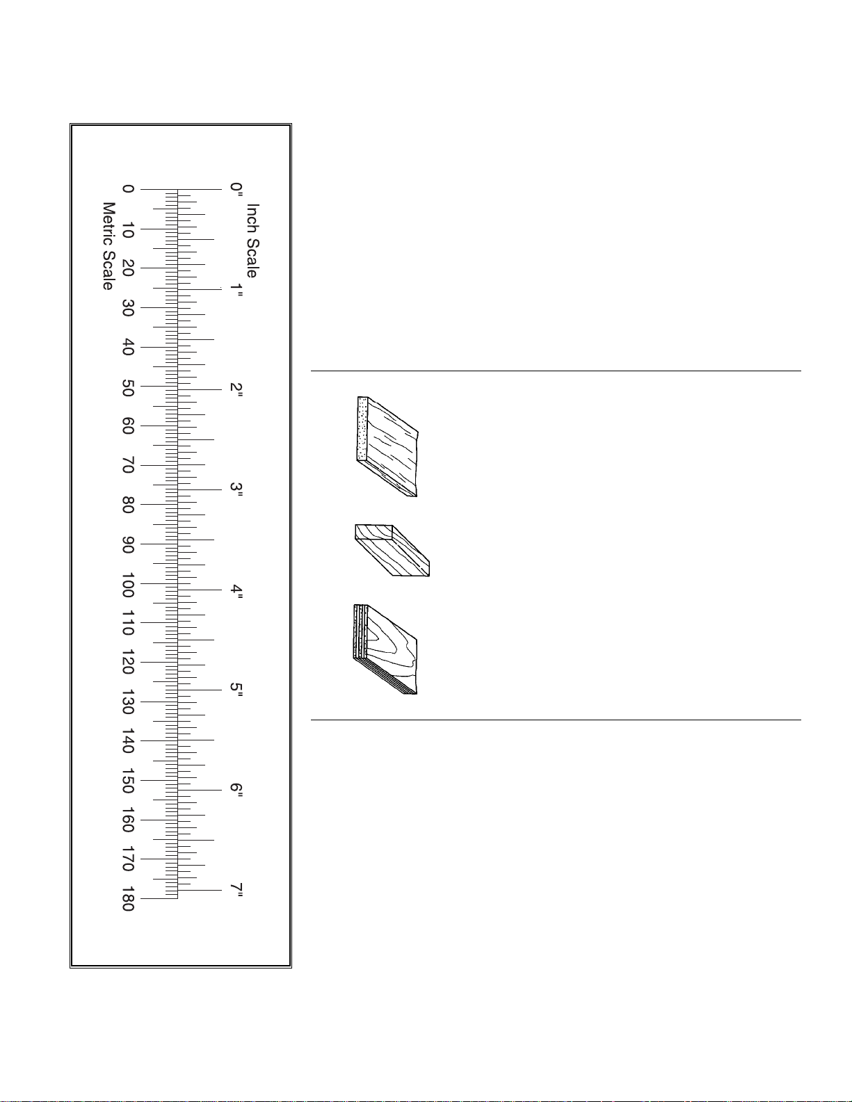
TYPES OF WOOD
BALSA BASSWOOD PLYWOOD
Metric Conversion Chart
Inches x 25.4 = mm (conversion factor)
1/64” = .4 mm
1/32” = .8 mm
1/16” = 1.6 mm
3/32” = 2.4 mm
1/8” = 3.2 mm
5/32” = 4.0 mm
3/16” = 4.8 mm
1/4” = 6.4 mm
3/8” = 9.5 mm
1/2” = 12.7 mm
5/8” = 15.9 mm
3/4” = 19.0 mm
1” = 25.4 mm
2” = 50.8 mm
3” = 76.2 mm
6” = 152.4 mm
12” = 304.8 mm
18” = 457.2 mm
21” = 533.4 mm
24” = 609.6 mm
30” = 762.0 mm
36” = 914.4 mm
6
Page 7
7
1/4" X 2-3/4" X 15" BALSA
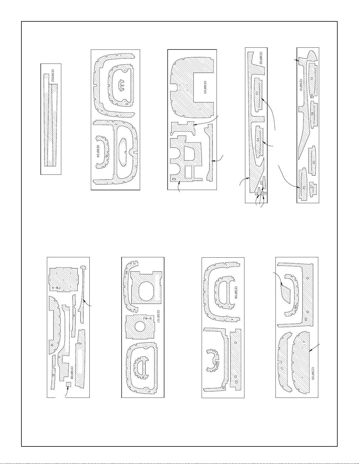
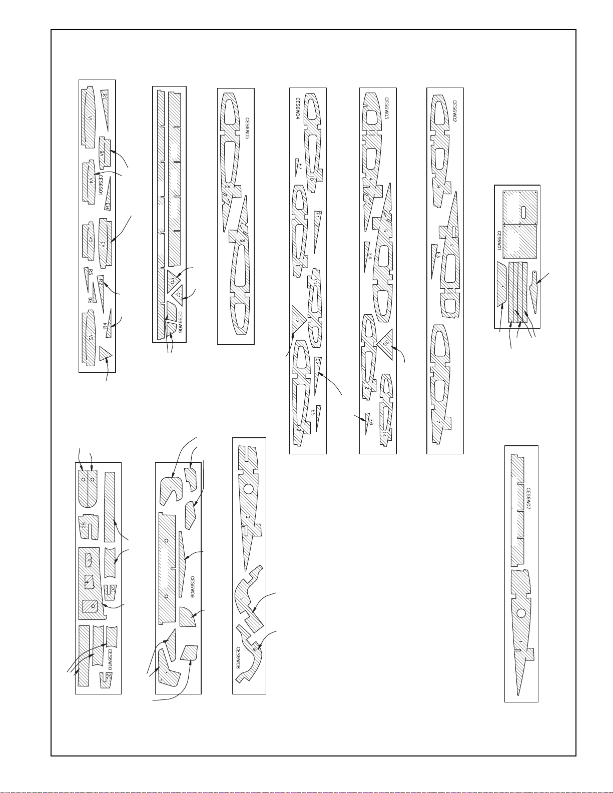
DIE-CUT PATTERNS
FIN TE
STAB TE
CES6S02
STAB TE
1 REQ.
CES6F04
1/8" X 6-5/8" X 19" PLY
NOSE GEAR
DOUBLER
1/8" X 6-5/8" X 19" PLY
CES6F03
3/32" X 3" X 21" BALSA
SIDE SUPPORTS
FIREWALL
WINDOW
FRAME
CES6F02
CABIN SIDE
TOP
3/32" X 3" X 18" BALSA
HORIZONTAL STAB
RIBS “S’s”
CES6F01
1 REQ.
SERVO
TRAY
2 REQ.
2 REQ.
CABIN SIDE
BOTTOM
2 REQ.
DORSAL FIN
FORMERS
CES6F08
1/8" X 5-3/4" X 19" PLY
SADDLE
WING SADDLE BRACE
1/8" X 5-3/4" X 19" PLY
STAB
CES6F07
TANK ROOF
1/8" X 5-3/4" X 19" PLY
CES6F06
GUIDE
1/8" X 5-3/4" X 19" PLY
FIN DRILL
CES6F05
INSTRUMENT PANEL
FUSE KEEL
REINFORCEMENT
HORN
2 REQ.
1 REQ.
1 REQ.
1 REQ.
Page 8
8
3/32" X 3" X 24" BALSA
DIE-CUT PATTERNS
CES6S01
1/8" X 2-3/4" X 21" BALSA
VERTICAL FIN
RIBS “V’s”
RIBS “R’s”
AFT
OUTER
SPAR
RUDDER
CES6W06
AFT
INNER SPAR
GUSSETS
2 REQ.
3/32" X 3" X 21" BALSA
CES6W05
3/32" X 3" X 30" BALSA
CES6W04
3/32" X 3" X 30" BALSA
CES6W03
3/32" X 3" X 30" BALSA
CES6W02
1/16" X 3-3/4" X 11-3/4" PLY
HATCH
HATCH
CES6W01
AILERON
FLAP
FLAP HORN
2 REQ.
1 REQ.
PANT SPACERS
MAIN WHEEL
GUSSET
FIN
PLATES
WING BOLT
GUIDE PARTS
FLAP DRILL
GUSSET
GUSSET
STAB
ELEVATOR
RIBS “E’s”
2 REQ.
2 REQ.
2 REQ.
MAIN WHEEL PANT
AXLE SUPPORT
LOWER SPAR
JOINER
JOINER
CES6W08
CES6W10
1/8" X 3-3/4" X 19" PLY
1/8" X 3-3/4" X 19" PLY
OUTER DIHEDRAL
BRACE PARTS
WING JIG
PARTS
CENTER LE
CES6W09
1/8" X 2-3/4" X 21" BALSA
JOINER (SJ)
STAB
DIHEDRAL
GAUGE
CENTER AFT SPAR
1/8" X 2-3/4" X 21" BALSA
TOP BOTTOM
COWL RING
UPPER SPAR
CES6W07
BRACE PARTS
POLYHEDRAL
2 REQ.
GUIDE PARTS
FLAP DRILL
1 REQ.
2 REQ.
1 REQ.
Page 9
1. Unroll the plan sheets. Re-roll the plans
inside-out to make them lie flat.
2. Remove all parts from the box. As you do, fig-
ure out the name of each part by comparing it
with the plans and the parts list included with this
kit. Using a felt tip or ball point pen, lightly write
the part name or size on each piece to avoid
confusion later. Use the die-cut patterns shown
on pages 7 and 8 to identify the die-cut parts and
mark them before removing them from the
sheet. Save all scraps. If any of the die-cut parts
are difficult to punch out, do not force them!
Instead, cut around the parts with a hobby knife.
After punching out the die-cut parts, use your T-
Bar or sanding block to lightly sand the edges to
remove any die-cutting irregularities.
3. As you identify and mark the parts, separate
them into groups, such as fuse (fuselage), wing,
fin, stab (stabilizer), and hardware.
1. Work on a flat surface over the plans covered
with waxed paper. Refer to the plans to identify
the parts and their locations.
The plans may be
cut apart if space is a problem.
2. Punch out both sets of the die-cut 3/32” balsa
ribs S-1 through S-7. There is a jig tab on the
bottom edge of each of these ribs. If any of
these break off, carefully glue them back on with
a drop of thin CA. Lightly sand any imperfec-
tions. You may need to finish cutting the notch in
the forward portion of S-1 for the Stab Joiner
(SJ) with a knife. Use a pen to mark the exten-
sions of the bottom edge of the ribs across the
fore and aft ends of the jig tabs. These marks
will help when you trim off the jig tabs later.
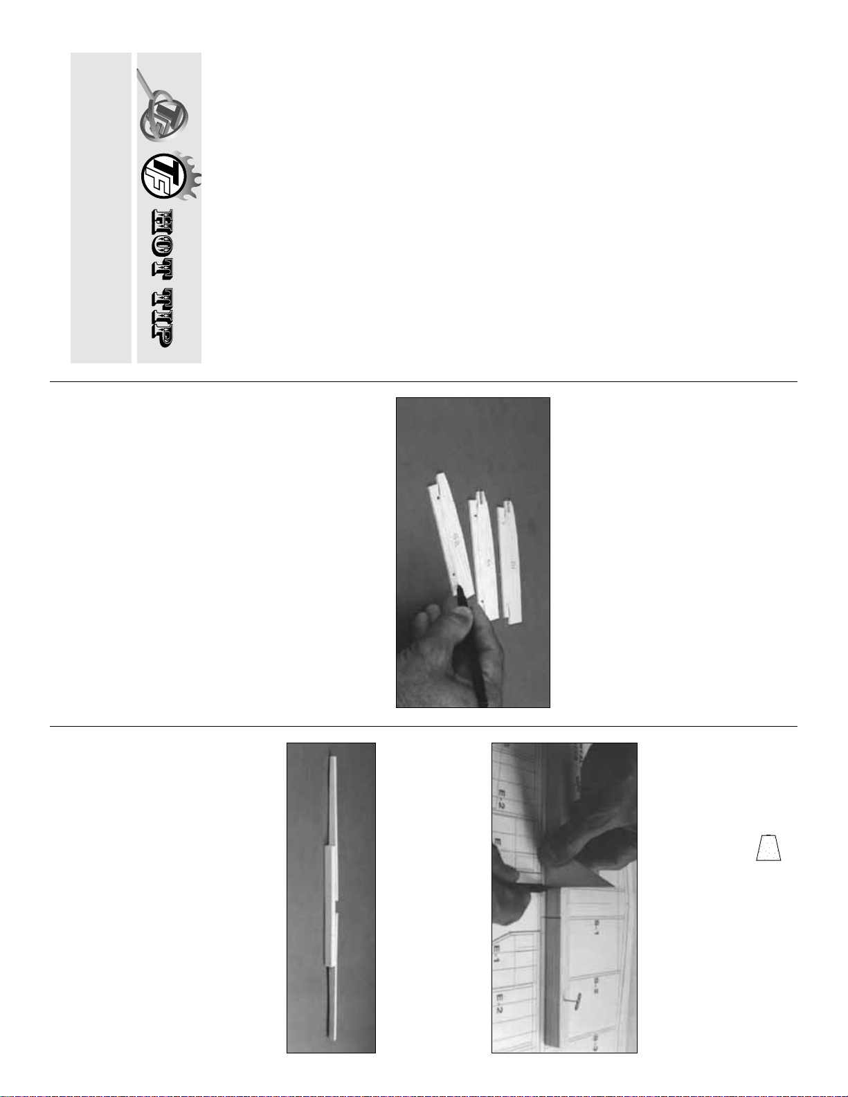
3. The stab Trailing Edges (S) are die-cut from
1/4” balsa. Since some crushing may occur dur-
ing die-cutting wood of this thickness, they are
supplied slightly long and can be trimmed. True
up all edges of these pieces with a T-bar.
❏❏4. Cut the stab Leading Edges (LE’s) to
length from the 1/4” x 15” tapered balsa stock.
They should be about 1/4” longer than the length
shown on the plans for the stab LE.
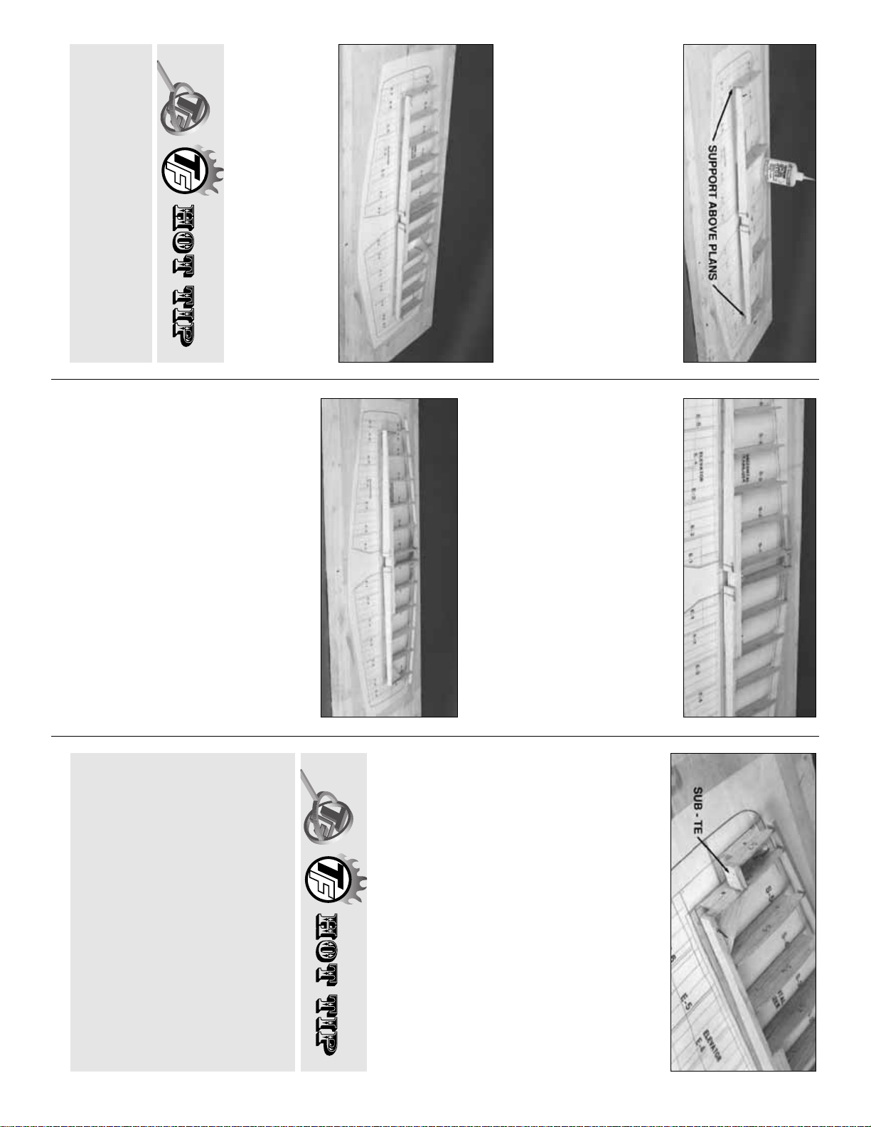
❏❏5. Center the 1/2” x 5/8” x 9-3/4” balsa TE
Center Brace over the plans and pin it in place.
Use a triangle and pen to mark the inboard ends
of the Stab TE. Remove the TE Center Brace
from the building board.
❏❏6. Apply thick CA to one half of the TE
Center Brace, then align the inboard end of a
Stab TE with the reference line you just drew.
Glue the TE Center Brace in position. The TE
Center Brace must be centered on the Stab
TE. Repeat this operation for the other half of
the TE, then use long T-pins to pin the assembly
over the plans.
NOTE: Position the outboard ends of the
TE about 1/2” above the board. The TE
Center Brace should be raised about 3/8”.
(See next photo.)
Build the horizontal stabilizer
BUILD THE TAIL SURFACES
Zipper-top food storage bags are a handy
way to store your small parts as you sor t, iden-
tify, and separate them into sub-assemblies.
Get ready to build
9
FIN / STAB LE
Page 10
❏❏7. Pin the left and right S-3 and S-6 ribs to
the building board over their locations on the
plans. Adjust the height of the Stab TE to align it
evenly with the aft edge of the ribs. Glue the ribs
to the Stab TE and to the TE Center Brace with
thin CA.
❏❏8. Align and glue all of the remaining Stab
ribs to the TE.
❏❏9. Glue the two die-cut 3/32” balsa Stab
Gussets into the junction of S-6 and the Stab
TE. The Gussets should be centered between
the top and bottom of the ribs and Stab TE. Glue
the die-cut 1/8” ply Forward Stab Brace into the
slots in the S-1 ribs and to the inside edges of
the S-2 ribs.
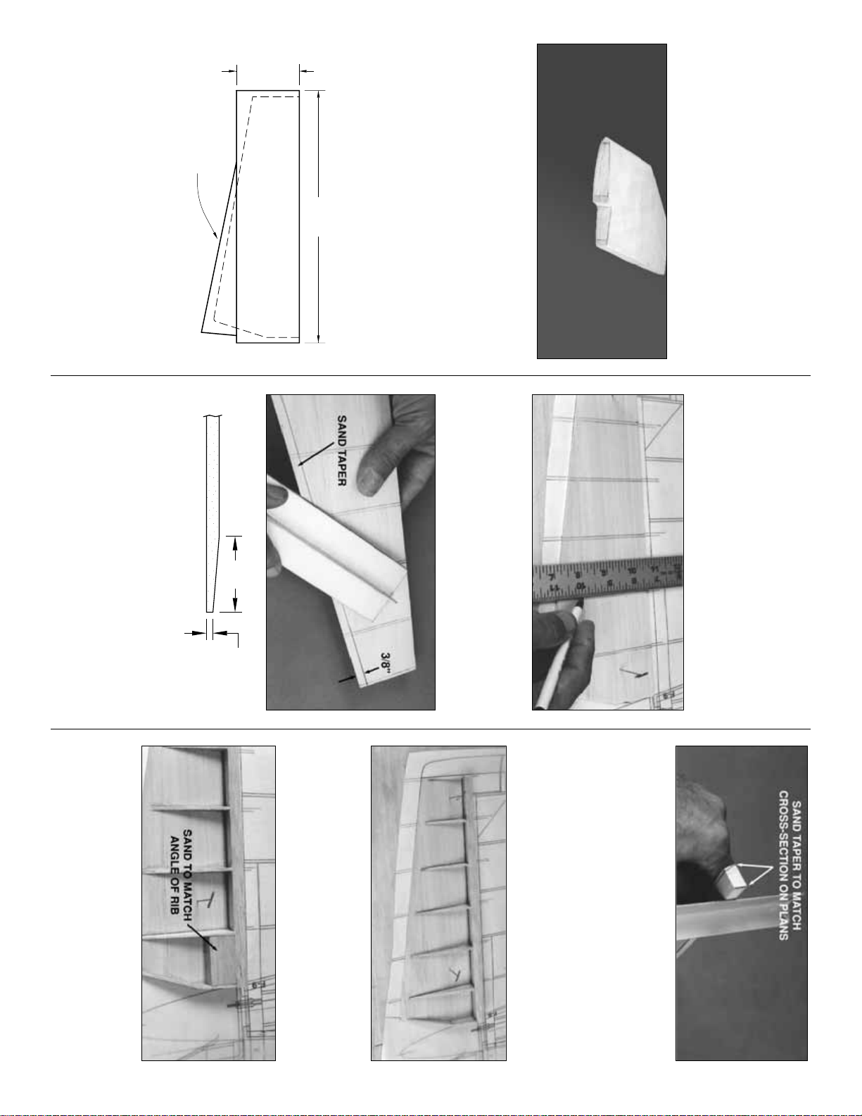
❏❏10. Sand one end of two shaped balsa
Stab LE’s to exactly match the angle at the cen-
ter of the Stab.
Leave the outboard ends long for
the time being.
Center the LE (vertically) on the
front of the ribs, then tack glue the Stab LE’s to
the forward edge of ribs S-1 and S-6 and to the
Forward Stab Brace (this will align the LE). Glue
the remaining ribs to the LE, checking for
straightness as you proceed.
❏❏11. Glue both S-7 ribs to the Stab LE.
❏❏12. Glue the 1/4” x 1/2” x 7/8” balsa Stab
Sub TE to the aft edge of S-7 and to the side of
S-6. Make sure that the Stab Sub TE is posi-
tioned exactly 90 degrees to S-6.
❏❏13. Tr im the Stab LE’s flush with the S-7’s.
Reinforce all of the joints with medium CA.
Sand the tips of the LE, sub TE, and TE flush
with S-7 and S-6.
❏❏14. Remove the pins, then lightly sand the
top surface of the stab frame to blend all parts
and remove any excess CA. Take care not to
change the shape of the airfoil.
HOW TO MAKE WING AND STAB SKINS
A. Wherever practical, pre-join the balsa
sheets to make a “skin” before attaching them
to the structure.
B. Many modelers like to sort the wood so they
can put the best wood with the most even
grain structure on the top of the wing and stab.
C. Make your skin larger than needed to allow
Lightly sand a bevel along the front edge of
the Stab ribs to match the sweep angle of the
LE. This will give you a better fit and a stronger
glue joint.
10
Page 11
❏❏15. Make two 6”x 30” stab skin planks
from four 1/16” x 3” x 30” balsa sheets. From
these planks, cut four stab skins. See the sketch
for the proper layout on the wood. Refer to the
plans for the exact shapes and sizes, but
remember to make the skins slightly oversize.
❏❏16. Pin the stab structure to your building
surface using pins only at the tips and diagonally
under the LE & TE. Make sure that the jig tabs
are flat on the building surface. Don’t hide the
pins under the skin.
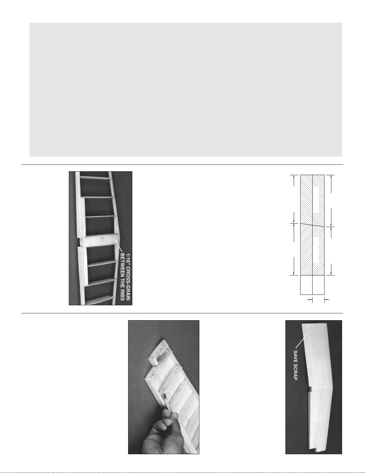
❏❏17. Use the off-cut 1/16” material from the
skin planks to make a 1” wide cross-grain strip to
fit between the S-1’s from the LE to the TE. Glue
the strip in place between the ribs, flush with the
top edge.
❏❏18. Test-fit the skins over the stab frame.
Make sure the skins meet flush at the center.
Adjust them with a sanding block if necessary.
Apply an even bead of medium or thick CA to
the upward-facing edges on one side of the
frame. Place a skin in its proper position and
press it firmly down until the glue has set.
Repeat this step for the other top skin. Trim off
the excess balsa, but save any big scraps for
use when making the elevators.
❏❏19. Remove the stab from the building board.
Tr im off the jig tabs with a sharp knife. Trim and
blend the LE and TE to the ribs as you did before.
Check all glue joints, adding glue as necessary.
❏❏20. Cut another 1” wide cross-grain strip
from 1/16” x 6” off-cut balsa sheeting and glue it
between the two S-1 ribs flush with their bottom
edges.
❏❏21. It’s important to get a good glue bond
between the stab frame and the bottom stab
skins. Apply a heavy bead of medium or thick
for misalignment. On a large surface such as
the wing, 3/8” extra is suggested.
D. To make skins, the following steps
are suggested:
1. Tr ue up the edges of the sheets with a
metal straightedge and a sharp knife or a
“T-Bar” sanding block.
2. Test-fit the sheets together to make sure
they match well.
3. METHOD “A”: Edge glue the sheets
together with thin CA, over a flat surface cov-
ered with waxed paper. A quick wipe of the
joint with a fresh paper towel will remove
excess glue and make sanding easier. Mark
the poorest surface to identify it as the “inside”
surface.
METHOD “B”: Edge glue the sheets
together with Titebond
®
wood glue. (Titebond
is easier to sand and won’t leave a ridge at the
seam, as CA is prone to do.) Smear the glue
lightly along an edge with your finger, then join
the sheets over a flat (waxed paper covered)
building board. Pin the sheets to the board to
hold them together. Wipe off any excess glue
before it dries.
4. Place the skin on a large flat surface
and sand it with a large flat sanding block and
fresh, sharp 220 paper. Use light pressure and
a brisk circular motion.
5. Tr im the perimeter of the sheet to even
things out.
11
STAB SKIN
STAB SKIN
13"12-1/8"
12-1/8"13"
3"
Page 12
CA to all of the
upward facing
edges on one side
of the stab frame. Place a skin on the frame and
hold it in place with your hands until the glue
sets. Repeat this for the other bottom skin. Be
careful not to bend or twist the stab during
this step.
❏❏22. Tr im off the excess balsa from around
the perimeter of the stab. True up the ends of
the stab with a sanding block. Round the LE of
the stab to match the cross section on the plan.
❏❏1. Cut two 1/16” x 3” x 36” balsa sheets to
make four 15” long sheets. Refer to the sketch and
the elevator plans, then glue the leftover balsa
“wedges” that you cut from the stab skins to the 15”
sheets. These joined sheets will be used to make
the top and bottom Elevator skins.
❏❏2. Use the pattern on the plans to cut four
Elevator skins. Sort the skins so that the best
surfaces will be facing outward, and on the top.
❏❏3. Cover the elevator plan with waxed
paper, then pin a skin in position. Use the “tic”
marks on the plan to draw the rib locations on
the skin.
❏❏4. Draw a line along the length of the skin’s
TE 3/8” in from the edge. Remove the skin from
the building board, then holding it along the
edge of your work bench, sand a taper from the
line towards the TE so that the TE will be
approximately 1/32” thick.
❏❏5. Locate the 3/8” x 3/4” x 11-5/8” shaped
balsa Elevator LE. Draw two lines, 1/32” in from
each edge, on one side of the LE as shown in
the photo. Use the lines as a reference to taper
the top and bottom of the LE toward the elevator
TE with a T-bar sander. Proceed carefully,
checking your progress against the height of
the elevator ribs at each location.
❏❏6. Glue the LE to the inside surface of the the
elevator skin, flush with the forward edge of the
skin. Glue the 3/32” die-cut balsa ribs (E-1 through
E-7) to the skin and to the LE with thin CA.
❏❏7. Test fit a 1/2” x 1” x 1-5/8” balsa Torque
Rod block between ribs E-1 and E-2. Sand the
ends, if necessary, for a good fit. Sand a slight
angle on the forward edge of the Torque Rod
Build the elevators
12
3"
SCRAP
ELEVATOR SKIN
15"
3/8"
1/32"
Page 13
block (the one that will contact the elevator’s LE)
to match the angle of the LE. Glue the Torque
Rod block in position when you are satisfied with
the fit.
❏❏8. Carefully sand the top of the Torque Rod
block flush with the taper of the ribs.
❏❏9. Mark and sand the
inside
TE of an ele-
vator skin as you did in step 4. Apply a bead of
thick CA to LE, TE, and all ribs, then glue the top
skin into position. Hold the assembly flat until the
CA cures.
❏❏10. True up all edges with a T-bar or
sanding block.
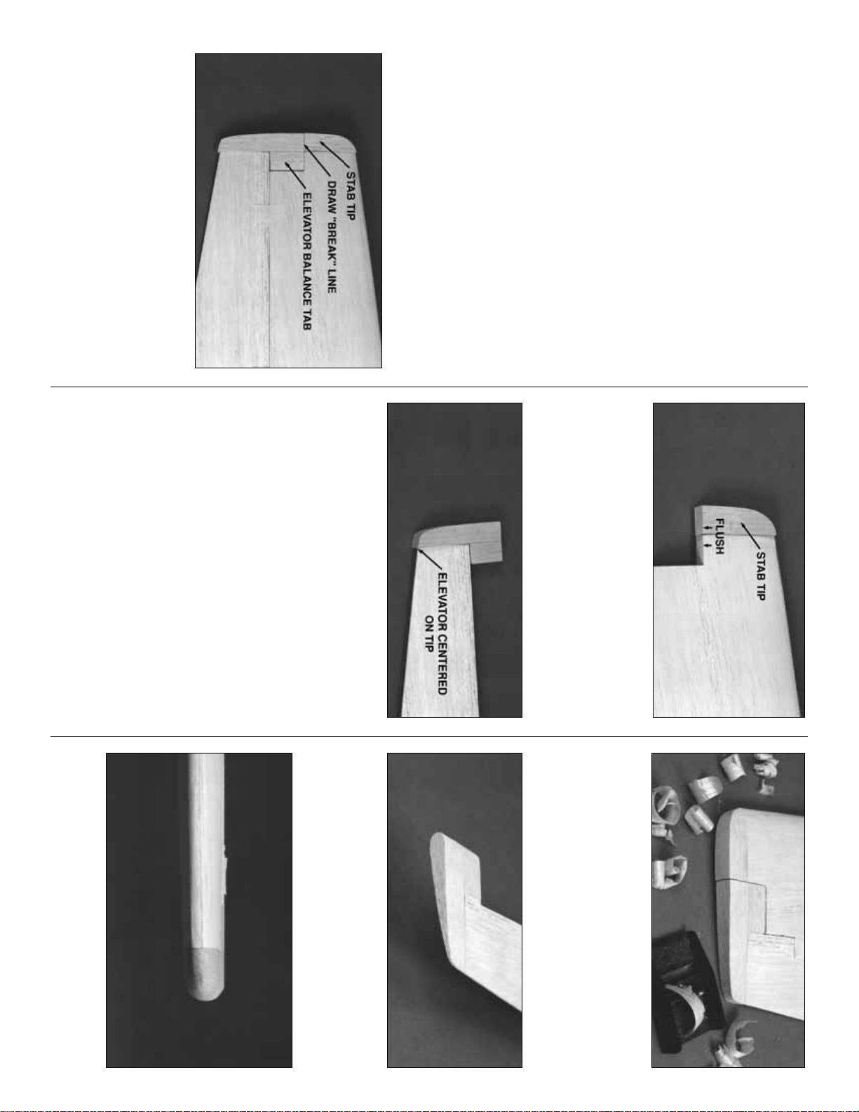
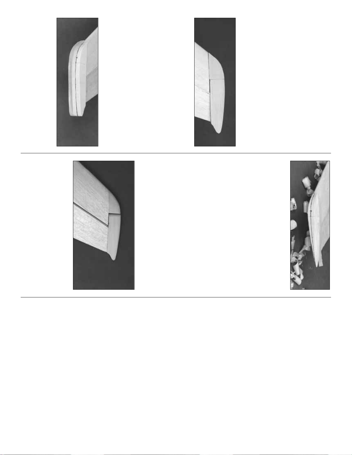
❏❏11. Test fit the Stab, Elevator, 5/8” x 7/8” x
6-1/2” shaped balsa Stab Tip, and the 5/8” x
27/32” x 1-9/16” balsa Elevator Balance Tab
together. Make any adjustments with light sand-
ing. Mark the
“break”
between the Stab and the
Elevator on the Stab Tip. Cut the Stab Tip apart
along this line.
❏❏12. Glue the forward balsa Stab Tips
in position.
❏❏13. Glue the Elevator Balance Tab flush
with the Elevator Tip. Center the Stab Tip on the
outboard end of the Elevator, before using thick
CA to glue in place. Make sure that both the
Elevator LE and TE are centered before the
CA cures.
❏❏14. Tape the elevator assembly to the Stab.
Make sure that the Stab Tip and Elevator
Balance Tab are flush along the outside edge.
There should be a 1/32”-1/16” gap between the
Elevator Balance Tab and the Stab. If not, use
your T-bar sander to correct the problem by
alternately sanding the inside edges of the
Elevator Balance Tab and the Stab.
❏❏15. When satisfied with the fit, use a razor
plane and sanding block to shape the Stab Tip
to blend with the Elevator and Stab.
❏❏16. Sand a radius around the Balance Tab
as shown in the photo.
❏❏17. Sand a radius around the outboard
edges of the Stab and Elevator Tip.
13
Page 14
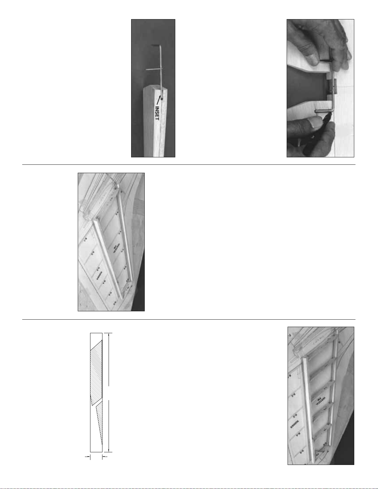
❏ 18. Tape the Elevators to the Stab making
sure that you have the correct clearance around
the Balance Tabs. Hold the bent 1/8” Elevator
Joiner Wire and Horn up to the Elevator and
mark the location of the Joiner Wire holes that
will be perpendicular to the hinge line (see the
plans for the joiner location).
NOTE: The Elevator Horn is off-center.
When looking at the top surface of the
Stab, the Horn will be to the right of
Stab center.
❏ 19. Drill 9/64” holes in the elevators for the
Joiner wire. Cut slots inboard of the holes to
allow the wire to be inset into the elevators, flush
with the LE. Sand the Elevator LE to a “V”
shape to allow for Elevator travel — refer to the
plans for the correct angle.
❏ 20. Test-fit, but do not glue the joiner wire into
the Elevators. Check to see that the Elevators
align with each other properly and that they fit
the Stab without binding. Make adjustments by
removing the Joiner Wire and then bending it,
if required.
❏ 1. Cover the Fin/Rudder section of the plans
with waxed paper.
❏ 2. Punch out the die-cut 3/32” balsa ribs V-1
through V-6. Be sure to preserve their jig tabs.
NOTE:
If you plan to install an operational
beacon light on top of the Fin drill a 3/16”
hole through the center (front to back, top
to bottom) of each rib. This hole will pro-
vide a passage for the wiring.
❏ 3. Cut a 15” length of the tapered 1/4” balsa
Stabilizer/Fin LE stock to match the plans
exactly, as the length of the LE sets the angle of
the fin.
Notice that the Fin LE fits into a notch on
top of F-8.
❏ 4. Punch out the die-cut 1/4” balsa Fin TE
and lightly sand the edges to touch them up.
Sand (or cut) the tips to match the sweep angle
as shown on the plans.
❏ 5. Sand an angle on the ends of each rib to
match the sweep angle of the LE and TE. Pin
ribs V-1 and V-6 to the building board over their
proper locations. Center the LE on the front of
the ribs and glue it in place. Center the Fin TE
on the aft edge of the ribs and glue it in place.
❏ 6. Put r ibs V-2 through V-5 into their places
and glue them to the LE and TE. Remember, all
jig tabs should contact the work surface.
❏ 7. Glue the die-cut 3/32” balsa Fin Gusset
into the corner of V-6 and the Trailing Edge.
❏ 8. Apply extra CA+ glue to any joints that do
not appear to be well glued.
❏ 9. Blend the LE to match the ribs on the
upward facing (left) fin side. Sand the TE, if nec-
essary, to blend smoothly with the ribs.
❏ 10. Make a skin for each side of the fin using
1/16” x 3” x 30” balsa sheet. Leave excess balsa
on one edge of the skin so it overhangs past
V-1 about 5/8”; this will allow fitting to the stab
later. With the structure flat on the table, glue on
the left (upward-facing) skin.
Build the fin
14
FIN SKIN
3"
30"
Page 15
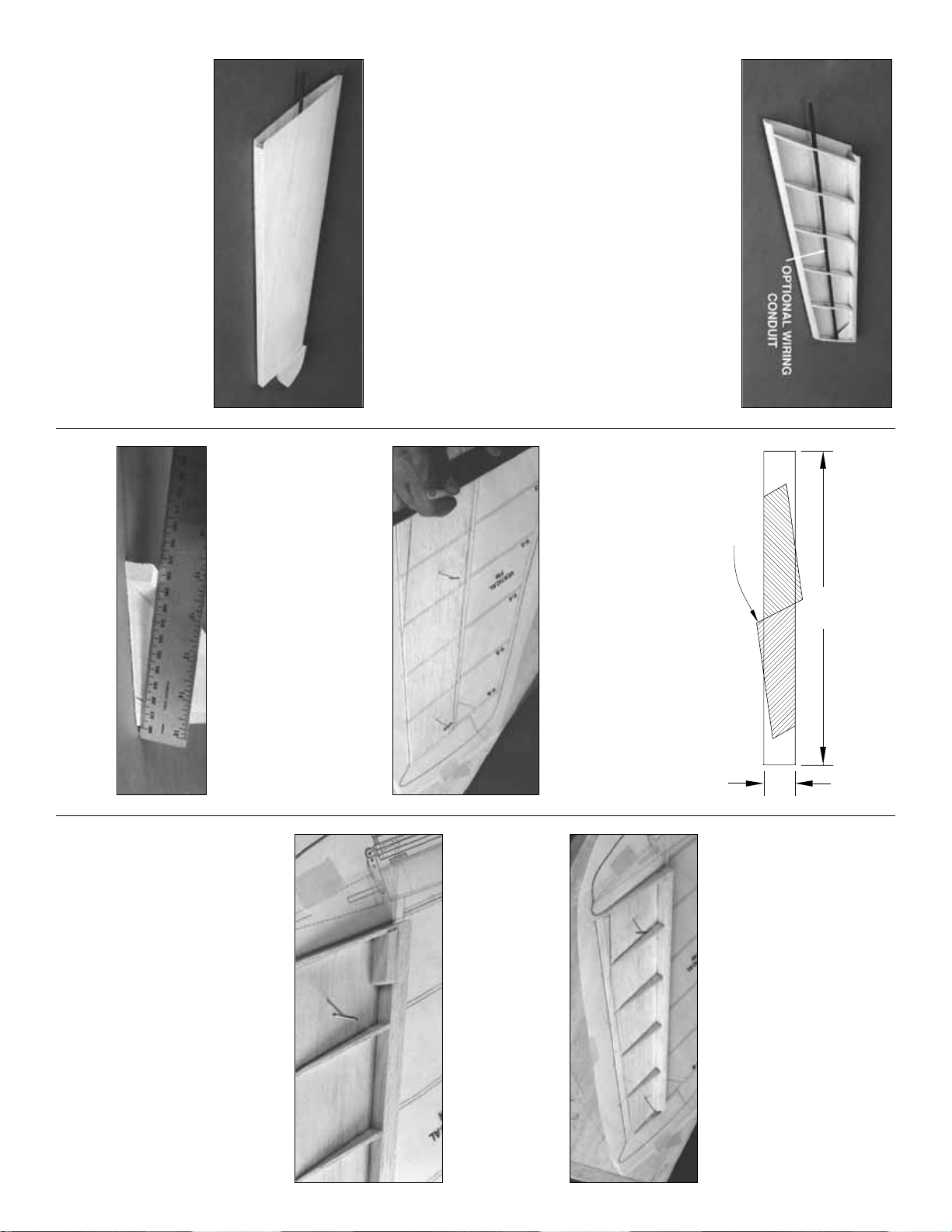
❏ 11. Remove the fin from the building board
and trim off the jig tabs. Blend the LE and TE to
the ribs on the right side of the fin.
NOTE:
If you plan to route wiring for a bea-
con through the fin, install a 15” length of
outer pushrod tube (not supplied) through
the 3/16” holes you drilled in step #2. Glue it
in position with medium CA, leaving the
excess tube protruding from V-1.
❏ 12. Use medium or thick CA to glue on the
right side skin. Be sure to get a good bond
between the ribs and the skin.
❏ 13. True up the edges of the fin sheeting with
a sanding block. Shape the LE to match the
cross section on the plans. Don’t trim the bottom
edge of the sheeting at this time.
❏ 14. Glue the shaped 3/4” balsa Fin Tip to the
top of the fin. Shaping should be done later, with
the fin taped to the rudder.
NOTE:
If adding a beacon light, drill a hole
through the top of the Fin Tip that aligns with
the wiring tube before you glue it in place.
❏ 1. Use one 1/16” x 3” x 30 balsa sheet to
make two rudder skins, using the rudder skin
pattern on the wing plan. You will need to edge
glue a small wedge shaped piece of sheeting to
the TE of the skin to provide the correct width.
You should have more than enough material left
over from the previous assemblies to accomplish
this step.
❏ 2. Pin one of the rudder skins to the (wax
paper covered) plans and draw the location of
each rib using the “tic” marks as a guide. Draw a
line the length of the rudder skin, 3/8” in from the
aft edge, as you did with the elevators. Remove
the rudder skin from the board and taper the aft
edge to 1/32”. Taper the aft edge of the other
rudder skin to 1/32”. (See next photo.)
❏ 3. Locate the 3/8” x 3/4” x 12” tapered balsa
rudder LE. Cut the tips to match the sweep
angle of the rudder. Lightly sand both sides of
the rudder LE to match the angle toward the aft
edge of the rudder.
❏ 4. Re-pin the rudder skin over the plans. Glue
the rudder LE to the surface of the rudder skin,
flush with the front edge, using medium CA. The
wide end of the rudder LE is at the bottom end
of the rudder.
❏ 5. Slightly taper the forward edge of the rudder
ribs R-1 through R-6 to match the sweep angle of
the rudder LE, then glue them in position over
the location lines that you drew in step #2.
❏ 6. Shape one end of the 1/4” x 1/2” x 1-1/4”
balsa rudder Torque Block to match the angle
at the intersection of the rudder LE and R-1.
Glue the Torque Block in position when satisfied
with the fit.
❏ 7. Remo v e the rudder assembly from the board,
then lightly sand the frame to blend all joints. Glue
the second rudder skin to the frame with thick CA.
To prevent twists, be sure that the assembly is held
on a flat surface while the CA cures.
Build the rudder
15
EXCESS
30"
3"
Page 16
❏8. True up all rudder edges with a sanding b lock.
❏ 9. Position the rudder against the TE of the fin
with the top of the rudder 1/32” above the top
of the main body of the fin. Tape the fin and
rudder securely together with masking tape.
NOTE: Before proceeding, study the photo
at step 15 to see what you will accomplish
in the next six steps.
❏ 10. Test fit the 3/4” shaped balsa Rudder Tip
on top of the rudder. It should butt against the
Fin Tip squarely, and have a clearance gap of
1/32” above the fin. Make adjustments with a
sanding block if needed.
❏ 11. Use thick CA to glue the Rudder Tip to the
rudder. Be sure that everything is centered
before the CA cures.
❏ 12. Draw a center reference line across the
top of the rudder and fin blocks. A piece of
masking tape stretched across the center of the
blocks will help you draw a fairly straight line.
❏ 13. Use a razor plane and sanding block to
shape the top of the fin and rudder. For scale
realism, the Rudder Tip should be slightly
wider than the rudder. Apply 4 layers of masking
tape to each side of the rudder to prevent you
from removing too much material. The Fin Tip
may be sanded flush with the fin. Round off the
top 3/8” of both the Fin and Rudder Tips. When
the top is shaped and sanded, remove all mask-
ing tape.
❏ 14. Draw a centerline on the rudder’s LE.
Sand a “V” bevel along this line with reference to
the plans for the correct angle. Hinging and
installation of the torque rod will come later in
the assembly process.
❏ 15. Sand a radius around the forward edge of
the Rudder Tip. Hold the fin and rudder together
to check the clearance between the Rudder Tip
and the Fin Tip. Continue sanding the Rudder
Tip radius until there is a 1/32” gap between the
two parts.
Okay, the tail feathers are more or less com-
plete, so by now you are on a roll. The stab
looks like the wing for a .20-size model, doesn’t
it? We’ll build the wing next so you’ll really have
something to impress your buddies when they
drop in to see “how the ol’ Cessna is doing.”
NOTE: The wing panels are built “UPSIDE-
DOWN” on the plans. The jig tabs are
attached to what is, in the end, the TOP sur-
face of the wing. Since it is the standard con-
vention to show the Top View of the wing,
and the wing panels are built upside-down,
the LEFT wing panel is built over the RIGHT
Wing Top View and vice-versa. This does not
present any problems — just be sure to build
a left and a right wing.
❏ 1. Punch out all the die-cut 3/32” and 1/8”
balsa wing Ribs. Smooth out any imperfections
with sandpaper. Be sure to keep the jig tabs
attached to the ribs.
❏ 2. Punch out the 1/8” ply Doublers and Wing
Bolt Plates.
Build the center section
BUILD THE WING
16
Page 17
❏ 3. Lay out both sets of balsa Ribs W-2 and W-
3, ply Doublers W-2B and W-2C, and the ply
Wing Bolt Plates exactly as shown in the photo.
This way you won’t assemble two right or two left
sides.
Glue the Doublers to the Ribs and laminate
the two pairs of Wing Bolt Plates with
30-Minute Epoxy. After the epoxy has cured, test
fit the Wing Bolt Plates into the slots at the aft end
of W-2 and W-3. Make slight adjustments to the
slots if required, but don’t make the fit too loose
as this is a critical area for a nice tight bond.
❏ 4. Attach the wing plan (the part showing the
center section) to a flat building board and cover
it with waxed paper.
Cutting apart the wing panel
sections of the plan makes handling easier.
❏ 5. Locate the 3/8” x 3/8” x 20” basswood
Center Spar. Cut two 9-1/4” pieces from it. Pin
one of the 3/8” x 3/8” x 9-1/4” basswood Center
Spars to the plan using the method shown in the
sketch. The Center Spar is a little longer than
actually needed to allow for the dihedral angle at
W-3. It will be trimmed to size later.
❏ 6. Position rib W-1 and rib assemblies W-2
and W-3 on the Center Spar with the jig tabs
touching the plan. Be sure that the ply doublers
are facing the correct direction.
❏ 7. Insert (without gluing) the die-cut 1/8” balsa
Center Aft Spar into the slots above the jig tabs.
Insert the second basswood Center Spar into
the forward rib notches. Make sure that both
Spars are flush with the upper edge of the ribs.
❏ 8. Interlock the 1/8” die-cut ply Center LE with
the tabs on the LE of ribs W-3 and W-1.
❏ 9. Study the structure. Are all parts over their
respective locations on the plans and in align-
ment? If not, lightly use fine grit sandpaper to
adjust the fit.
Don’t reach for the CA yet!
❏ 10. Make sure the W-3 ribs are flush with the
Aft Spar and the Center LE. Use the 1/8” die-cut
ply Dihedral Gauge on the inside of the W-3
ribs at the forward Spars to set the ribs angle at
this location. Hold a straightedge alongside the
W-3’s to check for straightness.
❏ 11. When you are sure that everything is
straight and true (sight down the TE and shim
any low ribs with folded paper under the jig tabs)
wick thin CA into every joint. Hold the LE and
W-3’s in tight contact for a few seconds to allow
the CA to work. Follow the initial gluing by apply-
ing a fillet of medium CA around the joints.
Isn’t interlocking construction great?!
NOTE: Do not use any CA until step 11.
17
Page 18

❏ 12. Check the fit of the 1/4” x 1-7/8” Dowels
and the Wing Bolt Plates. Mix up a small batch of
6-Minute Epoxy, then glue these parts in position.
NOTE: The Wing Bolt Plates must be flush
with the outside surface of the W-3’s.
❏ 13. Trim and sand only the basswood Center
Spar ends flush with the W-3’s. Be sure to leave
the
tips
of the Center Aft Spar and the Center
LE in place as they will be used when joining
the center section to the outer wing panels.
❏ 14. Cut a 9-1/4” length from a 3/32” x 1/2” x
30” tapered balsa TE stick. Look at the cross
section on the fuse plan for the angle of the TE.
Center the TE on the aft edge of the center sec-
tion ribs, then glue it in place with thin CA.
Carefully sand the ends flush with the W-3’s.
❏ 15. Trim four of the pre-cut 1/16” x 2-3/4” x 1-
1/2” Shear Webs to fit between the W-1 and W-
2 ribs at the forward Center Spars. Glue the
Shear Webs to both sides of the Center Spars
with medium CA
This completes the wing center section frame,
so, zipping right along, let’s move on to the outer
wing panels.
HINT: You will speed up the building process if
you prepare two “wing panel kits” before you
start gluing. We also suggest that you assemble
all four spars even though you may only be
building one half of the wing at a time.
❏ 1. Place a wing panel plan on your building
board and cover it with waxed paper.
❏❏2. Cut four 1/8” x 3/8” x 24” hard balsa
Outer Spar Doublers to 22-3/4”. Sand a chisel
point on one end of each piece starting 2” from
the end.
❏❏3. Use medium CA to glue the Outer Spar
Doublers to the 1/4” x 3/8” x 36” balsa Outer
Spars. The un-tapered end of the Outer Spar
Doubler must be flush with one end of the
Outer Spar.
❏❏4. Pin an Outer Spar assembly to the
building board at three or four locations using
the cross-pinning technique.
NOTE: Do not
apply glue to Ribs until Step 7.
❏❏5. Position the die-cut 3/32” balsa ribs W-4
through W-14 on the spar. These should be ver-
tical and aligned over their appropriate locations
as indicated on the plans.
The jig tabs located
near the aft end of the ribs should all contact
the work surface.
Build outer wing panels
18
SPAR DOUBLER
OUTER SPAR
2"
WING TE
Page 19

❏❏6. NOTE: Complete this step only if
you’re adding operational flaps. Slide two lay-
ers of waxed paper between ribs W-6 and W-7
from the TE to just forward of the Aft Inner Spar
notch. The waxed paper will help prevent the
ribs from sticking together when you cut the
Flaps free later on.
❏❏7. Fit the die-cut 1/8” balsa Aft Inner Spar
and Aft Outer Spar into the aft notches of r ibs
W-4 through W-6 and W-7 through W-14 respec-
tively. The upward facing edge of the Aft Inner
Spar protrudes above the ribs. Make a mental
note of the protruding angle, then, after remov-
ing the Aft Inner Spar from the frame, sand a
bevel on this edge so that it will be flush with the
ribs.
Although you could sand it in place, you
would run the risk of deforming the wing ribs.
❏❏8. Sight down the TE of the wing from the
root end making sure all ribs are aligned. Use
paper to shim under the jig tabs of any ribs that
are low.
❏❏9. Check that the upward-facing edges of
the ribs and the top surface of the Aft Spars are
even and that all of the jig tabs are touching the
work surface or shims. When everything is
aligned, wick thin CA into all joints. Wick thin CA
into all seams around the mating surfaces of
W-6 and W-7.
❏❏10. Place part A and B of the 1/8” die-cut
ply Outer Dihedral Braces over the pattern on
the plan and mark the indicated reference line
on both long edges of each piece.
NOTE: Both parts are slightly narrower at
one end. Use 6-Minute Epoxy to glue the
parts together as shown in the photo. Be
sure to make one left and one right set.
❏❏11. Use a razor saw to cut a 1/4” wide slot
from the upper forward Spar notch down to the
lower Spar through ribs W-6 and W-7. Insert the
Outer Dihedral Brace into the slot you just cut
with the narrow end toward the wing tip and the
short por tion of the assembly facing the leading
edge. The angled edge should be facing upward
between ribs W-7 and W-8. Don’t glue it in
place yet, but leave it in position.
❏❏12. Hold the upper Outer Spar in position
on the ribs, with the inboard end flush with W-4.
Mark the Spar at the seam between ribs W-6
and W-7. Score the inside of the spar two thirds
of the way through with a razor saw.
The
inside
is the side with the tapered 1/8” Outer
Spar Doubler.
❏❏13. Press the upper Outer Spar into the
wing notches and check for a flush fit at each rib.
When satisfied, remove the Outer Spar, then use
30-Minute Epoxy to glue the Outer Dihedral
Brace in position. Apply a bead of epoxy to the
upper edge of the Outer Dihedral Brace, and,
before the epoxy cures, install the Outer Spar
Assembly and glue it to all the ribs with thin CA.
NOTE: Work some epoxy into the the saw-
cut before laying the Spar in place.
❏❏14. Cut four 3-1/8” long Servo Hatch Rails
from 1/4” x 3/8” x 30” balsa. Glue two of these
pieces into the notches in ribs W-4 and W-5 and
two between ribs W-7 and W-8. These will sup-
port the flap and aileron servo hatches. Install
19
Page 20

the rails even if you don’t plan to add flaps, as
they add a little extra strength and fill in
the notches.
❏❏15. Glue the 1/8” die-cut Gusset G-3 to the
Aft Outer Spar and W-7, as shown on the plans.
❏❏16. Hold the 36” shaped balsa LE up to the
wing and mark it at W-7. Cut three quarters of
the way through the LE (from the flat side) with a
razor saw to allow it to flex at W-7. Center the
LE vertically on the ribs, then tack glue it in
position at W-4, W-7 and W-14. Sight down the
LE from both ends to check that all of the ribs
are centered and that the frame isn’t curved or
twisted. Once again, be sure that all the jig tabs
are firmly on the building board, then perma-
nently glue the LE to all of the ribs.
❏❏17. Cut the tapered 30” balsa Flap Spar to
fit from W-4 to W-7 then glue it into the “V”
notches just behind the aft Inner Spar.
❏❏18. Center a 1/2” x 15” tapered balsa TE on
the aft edge of W-4 and the last W-6, then glue it
in position to only W-4 and W-6. Lay a straight-
edge across the aft end of the ribs to check that
all ribs are aligned and level and that the TE is
straight. When everything looks good, glue all
the remaining ribs to the TE, centering each rib
as you proceed.
❏❏19. Glue the die-cut 1/8” balsa gussets G1
and G2 in position, as shown on the plans.
❏❏20. Trim the excess material from the
Spars, LE, TE, etc., and sand all ends flush.
Reinforce all joints that still need extra glue by
adding medium CA.
❏❏21. Refer to the plan for the location of the
single and double 1/16” x 2-3/4” x 1-1/2” balsa
Shear Webs. Glue the Shear Webs in position
with thick CA (Not between W-4 and W-5).
❏❏22. Locate the 1/2” x 1/2” x 6” balsa stick.
Cut six 1” lengths to use as Aileron Hinge
Blocks. Fit and glue 3 blocks where shown on
the plans. Save the other 3 for use on the sec-
ond wing panel.
Well, that about wraps up the framing for half of
the wing. Take a short break to admire your
handiwork, have a cup of coffee, clean the CA off
your fingers, and kiss your spouse good night.
When you’re fully revived, clean the sawdust off
your bench, swap the plan sheets, and get busy
building the other half. You can rest later.
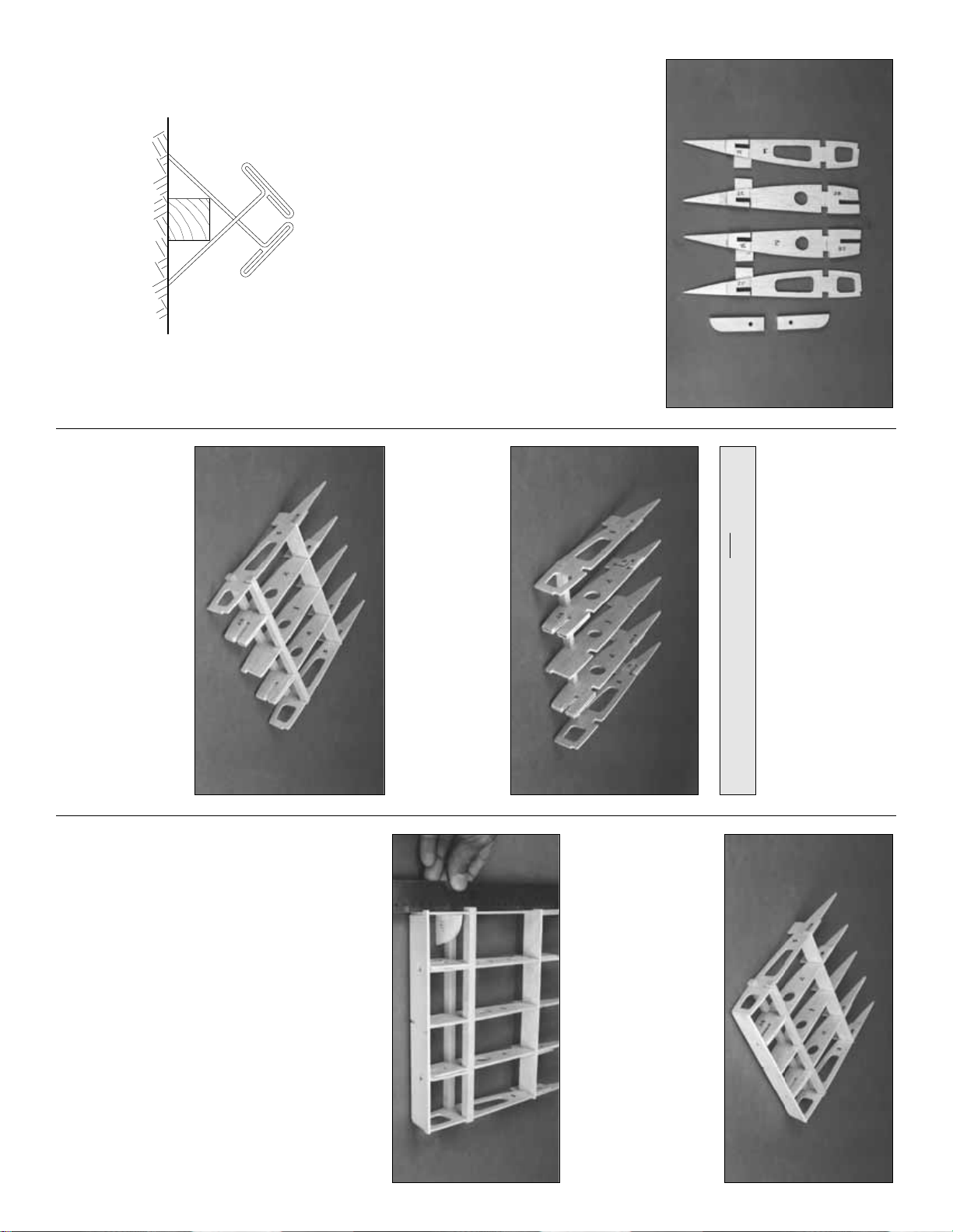
❏❏1. Position the three 1/8” ply parts of the
Polyhedral Braces over the sketch on the
plans. Look carefully at each piece and you will
notice that they form a slight “V” shape, with one
end longer than the other. After you align each
piece over the drawing, mark an index line on
each part as shown, then extend it around to
both edges.
❏❏2. Without gluing, stack the three pieces
together and compare the assembly with the
photo and the plans. Repeat this process with
the second set of braces,
but this time flip the
pieces end-for-end
when you stack them.
Prepare the polyhedral braces
20
FLAP SPAR
Page 21

You should now have a right hand and a left
hand set of Polyhedral Braces, as shown in the
photo.
Tracing around the edges of the two
shorter par ts will help alignment when you glue
them together.
❏❏3. When satisfied that the braces are
accurate, use 6-Minute Epoxy to glue the parts
together with the alignment marks perfectly
aligned.
❏❏1. Carefully remove a 3/8”-wide strip of balsa
from between the spars on both the W-3 ribs of
the Center Section and the W-4 ribs of the outer
panels. This will allow the Polyhedral Braces to be
inserted and glued between the spars.
❏❏2. Test fit (but don’t glue) the Polyhedral
braces into the center and outboard wing panels.
The longer end of the joiner is the end that
plugs into the outboard panels. Sand the
ends, if necessary, for a good fit. The wing
panels should mate evenly along the joint
without any unnecessary twisting or bending to
line things up. If you have to force the panels to
fit, locate the problem and fix it before
proceeding. Any twists will become a permanent
part of the structure after the panels are joined
and will be difficult to correct.
❏❏3. Use only a spot of CA to glue the two
1/4” x 1-1/16 “ x 5-7/8” balsa Wing Jig Blocks
to the W-2 jig tabs and the top of the spar.
Now for the hard part — cleaning a space on
your work bench large enough to spread out and
join the wing.
IMPORTANT: Check your work surface with
a metal straightedge to make sure that it’s
perfectly flat before proceeding. Make a
“dry run” of the following step before
actually performing it with glue.
❏❏4. Place the Center panel on the Jig Blocks
in the middle of your work bench. Add some
weight to hold it in place (a few magazines or
small sandbags are handy for this). Prepare 1/2
ounce of 30-Minute Epoxy. Liberally apply
epoxy to the W-3 Ribs, the Polyhedral
Braces,and the spar ends.
(If you will be
installing Flaps, don’t put epoxy on the “Flap”
portion of the ribs. Inser t waxed paper between
W-3 and W-4 at the flaps.)
Plug the Polyhedral
Braces into the Outboard Wing Panels. Plug
the Outboard Wing Panels into the Center
Section and align the Ribs for a flush fit. The
protruding Center Section LE and Aft Center
Spar tabs will help with alignment. Once all the
panels are in position, clamp the ribs together
and center the Polyhedral Braces between the
Spars as shown on the top view of the plans.
Put weights on the two W-14 ribs to hold the
jig tabs and spars on the work surface. Before
the epoxy
kicks off
, double check your work.
IMPORTANT: Make certain that both the upper
and lower Spars touch their mates on the
adjoining panel. If, after all your effor ts, you end
up with a small gap, pack epo xy into the ca vity.
❏❏5. Use a razor saw to cut a 1/6” wide x 3/8”
deep slot on both sides of the bottom spars at
W-3.
Remember, the wing is upside down on the
bench so the bottom spars are presently on
the “top.”
Join the wing panels
21
Page 22

❏❏6. Test fit the 1/16” die-cut ply bottom Spar
Joiner in the slots. Just like the Polyhedral
Braces, the Spar Joiners have one end that is
longer than the other. The longer end points
towards the wing tip. Equally sand the ends if
needed for a good fit between the ribs. Use 6-
minute or 30-Minute Epoxy to glue the Spar
Joiners in position.
Clothes pins make handy
clamps while the epoxy cures.
❏❏7. Tur n the wing over and repeat the
process of installing the Spar Joiners on the top
wing spars.
Our suggested wing sheeting process allows
you to sheet each of the wing panels with one
skin per side — plus a little extra for the flaps.
This technique is better than sheeting the wing
with individual sheets, and allows you to
pre-
sand
all of the seams that will be over open
structure.
All balsa sheeting will usually bend when it’s cut
from the log since internal stresses are relieved.
For the best results, trim the edges of the wing
sheeting with a long metal straightedge and a
sharp knife before joining them. You may also
try turning the sheets different ways to see if the
edges will line up evenly. If the bend is only
slight, use 150-grit sandpaper on a long sanding
block to smooth out the curvature. For more
information on making wing skins refer back
to page 10 for the
Hot Tip.
NOTE: Do the following steps for both the
right and left wing panels.
❏ 1. Sor t through the remaining 1/16” x 3” x 36”
balsa sheets and pick out the 6 best sheets to
be used for the top surfaces of the outboard
wing panels. Pick the best three sheets from the
1/16” x 3” x 21” sheeting to use for the top
Center Section skin
❏ 2. Lay waxed paper over a flat, smooth
work surface.
❏ 3. Make four outboard wing skins by edge
gluing three 1/16” x 3” x 36” balsa wing sheets
together to make (four) 9” x 36” skins. Make one
center section skin using four sheets of 1/16” x
3” x 21” balsa. This skin will be cut in half after
sanding to make two 12” x 10-1/2” skins. Refer
to page 10 for tips on making skins.
NOTE: When sheeting, be sure that the
wing is resting squarely on the center
section Jig Blocks, weighted down on a flat
surface, and that the W-14 jig tabs are in
solid contact with the building surface.
❏ 4. Hold a 1/16” x 12” x 10-1/2” center section
skin on the bottom surface of the wing with one
edge butted up to the LE. Mark the perimeter of
the skin. The side edges of the skin should be
centered on the joint between ribs W-3 and W-
4. Cut the skin close to the correct size then
sand it for an exact fit.
❏ 5. Glue the center skin in position using
medium or thick CA. Hold the skin in contact
with the frame until the glue has cured.
❏❏6. Fit one of the 9” x 36” skins in place on
an outboard wing panel, with one long edge
butted tightly against the inner LE. The inboard
edge should overlap the center section. Tape the
skin in place. With a flexible ruler, mark the edge
that mates with the center panel. Flip the wing
over and mark the tip and TE from the back side.
Allow an extra 1/4” around these two edges
.
Remove the skin and cut it to the marked size. If
necessary, use 220 grit sandpaper to
fine tune
the inboard edge for an exact fit.
The photo at
step #9 shows approximately what your sheet
should look like when it’s trimmed.
Sheet the bottom of the wing
22
Page 23

❏❏7. Working quickly, apply a bead of thick
CA to the structure that the skin will touch. Don't
glue hatch rails yet. Apply glue to the Spar last.
Position the skin over the frame, then press it
into place. Important: Before the CA kicks off,
weight down the center panel and the TE of the
wing at W-14 to set the washout angle. Repeat
steps 6 and 7 for the other outer wing panel.
❏❏8. After the CA has cured, turn the wing
over and apply a bead of thick CA to the inside
of the LE / Skin junction and any other areas
that need a little extra glue.
❏❏9. Cut two 14-1/2” pieces from a 1/16” x 3”
x 36” balsa sheet. Save the off-cut piece for use
in a few minutes. Cut the 14-1/2” sheets to the fit
the uncovered area of the flaps. Use a leftover
piece of 1/16” balsa sheeting to make two
triangular pieces to fill in remaining un-sheeted
area.
❏❏10. Tur n the wing over and place it on foam
rubber or a soft surface to avoid premature
hangar rash.
NOTE: if you are not installing flaps, don’t
mark or cut the two inboard openings.
❏❏11. Use a sharpened piece of wire or long
T-pin to bore small holes through the skin from
the inside to mark the location of the flap and
aileron servo hatches.
❏❏12. Rough cut the hatch openings on the
inside of your guide holes, then use a 1/16” ply
Hatch Cover to mark and cut the full size
opening.
Remember, it’s faster to enlarge a hole
that’s too small than to shrink one that’s oversize.
After enlarging holes, use thin CA to glue the
skin to the hatch rails.
❏❏13. Use a sharpened piece of wire to bore
through the exposed side of the Wing Bolt plate
to mark the holes in the bottom wing skin for the
wing bolts. Mark these holes now, as it will be
difficult to find the location after the top wing skin
is applied. To avoid splitting the balsa, bore the
holes in the skin with a grinding stone and moto-
tool rather than going through with a drill.
❏❏14. You can simplify the job of “fishing” the
servo wires through the enclosed wing with a
little preparation. Tape one end of a 30” length of
string to the inside of the wing sheeting just past
the aileron servo hatch opening. Thread the
string through the lightening holes in the ribs into
the center section. Bore a 1/2” hole for the servo
leads to exit through the bottom of the wing.
Secure the string next to the hole with another
piece of tape. Repeat this procedure for the
other wing panel. When the time comes to
thread the servo wires, just tie them to the string
from the hatch end and pull them through to the
center compartment exit hole.
If you plan to install navigation lights on the wing
tips, use the string technique described in the
The best balsa filler is no balsa filler! Take
your time fitting all sheeting and skins in place.
With a little bit of careful sanding you will be
rewarded with perfectly matched joints and a
lighter, stronger airframe.
23
Page 24

previous step, or glue two large-diameter
pushrod tubes (not supplied) inside the wing,
ahead of the spars, to serve as a conduit for
the wires.
❏❏15. Glue the 1/2” x 1/2” x 1” basswood
Wing Strut Mount Block to the inboard side of
the W-6 rib and to the sheeting at the location
shown on the plans. We recommend
6-Minute Epoxy for this job. To help locate the
blocks later, drill a 1/16” hole through the center
of the blocks, out through the bottom sheeting.
❏❏16. True all edges with a sanding block.
Mark the location of the Aileron Hinge Blocks on
the outside edge of the aft Outer Spar.
❏❏17. Carefully cut off all of the jig tabs on the
top surface of the wing. Lightly sand the tops of
the ribs and spars. Clean up any glue blobs that
will interfere with the top sheeting, then double
check your work.
If you aren’t installing operational flaps (the neat
looking, highly effective, simulated Fowler Flaps)
skip the next section and proceed to “Sheet
The Top Of The Wing”. Are you sure you
won’t reconsider?
NOTE: This kit includes a special set of
wing jigs to hold the wing at the proper
washout angle (2 degrees washout at each
tip) while you apply the top skins. Twisted
wings are a major cause of bad flight
characteristics. Polyhedral angles can vary
slightly, so if your tip jigs require
adjustment, just be sure that both tip jigs
are modified the same, and are therefore
identical. Be careful not to change the
washout angle (the negative angle of attack
of the tip ribs) if you adjust the jigs.
❏❏1. Locate all of the 1/8” die-cut ply wing jigs
as shown in the photo. Assemble the two parts
of both TE Jigs as shown.
Sheet the top of the wing
❏❏3. Tur n the wing over, then carefully cut
away the balsa sheeting from between the
marks. Don’t cut through the ribs until the top
of the wing has been sheeted and you are
instructed to do so.
That’s all you need to do for now regarding the
flaps. Let’s move on and put the skins on the
top of the wing.
❏❏2. Mark the location for the Flap LE by
inserting a sharpened wire through the
sheeting at the locations shown in the photo.
❏❏1. Cut the shaped 5/8” x 9” balsa Flap
Hinge Block into four pieces 1-1/2” long, and
two pieces 1” long. Glue the blocks to the aft
Inner Spar, sheeting, and ribs as shown on
the plans.
Do the following steps if you are building
operational flaps.
Even though building operational flaps requires
a little bit of patience and elbow grease, you
will be rewarded by more scale appearance
and slower landings than the less ambitious
modeler. If that isn’t enough, they look great
during slow fly-bys and shorten the takeoff roll.
Prepare the wing panels
for the flaps
24
Page 25

❏❏2. Slide the die-cut 1/8” ply LE Jigs over
the dowels, with the flat edge towards the
sheeted (bottom) side of the wing.
❏❏3. Tack glue the die-cut 1/8” ply TE Jigs to
the sheeting at the TE of W-3.
❏❏4. Place a die-cut 1/8” plywood Tip Jig
under each W-14 rib with the raised tip of the jig
butting up to the TE spar. Tack glue it in place.
NOTE: Use the same procedure to sheet the
top of the wing as you used for the bottom.
❏❏5. Cut the top Center Panel Skin from the
skin you made earlier. Remember that it should
line up with the dividing line between ribs W-3
and W-4. When satisfied with the fit, glue it in
place with thick CA.
❏❏6. Check the fit of an outboard skin to the
wing structure. Make adjustments if required to
fit flush with the LE and Center Panel. Sand a
slight bevel to the edge of the skin that will
contact the LE to allow for a better gluing
surface. Use thick CA to glue the skin in
position. Hold the skin firmly in place while the
CA cures.
Magazines make good weights.
Wick
thin CA along the LE seam, wiping off any
excess CA before it hardens.
❏❏7. Repeat step 6 for the other outer panel.
❏❏8. Measure, cut and glue a 1/16” x 3” x 36”
balsa sheet to fit over the Flaps and the
openings at the aft edge of the wing skins, as
you did for the bottom of the wing.
At this point you should have the main wing
structure fully sheeted. You may now remove all
Jig parts from the wing and sand off any
glue marks.
❏❏1. Tr im the sheeting where it protr udes past
the edge of the structure.
❏❏2. Sand the wing Leading Edge until it
blends well with the sheeting to form a
smooth airfoil.
❏❏3. Square off the wing tips with a T-bar.
❏❏4. Use a pointed piece of wire to mark the
holes for the wing bolts from the bottom,
through the top wing skin. Use a hobby knife to
carefully cut a 1/4” hole in the sheeting around
the points you marked. Insert one of the 1/4”
nylon wing bolts through the wing from the top,
and trace around the head with a pen. Enlarge
the holes to the circles you just drew to allow the
wing mounting bolts to seat against the wing
mounting plates. Use a round file or Moto-Tool
and grinding drum to avoid tearing the sheeting.
IMPORTANT: The Ailerons must be fitted to
the wing and the hinge bevels sanded
before installing the wing tips or cutting the
flaps loose.
❏❏5. Tape a tapered 2-3/32” x 21” balsa
Aileron to the Outer Aft Spar with one end
against W-7.
Don’t be alarmed if the Aileron TE
is higher than the TE at W-7; this will be taken
care of when the aileron LE is tapered.
Draw a
line on the Aileron, parallel to the edge of W-7.
Remove the Aileron, then cut and sand it to this
line. Check the fit and make any minor
corrections as needed.
WING COMPLETION
Glue a piece of scrap ply to the side of the jig
and also to the W-14 ribs (as shown here) to
prevent the jig from moving or having to glue it
to the sheeting.
25
Page 26

❏❏6. Tape the Aileron back into position. Mark
the tip end with a straightedge placed along W-
14. Draw a line 1/16” inboard of the first line.
Cut off the Aileron tip on the second (inboard)
line. By so doing the Aileron will have 1/32”
clearance on both ends when it’s installed.
❏❏7. Draw a centerline on the LE of the
Aileron. Sand a “V” shaped bevel along this
edge. Refer to the wing cross section on the
plans for the required angle.
❏❏8. Tape the Aileron securely in position
with its TE aligned with the TE at W-7.
❏❏9. Tape a shaped balsa Wing Tip in position.
It should be centered on W-14 and the aft end
should be centered on the TE of the Aileron. Trace
the airfoil onto the inside edge of the wing tip .
NOTE: Horner Tips are an option on
full-scale Cessnas. If you prefer, you may
simply carve a standard tip without the
undercamber. Draw an arc the width of the
Aileron’s TE (as shown on the plans) if you
want to carve Horner Tips. Remove the tip.
❏❏10. Use a long carving blade to carve away
most of the excess wood and rough in the shape
of the tip. To carve a Horner Tip, cut away a
wedge of balsa as shown in the photo, then use
a round sanding tool (e.g., 80-grit sandpaper
wrapped around a short piece of broom handle)
to curve the underside.
❏❏11. When the Wing Tip has been shaped
close to finished size, glue it to W-14 with
medium CA.
Don’t glue it to the Aileron
. Finish
sanding the Wing Tip with 220 grit sandpaper,
blending it with the wing sheeting and LE. Fine
tune the curved undercamber portion of the
Wing Tip with a round sanding tool and 220 grit.
The thickness of the Tip’s TE should match the
thickness of the Aileron TE.
❏❏12. Refer to the plans for the aileron horn
location. Position a die-cut 1/8” x 5/8” x 5/8” ply
Horn Reinforcement on the bottom of the
aileron at this location and score around its
perimeter with a hobby knife. Remove balsa
from within the score marks to recess the horn
reinforcement. Use thick CA to glue the horn
reinforcement in place.
❏❏13. Repeat steps 5-12 for the other
wing panel.
If you are building your wing without operational
flaps, there’s nothing left to do except fit the wing
to the cabin during final assembly. Invite your
buddies back to the shop for a progress update.
Also, your floor needs sweeping.
NOTE: If you are NOT building operational
Flaps, skip the following section and
proceed to BUILD THE FUSELAGE.
26
Page 27

❏❏9. Trim off the excess balsa from the
Inner Aft Spar, then use a 3/4” dowel wrapped
with 220-grit sandpaper to sand a radius on
the protruding portions of the r ibs. Cut a 1/4” x
1/2” slot in the Inner Aft Spar to allow the Flap
Horn and Clevis to clear.
❏❏10. Reinforce the underside of the wing
sheeting (where it overhangs the aft inner spar
at the Flaps) by gluing leftover 1/16” x 1/4”
balsa strips between the ribs on the underside
of the top sheeting. Sand a bevel along this
edge to allow the flap to clear when it’s in the
up
position.
Fit the flaps
❏❏1. Use a T-bar to true-up the aft edge of
the wing sheeting in the flap section.
❏❏7. Shape the Flap LE to match the cross
section on the plans. A razor plane, whittling
knife, and coarse sandpaper help the job go
quickly. The die-cut 1/8” ply Flap Hinge Drill
Guide may be used to test the curvature of the
LE (
See step # 2 of “Fit The Flaps”
).
❏ 8. Repeat steps 1 - 7 for the other Flap.
❏❏6. Cut a 1/2” x 1-1/4” x 14-1/2” balsa Flap
LE to fit on both sides of the Flap Horn. Cut a
1/16” deep notch in one of the Flap LE
sections to allow passage of the Flap Horn.
Glue the Flap LE in position exactly as shown
in the photo, with the top of the Flap flush with
the top of the Flap LE.
❏❏4. Sand the LE of the Flap Ribs flush
(and at the same angle) with the Flap Spar.
Use a long T-bar or sanding block to maintain
a straight LE.
❏❏5. Refer to the plans for the location of
the 1/16” die-cut birch ply Flap Horn. NOTE:
There is a different Flap Horn location for each
flap, so double check your work over the plans.
Glue the Flap Horn in position with
thick CA.
together, cut the inboard and outboard ends of
the Flaps free with a hobby knife or razor saw.
❏❏3. Use a new #11 blade to carefully cut
through each rib at the aft die-cut line. In the
event that some CA has glued the wax paper
❏❏2. Turn the wing over, then use a
straightedge and hobby knife to cut through
the top sheeting, across the two reference
marks, along the length of the flap.
❏❏1. When you look inside the slot that you
cut in the sheeting along the Flap LE, you will
see two partially die-cut lines on each rib.
Insert a pointed piece of wire between the
lines, through the top wing sheeting at each
end of the flap. We are using a wing section
mockup for the purpose of explanation.
BUILD THE FLAPS
27
Page 28

NOTE: The 1/8” die-cut plywood formers
are stamped only with the necessary
portion of their name. For example, F-2B is
stamped 2B.
❏ 1. Pin the bottom view of the Fuselage plan
to a flat building surface, then cover it with
waxed paper. Cut the plans apart if necessary.
❏ 2. Use 30-Minute Epoxy to glue the following
1/8” die-cut ply parts together to make sub-
assemblies:
A) Two F-1 formers. Make sure the notches
are aligned.
B) Two F-1B formers.
Don’t glue them to F-1
.
C) Two Fuse Keel par ts. Apply weight to hold
them flat.
D) Two FW-A and one FW-B Firewall. Make
sure that FW-B is on the “bottom” of the
stack and that all the tabs are aligned.
E) F2-B and F2-D. F2-D must be glued to the
forward face of F2-B. Make sure that the
dowel holes are aligned.
❏ 3. Pin the 3/16” x 3/8” x 48” grooved Main
Stringers to the plans. Be sure that the Main
Stringers are aligned with the outside edge of
the formers and NOT the outside sheeting line
on the plans. When pinning the Main Stringers
at F-1, align them with the dashed line that
extends past F-1. The 1/8” groove faces to
the outside of the fuse. Leave excess material
extending beyond F-1 and at the tail for trimming
to size later.
IMPORTANT: Before starting assembly, drill
a 3/16” pushrod hole through each of the
punch-marks on formers F-2 - F-8. All
formers must be installed with the stamped
identification number facing forward. This is
necessary to align the pushrod holes.
Build the fuselage bottom
framework
BUILD THE FUSELAGE
❏❏5. Plug the flaps with the hinges into the
wing. Check the fit and run the flaps through
their complete range of motion. Make any
required adjustments until the flaps swing
freely. Remember, the flaps must close flush
against the wing TE.
❏❏4. When a good fit is obtained, install
large Robart Pivot Point Hinges. NOTE
:
The
hinges are not glued in until after the finish
has been applied. Determine the hinge
locations from the plans (if you forgot to mark
them in the aft inner spar), then drill 3/16”
holes at the hinge locations using the drill
guides to obtain the correct angle for the hinge
❏❏2. Assemble the two Flap Drill Guides
(A&B) by gluing the six die-cut 1/8” ply pieces
as shown.
❏❏3. Test fit the flaps. Check that all edges
are flush.
28
Page 29

❏ 4. Position (without glue) F-1 through F-9 over
the plans and Main Stringer.
Are your 3/16”
pushrod holes drilled?
IMPORTANT NOTE: Cut the “Former Angle”
Template from the plans and glue it to stiff
cardstock or scrap wood. Trim and sand it
to size. Hold it on the AFT side of all
formers to position them at the correct
angle while gluing. Any small warps or
twists will be taken out when the 3/16”
stringers are glued in later.
❏ 5. Using the Former Angle template, start
gluing the formers to the Main Stringers star ting
with F-3, working towards the rear. Don’t glue
F-1 or F-2 yet.
❏ 6. Inser t (without gluing) two 3/16” x 3/16” x
48” stringers into the lowest notches on both
sides, that run from F-1 to F-9 as shown in the
photograph. Starting at F-9, check the former
angle once again with the Former Angle
template. Make sure that you straighten out any
twists, then glue the stringers to F-9 with thin
CA. Continue forward, checking and aligning
each former before reaching for the CA. F-3 is
the last former you need to glue to the
stringers at this time.
❏ 7. Inser t and glue the 1/8” die-cut former LF
into the slot in the fuse Keel. Make sure that it is
square and flush with the top and bottom of
the Keel.
❏ 8. Insert the Keel assembly into the upper
center notches of F-2 and F-3. The notches on
the tips of LF should be resting on the 3/16”
stringers. Adjust F-2 so that the bottom ends are
over the dashed reference lines on the plan and
the forward edge of the Keel is flush with the aft
side of F-2. Glue F-2, the Keel and LF at all
points of contact.
❏ 9. Glue the two halves of the die-cut 1/8” ply
Servo Tray together. Cut four 1/8” x 1/4” x 2-1/4”
doubler strips from scrap ply left over from die-
cut sheets. Glue these doublers on both ends of
the servo holes for reinforcement.
❏ 10. Carefully lift F-1 out of the frame.
You
didn’t glue it in, did you?
Insert the forward end
of the Servo Tray into the Firewall opening in F-
1. The servo reinforcement strips should face
away from the building board.
❏ 11. Fit F-1 and the Ser vo Tray back into the
fuse frame. Work the aft end of the Servo Tray
into the notch in F-2. Align F-1 over the plan.
29
Page 30

When everything is locked in place, glue the
assembly together. The 3/16” side stringers may
now be trimmed flush with the forward edge
of F-1.
❏ 12. Lightly sand the outside of the two 36”
outer pushrod tubes then insert them through
the holes in F-2 through F-8. Tr im the tubes so
that 1/4” protrudes past F-2 and F-8. Apply a
drop of medium CA to the pushrod tubes at each
former except F-2.
❏ 13. Use 30-Minute Epoxy to glue the 1/4”
birch ply Landing Gear Plate between former
LF and F-3. Be sure that the notches fit well and
that the Landing Gear Plate is firmly against the
Keel.
While the epoxy cures there are a few
other parts we can work on.
❏ 14. Cut two 3/16" stringers from the 24"
lengths provided, to fit from F-2 to F-4 in the
first set of notches above the Main Stringer.
Glue them in place, then sand the ends flush
with the formers.
❏ 15. Glue the 1/8” die-cut ply Nose Gear
Doubler to the aft side of F-1. Be sure to align
the stringer notches.
❏ 16. Center the nylon Nose Gear Bearing on
the tapered 1-1/4” x 1-5/8” basswood Nose
Gear Block. Mark the mounting holes in the
Nose Gear Block, then drill the holes with a 1/8”
bit. Drill the four index marks on the forward
side of F-1 with a 5/32” bit.
❏ 17. Install the Nose Gear Bearing/Block on
F-1 with four 4-40 x 1” Pan Head Bolts and four
4-40 Blind Nuts. The wide end of the Nose Gear
Block points away from the building board.
Drill out the Nose Gear Wire Hole with a 13/64”
drill bit. Remove the Nose Gear Bearing/Block
then use thick CA to mount the basswood block
permanently to F-1. Be sure that all of the
mounting holes stay in alignment.
❏ 18. After the epoxy on the 1/4” Landing Gear
Plate has fully cured (
an hour or more
) clamp
both of the bent aluminum Main Landing Gear
struts in position. The struts should touch the
Keel and F-3. Use a 9/64” dr ill bit to dr ill through
the mounting holes in the struts and also
through the Landing Gear Plate. Enlarge the
holes in only the plywood Landing Gear Plate
with an 11/64” (or 3/16”) drill bit to provide
clearance for the 8-32 mounting bolts.
❏ 19. Use an 8-32 Tap to cut threads in the
aluminum Main Landing Gear mounting holes as
well as the axle mounting holes. Temporarily
install the Landing Gear in the fuse with six 8-32
x 1/2” socket head cap screws.
❏ 20. IMPORTANT: Before you do this step,
make certain that the Main Stringers are
pinned or weighted FLAT onto the building
surface. Cut and install all the remaining 3/16”
square stringers for the fuse bottom. Check each
former for twists and the correct angle before
you use glue. Use the Former Angle Template
as you proceed. The inside ends of the center
stringer should be sanded for a flush fit, then
butt glued to the ends of the Keel.
❏ 21. Glue two of the four 1/8” x 3/16” x 24”
Main Sub-Stringers into the groove in one of
30
MAIN
SUB-STRINGERSTRINGER
MAIN
Page 31

the Main Stringer. Use Thin CA, wiping up any
excess before it dries. Repeat for the other side.
These Sub-Stringers will provide a ledge for the
side sheeting.
❏ 22. Lightly sand all joints and blend the
stringers with the formers in preparation for
sheeting. The bottom fuse framework is now
ready for sheeting.
❏ 1. Remove the Main Landing Gear struts,
then pin the fuse framework back on the flat
building surface. Push T-pins in at an angle
through the Main Sub-Stringer in a way that
won’t interfere with the sheeting.
❏❏2. Pin one of the 3/32” x 4” x 48” balsa
Fuse Side Sheets to the Main Stringer. Curve
the sheet into contact with the frame, then use
pins, masking tape and clothes pins to hold it
against the the stringers.
❏❏3. Mark the top edge of the first full-
length 3/16” Stringer onto the Fuse Side sheet,
working from the inside of the fuse.
❏❏4. Remove the Fuse Side sheet. Carefully
cut away the excess material. Check the fit and
make adjustments as needed with a hobby knife
and sanding block to the top and bottom edges.
When the sheet is flush with the top of the
stringer, carefully trim away another 3/32” from
the bottom edge. The Fuse Side sheet should
now bisect the stringer, allowing for a glue surface
for the next sheet. Test fit the Fuse Side sheet on
the other side of the fuse, then cut a second Fuse
Side using the first one as a pattern.
❏❏5. Wipe a damp paper towel over the
outside surface of the Fuse Side to aid with
curving the balsa.
❏❏6. Realign a Fuse Side sheet with the
framework, then wick some thin CA into the joint
between the Main Stringer and the Fuse Side
starting midway between the front and back
of the Fuse. Carefully work outward in both
directions along the Main Stringer, holding the
Fuse Side in tight contact with the Main Stringer
as you proceed.
❏❏7. Clip and pin (or tape) the top edge of
the Fuse Side to the first stringer. Wick thin CA
into the joint, but wipe off any excess before it
cures. Avoid using CA accelerator as it will
create lumps along the seam that will cause
problems when you try to add the next piece of
sheeting. Repeat Steps 4, 5 and 6 for the
other side.
❏❏8. Rub a piece of chalk along the top
outside edge of a Fuse Side sheet.
❏❏9. Cut two 3/32” x 3” x 36” balsa sheets
down to 26”. Save the cut off pieces for later use.
❏❏10. Wet the outside of one of these sheets,
then flex it with the grain for a minute or two to
soften it up and start a curve. Align the sheet
along the centerline of the 3rd stringer and the
centerline of F-3, then temporarily hold it in
place with clothespins. Mark the lower edge to
match the top edge of the Fuse Side by pressing
it against the chalk. Remove the sheet, turn it
over and cut along the chalk line for a perfect fit!
Sheet the fuselage bottom frame
31
Page 32

❏❏11. Apply medium CA to all frame parts
that the sheet will contact except the top
stringer. Roll the sheet into position, starting
along the lower edge. Hold it in position by hand
and with clothespins until the CA cures. Wick
thin CA along the top seam, wiping off the
excess before it cures. Repeat Steps 7-11 for
the other side of the fuse.
❏❏12. Cut two 13-1/4” lengths from a 3/32” x
3” x 36” balsa sheet. Hold one of the 13-1/4”
sheets in position on the top edge of the Fuse
Side from F-3 to F-1. Draw a line on the sheet
that bisects F-2, top to bottom.
Remember, F-2
angles forward.
Cut the sheet on the line.
❏❏13. Use the same sheeting technique as
Steps 7-11 to sheet from F-3 forward to F-2. If
the sheeting is not wide enough, glue a strip of
leftover 3/32" balsa to one edge. Use the second
half of the 13-1/4” balsa sheet to sheet from F-2
to F-1. If the sheeting is not wide enough, glue a
strip of leftover 3/32” balsa to one edge.
❏ 14. Repeat Steps 12 and 13 for the other side
of the fuse.
❏❏15. Mark the location of the Main Landing
Gear by pushing a long T-pin through the sheeting
between LF and F-3 with the pin flat on the upper
surface of the Landing Gear Plate. Use the pin as
a reference point to cut a 1/4” x 1-1/2” slot for the
Main Landing Gear. The slot must be even with
the Landing Gear Plate and F-3.
Don’t worry if the
slot is slightly oversized as it will be covered with
an ABS fairing during final assembly.
❏❏16. Clean up the inside edges of the
sheeting along the third stringer with a T-bar and
150-grit sandpaper. Clip a 3/32” x 2” x 30” balsa
sheet along the centerline of the center stringer,
from LF to F-9. Use the chalk technique to mark
the outline, then tr im the sheet to size. Glue the
sheet in position.
❏❏17. Fit, cut and glue the other 2”-wide
bottom sheet in the same manner.
❏❏18. Cut the 3/32” x 2-3/4” x 24” forward
bottom sheet into two 12” lengths. Use the same
chalk technique to fit, cut and glue the two
forward bottom sheets between LF and F-1.
❏❏19. When the all of the balsa sheeting is dry,
lightly sand the joints with 220-grit sandpaper.
Sand the sheeting flush with F-1 and F-9.
32
Page 33

Remove the hull (I meant to say fuselage) from
the building board, and install the landing gear
with six 8-32 x 1/2” socket head cap screws. The
landing gear struts provide a built-in stand to
help avoid hangar rash on the underside. Looks
pretty sleek, huh?
SPECIAL BUILDER’S NOTE: As this model has
been designed with the scale builder in mind,
the servos, receiver, battery and tank are all
hidden under the instrument panel so they are
less conspicuous and leave the cabin interior
open for unlimited detailing. Because of this
location you will find it much easier to install
these components before the top of the fuse is
assembled. We are not saying that they can’t be
installed (or removed) later, it’s just
much easier
to do it now.
❏ Before assembling the fuse top, fuel proof and
paint the interior from F-1 to F-2 including the
servo tray. We used K & B Black Super Poxy paint
with satin catalyst to do both jobs at one time.
❏ 1. Locate the two .074” x 36” Pushrod Wires.
Cut six or seven 1/4” long bushings of inner
pushrod tube, then slide these along the wire
from the unthreaded end. Space them out evenly
but make sure that the bushings on the ends are
at least 4” from the end of the wire. If the
bushings slide too easily, use a small drop of thin
CA to hold them in position. Slide a silicone
Retainer onto the rear of a nylon Clevis, then
screw the Clevis onto the Pushrod about 14
turns. Make a second Pushrod in the same
manner.
❏ 2. Make sure that the CA on the bushings has
thoroughly cured (
you don’t want the Pushrods
glued to the inside of the tubes
) then insert the
Pushrod wires over the top of F-1 into the
forward end of the Pushrod Tubes and slide
them all the way through.
❏ 3. Cut the Rudder Servo Horn pattern from
the plans and glue it to a large servo wheel with
rubber cement. Cut out the custom horn shape
with a razor saw and grinding wheel. Drill the
clevis holes with a 1/16” bit.
❏ 4. Install three servos as shown with their
splined shafts toward F-1. Depending on
engine choice (2-stroke or 4-stroke), the throttle
servo location can be on either the left or the
right side of the servo tray. The receiver switch
can also be installed in the servo tray at this
time, or you could mount it through the fuse
sheeting during final assembly.
❏ 1. Drill four 15/64” diameter holes through the
laminated Firewall for the engine mounting bolts at
the marked locations. Insert four 8-32 blind nuts
into the holes from the aft side (that’s the side with
the lightening hole) and seat them with gentle taps
from a hammer. Wick a little thin CA around the
edge of each nut to secure it in position.
Frame fuselage top
Install pushrods and servos
Fuelproof and paint the interior
33
Page 34

NOTE: Test fit the entire following assembly
(Steps 2-5) before using any glue.
❏ 2. Mix 1/4 oz. of 30-Minute Epoxy. Use epoxy
to glue the two die-cut 1/8” ply Firewall Side
Supports to F-1 and the Servo Tray.
❏3. Use epoxy to glue the Firewall between the
two Side Supports and then glue the die-cut 1/8”
ply Tank Roof in position.
❏ 4. Use medium CA to glue the die-cut 1/8” ply
Instrument Panel (IP) to the top of the Main
Stringer 3-5/8” behind the forward edge of F-1
and also to the aft edge of the Tank Roof.
Line
up the Tank Roof between the punched index
marks on IP.
❏ 5. Use epoxy to glue F-1B to the top edge of
F-1 and the Tank Roof. A couple of scrap sticks
spot glued to the forward face of F-1 will help
align F-1B.
NOTE: Before the epoxy cures, use clamps
and masking tape to hold all parts in
alignment and in tight contact with each other .
❏ 6. Glue F-5B, F-6B, F-7B and F-8B on top of
formers F-5 through F-8. Hold a straightedge
across both former halves to align them.
❏ 7. Lightly taper the top forward edge of the
two die-cut 1/8” ply Stab Saddles to allow for
the curvature of the sheeting, then glue them to
the top of the Main Stringer between F-8B
and F-9.
❏ 8. Draw an “X” from corner to cor ner on two
5/16” x 3/4” x 7/8” basswood Strut Blocks to
locate the center point. Drill a 1/16” dia. hole
through the the Strut Block where the lines
cross. Position the Strut Blocks on second
stringer (See the strut section on the wing plan)
from the bottom at F-2. You will need to sand a
slight radius on the Strut Blocks so that they will
fit flush against the sheeting. Sand a taper along
the forward edge so that they will fit flush against
F-2. It is important to keep both Strut Blocks the
same size. Glue them in place when satisfied
with the fit.
❏ 9. Glue the die-cut 1/8” ply F-2B/F-2D and F-
3B formers to the Main Stringer above F-2
and F-3.
❏ 10. Glue the die-cut 1/8” ply former doublers F-
2C and F-3C to the forward faces of F-2B and F-
3B. The notches interlock with the Main Stringer.
34
Page 35

❏ 11. Check alignment, then glue the die-cut
1/8” ply Wing Saddle Braces into the notches
on F-2B and F-3B.
❏ 12. Fit the die-cut 1/8” ply rear Window
Frames into the notches in F-5B and the Wing
Saddle Braces. The upper ends should protrude
above the Wing Saddle Brace about 3/32”. Glue
the Rear Window Frames into position then
lightly sand the protruding tips, leaving about
1/16” above the Wing Saddle Brace.
❏ 13. Glue the top and bottom die-cut 3/32”
balsa Cabin Sides together.
❏ 14. Align both Cabin Sides fore and aft on the
Main Stringer between IP and F-5B. Fit the
notch at the upper front corner of the Cabin Side
wing roots
to the tabs at the top of F-2B. Glue
the Cabin Sides to the Main Stringers, F-2B and
F-3B, but not to the Wing Saddle Brace.
❏ 15. Press down on the middle of the Wing
Saddle Brace until it is about 1/16” below the top
edge of the Cabin Side, then wick thin CA along
the seam to hold it in position. When cured, add
a fillet of medium CA to the joint to secure it in
place.
This depression will allow for the addition
of Foam Wing Saddle Tape and minor
adjustment to the wing’s alignment if needed.
❏ 16. Repeat Step 15 for the other side of the
fuse. Sand the edge of the Cabin Sides flush
with the Rear Window Frames.
❏ 17. Use 30-Minute Epoxy to glue the 3/8” x
7/8” x 1” hardwood Wing Bolt Blocks into the
pockets of the Wing Saddle Braces and to F-3B.
Make sure that you obtain a solid bond between
all parts. Turn the fuse upside down and add a
fillet of epoxy around the edges of the Wing
Bolt Blocks under the Wing Saddle Braces.
❏ 1. Install a 3/16” Wheel Collar and Set
Screw on the Nose Gear Wire, between the
upper and lower parts of the Nose Gear Bearing.
The top end of the Nose Gear Wire must
protrude 3/16” above the top of the Bearing.
Install the Nose Gear Steering Arm on the top
end of the Nose Gear Wire as shown. Use a 6-
32 x 1/4” Socket Head Cap Screw to secure the
Nose Gear Steering Arm in position, angled 1-
1/8” forward of F-1 when the wheel’s axle is
parallel to F-1.
See plan bottom view for angle.
❏ 2. Cut 1/2” from the threaded end of the 4-40
x 12” Nose Wheel Steering Pushrod wire. File
off any burrs from the cut end. Screw a 4-40 He x
Nut and Metal Clevis onto the Pushrod. Use the
pattern on the plans to bend the Pushrod as
indicated, but don’t cut off the excess y et.
❏ 3. Drill a 3/32” hole through the outer hole of
the Nose Gear Steering Arm. Inser t the heavy-
duty Screw Lock Pushrod Connector up from
the bottom of the Nose Wheel Steering Arm,
then secure it with a Star Washer. Insert the
unthreaded end of the Pushrod through the
Connector toward F-1. View the fuse from above
to align the Pushrod with the rudder servo, then
mark F-1 using the Pushrod as a punch.
❏ 4. Drill a 3/16 hole through F-1 on the mark
you just made.
❏ 5. Hook up your radio and check that the
rudder servo is centered. Cut the Pushrod to
Install nose gear steering
35
Page 36

its correct length, then insert it from the servo
location through F-1 into the Connector on the
Nose Wheel Steering Arm. Clip the Metal Clevis
onto the servo horn. Align the servo horn and
Nose Wheel Steering Arm as shown on the
plans. Secure the Pushrod in the Quick
Connector with a 4-40 x 1/4” Socket Head
Cap Screw.
❏ 6. When the Nose Wheel Steering Arm is
adjusted, remove the Nose Gear Wire. File a flat
spot where the steering arm locking screw
contacts the wire so the steering arm can be
locked in position.
Depending on your choice of engine, 2-stroke or
4-stroke, you may have to be a little inventive for
throttle, tank and muffler hookup. The installation
of a 2-stroke .60 to .90 size engine is pretty
straightforward. Use the servo locations
provided on the Servo Tray, mount the tank
sideways as shown, and use a Top Flite In-Cowl
Muffler (TOPQ7916). Some 4-stroke engines
allow the throttle linkage to be rotated 180
degrees, thereby permitting the same servo
setup as a 2-stroke engine.
The O. S. .91
Surpass is one such engine.
This model flies very well on an O. S. .61 SF
2-stroke engine. As the .61SF also allows for the
most “sterile” setup with everything contained in
the cowl, we will detail its installation.
We have
also included instructions for those who prefer to
use one of the larger 4-stroke engines.
❏ 1. Remove the spacer bar from the back of
both Engine Mount halves and trim off any burrs.
Snap the Engine Mount halves together and
place the engine of your choice between the rails,
adjusting the width between the rails accordingly.
❏ 2. Position the engine so that the propeller
backplate is exactly 6-1/4” (159 mm) from the aft
edge of the Engine Mount. Mark, drill and tap
the engine mounting holes to accept the 8-32
socket head cap screws included with this kit.
❏ 3. Install the Engine Mount on the Firewall as
shown with four 8-32 x 1-1/4” Socket Head Cap
Screws, #8 Flat Washers and #8 Lock Washers.
Use the index marks on the Firewall to center
the Engine Mount.
NOTE: We strongly recommend that ALL
engines be mounted horizontally to provide
enough cooling airflow over the cylinder
via the normal cowl air inlets.
❏4. Bolt the engine to the mount.
If using the optional Top Flite In-Cowl Muffler
and Header, perform the following step:
❏ 5. Bolt the Top Flite Header (not included) to
the engine. Use the Silicone Sleeve to attach the
Top Flite In-Cowl Muffler (not included) to the
Header. Make a spacer block for the muffler from
scrap. NOTE: Do not use balsa. Use epoxy to
glue the spacer block to F-1 in line with the
muffler mounting lugs. Shorten the muffler or
header connection tubes if required, so that the
muffler can be screwed to the spacer using the
supplied screws and silicone washers.
❏6. Drill a 3/16” hole through the Firewall in line
with the servo and throttle arm on the engine.
Keep the hole close to the level of the servo
tray so that the pushrod will be able to pass
under the Fuel Tank.
Install engine and tank
36
Page 37

NOTE: Due to the variety of hook-up methods
preferred by different modelers, we do not
provide any throttle linkage hardware in most
of our kits. However, we do offer the following
method as one that works well. You probably
have the materials buried somewhere under
your workbench.
❏ 7. Insert a shor t length of outer pushrod tube
through the throttle hole in the Firewall. Attach a
Ball Link to the throttle arm on the engine. Screw
a Ball Link Socket onto a 2-56 x 12” threaded
wire pushrod. Insert the pushrod through the
outer pushrod tube, then attach the Ball Link and
Socket. Bend a “dog leg” in the pushrod near the
servo so that the wire will be just above the
servo horn. Attach the pushrod wire to the servo
with a small pushrod Connector. Connect the
servo to your radio and adjust the pushrod
length and position on the servo horn to obtain
full throttle movement.
❏ 8. Assemble a 12 oz. Great Planes Fuel
Tank (GPMQ4105) with the right angled fuel
pickup tube. The Tank is installed “
sideways
”
under the Instrument Panel with the back end
pointing toward the right side of the fuse. Work a
small piece of 1/4” foam rubber above and below
the Tank, then slide a couple of scrap balsa
sticks under the tank to secure it in position and
provide throttle pushrod clearance. We flew all of
our test flights with the tank mounted in this
position and experienced no problems.
❏ 9. Mark and drill 1/4” fuel tube holes through
the firewall, being careful not to damage the tank.
Install both the fuel supply and pressure tubes.
For ease of fueling we suggest a Great Planes
Fuel Filler Valve (GPMQ4160) that can be
mounted on the cowling during final assembly.
❏ 1. Check the fit of the Stab with the Stab
Saddle. Make any adjustments to the Stab
Saddle very carefully, so that you don’t change
the built-in incidence angle.
❏ 2. Put the stab on the saddle and add a small
weight to hold it in place. Place a 36”
straightedge across the Wing Saddle and clip it
to F-2B. Sight across the top of the Stab to the
straightedge from six to ten feet behind the
model. If both Stab tips are not equidistant
below the straightedge, make small adjustments
to the Stab Saddle to correct the problem. Use a
string, pinned to the top center of F-2, to
equalize the distance of the Stab tips.
Attach the stab and fin
Use scrap 3/16” or 1/4” plywood to make two
servo mounting blocks approximately 3/4”
square. Use epoxy to glue these blocks as
shown above the Fuel Tank Roof so that the
servo horn aligns with the throttle arm on the
engine. Use the same pushrod technique as
described in Step 8 for a direct hookup. The
down-side to this method is that the servo will
not be accessible after sheeting without cutting
into the top of the fuse...but, because servos
are generally quite reliable, this may never
be necessary.
SERVO OPTION FOR 1.20 ENGINE
To simplify the throttle hookup for a 1.20 4-
stroke engine you may want to consider the
following suggestion.
37
A=A
A
A
Page 38

❏ 3. When the Stab is aligned with the Fuse,
draw light reference marks on the Stab to help
you accurately reposition it after the glue has
been applied.
❏ 4. Apply 30-Minute Epoxy to the Stab Saddle,
then lay the Stab in place. Apply a weight to hold
the Stab in position until the epoxy cures. Double-
check alignment before the epoxy kicks off.
❏ 5. Hold the Fin on top of the Stab with the LE
in the notch at the top of F-8B. Refer to the plans
and you will see that the Fin TE is 1/8” forward
of the Stab TE notch (see photo at step 7). Mark
the bottom edge to show where fin sheeting
needs to be trimmed to allow a flush fit with the
Stab.
❏ 6. Put the Fin in position and sight it from 6
to10 feet behind the model. If it is not vertical,
make adjustments to the bottom edge a little at a
time with fine sandpaper. When you are satisfied
with the fit, pin the Fin in position. Carefully
measure from the Fin tip to the Stab tips to
double check your “eyeball” method and to be
sure that your sanding is accurate.
❏ 7. Mar k the aft center of the Fin’s TE on the
Stab. This is where the Rudder Torque Rod will
exit the Stab. Mark the location of the fin prior to
removal for future realignment. Remove the Fin
from the Stab.
❏ 8. Align the die-cut 1/8” ply Fin Drill Guide
with the Fin center mark on the Stab as shown.
Carefully drill a 3/16” hole through the Stab into
the rear of the fuse while keeping the drill bit
aligned with the Fin Drill Guide.
❏ 9. Trim the threaded por tion of the 1/8” bent
wire Rudder Torque Rod so that 5/8” of thread
remains. Screw the nylon Rudder Horn onto the
threaded end until flush with the end of
the threads.
❏ 10. Inser t the Rudder Torque Rod through the
hole in the Stab from inside the fuse. Tr y not to
damage the Stab as the Torque Rod exits the
hole. If satisfied with the fit and alignment,
remove the Rudder Torque Rod and roughen up
the surface of the plastic bearing tube with
100-grit sandpaper. Coat the Torque Rod wire
with petroleum jelly at both ends of the plastic
bearing tube. Coat the Plastic Bearing Tube with
6-Minute Epoxy, then reinser t it into the hole in
the Stab. The Plastic Bearing Tube should
protrude above the Stab about 1/16”.
NOTE: Before installing the Fin, we need to
finish up the pushrod hookups so that the
Fin won’t be in the way when you turn the
fuse upside down.
❏ 11. Clean the aft ends of both wire pushrods
with steel wool. Clean the ends with alcohol.
Grip a pushrod with a pair of pliers, then push a
Coupling Sleeve onto the wire halfway using
another pair of pliers. Do the same with the
other pushrod.
38
A
A=A
A
Page 39

❏ 12. Screw a nylon Clevis onto a 2-56 x 4”
threaded Pushrod at least 14 revolutions. Slide
a Silicone Retainer over the Pushrod, onto the
aft end of the Clevis. Clip the Clevis onto the
Rudder Torque Rod Hor n and center the Torque
Rod (i.e., neutral rudder). With the servo
centered, position the 4” pushrod over the Split
Coupling Sleeve, then mark it where it will just
miss touching the other pushrod already in the
Sleeve. Repeat this procedure for the Elevator.
❏ 13. Trim and clean (as you did during Step 11)
the short Pushrods, then push them into the aft
end of the Coupling Sleeves. Use liquid Flux and
Silver Solder to solder the Pushrods into the
Coupling Sleeves. If you haven’t done this
operation before, read
Hot Tip for Silver Soldering.
Now that most of the fiddly work is finished,
clean up your bench and let’s get back to what
many people consider “the fun stuff”–finishing
the airframe.
❏ 14. If you are installing a beacon light on the
Fin, drill a hole through the Stab that matches
the location of the conduit you installed earlier.
❏ 15. Mix up some 30-Minute Epoxy and add a
dash of microballoons to “thicken it up” and
create a fillet. Apply the epoxy mixture to the LE,
TE and bottom of the Fin. Align the Fin, and
press it into position. Use masking tape to hold it
in position while the epoxy cures. Once the tape
is in place, check the Fin to make sure that it’s
on the fuse centerline and perpendicular to the
Stab. Use any leftover epoxy to form a small fillet
around the base of the Fin.
❏ 1. Cut 3/16” x 3/16” x 24” balsa Str ingers to fit
the top aft formers from F-5B to the top of the
Stab. Taper the Stringers to blend with the
surface of the Stab. Leave about 3/16” of each
Stringer protruding forward of F-5B to provide a
“ledge” for the rear window. Use thin CA to glue
them in place.
Complete the fuselage top
B. Roughen the area to be soldered with fine
sandpaper, then clean again.
C. Assemble the items to be soldered.
D. Apply a small amount of soldering flux. Acid
based liquid flux works best when one or more
of the items is steel.
E. Heat the metal with a soldering gun or iron,
and apply solder to the metal. The metal must
get hot enough to melt the solder and the
solder must flow freely into the joint.
F. Do not move the parts until the solder has
cooled.
G. Test the joint by pulling hard.
H. Clean off the excess flux with alcohol or
solvent. Coat the parts with a very fine film of oil.
HOT TIP FOR SILVER SOLDERING
Use this process when soldering metal to
metal, such as brass tube to wire, or pushrod
ends to wire.
A. Thoroughly clean the items to be soldered
with alcohol or degreasing solvent. Pay special
attention to the inside of the Threaded
Brass Couplers.
39
Page 40

❏ 2. Cut 3/16” square balsa Stringers to fit from
F-1B to IP. Glue them in position with thin CA.
❏ 3. Use the pattern on the wing plan to cut an
Upper Side Panel (not to be confused with Top
Panel) from a 3/32” x 2-3/4” x 24” balsa sheet.
The curved portion should be sanded for a snug
fit under the Stab when the bottom of the sheet
is on the Main Sub-stringer. Trim the length to fit
flush with the Cabin Side and the aft end of the
Stab. The top edge should bisect the stringer.
Dampen the outside surface of the sheet, flex it
to start a curve, then glue it in place with
medium CA. Repeat this step for the other side
of the fuse. IMPORTANT: Be sure to get a good
glue bond between the sheeting and the bottom
of the Stab.
❏ 4. Once again, use the pattern on the wing
plan to rough cut the Top Panel from a 3/32” x
2-3/4” x 24” balsa sheet. This time, carefully
sand the aft areas to fit closely with the Stab and
the Fin. Trim the length even with the
overhanging stringers at F-5B. The Top Panel
should bisect the top center stringer. Repeat this
step for the other side. Use the chalk technique
to mark the top center cut line.
❏ 5. Use the off-cut pieces of 3/32” balsa from
the lower fuse sheeting to sheet the area from F-
1B to 1-1/2” past the Instrument Panel. The
easiest way to do this small section is to make a
“skin” by edge gluing three sheets together, then
cutting them as a unit to fit over the front end of
the fuse.
❏ 6. Refer to the shape of the Instrument Panel
anti-glare shield on the plans, then carefully cut
and sand the top forward sheeting to conform to
this shape.
❏ 7. Sand off the protruding por tion of the Main
Sub-Stringer
ledge
from along both sides of the
fuse with a T-bar or sanding block.
❏8. Draw a centerline from the middle of the Fin
LE along the top of the fuse to F-5B. The tip of
the center stringer may be used for reference.
Use the plans as a guide to spot glue the die-cut
3/32” balsa Dorsal Fin Former D-3 in position.
It must be centered on the centerline you drew.
9. Measure and cut a 7/32” x 1/2” x 15” tapered
balsa Top Edg e stringer (leftover from the wing
center section TE) to fit from the Fin’s LE to the
top of the fuse, as shown on the plans. Glue it in
position. Slide die-cut 3/32” balsa D-1 and D-2
under the Top Edge stringer until they fit. Glue
them in position.
❏ 10. Hold a 1/16” x 3” x 30” balsa sheet against
the Dorsal Fin framework and trace the outline,
allowing a little extra for sanding. Bevel the aft
edge to fit the curvature of the Fin at the LE.
Glue the sheet to the Dorsal Fin’s frame and to
the fuse top sheeting being careful not to build
in any twists. Repeat this step for the other side .
40
Page 41

❏ 11. Sand the shaped 1/4” balsa Dorsal Fillet
to blend with the top of the Dorsal Fin and the
Fin’s LE. Glue it in place, then sand it to blend
with the two Fins. The result should be a
smooth, constant radius, without any “bumps” on
the ends.
❏ 12. Blend the Dorsal Fin to the Vertical Fin
with several thin coats of balsa filler. The object
is to have the whole Fin assembly appear as
one flowing piece.
NOTE: Do not make a fillet where the Fin
assembly meets the fuse.
❏ 13. While you have the balsa filler handy, take
care of any dings and open seams between
the sheeting.
❏ 14. Test fit the four segments of the die-cut
1/8” balsa Cowl Ring on F-1.
NOTE: There are top and bottom pairs of
parts to the Cowl Ring. Glue the Cowl Ring to
F-1 with thick CA, so that you will have a few
seconds to make last-minute adjustments.
The Cowl Ring should be inset from the fuse
sheeting by about 1/16” all around.
❏ 15. Use 30-Minute Epoxy to glue each of the
1/2” x 1/2” x 5/8” Maple Cowl Mount Blocks
into the notches around the Cowl Ring. As
Cowlings are usually subjected to a fair amount
of vibration, be sure to get a good bond between
the Blocks, the Cowl Ring and F-1.
❏16. Glue the two 1/32” x 3/8” x 4-5/8” birch ply
strips to the forward sides of F-2B. They extend
from the Main Stringer to the top of F-2D and
provide a little extra support for F-2B.
By now you should be looking at a Cessna. If
not, you’ve been working on the wrong kit.
❏ 1. Clean out wing dowel holes with a 1/4” drill
bit, to assure easy wing dowel fits.
❏ 2. Install the wing and check the fit. Make
adjustments as necessary. Hold a string (with
Mount the wing to the fuselage
41
A=A
A
A
Page 42

one end attached to a pin centered at the tail)
out to a wing tip. Put a piece of tape on the
string to mark the intersection of the string and
the wing tip. Swing the string over to the other
wing tip and check to see if the distances are the
same (see diagram). Adjust the position of the
trailing edge of the wing until the wing is
properly aligned.
NOTE: Make sure the wing is held securely
and cannot shift while you are drilling the
mounting holes.
❏ 3. Lightly mark the center of the wing mount
holes on the Mounting Blocks, with a 1/4” drill
bit inserted through the Bolt Plates in the wing.
Do not drill through the Mounting Blocks with
the 1/4" Bit.
❏ 4. Remove the wing and drill the holes with a
#10 (or 13/64”) drill bit through the wing mount
blocks. Keep the drill as vertical as possible. Tap
the holes with a 1/4-20 tap. Add a couple drops of
thin CA to the holes to harden the threads, then
re-tap the holes after the CA has fully cured.
❏ 5. Bolt the wing in position with 1/4-20 x 2”
nylon Wing Bolts.
The nylon Wing Bolts may be
shortened to 1-1/2” if desired.
NOTE: Hinging is usually done after
covering and painting; however, because
the control linkages will be enclosed in the
fuse, you should temporarily install the
hinges WITHOUT using CA so that the
clevises can be adjusted. The hinge
locations are shown on the plans.
❏Cut 15 hinges (3/4” x 1”)
from the 2” x 9” CA hinge
strip. Trim the cor ners at a
45 degree angle to make
insertion easier.
❏ 1. Use a #11 blade in a hobby knife to cut
matching hinge slots in the Stab and the
Elevators at the locations shown on the plans.
Test fit the Elevators to the Stabilizer with all
hinges and the wire joiner in place. Make sure
both Elevators are set at the same angle. Make
adjustments to the joiner wire and pushrod
length if necessary.
Do steps 2 and 3 AFTER the model has been
covered.
❏ 2. Chamfer the ends of the joiner wire slightly
with a file. Roughen the “arms” with coarse
sandpaper. Clean the “arms” thoroughly with
rubbing alcohol. Work a generous amount of
30-Minute Epoxy into the wire joiner holes in
the elevators.
❏ 3. Work the elevator hinges into the stab and,
as you do this, insert the wire joiner all the way
into the elevator holes. Wipe away any excess
epoxy. Glue the hinges in place using 4-6 drops
of thin CA on both sides of each hinge.
❏ 1. Hold the Rudder against the Fin. Mark the
location of the Torque Rod
tiller
on the LE of the
Rudder. Drill a 9/64” hole into the Rudder LE
that is in line with the Torque Rod
tiller
. A hand-
turned
Pin Vice
is a good tool for this purpose.
❏ 2. Cut a 9/64”-wide groove from the bottom of
the Rudder to the tiller hole. Ream out the
groove with a 9/64” drill bit or round file. Insert
the Torque Rod tiller into the hole, then seat the
Rudder against the Fin TE. Make whatever
adjustments are necessary to align the Rudder
in the neutral position. Double check that the
servo is centered.
Hinge the rudder and ailerons
Hinge the elevator
HINGE THE CONTROL
SURFACES
42
3/4"
1"
1"
Page 43

❏ 3. Install three hinges in the Rudder and
Fin assembly.
Do steps 4 and 5 after the model is covered.
❏ 4. Pack 30-Minute Epoxy into the tiller hole in
the Rudder, then install the Rudder in the same
manner as the Elevators.
❏ 5. Hinge the Ailerons using the same
technique as the Elevators and Rudder, but
without the torque rod insertion steps.
THERE SHOULD BE NO HINGE GAP
❏ 1. Bevel the 3/4” x 3” x 6” balsa Lower Aft
Fuse Block to fit flush with F-8. Glue the Block
to the stringers and to F-8. Use a razor plane
and sanding block to shape the Block to blend
with the shape of the Fuse.
❏ 2. Trim the left and right ABS plastic Tail
Cone halves to the cut line, then sand the edges
smooth. Glue the two halves together with thin
CA. Hold the Tail Cone up to the aft end of the
Fuse and mark the location of the elevator joiner
wire on each side. Notch out the Tail Cone to
allow the joiner wire to fit through it. Use thick
CA to glue the Tail Cone in position.
❏ 3. Blend the Tail Cone to the Fuse by
roughening the plastic with coarse sandpaper, then
applying balsa filler around the joint. When the filler
is dry , f eather the edges with a sanding b loc k.
❏ 4. Sand a 1/32” recess around the protruding
top sheeting at F-5B so that the Butyrate Rear
Window will fit flush with the fuse top.
Several
layers of masking tape wrapped over the top
sheeting makes a handy guide for sanding even
channels such as this.
❏ 5. Trim the Butyrate Rear Window to the
embossed cut lines. Test fit the Rear Window
and make adjustments as needed with a
sanding block and 220-grit sandpaper.
❏ 6. Roughen the inside edges of the Rear
Window where it will contact the fuse, then glue
it in position with RC-56 glue or 6-Minute Epoxy.
❏ 7. Use balsa filler to feather the Rear Window
into the fuse after the glue has cured. (See
directions for Step 3.)
❏ 8. Install the wing then fit a 1/4" x 1-5/8" x
1-5/8" balsa shim on each inboard wing root to
fill the gap between the Wing and the Cabin
Sides. Leave about a 1/16” gap on both sides, to
allow for the thickness of the Front Windshield.
FUSELAGE FINISHING
TOUCHES
43
Page 44

❏ 1. Use a new # 11 blade in a hobby knife to
score around the
cutlines
inside all three parts
of the ABS cowl as shown in the photo. Flex the
ABS along the scores until the excess material
breaks free. Use a Moto-Tool and cutting burr to
cut the air intakes and propshaft opening.
❏ 2. Use a sanding block to clean up the edges
and to make any adjustments that may be needed
for a nice flush fit. Roughen the inside edges of the
joints with coarse sandpaper, then fit the three
parts together and secure them with tape. Carefully
wick thin CA around the joints and allow the parts
to cure. Do not use CA accelerator .
❏ 3. For added strength, epoxy 1”-wide
fiberglass cloth tape across all of the seams on
the inside of the cowl.
IMPORTANT: Hot air generated by the
engine MUST be vented from the cowl or
your engine will overheat and quit! While
we experienced no overheating problems with
our engine running slightly rich and both air
inlets open, you may prefer not to open both
air inlets. By leaving only the inlet in front of
the cylinder open,more air is forced directly
over the cylinder and out through the cowl
flaps. If you choose to open the second inlet, a
dummy cylinder head or baffle could be
installed behind the opening to restrict the
air-flow into the cowl.
❏ 4. Use a hobby knife to cut along the
embossed lines on the inside of the cowl for the
cowl flap openings. Use the patterns on the plans
to cut the cowl flap sides from excess 1/16” ply
leftover from the servo hatch die-cut sheet. Cut
out the cowl flaps from the ABS sheet, using the
cut lines for reference. Glue the cowl flap sides to
the inside edges of the cowl, then center the flap
across the sides and glue it in place.
❏ 5. Fill the seams on the outside of the cowl
with
Bondo
®
type automotive body filler.
❏ 1. Mount the engine. Slide the Cowl into
position as far as it will fit. Cut a slot in the Cowl
for the Nose Gear. Sand the hardwood Cowl
Mounting Blocks and balsa Cowl Ring until the
Cowl fits flush with the fuse. With the cowl in
position, install a spinner on the prop shaft and
check the clearance around the front of the
Cowl. Sand the aft edge of the Cowl until the
spinner is centered and is 1/16” away from the
front of the Cowl.
❏2. Draw a short line to extend the centerline of
each Cowl Mounting Block onto the forward
edge of the balsa sheeting.
❏ 3. Sandwich a T-pin between two scraps of
1/4” balsa to make a quickie height gauge. Glue
the top to the bottom piece of balsa with CA.
Hold the height gauge and the Cowl flat on the
work bench, then rotate the height gauge around
the perimeter of the cowl to lightly scribe a line.
NOTE: A pen or pencil may be substituted
for the “Pin” so long as the point is 1/4”
above the work surface.
Fit the cowl to the fuselage
and engine
Assemble the cowl
44
Page 45

❏ 4. Tape the Cowl on the front of the fuse.
Extend the centerlines you drew in step 2
forward to the line on the Cowl. Drill 1/16” pilot
holes into the Cowl Mounting Blocks at each
intersection. Remove the Cowl and enlarge the
holes in only the Cowl to 3/32”.
❏ 5. Install the needle valve. If you will be using
a 4-stroke engine, install the choke control wire
as well.
❏ 6. Use thin cardstock or a file folder to make
location templates as shown in the photo. In
the case of a 2-stroke engine you will need
templates for the glow plug access, needle valve
and muffler exhaust. Larger 4-stroke engines will
also require a template for the cylinder head and
choke button. Tape these securely to the fuse
behind F-1.
❏ 7. Remove the control extensions (and 4-
stroke engine if that is what you have chosen) but
leave the templates in place. Slide the cowl
under the templates and fasten in position with
#2 x 3/8” sheet metal screws. Use a pen to trace
the openings on the cowl. Remove the cowl, then
use a Moto-Tool and grinding stone (or power
drill and a round file) to cut the openings.
❏ 8. Put the engine back on the mount with a
couple of screws, then check the fit of the cowl
openings. Make adjustments as necessary, a
little at a time.
❏ 9. Drill a 3/8” hole in the cowl between F-1
and the engine’s carb to install an optional fuel
filler valve (GPMQ4160).
❏❏1. Trim the upper and lower Wheel Pants to
the cut lines. Sand the edges smooth with 150-
grit sandpaper.
❏❏2. Position a Main Landing Gear strut in the
recessed portion of the lower section of the
Wheel Pant, 5/16” above the bottom edge.
Mark the axle hole through the Landing Gear.
❏❏3. Drill a 3/16” hole through the mark you
just made and also through the index mark on
the 1/16” die-cut birch ply Axle Support.
❏❏4. Glue the 1/8” die-cut balsa Wheel Pant
Spacers to the ply Axle Suppor t as shown. Test
fit the support assembly inside the Wheel Pant,
then sand the balsa Spacers to match the
contours of the Wheel Pant.
❏❏5. To align the suppor t assembly, insert the
8-32 x 1-1/2” Axle Bolt through the hole in the
Wheel Pant. Slide the support assembly onto
the bolt and glue it in position to the inside of the
Wheel Pant with medium CA.
Assemble and install wheel pants
45
Page 46

❏❏6. Roughen the mating area of both Wheel
Pant halves with coarse sandpaper. Tape the
upper half of the Wheel Pant in position, then
wick thin CA around the seam. Remove the tape
and fill the seam with Bondo
®
. Sand the Bondo
when it has hardened.
NOTE: Remove the Landing Gear from the
model to do the next several steps.
❏❏7. Tr im the ABS upper and lower Landing
Gear Fairings to the cut lines. Cut a slot in both
parts to fit at the top and bottom of the Landing
Gear as shown. Slide them onto the Landing
Gear strut but don’t glue them in position yet.
❏❏8. Assemble the Axle and 3-1/4” wheel as
shown in the photo. The Hex Nut should not
inhibit free rotation of the wheel.
❏❏9. Insert the Axle through the hole in the
wooden support assembly, then screw it into the
Landing Gear strut. (Hint: Grind a screwdriver
slot in the threaded end of the axle bolt.) Screw
another 8-32 hex nut onto the Axle bolt from the
other side of the Landing Gear strut, locking the
axle in place. Check that the wheel still rotates
without binding. Put a drop of thin CA on the
outer hex nut to lock it in place.
❏❏10. Install the Main Landing Gear, then
slide the upper Fairing into contact with the
Fuse. Sand the Fairing edges to obtain a good fit
with the curvature of the Fuse. Put a small
amount of 6-Minute Epoxy inside the Fairing
where it touches the Landing Gear strut, then
slide it back into contact with the Fuse. Do NOT
glue the Fairing directly to the fuse as it must
be able to flex with the Landing Gear and also
allow you to remove the Landing Gear strut for
maintenance if needed.
❏❏11. Align the bottom edge of the Wheel
Pants with your workbench, with the model in a
level attitude. Screw a #2 x 3/8” sheet metal
screw through the small hole next to the Axle
into the Wheel Pant to hold it in alignment.
❏❏12. Slide the lower Landing Gear Fairing
down until it touches the Wheel Pant. Wick thin
CA around the edges to attach it to the Pant. Fill
in the bottom edge recess with Bondo and sand
it smooth.
❏❏13. The ABS Nose Gear Wheel Pant
assembles in the same manner as the Main
Landing Gear Pants, but has no inner support
assembly. Cut out the opening on the bottom for
the wheel. Drill a 3/16” hole for the axle wire.
❏❏14. Insert the Nose Gear Wire into the axle
hole. Slide a 3/16” wheel collar onto the wire
from the inside followed by a 2-3/4” wheel
followed by another wheel collar. Center the
wheel and tighten the wheel collar set screws.
Apply a liberal coating of 6-Minute Epoxy to the
recessed gear wire to hold it in place.
NOTE: Before installing the Nose Gear Wire
clean it with rubbing alcohol and roughen
the section that will be glued to the wheel
pant before installing it.
15. Fill the joint seam and the Nose Gear wire
recess with Bondo
®
.
16. OPTIONAL: We added a short section of a
Robart dummy oleo strut to our prototype to give
a more scale appearance.
46
Page 47

NOTE: See the wing plan for a view of the
strut ends.
❏❏1. Poke a T-pin through the hole you drilled
in the Wing Strut Mounting block out through the
Fuse side. Remember? You glued them behind
F-2 at the lower corner of the Fuse.
❏❏2. Measure and cut two shaped Wing Struts
to fit between the pin points and the Strut
attachment blocks buried in the wing. Bevel the
two ends to fit closely to the Wing and the Fuse.
❏❏3. Tr im the ABS Wing Strut Fairings to the
cut lines. Cut an airfoil shape to match the Strut
in the ends of a pair of Fairings. Slide the
Fairings over the Strut and check the fit between
the Wing and the Fuse. Use a round file or
Moto-Tool and sanding drum to shape the
outside ends of the Fairings to blend with the
Fuse and the Wing.
❏❏4. Center the lower Fairing over the pin
point and tape it in position around the edges.
While holding the Strut in approximately the
correct position, tack glue the lower Fairing to it
with a drop or two of CA.
❏❏5. Center the upper Fairing and Strut over
the mark you made during “Wing Construction”,
then tack glue it to the Strut.
❏❏6. While holding the Strut in a vise (or
propped up so it can’t fall over) fill the Fairing
cavity to the brim with a 30-Minute Epoxy and
microballoon mixture. When the epoxy has
cured, fill the other end in the same manner.
❏❏7. Grind or file the epoxy filler to match the
Fuse and Wing contours.
❏❏8. Tape the Strut assembly in position.
Carefully drill a 1/16” diameter hole in the
mounting block, perpendicular to the Fairing. If
you miss the Mounting Block, adjust the drill
angle and try again. Enlarge the correct hole in
only the Fairing to 1/8”. Drill a countersink
recess about 1/8” deep x 3/16” diameter to
accept a #4 x 3/4” sheet metal screw at each
Fairing attachment point.
Nearly every imperfection in your wood structure
will show through the covering material;
therefore, before covering, you should make a
final check of the entire structure. Fix any
“dings,” then sand the entire structure smooth,
using progressively finer grades of sandpaper.
Fuel proofing may be done after covering.
❏ 1. Fuelproof the engine compar tment, paying
special attention to the firewall. Either Grey (mix
black and white) K&B epoxy paint or 30-Minute
Epoxy is recommended.
❏ 2. Fuelproof any external exposed wood (eg:
flap pushrod exits). Matching brush-on K&B or
Perfect Paint works nicely here.
SPECIAL NOTE: Do not confuse this
procedure with “checking the C.G.” or
“balancing the airplane fore and aft.” That
very important step will be covered later in
the manual.
Now that you have the basic airframe nearly
completed, this is a good time to balance the
airplane laterally (side-to-side). Here is how to
do it:
❏ 1. Temporarily attach the wing and engine
(with muffler) to the fuselage.
❏ 2. With the wing level, lift the model by the
engine propeller shaft and the fin post (this may
require two people). Do this several times.
❏ 3. If one wing always drops when you lift the
model, it means that side is heavy. Balance by
gluing weight to the other wing tip.
NOTE: An airplane that has been laterally
balanced will track better in loops and
other maneuvers.
Balance the airplane laterally
Fuel proofing
Final sanding
FINISHING
Install wing struts and fairings
47
Page 48

The Cessna 182 does not require much
painting to obtain the scheme shown on the box
as most of the finish is done with Top Flite
MonoKote. The only painting that is required are
the plastic parts such as the cowl, wheel pants,
fairings and wing struts. There are many other
schemes used on Cessnas but the one shown
on the box has proven to be highly visible in the
air and is “scale.”
The technique we will describe here is the
how the model pictured on the box was finished.
In general, it involves covering most of the model
with MonoKote, then priming and painting the
cowl and surface details. Make sure the
structure is smoothly sanded with 320-grit
sandpaper. Remove all dust from the structure
so the MonoKote will stick well.
Cover the aircraft with MonoKote using the
sequence below. Make sure the MonoKote is
thoroughly stuck down to the structure and all of
the edges are sealed. Use a Top Flite
MonoKote Hot Sock on your covering iron to
avoid scratching the MonoKote.
NOTE: When covering areas that involve sharp
junctions, (like the tail section) cut narrow strips
(3/8” to 1/2”) and apply them in the corners
before covering the major surfaces. The larger
pieces of MonoKote will overlap and capture
these smaller pieces. This technique also
bypasses the need to cut the MonoKote in these
areas after it has been applied.
DO NOT, under any circumstances, attempt
to cut the covering material after it has
been applied to the Fin and Stab, except
around the leading and trailing edges and
the tip. Modelers who do this often cut
through the covering and part-way into the
balsa stab skin. This can weaken the stab
to the point where it may fail in flight!
1. Tail Junction Strips (See note above.)
2. Rudder, left side
3. Rudder, right side
4. Bottom of elevators
5. Top of elevators
6. Stab bottom
7. Stab top
8. Fin, left side
9. Fin, right side
10. Fuse bottom
11. Fuse sides
12. Fuse top
13. Ends of ailerons and flaps
14. Bottom of ailerons and flaps
15. Top of ailerons and flaps
16. TE surfaces of wing (at ailerons and flaps)
17. Bottom of left wing panel
18. Bottom of right wing panel
19. Bottom of center panel (overlap covering
1/4” at the outer panels)
20. Top of left wing panel (overlap covering 1/4”
at wing LE)
21. Top of right wing panel (overlap covering
1/4” at the LE)
22. Top of center wing panel (overlap covering
1/4” at the outer panels)
Recommended covering sequence
piece of MonoKote film about 2” larger than
the area to be covered. Strip off the backing
and position the film. Tack the film down
smack dab in the middle of the Stab.
3. Pull (as in stretch) the film toward the tip,
sealing it to the balsa from the center out to
the tip. Work out any wrinkles and air
pockets as you proceed with a combination of
circular and back and forth motions.
4. Do the same procedure working the
opposite direction from the center.
5. Pull and seal diagonally toward the four
corners, always starting from the center. The
trick is to shrink out any wrinkles before you
seal the film to the surface.
6. Use a heat gun to heat and stretch the film
around curved surfaces like the stab and
rudder tips, while pulling on the excess
material. You may need to pull hard to get out
all of the wrinkles, so wear a glove if you need
to. Follow-up the heat gun with your sealing
iron to secure the bond.
The idea behind this approach (which can be
applied to any part of the model) is to pre-
stretch the MonoKote as it’s applied, and
remove the air pockets that can expand later
which cause the sags and wrinkles.
You can practically eliminate wrinkles caused
when the model is left out in the sun or in the
back of your car by following this technique
used in the Top Flite model shop.
1. Cover your sealing iron with a Top Flite Hot
Sock and turn the heat about 3/4 of the way to
the high setting.
2. Say we are going to cover the Stab — Cut a
Cover the structure with MonoKote
®
48
Page 49

Paints used on the prototype:
We used
K&B Super Poxy
primer and color
coat for all plastic and Butyrate parts.
Surface Preparation
Mask the Rear Window with vinyl
electrician’s tape or Frisket
®
film (available at ar t
supply stores). Mix equal parts of K&B primer,
hardener and thinner, then stir the mixture well.
Spray the Cowl, Wheel Pants, Tail Cone, Rear
Window Frame, Fairings and Wing Struts with
a thin coat of primer. Add a second coat of
primer to areas that need it. Allow primer to dry
overnight before sanding. Wet sand the primer
with 320 and 400-grit sandpaper using a block
where possible. Most of the primer should be
sanded off.
Apply the colors
We sprayed the parts with K&B Super Poxy.
We custom mixed the paint to match the Dark
Red MonoKote by adding a little Yellow and
Black to their standard Red color. Keep a swatch
of MonoKote handy to test and compare the
color on a regular basis. We used a few drops of
Black and Blue mixed with White to match
MonoKote Gray.
NOTE: All paints dry slightly darker than
they appear while wet. Spray on the color
coat when satisfied with the match.
K&B paints are not difficult to use if you have
spray equipment. Use equal parts of the mixed
color paint (Part A) and gloss hardener (Part B),
stir well, then thin the mixture with K&B thinner
so that it can be sprayed. Use about 33 percent
of the total volume of parts A and B combined,
of K&B thinner.
We painted all Landing Gear assemblies
intact. The wheels were masked off with paper
stuffed into the Wheel Pants. By painting the
Landing Gear in this manner, all the parts
blended together much better than if we had
painted them separately.
DRAW DOOR AND HATCH OUTLINES
For drawing the door and baggage compartment
hatch outlines we used a Staedtler
®
Lumocolor
313 Permanent fine point pen. These pens are
available from engineering/drafting supply
stores. We suggest using this pen because it
works well on MonoKote and mistakes can be
removed with 70% rubbing alcohol. Your model
may be cleaned with most cleaners without
affecting the lines too badly. Remember, you can
easily touch-up outlines by using this method.
APPLY THE DECALS
NOTE: The decal sheet does not give you
everything you need to completely trim
your model, but it does provide all the
intricate detailing and difficult items.
1. Study the plans and the photos on the box to
determine the location of individual decals.
2. Thoroughly clean your airplane before
applying decals.
3. Trim the decals as close as practical. Carefully
apply the decals to the model. You can float the
decals into position by first applying soapy water
(two or three drops of dish detergent to a quart of
water) to the model’s surface, then smoothing on
the decal. Squeegee out excess water with a
credit card wrapped with a tissue. Blot the
surface dry and let the decal cure for at least 12
hours before running the engine.
NOTE: Certain text decals are provided and
may be used at your discretion.
The
“No Step” decals go on top of the main
wheel pants.
Position the template on the fuse using the
window as a reference point, then trace the
door outline with a Staedtler pen. You will have
to measure the location of the luggage hatch.
HOT TIP: Place a sheet of clear butyrate
plastic over the door and luggage hatch on the
plans. Score them onto the plastic with a
hobby knife. Bend the plastic along the score
to break it off cleanly. Sand the corner radii
with 320-grit sandpaper to smooth off any
burrs. Lay the plastic template back over the
plans and use a pen to trace the outline of the
window frame for reference. Cut a hole in the
center of the template so that you can tape it in
position without having any tape extending
over the edges.
Painting
49
Page 50

❏ 1. Sand the inside of the cockpit with 320-grit
sandpaper. True up any uneven edges in the
cockpit area.
❏ 2. Assemble and paint your pilots. We used
1/5 scale Williams Brothers pilots which required
a 1” block under them to adjust their height. We
glued and screwed our pilots to a piece of 1/8”
light ply (not included) which was then screwed
to a a couple of blocks glued to the fuse sides.
❏3. Paint the interior of the cockpit flat black.
❏ 4. Install the Instrument Panel Decal. It may
be applied directly to the existing panel.
❏ 5. Add any other cockpit details of your
choosing at this time.
❏ 6. Trim the Front Windshield to the
cut-lines
then glue it to the model. We recommend using
RC-56 glue or 6-Minute Epoxy to glue on the
windshield, but if you have a favorite technique,
use it. You should remove a small strip of
MonoKote (if applicable) from under the
windshield’s frame for good glue adhesion. Use
masking tape to hold the windshield in place
while the glue sets.
❏ 7. Tr im the Side Windows to fit the openings
on both sides of the Cabin. Be sure to leave
about 1/8” extra plastic around the perimeter for
gluing. Test fit the Windows and trim the edges
as necessary. Glue them to the inside of the
Cabin Window Frame with RC-56 glue or epoxy.
❏1. We made a cutting jig out of scrap ply to aid
in trimming the ABS extrusions to the correct
length for each surface.
❏ 2. Cut enough pieces of a specific length to
do both sides of each control surface, then
change the jig for the next length. Keep each
piece close to the correct length (no more than
1/8”) to avoid waste.
❏ 3. Use the plans as a guide to draw the
location of each corrugation on the control
surface, then, while holding the corrugation in
position, place one drop of thin CA into the
opening at each end.
❏ 4. Trim off any excess with a single-edge
razor blade.
Just for the record, the patience required to do
this part of the model will be rewarded by an
extremely realistic finish and a lot of “oohs” and
“ahs” at the field.
Install control surface corrugations
For best results, stick the instrument decal to a
scrap piece of 1/32” to 1/16” plywood, trim it to
shape, then use spots of self-adhesive Velcro
(hook and loop) to hold it in place.
Cockpit finishing
50
Page 51

A FEW WORDS ABOUT
OPTIONAL LIGHTING
Scale lights make a model like this Cessna come
to life. We added a rotating beacon, dual landing
lights and position lights (see page 5 for part
numbers). The rotating beacon is powered by a 9V
transistor battery and a miniature circuit board that
allows you to vary the “rotation” speed. The beacon
and position lights are turned on via a simple
toggle switch hidden within the cowling. The
landing lights are powered directly from the flight-
pack battery and are plugged into the receiver. By
activating a sixth channel, we can turn the lights on
and off from the transmitter. You could also “Y” the
landing lights into the throttle or flap servo so when
either is operated, the lights would come on.
Pockets built-in to the cowl greatly simplify
the installation of landing lights. The wiring was
modified to include a “Deans” connector and a
firewall-mounted plug so the cowling can be
removed without having to cut the wires.
The circuit boards and 9V battery were
wrapped in foam rubber and installed under the
servo tray along with other electronic components.
❏ 1. Epoxy the 5/16” x 3/4” x 7/8” hardwood
Servo Mounting Blocks to the die-cut 1/16” ply
Flap and Aileron Servo Hatches. Install the
Flap and Aileron servos as shown in the photo
and on the plans.
After “fishing”
the servo wires
through to the opening at the center of the wing,
plug them into a “Y” harness. Before
permanently screwing the servo hatches in
position, hook up your radio and set
centering
and
direction
of both sets of servos.
❏ 2. Dr ill 3/32” holes through the Ser vo Hatches
at each of the six punch marks. Position the
hatches in their respective openings, then drill
1/16” pilot holes into the hatch support rails.
Use #2 x 3/8” flat head sheet metal screws to
install the servo hatches.
❏ 3. Install the Aileron Horns in line with the
pushrod exits as shown on the plans. Drill 1/16”
holes into the Ailerons at the proper horn
locations. Screw the horns in place with #2 x
3/8” sheet metal screws.
NOTE: Put a couple of drops of thin CA
into each screw hole before reattaching
the horns.
❏ 3. Four .074 x 4” Threaded End Rods are
supplied to make the Flap and Aileron
pushrods. Screw a nylon Clevis and silicone
Retainer on each pushrod. The Flap pushrods
are connected to the servos using nylon
Faslinks
™
as shown in the photo. Aileron
pushrods are attached to the servos with solder
clevises. Hook up and adjust the Aileron and
Flap linkages. Refer to the Control Surface
Throws section f or mo vement recommendations.
❏ 4. Permanently install the Elevator (as
described on page 42 in Steps 3 & 4) and the
Rudder (page 43, Steps 4 & 5).
❏1. Wrap the Receiver and Battery in 1/2” foam
rubber (Hobbico HCAQ1050) securing the foam
with rubber bands.
❏ 2. Protect both components from fuel leakage
by sealing them in plastic wrap or plastic bags.
Seal the plastic closed with masking tape.
Install receiver, battery and antenna
Flap/aileron control hookup
FINAL HOOKUPS
AND CHECKS
51
Page 52

❏ 3. We installed a pushrod tube (not included
in the kit) along the bottom inside surface of the
fuse, to serve as a conduit for the antenna. The
antenna was then inserted and pushed to the aft
end of the fuse.
❏4. The Receiver and Battery may be “wedged”
in place under the servo tray with additional
layers of foam rubber.
❏ 5. Make sure the control surfaces move in the
proper direction as illustrated in the following
sketches:
❏ 6. Adjust your pushrod hookups as necessar y
to provide the control surface movements shown.
NOTE: The surface throws and balance for
this aircraft have been extensively tested. We
are confident that they represent the settings
at which the Cessna 182 flies best. Please set
up your aircraft to the specifications listed
above. If, after a few flights, you would like to
adjust the throws to suit your tastes, that is
fine. The Cessna 182 has large elevators and
does not require much throw. Too much
throw can force the plane into a stall, so
remember... “More is not better. ”
NOTE: This section is VERY important and
must NOT be omitted! A model that is not
properly balanced will be unstable and
possibly unflyable.
❏ 1. Accurately mark the balance point on the
bottom of the wing on both sides of the fuselage.
The balance point is shown on the plan (CG),
and is located 4” (102 mm) back from the
leading edge at the wing root as shown in the
sketch and on the plans. This is the balance point
at which your model should be balanced for your
first flights. Later, you may wish to experiment by
shifting the balance up to 3/8” forward or 1/4”
back to change the flying characteristics. Moving
the balance forward may improve the
smoothness and tracking, but it may also require
more speed for takeoff and make it more difficult
Balance your model
CONTROL SURFACE THROWS:
We recommend the following control surface
throws:
NOTE: Throws are measured at the widest
part of the elevators, rudder, and ailerons.
NOTE: If your radio does not have “dual
rates”, then set up the control surfaces
to move at the high rate throws.
ELEVATOR: (High Rate) 1-1/16” up
1-1/16” down
(Low Rate) 3/4” up
3/4” down
RUDDER: (High Rate) 1” right
1” left
(Low Rate) 5/8” right
5/8” left
AILERONS: (High Rate) 5/8” up
5/8” down
(Low Rate) 1/2” up
1/2” down
FLAPS: (Takeoff) 1” down
(Landing) 2” down
TRIM MIXING: If your transmitter is
programmable for Flap to Elevator mixing we
determined during our flight tests that attitude
control was smoother with 3/16” of down
Elevator trim at half Flaps and 3/8” of down
elevator trim at full Flaps.
52
4-CHANNEL RADIO SETUP
TRANSMITTER
4-CHANNEL
CARBURETOR WIDE OPEN
TRANSMITTER
4-CHANNEL
RUDDER MOVES RIGHT
TRANSMITTER
4-CHANNEL
TRANSMITTER
4-CHANNEL
RIGHT AILERON MOVES UP
LEFT AILERON MOVES DOWN
ELEVATOR MOVES UP
(STANDARD MODE 2)
CG
4"
Page 53

to slow down for landing. Moving the balance aft
makes the model more agile, gives it a lighter
“feel” and often improves landing. In any case,
please start at the location we recommend
and do not at any time balance your model
outside the recommended range.
❏ 2. With the wing attached to the fuselage, all
parts of the model installed (ready to fly) and an
empty fuel tank, suppor t the model at the
balance point.
❏ 3. Lift the model at the balance point. If the tail
drops when you lift, the model is “tail heavy” and
you must add weight* to the nose to balance. If the
nose drops, it is “nose heavy” and you must add
weight* to the tail to balance. NOTE: Nose weight
may be easily installed by using a spinner weight or
gluing lead weights into the engine compartment.
Tail weight may be added by using Great Planes
(GPMQ4485) “stick-on” lead weights and, later, if
the balance proves to be OK you can open the
fuse bottom and glue these in permanently .
*If possible, attempt to balance the model by
changing the position of the receiver battery and
receiver first. If you are unable to obtain good
balance by doing so, then it will be necessar y to
add weight to the nose or tail to achieve the
proper balance point.
Follow the battery charging procedures in your
radio instruction manual. You should always
charge your transmitter and receiver batteries
the night before you go flying and at other times
as recommended by the radio manufacturer.
The best place to fly your R/C model is an AMA
(Academy of Model Aeronautics) chartered club
field. Ask your hobby shop dealer if there is such
a club in your area and join. Club fields are set
up for R/C flying and that makes your outing
safer and more enjoyable. The AMA also can tell
you the name of a club in your area. We
recommend that you join AMA and a local club
so you can have a safe place to fly and have
insurance to cover you in case of a flying
accident. (The AMA address is listed on page 3
of this instruction book).
If a club and flying site are not available,
you’ll need to find a large, grassy area at least 6
miles away from buildings, streets and other R/C
activities. A schoolyard may look inviting but it is
too close to people, power lines and possible
radio interference.
If you are not thoroughly familiar with the operation
of R/C models, ask an experienced modeler to
check your radio installation and control surface
set-up. Engine operation must also be checked
and the engine “broken-in” on the ground by
running at least two tanks of fuel through the
engine. Follow the engine manufacturer’s
recommendations for break-in. Check to make
sure all screws remain tight, that the hinges are
secure, and that the prop is on tight.
Make it a habit: Check the operation of your
radio before you fly, every time you fly. With the
transmitter antenna collapsed and the receiver
and transmitter on, you should be able to walk at
least 100 feet away from the model and still have
control. Have someone help you. Have them
stand by your model and, while you work the
controls, tell you what the various control
surfaces are doing.
Repeat this test with the engine running at
various speeds with an assistant holding the
model, using hand signals to show you what is
happening. If the control surfaces are not always
acting correctly, do not fly! Find and correct the
problem first.
NOTE: Failure to follow these safety
precautions may result in severe injury to
yourself and others.
Keep all engine fuel in a safe place, away
from high heat, sparks or flames, as fuel is very
flammable. Do not smoke near the engine or
fuel; and remember that the engine exhaust
gives off a great deal of deadly carbon
monoxide. Therefore, do not run the engine in
a closed room or garage.
Get help from an experienced pilot when
learning to operate engines.
Use safety glasses when starting or running
engines.
Do not run the engine in an area of loose
gravel or sand; as the propeller may throw such
material in your face or eyes.
Keep your face and body, as well as all
spectators, away from the plane of rotation of the
propeller as you start and run the engine.
Keep items such as these away from the
prop: loose clothing, shirt sleeves, ties, scarfs,
long hair or loose objects (pencils, screwdrivers)
that may fall out of shirt or jacket pockets into
the prop.
Engine safety precautions
Range check your radio
Ground check the model
Find a safe place to fly
Charge the batteries
PRE-FLIGHT
53
Page 54

Use a “chicken stick” device or electric
starter; follow instructions supplied with the
starter or stick. Make certain the glow plug clip
or connector is secure so that it will not pop off
or fall into the running propeller.
Make all engine adjustments from behind
the rotating propeller.
The engine gets hot! Do not touch it during
or directly after operation. Make sure fuel lines
are in good condition so fuel will not leak onto a
hot engine, causing a fire.
To stop the engine, cut off the fuel supply by
closing off the fuel line or follow the engine
manufacturer’s recommendations. Do not use
hands, fingers, or any body part to try to stop the
engine. Do not throw anything into the prop of a
running engine.
Read and abide by the following Academy of
Model Aeronautics Official Safety Code:
1. I will not fly my model aircraft in sanctioned
events, air shows, or model flying demonstrations
until it has been proven to be airworthy by having
been previously successfully flight tested.
2. I will not fly my model aircraft higher than
approximately 400 feet within 3 miles of an
airport without notifying the airport operator. I
will give right of way to, and avoid flying in the
proximity of full-scale aircraft. Where necessary,
an observer shall be used to supervise flying to
avoid having models fly in the proximity of
full- scale aircraft.
3. Where established, I will abide by the safety
rules for the flying site I use and I will not willfully
and deliberately fly my models in a careless,
reckless and/or dangerous manner.
7. I will not fly my model unless it is identified
with my name and address or AMA number, on
or in the model.
9. I will not operate models with pyrotechnics
(any device that explodes, burns, or propels a
projectile of any kind).
1. I will have completed a successful radio
equipment ground check before the first flight of
a new or repaired model.
2. I will not fly my model aircraft in the
presence of spectators until I become a qualified
flier, unless assisted by an experienced helper.
3. I will perform my initial turn after takeoff
away from the pit or spectator areas, and I will
not thereafter fly over pit or spectator areas,
unless beyond my control.
4. I will operate my model using only radio
control frequencies currently allowed by the
Federal Communications Commission...
The Top Flite Cessna 182 Skylane is a great-flying,
sport-scale air plane that flies smoothly and
predictably, yet is highly maneuverable. Compared
to other scale models, its flight characteristics are
quite docile and forgiving. It does not, however,
have the self-recovery characteristics of a pr imary
R/C trainer; therefore, you must either have
mastered the basics of R/C flying or obtained the
assistance of a competent R/C pilot to help you
until you are able to safely and competently pilot
the model yourself.
Balance your propellers carefully before flying.
An unbalanced prop is the single most
significant cause of damaging vibration. Not only
will engine mounting screws and bolts vibrate
out, possibly with disastrous effect, but vibration
will also damage your radio receiver and battery.
Vibration will cause your fuel to foam, which will,
in turn, cause your engine to run rough or quit.
We use a Top Flite Precision Magnetic Prop
Balancer (TOPQ5700) in the workshop and keep
a Great Planes Fingertip Balancer (GPMQ5000)
in our flight box.
A fully cowled engine will tend to run at a higher
cylinder temperature than an un-cowled engine.
For this reason the fuel mixture should be set to
run the engine at about 200 rpm below peak
(maximum) speed. By running the engine
slightly rich you will help prevent dead stick
landings caused by overheating.
Fuel mixture adjustment
Balance the propeller
FLYING
Radio control
General
AMA SAFETY CODE
54
Page 55

If you have dual rates on your transmitter, set the
switches to "high rate" for takeoff, especially
when taking off in a crosswind. Although this
model has good low-speed characteristics, you
should always build up as much speed as your
runway will permit before lifting off, as this will
give you a safety margin in case of a "flame-out."
When you first advance the throttle the plane will
usually turn left slightly. Correct by applying
sufficient right rudder to hold it straight down the
runway. When the plane has sufficient flying
speed, lift off by smoothly applying up elevator
(don't "jerk" it off into a steep climb!), and climb
out gradually. Do not use flaps for your initial
takeoff. After you have the feel of the Cessna,
takeoffs may be made with the flaps set at 50%.
We recommend that you take it easy with your
Cessna for the first several flights, gradually
"getting acquainted" with this realistic model as
your engine gets fully broken-in. Add and
practice one maneuver at a time, learning how
she behaves in each. For ultra-smooth flying and
normal maneuvers, we recommend using the
"low rate" settings as listed on page 52. "High
rate" elevator may be required for spins. Though
the full scale Cessna 182 is not rated for
aerobatics, the Top Flite 182 is capable of some
graceful aerobatic maneuvers. A beautiful barrel
roll may be accomplished by advancing the
throttle to full, then pulling the nose about 25
degrees above the horizon. Apply about 3/4
aileron in one direction, and let the 182 roll 360
degrees without touching any of the other
controls. If the proper roll rate is established, the
wings should come back to level with the plane
in a 20 to 25 degree dive. Reduce power and
gently raise the nose to level flight. Loops are
easily accomplished, but you should reduce
power as the plane goes over the top to reduce
stresses and enhance realism.
When it's time to land, fly a normal landing pattern
and approach. The Cessna 182 may bleed off
airspeed more rapidly than the sport planes you are
used to. F or this reason, be prepared to carry a little
power during approach. For your first landings, plan
to approach slightly faster than stall speed and flare
a few inches off the runwa y onto the main wheels .
FLAPS
Full flaps make the Skylane very steady in the
landing pattern, but just carry a little extra power to
make up for the extra drag. The extra drag of the
flaps also allows you to make shorter, steeper
approaches. Like the full scale 182, the Top Flite
182 needs to touch down with a nose high attitude
to avoid whacking the nose gear and skipping back
into the air. For this reason, landings with flaps
require a deliberate flare with high rate elevator to
raise the nose. Touch and go's and go-arounds can
be accomplished with full flaps, just use the elev ator
to establish a shallow climb. It is preferred to have
the flaps up or at "half" setting for takeoffs and
climb-outs because the plane will accelerate and
climb much better.
Have a ball! But always sta y in control and fly in
a safe manner .
GOOD LUCK AND GREAT FLYING!
If you enjoyed building the Top Flite Cessna 182
Skylane, try one of these outstanding .60 size
Gold Edition kits as your next project.
Top Flite AT-6 Texan (TOPA0130)
69” Wingspan, 7.5 - 10 Lbs.
Top Flite P-40E Warhawk (TOPA0120)
64” Wingspan, 8 - 10.5 Lbs.
Top Flite P-51D Mustang (TOPA0110)
65” Wingspan, 8 - 10 Lbs.
Top Flite F4U Corsair (TOPA0100)
62” Wingspan, 7 - 9.5 Lbs.
Landing
CAUTION (THIS APPLIES TO ALL R/C
AIRPLANES): If, while flying, you notice any
unusual sounds, (such as a low-pitched "buzz")
this may be an indication of control surface
"flutter." Any time you detect flutter you must
immediately cut the throttle and land the airplane
because flutter can quickly destroy its
components. Check all servo grommets for
deterioration (this will indicate which surface
fluttered), and make sure all pushrod linkages are
slop-free. If it fluttered once, it probably will flutter
again under similar circumstances unless you can
eliminate the slop or flexing in the linkages. Here
are some things which can result in flutter:
Excessive hinge gap; Not mounting control horns
solidly; Sloppy fit of clevis pin in horn; Elasticity
present in flexible plastic pushrods; Side-play of
pushrod in guide tube caused by tight bends;
Sloppy fit of Z-bend in servo arm; Insufficient glue
used when gluing in the elevator joiner wire or
aileron torque rod; Excessive flexing of aileron,
caused by using a too-soft balsa aileron;
Excessive "play" or "bac klash" in servo gears; and
Insecure servo mounting.
Flying
1.20 4-STROKE NOTE: If you have installed a
1.20 4-stroke engine, throttle management on
takeoff and throughout the flight is highly
recommended! Your first few flights should be
made using slightly more than half throttle for
takeoff. Apply power gradually until you become
familiar with the Cessna’s flight characteristics.
Takeoff
55
Page 56

2-VIEW DRAWING
Use this layout for trim scheme planning only.
Not suitable for scale documentation.
 Loading...