

Page 1
WARRANTY.....Top Flite Models guarantees this kit to be free of defects in both material and workmanship at the date of purchase. This warranty does
not cover any component parts damaged by use or modification. In no case shall Top Flite‘s liability exceed the original cost of the purchased kit. Fur ther, Top Flite reserves
the right to change or modify this warranty without notice.In that Top Flite has no control over the final assembly or material used for final assembly, no liability shall be assumed
nor accepted for any damage resulting from the use by the user of the final user-assemb led product. By the act of using the user-assembled product the user accepts all resulting
liability.If the buyer is not prepared to accept the liability associated with the use of this product,the buyer is advised to immediately return this kit in ne w and unused
condition to the place of purchase.
Top Flite Models P.O. Box 788 Urbana, Il 61803 Technical Assistance Call (217)398-8970 productsupport@top-flite.com
READ THROUGH THIS INSTRUCTION BOOK FIRST. IT CONTAINS IMPORTANT INSTRUCTIONS AND WARNINGS CONCERNING THE ASSEMBLY AND USE OF THIS MODEL.
RCN4P03 for TOPA0220 V1.0
Entire Contents © Copyright 2001
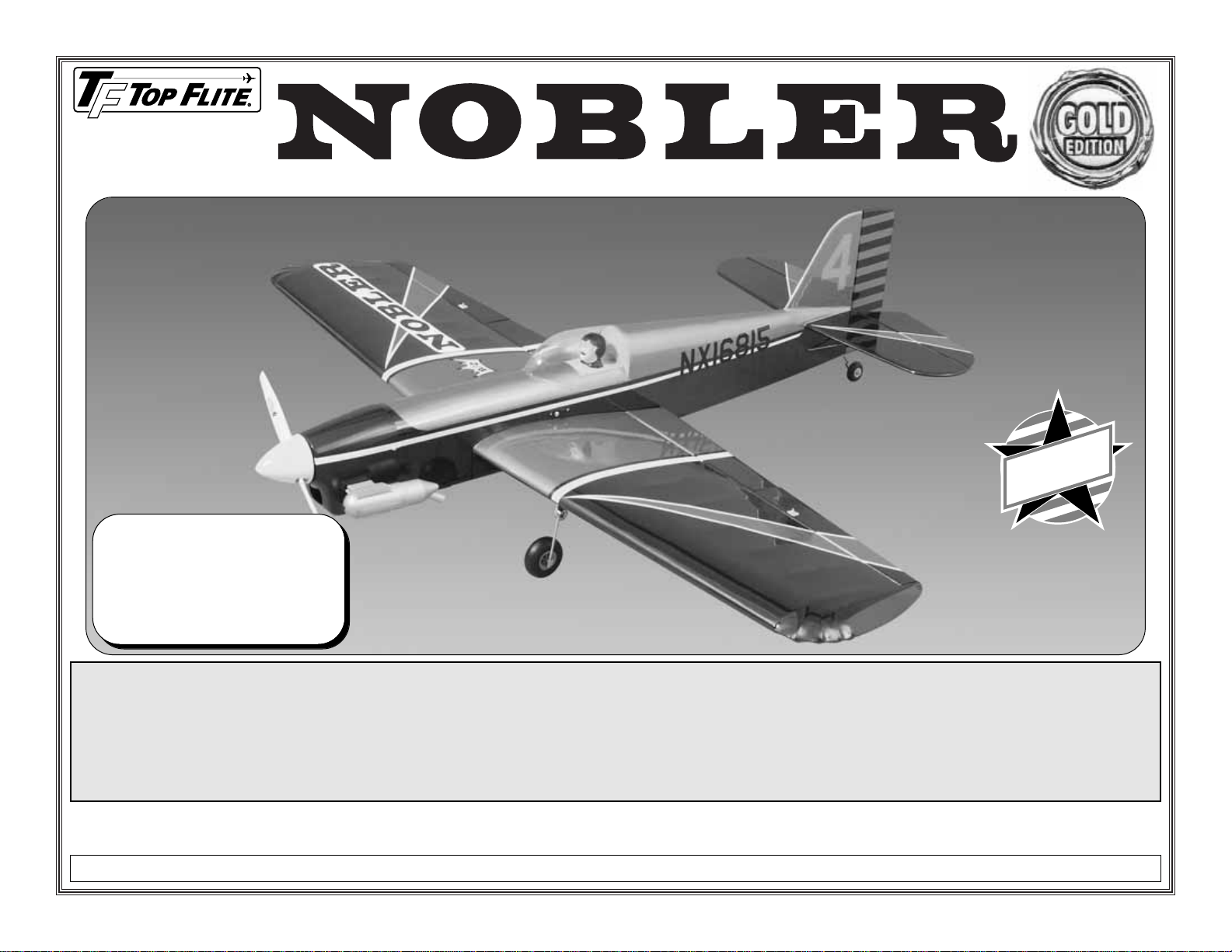
Wingspan: 51 in [1295.4 mm]
Wing Area: 550 sq in [35.5 sq dm]
Weight: 3-1/2 to 5-1/2 lb. [1588-2495g]
Wing Loading: 14.7 - 23.0 oz/sq ft.
[44.8-70.2 g/sq dm]
Fuselage Length: 42-3/8 in [1076 mm]
™
MADE IN
USA
Page 2
TABLE OF CONTENTS
INTRODUCTION . . . . . . . . . . . . . . . . . . . . . . . .2
PRECAUTIONS . . . . . . . . . . . . . . . . . . . . . . . . .3
DECISIONS YOU MUST MAKE . . . . . . . . . . . . .3
Engine selection . . . . . . . . . . . . . . . . . . . . . . . . .3
Retractable landing gear . . . . . . . . . . . . . . . . . . .3
Flaps . . . . . . . . . . . . . . . . . . . . . . . . . . . . . . . . .4
NOTES FROM THE DESIGNER . . . . . . . . . . . . .4
OTHER ITEMS REQUIRED . . . . . . . . . . . . . . . .5
Building supplies . . . . . . . . . . . . . . . . . . . . . . . . .5
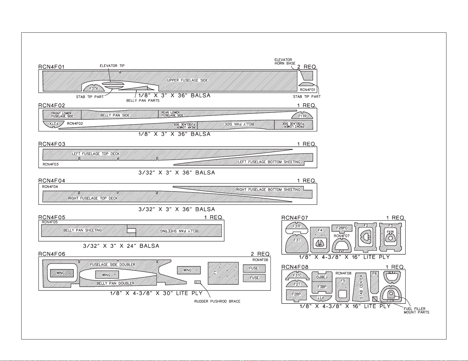
DIE-CUT PATTERNS . . . . . . . . . . . . . . . . . .6 & 7
Tools . . . . . . . . . . . . . . . . . . . . . . . . . . . . . . . . .8
IMPORTANT BUILDING NOTES . . . . . . . . . . . .8
GET READY TO BUILD . . . . . . . . . . . . . . . . . . .9
BUILD THE TAIL SURFACES . . . . . . . . . . . . . . .9
Build the stabilizer . . . . . . . . . . . . . . . . . . . . . . .9
Build the elevators . . . . . . . . . . . . . . . . . . . . . .11
Build the vertical fin . . . . . . . . . . . . . . . . . . . . .12
Build the rudder . . . . . . . . . . . . . . . . . . . . . . . .13
Hinge the elevators and rudder . . . . . . . . . . . . .13
BUILD THE FUSELAGE . . . . . . . . . . . . . . . . . .14
Prepare the fuselage sides . . . . . . . . . . . . . . . .14
Frame the fuselage . . . . . . . . . . . . . . . . . . . . . .16
Install the pushrods and servos . . . . . . . . . . . . .18
Install the receiver . . . . . . . . . . . . . . . . . . . . . . .21
Finish the fuselage . . . . . . . . . . . . . . . . . . . . . .22
BUILD THE WING . . . . . . . . . . . . . . . . . . . . . .24
Build the right panel . . . . . . . . . . . . . . . . . . . . .24
Build the wing tips . . . . . . . . . . . . . . . . . . . . . . .30
Build the ailerons . . . . . . . . . . . . . . . . . . . . . . .30
Build the flaps . . . . . . . . . . . . . . . . . . . . . . . . . .31
Hinge the ailerons and flaps . . . . . . . . . . . . . . .32
Join the panels . . . . . . . . . . . . . . . . . . . . . . . . .32
Mount the servos in the wing . . . . . . . . . . . . . .33
FINAL CONSTRUCTION . . . . . . . . . . . . . . . . .35
Mount the wing to the fuselage . . . . . . . . . . . . .35
Mount the stab and fin . . . . . . . . . . . . . . . . . . .38
Mount the fuel tank . . . . . . . . . . . . . . . . . . . . . .39
Rough sand the model . . . . . . . . . . . . . . . . . . .39
Install the landing gear . . . . . . . . . . . . . . . . . . .39
Mount the engine . . . . . . . . . . . . . . . . . . . . . . .41
Install the engine cowl . . . . . . . . . . . . . . . . . . . .41
Balance the airplane laterally . . . . . . . . . . . . . .43
Prepare the model for covering . . . . . . . . . . . . .43
FINISHING . . . . . . . . . . . . . . . . . . . . . . . . . . . .43
Cover with MonoKote . . . . . . . . . . . . . . . . . . . .43
Covering sequence . . . . . . . . . . . . . . . . . . . . . .44
Painting . . . . . . . . . . . . . . . . . . . . . . . . . . . . . .44
Join the control surfaces . . . . . . . . . . . . . . . . . .44
FINISHING TOUCHES . . . . . . . . . . . . . . . . . . .46
GET YOUR MODEL READY TO FLY . . . . . . . .46
Balance your model . . . . . . . . . . . . . . . . . . . . .46
Final hookups and checks . . . . . . . . . . . . . . . . .47
Control surface throws . . . . . . . . . . . . . . . . . . .48
PREFLIGHT . . . . . . . . . . . . . . . . . . . . . . . . . . .48
Identify your model . . . . . . . . . . . . . . . . . . . . . .48
Charge your batteries . . . . . . . . . . . . . . . . . . . .48
Balance your propeller . . . . . . . . . . . . . . . . . . .48
Find a safe place to fly . . . . . . . . . . . . . . . . . . .48
Ground check your model . . . . . . . . . . . . . . . . .48
Range check your radio . . . . . . . . . . . . . . . . . .48
Checklist . . . . . . . . . . . . . . . . . . . . . . . . . . . . . .49
ENGINE SAFETY PRECAUTIONS . . . . . . . . . .49
AMA SAFETY CODE . . . . . . . . . . . . . . . . . . . .50
FLYING . . . . . . . . . . . . . . . . . . . . . . . . . . . . . .50
Takeoff . . . . . . . . . . . . . . . . . . . . . . . . . . . . . . .50
Flight . . . . . . . . . . . . . . . . . . . . . . . . . . . . . . . .50
Landing . . . . . . . . . . . . . . . . . . . . . . . . . . . . . .50
TWO-VIEW DRAWING . . . . . . . . . . . .back cover
Your R/C Nobler is not a toy, but a sophisticated
working model that functions very much like an
actual airplane.Because of its realistic performance,
if you do not assemble and operate y our R/C Nobler
correctly, you could possibly injure yourself or
spectators and damage property.
To make your R/C modeling experience totally
enjoyable, get assistance with assembly and
your first flights from an experienced,
knowledgeable modeler. You’ll learn faster and
avoid risking your model before you’re truly ready to
solo. Your local hobby shop has information about
flying clubs in your area whose membership
includes qualified instructors.
You can also contact the Academy of Model
Aeronautics (AMA), which has more than 2,500
chartered clubs across the countr y.We recommend
you join the AMA which will insure you at AMA club
sites and events. AMA Membership is required at
chartered club fields where qualified flight
instructors are available.
Contact the AMA at the address or toll-free phone
number below.
Academy of Model Aeronautics
5151 East Memorial Drive
Muncie, IN 47302
(800) 435-9262
Fax (765) 741-0057
or via the Internet at: http://www.modelaircraft.org
INTRODUCTION
Congratulations and thank you for purchasing the
Top Flite
Gold 30th Anniversary Edition
R/C
Nobler. We are sure you are eager to build and fly
your R/C Nobler, just as we were eager to build and
fly our prototypes.
The original R/C Nobler was popular in the early 1970’s
and had a reputation for being highly maneuverable
and aerobatic. It was a short coupled model, which
enhances snap rolls and tumbling type maneuvers.
The new Gold 30th Anniversary Edition R/C Nobler
retains all of the original flight characteristics, and
builds on them with the use of today's computer radio
PRO TECT YOUR MODEL,
YOURSELF & OTHERS
FOLLO W THESE IMPORT ANT
SAFETY PRECAUTIONS
- 2 -
Page 3
systems.The model has been engineered to allow the
installation of up to 7 servos, as well as retractable
landing gear.
Well, this should be enough to get your juices
flowing, so get your other projects off your
workbench, say goodbye to your significant other for
a while and...keep reading!
Please inspect all parts carefully before you
start to build! If any parts are missing, broken or
defective, or if you have any questions about
building or flying this model, please call us at
(217) 398-8970 or e-mail us at:
pr
oductsupport@topflite.com.
We’ll be glad to help. If you are calling for
replacement parts, please look up the part
numbers and have them ready when you call.
PRECAUTIONS
1.You must build the plane according to the plan and
instructions. Do not alter or modify the model, as
doing so may result in an unsafe or unfly ab le model.In
a few cases the plan and instructions may differ
slightly from the photos. In those instances the
plan and written instructions are correct.
2. You must take time to build straight, true
and strong.
3. You must use a proper R/C radio that is in first
class condition, the correct sized engine and
correct components (fuel tank, wheels, etc.)
throughout your building process.
4. You must properly install all R/C and other
components so that the model operates properly on
the ground and in the air.
5. You must test the operation of the model before
every flight to insure that all equipment is operating
and you must make certain that the model has
remained structurally sound.
6. If you are not already an experienced R/C pilot,
you must fly the model only with the help of a
competent, experienced R/C pilot.
Remember: Take your time and follow
instructions to end up with a well-built model
that is straight and true.
ENGINE SELECTION
Recommended engine size:
.25 to .46 cu. in. [4.1 to 7.5cc] 2-stroke
.40 to .52 cu. in. [6.5 to 8.5cc] 4-stroke
Your Top Flite Gold 30’th Anniversary Edition R/C
Nobler will perform well with any of the engines
within the recommended range, but will handle
best with engines closer to the higher end of the
recommended size range. The inexpensive O.S.
.40 LA has more than adequate power to perform
even the most demanding aerobatic maneuvers.
The included Great Planes Adjustable Engine
Mount will hold a range of engines from .25 cu.in.
2-stroke through .52 cu. in. 4-stroke.
RETRACTABLE LANDING GEAR
You may build your R/C Nobler either with fixed or
retractable landing gear. All the hardware you
need for fixed gear is supplied with this kit. We
also provide detailed instructions on how to install
retractable landing gear available from Great
Planes.The Great Planes mechanical retractable
landing gear recommended and shown in this
manual is light, inexpensive and strong. You may
choose to use another type of retract but it is up
to you to make modifications required to fit them.
(continued on page 4)
DECISIONS YOU MUST MAKE
NOTE: We, as the kit manufacturer, provide you
with a top quality kit and great instructions, but
ultimately the quality and flyability of your finished
model depends on how you build it;therefore, we
cannot in any way guarantee the performance of
your completed model, and no representations
are expressed or implied as to the performance or
safety of your completed model.
- 3 -
Page 4

NOTES FROM THE DESIGNER
When I became interested in modeling as a kid the
Top Flite Nobler was a very popular control line
model. I built and flew several of them and still have
many fond memories from that time, almost fifty
years ago.
When the Top Flite R/C Nobler was introduced I just
had to have one. That was thirty years ago, and it
was a great flying model in its day. Now I design
models for Top Flite and jumped at the chance to
redesign the model for the anniversary re-release of
this classic model. Isn’t this hobby great!
While the original R/C Nobler was a great flying
model, it did have a number of problems. It was
difficult to build, had terrible die-cutting and required
a lot of sanding and shaping. It also had some
structural problems. We have tried hard to correct
these problems.You will note that the aft section of
the model and the tail feathers hav e been changed to
improve the flying characteristics.
The original R/C Nobler had a D-tube wing
construction, but the spar was just a 1/16” balsa web
- with nothing else, no spars. It was not uncommon
for the wing to fail during snap rolls.The new version
of the model also has a D-tube wing construction, but
it has top and bottom basswood spars with a die-cut
3/32” I-beam type web. The original model had balsa
block wing tips that needed to be carved and
sanded.The new version of the model has wing tips
built from die-cut parts, much like the control line
model did.
The fuselage of the original R/C Nobler was built
from die-cut sides with many balsa blocks added.
These blocks required considerab le carving, shaping
and sanding. The turtle deck had an annoying habit
of cracking, causing the tail feathers to loosen.The
new version of the model has no blocks at all. The
model has die-cut sides and formers that are then
sheeted. The turtle deck and tail section have been
redesigned and strengthened.
The tail feathers on the original R/C Nobler were
made from 1/4” sheet balsa and were a bit heavy .On
hard landings the weight of the tail feathers would
cause the turtle deck to crack at various glue joints.
The tail feathers on the new version are built-up for
lightness and strength from sticks that are then
sheeted with 1/16” balsa.
I did not enjoy building the original version of the
model. The die-cutting was bad, parts fit was poor
and it required a lot of carving and sanding. I hope
you find the new version fun to build. The die-cutting
is great and the parts fit is right on, thanks to modern
computer CAD design systems. And it takes only
about 15 minutes to sand the entire model! If you are
a quick builder it would be possib le to build the model
and have it ready to cover in a long weekend.
The original R/C Nobler had a fixed wing that could
not be removed from the fuselage, and could be a bit
difficult to transport and store.The new version of the
model has a removable wing held in place with three
nylon bolts.
While the original model required only four servos to
operate ailerons, rudder, throttle and elevators with
coupled flaps, the new version requires six servos.
You can also add a seventh servo for retractable
landing gear. That’s right, you can now build the
model with retractable main landing gear.
Our prototype models, with seven full size servos and
retractable landing gear weighed 5 lbs 8 oz, almost
exactly the same weight of the original model. The
structure of the new version is much lighter due to the
elimination of all the balsa blocks and also the built up
tail feathers.At the same time, it is also much stronger.
For Retractable Landing Gear you will need
these items (not included):
Great Planes Retracts (GPMQ2905)
Retract servo (FUTM0670 or HCAM0160)
(2) 2-1/4” [57mm] wheels (GPMQ4222)
(2) Nylon Clevis (GPMQ3800)
(2) 2-56 x 12” [305mm] pushrod, threaded one
end (GPMQ3750)
(2) Screw-Lock connectors (GPMQ3870)
(8) #4 x 3/8”[9.5mm] flat head sheet metal screws
FLAPS
Your R/C Nobler is designed to incorporate flaps.
You must build these flaps, but you do not have to
make them operational. If you do not want
operational flaps simply glue them into place. As
the wing is removable, the flaps cannot be
mechanically coupled to the elevator as the
original R/C Nobler could.
For normal (independent) flap operation, only one
servo is required.This allows the flaps to be used
as normal flaps as well as for elevator to flap
mixing with a computer radio system.
Slight trim changes are needed when flaps are
extended.The trim corrections are discussed later
in the control surface throws section and you will
find more information on the flaps in the
Flying
section and the radio installation section.
For Flaps, you will need the following
additional item:
one standard servo.
- 4 -
Page 5

Radio installation
The radio installation can be as simple as five standard
servos - or as challenging as seven servos that must be
fitted in a confined space.Pay very close attention to the
instructions and it will all fit easily. Drift off on your own
if you want, but be prepared to spend a lot of time
getting things to fit properly.
Nose heavy/Tail heavy
Most models require some nose weight to balance
properly. This one requires tail weight! The built up
tail feathers are light yet very strong. The tail is also
very short, resulting in a model that is slightly nose
heavy. If you power the model with a .46 size glow
engine you will need about 1 oz of lead on the tail.
Engine size
This model can be flown on a .25 size engine, but why. With an O.S. .46 FX, nine servos and retracts
the model weighs close to 5-1/2 lbs. That gives a
wing loading of 23.0 oz/sq ft.The engine will produce
more than six lbs of thrust if it is properly broken-in.
Think about those numbers for a minute.
Start building! Build light!!
OTHER ITEMS REQUIRED
These are additional items you will need to complete
your R/C Nobler that are
not included
with your kit.
Order numbers are in parentheses (GPMQ4130).
Our exclusive brand is listed where possible: TOP is
the Top Flite brand, GPM is the Great Planes
®
brand, and HCA is the Hobbico®brand.
❏ 4 to 6 channel radio with 5 to 7 servos
❏ 5 standard ser vos for Ailerons (2), Elevator,
Rudder, Throttle (Stationary flaps).
or:
6 standard servos for ailerons (2), Elevator,
Rudder, Throttle, Flaps (Electronic
Elevator to Flap coupling)
or:
7 servos gives above plus retractable landing gear.
(Note:Recommend 6 standard and 1 retract servo)
❏ (1) ‘Y’ Connector for aileron, (if only one aileron
channel is used)
Note:‘Y’ connector not needed if ailerons, are
mixed to separate receiver channels.
❏ (2) 12” [305mm] Ser vo extensions for
aileron servos
❏ (1-4) 6” [152mm] Ser vo extensions (1 or 2 for
ailerons, 1 for flaps, 1 for retracts)
(Simplifies wing installation at flying field - optional)
❏ Switch/charge plug mount (GPMM1000)
❏ (2) 2-1/2” [63.5mm] Main Wheels (GPMQ4223)
or:
(2) 2-1/4” [57mm] Main wheels (GPMQ4222) with
retracts
❏ 1-1/4” [31.8mm] Tail wheel (GPMQ4242)
❏ Optional retracts (GPMQ2905)
❏ 10 oz. [300cc] Fuel tank (GPMQ4104)
❏ Silicone fuel tubing (GPMQ4131)
❏ Fuel filler valve (GPMQ4160)
❏ 2-1/2” [63.5mm] Spinner (GPMQ4521, black)
❏ 1/4” [6.4mm]R/C Foam rubber padding
(HCAQ1000)
❏ 2 rolls Top Flite Super MonoKote
®
covering, see
Finishing
on page 43
❏ 1 roll Top Flite Super MonoKote trim color
❏ Paint, see
Finishing
on page 43
❏ Propellers (see engine instructions)
BUILDING SUPPLIES
Here’s a list of supplies you should have on hand
while you’re building. Some of these are optional.
Use your own experience to decide what you need.
We recommend Great Planes Pro CA and Epoxy.
Glue/Filler
❏ 2 oz. [60g] Thin CA (GPMR6003)
❏ 2 oz. [60g] Medium CA+ (GPMR6009)
❏ 1 oz. [30g] Thick CA- (GPMR6014)
❏ CA Accelerator (GPMR6034)
❏ CA Debonder (GMPR6039)
❏ CA Applicator Tips (HCAR3780)
❏ 30-minute (GPMR6047) or 45-minute
(GPMR6048) epoxy
❏ 6-minute epoxy (GPMR6045)
❏ Pro™Wood Glue (GPMR6161)
❏ Microballoons (TOPR1090)
❏ Milled Fiberglass (GPMR6165)
❏ Lightweight Hobby Filler (Balsa Color,
HCAR3401)
❏ Auto body filler (Bondo
®
or similar)
❏ Denatured or Isopropyl Alcohol (to clean up
excess epoxy)
(continued on page 8)
- 5 -
Page 6
- 6 -
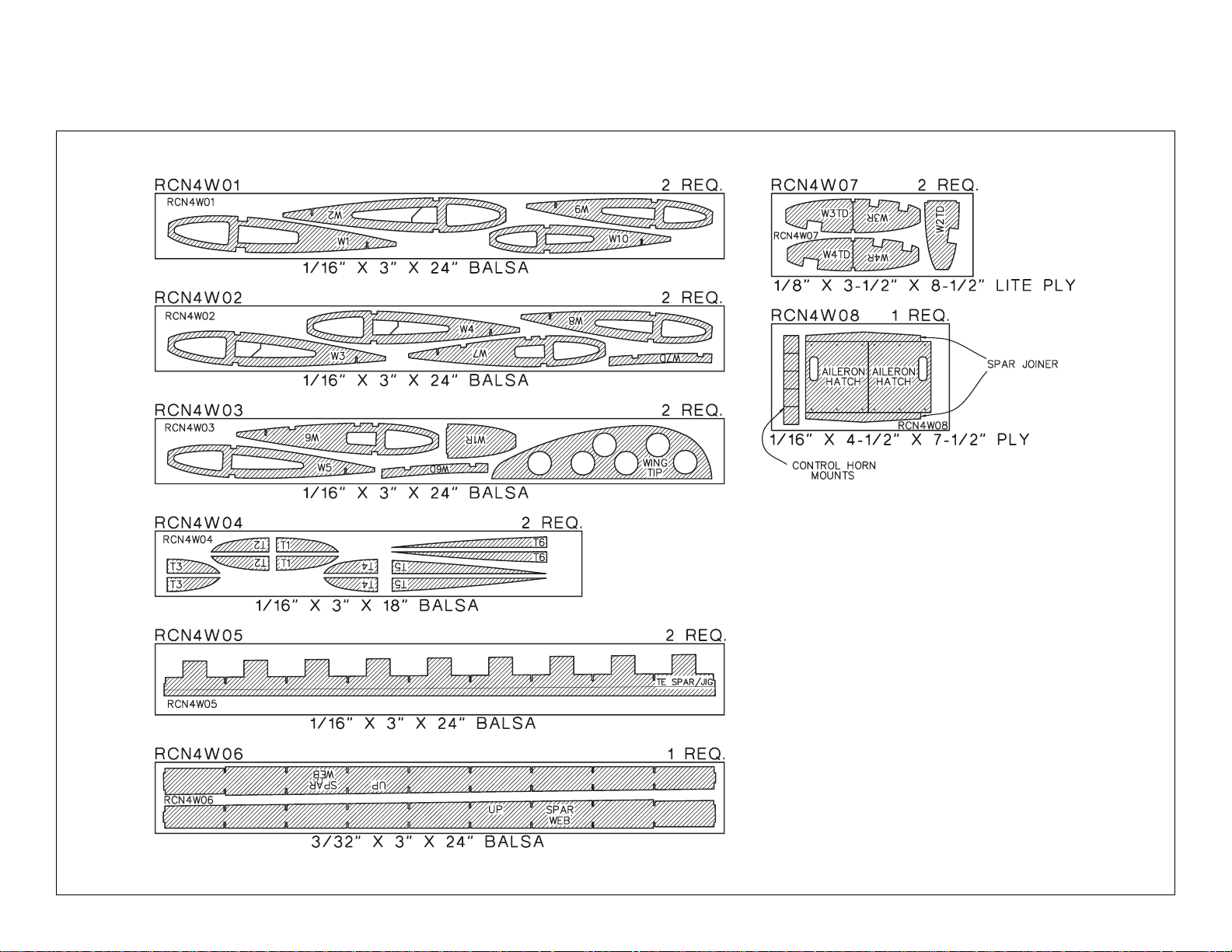
DIE-CUT PATTERNS
IMPORTANT
Do not remove the wing ribs or other wing parts from the die-cut sheets until instructed to do so.
Page 7
- 7 -
DIE-CUT PATTERNS
Page 8
Tools
❏ #11 Blades (HCAR0311) -100 qty.
❏ Single Edge Razor Blades (HCAR0312) -100 qty.
❏ Razor Plane (MASR1510)
❏ Hobbico Builder’s Triangle (HCAR0480)
❏T-Pins (HCAR5100) small, (HCAR5150) medium,
(HCAR5200) large
❏ Drill Bits: 1/16” [1.6mm], 3/32” [2.4mm],
1/8” [3.1mm], 5/64” [2mm], 7/64” [2.8mm],
9/64” [3.6mm], 5/32” [4mm], 11/64” [4.4mm],
3/16” [4.8mm], 7/32” [5.6mm], 1/4” [6.4mm]
❏ 1/4-20 Tap and dr ill (GPMR8105)
❏ 10-32 Tap and dr ill (GPMR8104)
❏ 6-32 Tap and dr ill (GPMR8102)
❏ Tap wrench (GPMR8120)
❏ Kyosho®curved plastic cutting scissors
(KYOR1010)
❏ Great Planes Plan Protector (GPMR6167) or
waxed paper
❏ Masking T ape
❏ Easy–Touch™ Bar Sanders*
❏ Precision Z-Bend pliers (GPMR8025)
Recommended Covering
Tools/Accessories
❏ 21st Centur y Sealing Iron (COVR2700)
❏ 21st Centur y Cover Sock (COVR2702)
or:
❏ Top Flite Sealing Iron (TOPR2100)
❏ Top Flite Hot Sock™(TOPR2175)
and
❏ Top Flite Heat Gun (TOPR2000)
❏ Top Flite Trim Seal Tool (TOPR2200)
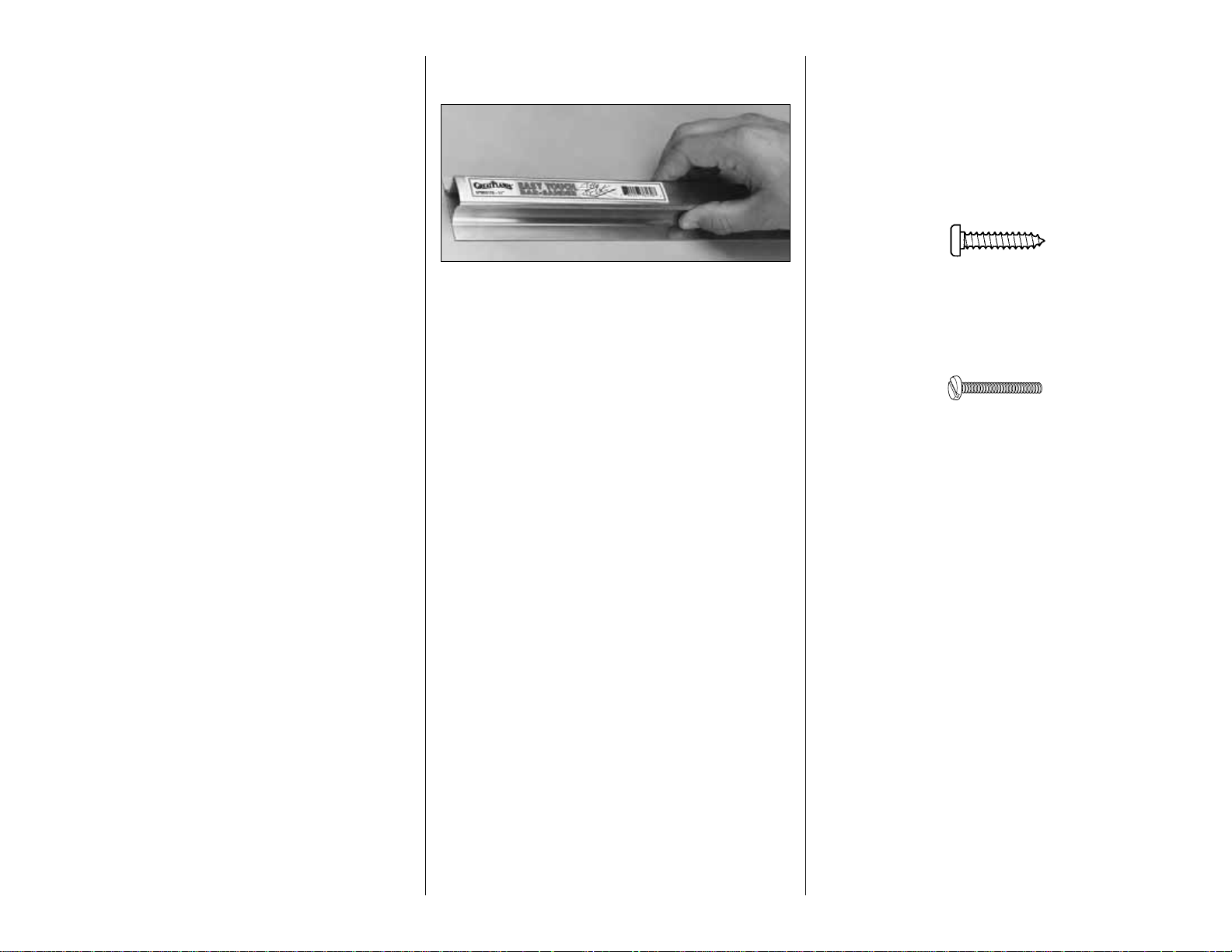
EASY-TOUCH™BAR SANDER
A flat, durable, easy to handle sanding tool is a
necessity for building a well finished model. Great
Planes makes a complete range of Easy-Touch Bar
Sanders (patented) and replaceable Easy-Touch
Adhesive-backed Sandpaper. While building the
R/C Nobler we used two 5-1/2" Bar Sanders and two
11" Bar Sanders equipped with 80-grit and 150-grit
Adhesive-backed Sandpaper.
Here’s the complete list of Easy-Touch Bar Sanders
and Adhesive Backed Sandpaper:
5-1/2" Bar Sander (GPMR6169)
11" Bar Sander (GPMR6170)
22" Bar Sander (GPMR6172)
33" Bar Sander (GPMR6174)
44" Bar Sander (GPMR6176)
11" Contour Multi-Sander (GPMR6190)
12’ roll of Adhesive-backed:
80-grit sandpaper (GPMR6180)
150-grit sandpaper (GPMR6183)
180-grit sandpaper (GPMR6184)
220-grit sandpaper (GPMR6185)
Assortment pack of 5-1/2" strips (GPMR6189)
We also use Top Flite 320-grit (TOPR8030, 4 sheets)
and 400-grit (TOPR8032, 4 sheets) wet-or-dry
sandpaper for finish sanding.
IMPORTANT BUILDING NOTES
There are two types of screws used in this kit:
Sheet metal screws are designated by a number
and a length.
For example #6 x 3/4" long [19.1mm]
Machine screws are designated by a number,
threads per inch, and a length.
For example 4-40 x 3/4" long [19.1mm]
•
When you see the term
test fit
in the instructions,
it means that you should first position the part on
the assembly without using any glue, then
slightly modify or
custom fit
the part as necessar y
for the best fit.
•
Whenever the term
glue
is written you should rely
upon your experience to decide what type of glue
to use. When a specific type of adhesive works
best for that step, the instructions will tell y ou what
glue is recommended.
•
Whenever just
epoxy
is specified you may use
either
30-minute epoxy or6-minute epoxy. When
30-minute epoxy is specified, it is highly
recommended that you use only 30-minute (or
45-minute) epoxy because you will need the
working time and/or the additional strength.
•
Occasionally we refer to the
top
or
bottom
of the
model or upor
down
. To avoid confusion, the
top
or
bottom
of the model is as it would be when the
airplane is right side up and will be referred to as
the top even if the model is upside-down during
that step,
i.e.
the top main spar is always the top
- 8 -
Page 9
main spar even if the wing is upside-down when
you are working on it. Similar ly,
move the former
up
means move the former toward the top of the
fuselage even if the fuselage is upside-do wn when
you are working on it.
•
When you get to each step, read that step
completely through to the end before you begin.
Frequently there is important information or a note
at the end of the step that you need to know before
you start.
•
Photos and sketches are placed before the
step they refer to .Frequently you can study photos in
following steps to get another view of the same parts.
GET READY TO BUILD
1. Unroll the plan sheets. Roll them inside out so
they lie flat.
2.Remove all the parts from the box.Use a ballpoint
pen (not a felt tip pen) to lightly write the name or
size on each piece so you can identify it later. Use
the
die-cut patterns
on pages 6 and 7 to identify and
mark the die-cut parts before you remove them from
their die sheets. Many of the parts already have
numbers stamped on them, but in some cases the
number is located alongside the parts or only on the
die drawings in the manual.Do not remove the die-cut
parts until instructed to do so. If a part is difficult to
remove, don’t f orce it out b ut cut around it with a hobb y
knife and a #11 blade.After you remove the parts from
their die sheets, lightly sand the edges to remove
slivers or die-cutting irregularities. Save some of the
larger scraps of wood.
3. Separate the parts into groups such as stab, fin,
wing, and fuse. Store smaller parts in zipper-top
food storage bags.
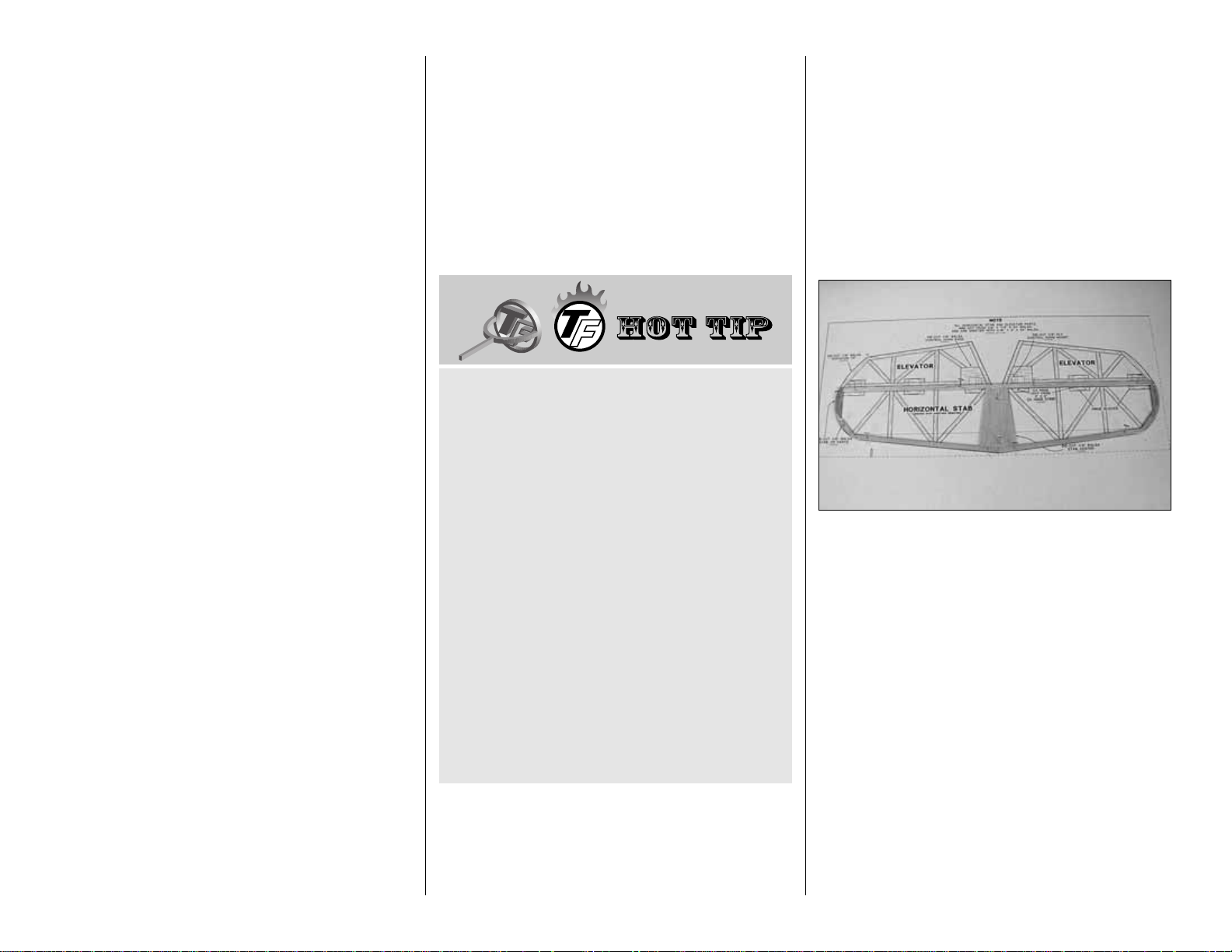
BUILD THE T AIL SURF ACES
Use the
Hot Tip
that follows to cut the 1/8” x 1/4” x
24” [3.2 x 6.4 x 610mm] sticks for the framework of
the stab, elevators, fin and rudder. This framework
will then be sheeted with 1/16” x 3” x 24” [1.6 x 76 x
610mm] balsa.
BUILD THE ST ABILIZER
❏ 1. Cut the stab plan along the dashed line and
tape it to your building board. Cover the plan with
Plan Protector or wax paper.
❏2.Cut the stab TE from a hard 1/8”x 1/4” x 24”[3.2
x 6.4 x 610mm] balsa stick and pin it in position over
the plan.
❏ 3. Pin the die-cut 1/8” [3.2mm] ply stab center in
position. Similarly, pin the die-cut 1/8” [3.2mm] balsa
stab tip parts in position. Do not glue until later.
❏ 4. Cut both stab LE pieces from another hard 1/8”
x 1/4” x 24” [3.2 x 6.4 x 610mm] balsa stick and pin
them in position. Do not glue until later.
HOW T O CUT THE STICKS
There are ten 1/8”x 1/4” x 24”[3.2 x 6.4 x 610mm]
sticks supplied for building the stab, elevators, fin
and rudder. There are ample sticks supplied for
building these parts. Do not use the 30” [762mm]
sticks that are used for building the wing.
Use the hardest sticks for building the framework
of the stab and fin.The softer sticks can be used
for the ribs and diagonal pieces, and for the
elevators and rudder.
Cut the longest parts from the sticks first, using
the remainder for the shorter pieces. We have
found that a new single edge razor blade makes
the best cuts with a minimum of crushing.
We found it fastest to cut all of the required parts
at one time.Others may prefer to cut each part as
it is needed.
- 9 -
Page 10
❏5.Cut the stab ribs, diagonals and hinge blocks
from soft 1/8” x 1/4” x 24” [3.2 x 6.4 x 610mm] balsa
sticks and place them into position. Glue all of the
parts together with thin CA where they join each
other - refer to the
Hot Tip
that follows.
❏ 6. After the CA has cured, remove the pins from
the stab. Use a sanding block with 150-grit
sandpaper to sand the stab flat.
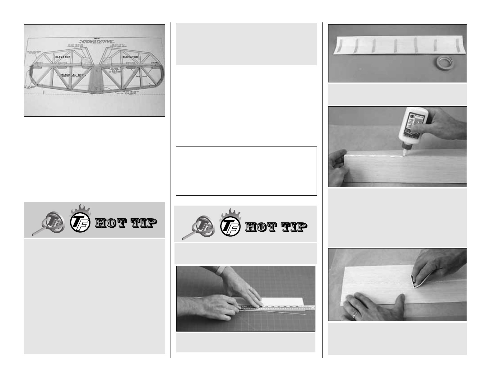
❏ 7. Use the
Hot Tip
that follows (or your own
method) to glue two 1/16" x 3" x 24" [1.6 x 76 x
610mm] balsa sheets together to make a 1/16" x 6"
x 24" [1.6 x 152 x 610mm] sheet for one of the stab
skins.Use the two hardest sheets supplied in the kit.
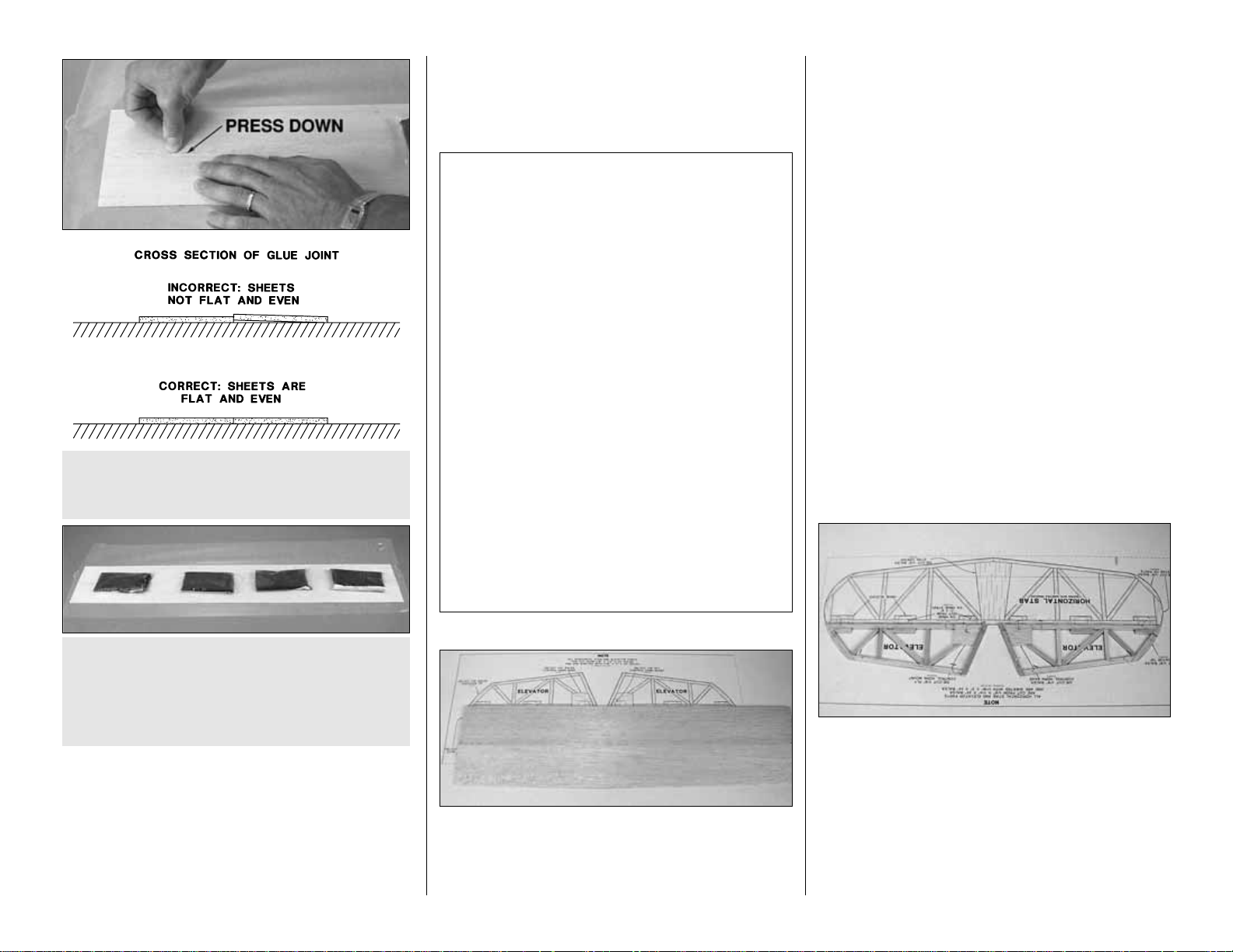
D.Lay the sheets on your workbench covered with
wax paper.Use a credit card or something similar
as a squeegee to simultaneously press the sheets
flat as you wipe the glue from the seam.
C. Turn the sheets over and apply slow drying
glue like Great Planes Pro aliphatic resin to the
joining edges.Some prefer to use CA, but it is not
recommended in this
Hot Tip
because CA does
not allow enough working time to align the sheets
and it is much harder than the balsa, making
sanding difficult.
B. Use masking tape to tightly tape the trued
edges of the sheets together.
A. Use a straightedge to true one edge of two
balsa sheets.
HOW TO MAKE THE STAB SKINS
Top Flite selects balsa that is intended for
sheeting.Occasionally , a f ew of these sheets ma y
have a small nick or split near the ends. If your kit
contains a few of these sheets, arr ange them and
glue them together so the defects will not
interfere with the final shape of your skin.
When you install the tip on the end of the CA
bottle, cut the large end of the tip to a depth of
about 1/4” [6.4mm]. Doing so will prevent the tip
from splitting and leaking when it is pressed onto
the bottle.
It can be difficult to control the application of thin
CA adhesives and get that one small drop that is
needed to glue a part. We have found a CA
applicator tip, available from Hobbico, to be very
useful. Frankly, we wonder how we ever got along
without them.
With these tips you will no longer have large b lobs
of CA that needs to be sanded away.Your supply
of CA will also last much longer. As the tip clogs
simply snip the clogged part off and keep using it.
Two of these tips are supplied with this kit. If you
like them their part number is HCAR3780 (6) and
are available in bulk BUKR0307 (200).
- 10 -
Page 11
Note: Some modelers tend to sand the sheeting too
much after it is applied to the structure, making thin
spots where fingers can easily go through. By
following the procedure abov e (specifically, by aligning
the joined edges of the sheets as shown in step E),
little sanding should be required. Most of the sanding
that isrequired should be done before the sheeting is
glued in place. The only sanding that should be
required after the sheeting is glued to the structure is
final sanding with 320 or 400-grit sandpaper.
❏ 8. Use medium CA or aliphatic resin to glue the
stab skin to the top of the stab. Align the skin even
with the TE of the stab. Note that the sheeting is
positioned so that it overhangs one end of the stab.
❏ 9. After the glue dr ies, remove the stab from the
building board and trim the sheeting along the LE
and both tips. Save the leftover sheeting for use in
the next step.
❏ 10. Locate another hard sheet of 1/16" x 3" x 24"
[1.6 x 76 x 610mm] balsa. Use this sheet and the
leftover sheeting from the above step to make
another stab skin.
❏ 11. Turn the stab over and use a sanding block to
sand the un-sheeted side of the stab flat. Use
medium CA or aliphatic resin to glue the stab skin to
the stab.Align the skin even with the TE of the stab.
The sheeting is positioned so that it overhangs one
end of the stab.
❏ 12. After the glue dries, remove the stab from the
building board and trim the sheeting along the LE
and both tips. Save the leftover sheeting for use in a
later step.
BUILD THE ELEVATORS
❏ 1. Pin the die-cut 1/8” balsa control horn base
into position. Use 1/8" x 1/4" x 24" [3.2 x 6.4 x
610mm] soft balsa sticks to cut all of the parts for
both elevators. Pin them into position and glue the
parts together with thin CA where they join.
❏ 2. After the CA has cured, remove the pins from
both elevators. Use a sanding block with 150-grit
sandpaper to sand the elevators flat.
Here are a few other things to keep in mind
while sanding balsa sheeting:
1. Make sure you sand the sheets on a flat work
surface that is free from hardened drops of glue or
other imperfections that will damage your
sheeting.
2. Sand the sheeting only as much as required.
The inside of the sheeting needs to be sanded just
enough to remove excess glue and doesn’t have
to be perfectly flat or smooth.
3. Though more material can be removed by
sanding across the grain, this leaves scratches in
the balsa. Balsa sheeting should be sanded with
the grain—especially when finish-sanding.
4. If some of the glue joints are uneven, it may be
best just to leave them that way, rather than to
sand the sheets too thin. A slightly uneven glue
joint is preferable to paper-thin balsa.
F. Place weights on top of the sheet to hold it flat
while the glue dries.
G. After the glue dries, sand the sheets flat
and even.
E. Press the joining edges of the sheets down to
make sure they are even. This is important. Little
sanding will be required if the sheets are even.
-11-
Page 12
❏ 3. Use a soft 1/16" x 3" x 24" [1.6 x 76 x 610mm]
sheet of balsa to sheet the top of both elevators. Cut
a piece from the sheet for each elevator.Then, glue
it in place with medium CA or aliphatic resin. Save
the leftover sheeting for use later.
❏ 4.After the glue dries, remove both elevators from
the building board and trim the sheeting along the
TE, LE and tips.
❏ 5.Turn the elevators o ver and use a sanding block
to sand the un-sheeted side of them flat. Locate
another soft sheet of 1/16" x 3" x 24" [1.6 x 76 x
610mm] balsa and cut a piece from the sheet for
each elevator. Use medium CA or aliphatic resin to
glue the sheet to the elevators.
❏ 6. After the glue dr ies, remove the elevators from
the building board and trim the sheeting along the
TE, LE and tips.
❏ 7. Locate a die-cut 1/16" [1.6mm] ply control
horn mount. Using the plan as a reference, position
the control horn mount on the bottom of the right
elevator and mark its location. Cut along the lines
you marked and remove the balsa to inset the
mount. Glue the mount into the elevator.
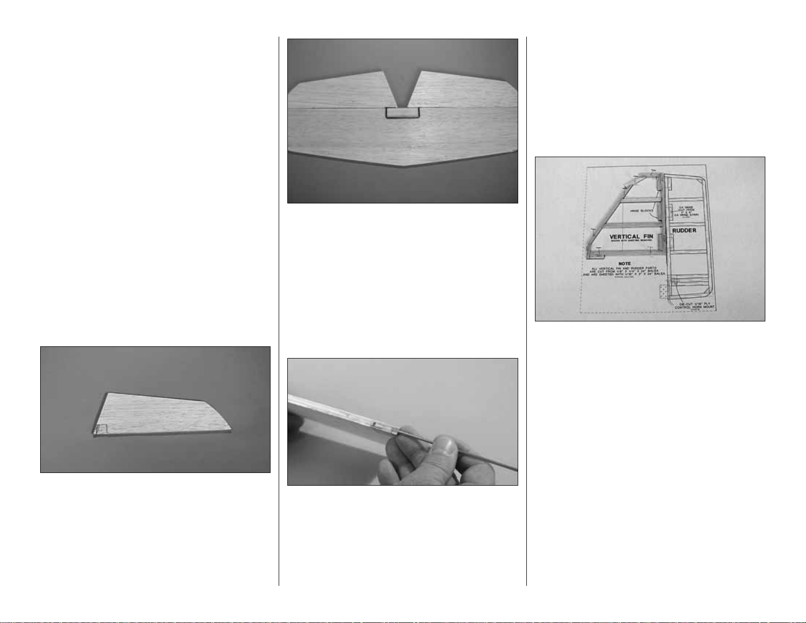
NOTE:Be sure to make a right elevator as shown in
the above photo.
❏8.Use a file or a rotary tool with a cut-off wheel to
remove sharp edges or burrs on the ends of the
elevator joiner wire.Position the ele v ator joiner wire
on the top of the stab as shown in the photo. Align
the elevators with the stab and mark the leading
edge of the elevators where the
arm
portion of the
joiner wire will enter the elevators. The joiner wire
should be centered between the elevators as shown
on the plan.
❏ 9. Drill a 3/32" [2.4mm] hole into the leading edge
of both elevators at the marks you made. Be sure to
drill the hole on the centerline of the leading edge.
Cut a groove in the leading edge of both elevators to
accommodate the joiner wire.
Hint: Use a 3/32" [2.4mm] brass tube sharpened at
one end to cut the grooves.
BUILD THE VERTICAL FIN
❏ 1. Cut the vertical fin plan along the dashed line
and tape it to your building board.Cover the fin plan
with Plan Protector or wax paper.
❏ 2. Cut the fin TE from a hard 1/8" x 1/4" x 24" [3.2
x 6.4 x 610mm] balsa stick and pin it in position over
the plan.
❏ 3. Cut the fin LE and the top and bottom par ts
from the remainder of the balsa stick and pin them in
position. Do not glue until later.
❏ 4. Cut the fin ribs and hinge blocks from soft
1/8" x 1/4" x 24" [3.2 x 6.4 x 610mm] balsa sticks and
place them into position. Glue all of the parts
together with thin CA where they join each other.
❏ 5. After the CA has cured, remove the pins from
the fin. Use a sanding block with 150-grit sandpaper
to sand the fin flat.
-12-
Page 13
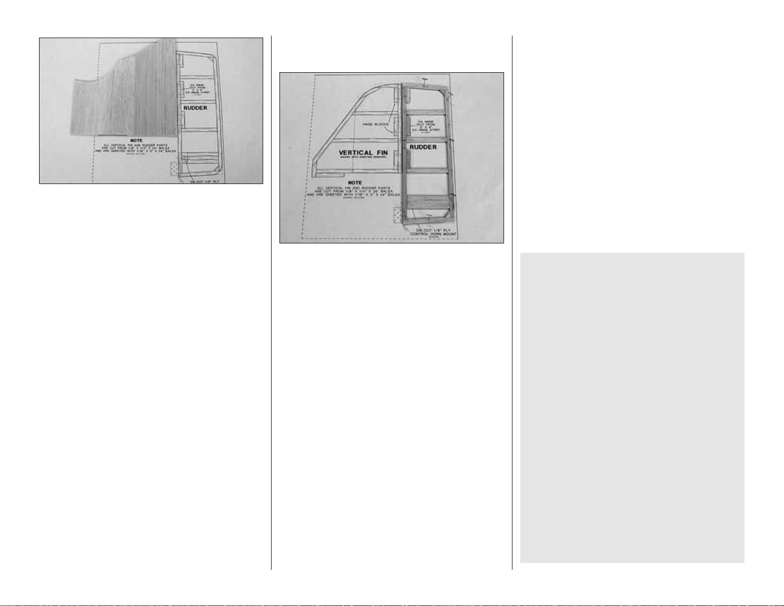
❏ 6. Locate the leftover 1/16" [1.6mm] balsa
sheeting used to sheet the stab and elevators. Use
this material to make two fin skins similar to the
above photo.
❏7.Use medium CA or aliphatic resin to glue one of
the fin skins to the left side of the fin. Align the skin
even with the TE and bottom of the fin.
❏ 8. After the glue dries, remove the fin from the
building board and trim the sheeting along the LE,
TE, bottom and top.
❏ 9. Turn the fin over and use a sanding block to
sand the un-sheeted side of the fin flat. Use medium
CA or aliphatic resin to glue the second fin skin to the
fin. Align the sheet even with the TE and bottom of
the fin.
❏ 10. After the glue dries, remove the fin from the
building board and trim the sheeting along the LE,
TE, bottom and top.
BUILD THE RUDDER
❏ 1. Use 1/8" x 1/4" x 24" [3.2 x 6.4 x 610mm] soft
balsa sticks to cut all of the parts for the rudder. Pin
them into position and glue the parts together with
thin CA where they join.
❏ 2. After the CA has cured, remove the pins from
the rudder. Use a sanding block with 150-grit
sandpaper to sand the rudder flat.
❏ 3. Use a soft 1/16" x 3" x 24" [1.6 x 76 x 610mm]
sheet of balsa to cut a piece to sheet the left side of the
rudder. Glue this sheet in place with medium CA or
aliphatic resin. Save the leftover sheeting for use later.
❏ 4.After the glue dries, remove the rudder from the
building board and trim the sheeting along the TE,
LE and tips.
❏ 5.Turn the rudder over and use a sanding bloc k to
sand the un-sheeted side flat. Use the remainder of
the sheeting to cut a piece for the other side of the
rudder.Use medium CA or aliphatic resin to glue this
sheet to the rudder.
❏ 6.After the glue dries, remove the rudder from the
building board and trim the sheeting along the TE,
LE and tips.
❏ 7. Locate a die-cut 1/16" [1.6mm] ply control
horn mount. Using the plan as a reference, position
the control horn mount on the left side of the rudder
and mark its location.Cut along the lines you marked
and remove the balsa to inset the mount. Glue the
mount into the rudder.
HINGE THE ELEVATORS
AND RUDDER
IMPORTANT NOTES
ABOUT CA HINGES
This kit is supplied with a CA hinge material
consisting of a 3-layer lamination of Mylar and
polyester. It is specially made for hinging model
airplane control surfaces.When properly installed,
this type of CA hinge provides the best
combination of strength, durability and easy
installation. We trust all of our Gold Edition
warbirds to these hinges, but it is essential to
install them correctly.Carefully follow the hinging
instructions in this manual for the best result.
The most common mistake made by modelers
when installing CA hinges is making the hinge
slots too tight, restricting the flow of CA to the
back of the hinges; or not using enough glue to
fully secure the hinge over its entire surface area.
This results in hinges that are only
tack glued
into
the hinge slots. The techniques for cutting the
hinge slots and gluing in the CA hinges (near the
end of the manual) have been developed to
ensure thorough and secure attachment.
-13-
Page 14
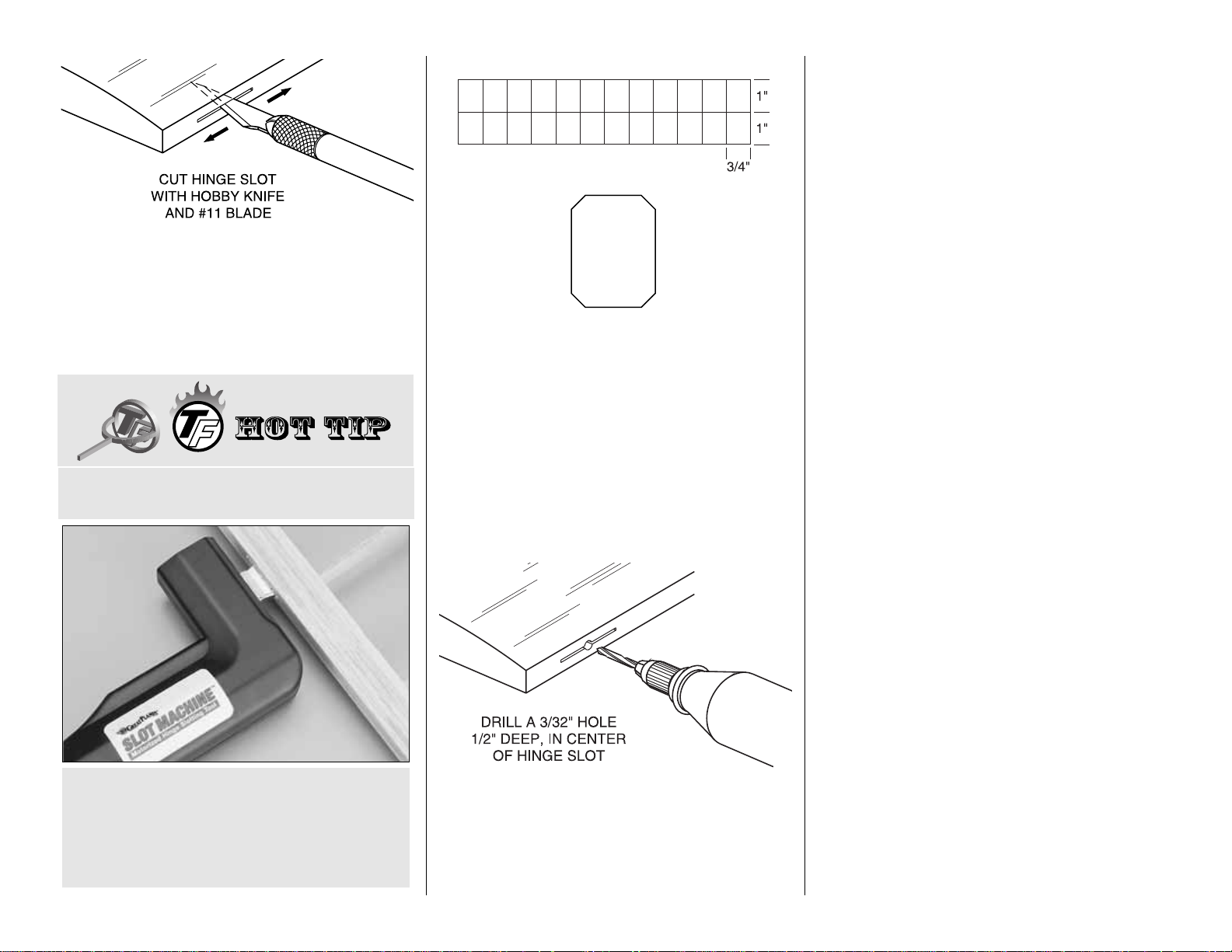
❏ 1. Use a straightedge to mark the centerline of
both elevators and the stab with a ballpoint pen.
Mark the location of the hinge slots on the elevators
and stab where shown on the plan. Cut the hinge
slots in the elevators and the stab along the
centerlines with a #11 blade.
❏ 2. Using the sketch above, cut nine hinges to a
size of 3/4" x 1" [19 x 25.4mm] from the CA hinge
strip supplied with this kit. Snip the corners off so
they go into the slots easier.
❏ 3.Test fit the hinges into the slots.If the hinges do
not slide into the slots easily, work your knife blade
back and forth in the slot a few times to pro vide more
clearance (it is really the back edge of the blade that
does the work here in widening the slot).
❏ 4. Drill a 3/32" [2.4mm] hole, 1/2" [12.7mm] deep
in the center of the hinge slots.Use a rotary tool with
a 3/32" [2.4mm] drill bit or a carbide cutter for the
best results. Reinsert your knife blade to
clean out
the slot after you drill the holes.
❏ 5.Test fit the elevators to the stab with the hinges.
If any hinge slots are not wide enough or are
misaligned, make adjustments so the elevators
accurately fit the stab.
❏ 6. Bevel the leading edges of the elevators to a
“V” as shown on the cross section of the plan. Use
the centerline on the elevator leading edges as a
guide. Test fit the elevators to the stab with the
joiner wire and the hinges. (If necessary, remove
the joiner and
tweak
it so both elevators are in the
same plane.)
Note: Make sure you can obtain the control throws
indicated in the back of the manual. If you cannot,
increase the “V” on the leading edge of the
elevators.
❏ 7. Test hinge the vertical fin and rudder in the
same manner.
DO NOT glue the hinges until the model has been
covered.
This completes the construction of the tail surfaces.
BUILD THE FUSELAGE
PREPARE THE FUSELAGE SIDES
Note: The fuselage parts interlock together, so you
do not need to put the fuselage plan on your building
board. You should, however, cover your building
board with plan protector or wax paper.
❏ 1. Locate the die-cut 1/8" [3.2mm] balsa upper
fuselage side, front lower fuselage side and rear
lower fuselage side parts.Also locate the belly pan
parts. There are two sets of parts for the left and
right sides.
We HIGHLY recommend that you use the Great
Plans Slot Machine™for cutting your hinge slots.
This motorized hinge slotting tool makes clean
slots of the exact size needed for CA hinges.
Once you use this tool, you will never cut your
hinge slots any other way.
HOW T O MAKE THE HINGE SLOTS
-14-
Page 15
❏❏2. Use your bar sander to sand the edges flat
and straight where the parts join. Using one set of
parts, edge glue the upper fuselage side, front lower
fuselage side and rear lower fuselage side parts
together using either thin CA or aliphatic resin. Align
the front lower fuselage side even with the front of
the upper fuselage side. Align the rear lower
fuselage side even with the wing saddle cutout.
When the glue dries, use your bar sander with 150grit sandpaper to sand the assembled fuselage side
flat and smooth.
❏❏3. Edge glue the three par ts for the belly pan
side together and sand the completed assembly flat
and smooth.
❏ 4. Return to step 2 and make a second set
of parts.
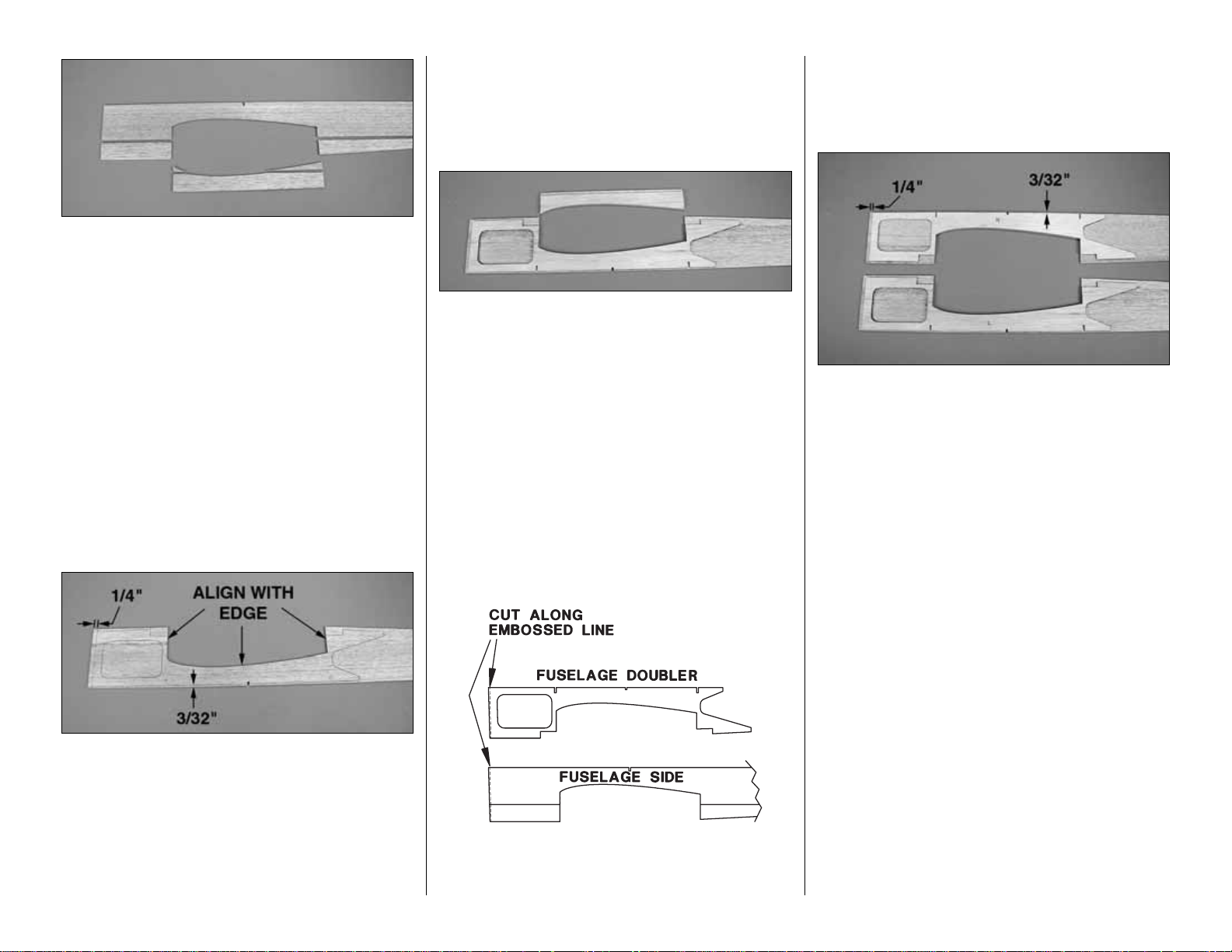
❏ 5. Position one of the sides on your building board
as shown in the photo. Position the die-cut 1/8"
[3.2mm] ply fuselage side doubler on the fuselage
side. Align the doubler with the wing saddle and
trace the outline of the doubler onto the fuselage
side with a ball point pen.
Note: It is impor tant that the doubler be accurately
positioned on the fuselage side. Check that the
fuselage side extends 1/4" [6.4mm] beyond the
doubler at the front end of the assembly. Also check
that the fuselage side extends 3/32" [2.4mm]
beyond the doubler along the edge of the assembly
as shown in the photo.
❏ 6. Glue the doubler to the fuselage side using
aliphatic resin glue or epoxy, aligning it accurately in
position. Do not use CA as it will not allow you to
reposition the parts. Use weights to hold the parts
together until the glue dries, making sure the parts
remain accurately positioned.
❏ 7. When the glue has dr ied, remove the side from
the building board. Label this side “L”.
❏ 8. Glue the belly pan doubler to the belly pan
side.Align the doubler with the wing saddle and with
the ends. The belly pan side should extend 1/4"
[6.4mm] beyond the doubler along the straight edge.
Label this assembly “L”.
❏9. Locate the remaining fuselage side assembly and
fuselage side doubler .Note that the front edge of these
parts have an embossed cut line that is about 3/32"
[2.4mm] from the edge. Use a straight edge and your
knife with a sharp #11 blade to cut and remove the
material along the embossed line.This will establish the
proper right thrust for the engine.
❏ 10. Position this side on your building board as
shown in the photo. BE SURE IT IS POSITIONED
AS SHOWN (unless you want two left sides)!
Position the die-cut 1/8" [3.2mm] ply fuselage side
doubler on the fuselage side. Align the doubler as
you did in steps 5 and 6 and glue it in position with
aliphatic resin or epoxy. Use weights to hold the
parts together until the glue dries, making sure the
parts remain accurately positioned.
Note: It is impor tant that the doubler be accurately
positioned on the fuselage side. Check that the
fuselage side extends 1/4" [6.4mm] beyond the
doubler at the front end of the assembly. Also check
that the fuselage side extends 3/32" [2.4mm]
beyond the doubler along the edge of the assembly
as shown in the photo.
❏11.When the glue has dried, remove the side from
the building board. Label this side “R”.
❏ 12. Glue the belly pan doubler to the belly pan
side.Align the doubler with the wing saddle and with
the ends. The belly pan side should extend 1/4"
[6.4mm] beyond the doubler along the straight edge.
Label this assembly “R”.
Caution: Be sure you are building a right side, not
another left.
-15-
Page 16
FRAME THE FUSELAGE
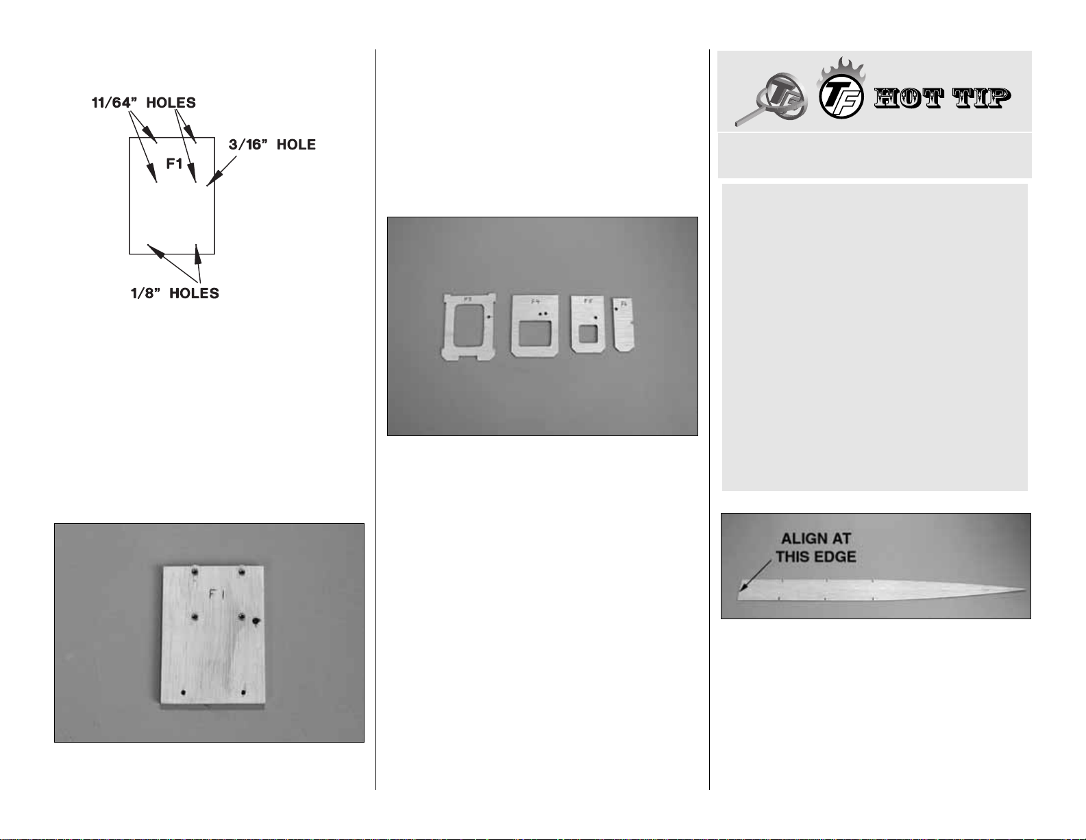
❏1.Locate both die-cut 1/8" [3mm] ply F1 firewalls.
Glue them together using 6-minute epoxy.
Note: Make sure the pin point punch marks are
facing out on one side.Label this side F1.
❏ 2. When the epoxy has cured drill 1/8" [3.2mm]
and 11/64" [4.4mm] holes where shown in the sketch
above. The 3/16" [4.8mm] hole is for the throttle
pushrod for an OS .46 FX.
❏ 3. Install four 6-32 blind nuts in the 11/64" [4.4mm]
holes. Put some epoxy on the blind nuts as you install
them to hold them in place. Be careful not to get any
epoxy in the threaded holes in the blind nuts.
Note:The blind nuts are installed on the aft side of F1.
❏ 4. Referring to the former drawings on the
fuselage plan, drill 3/16" [4.8mm] holes for the
pushrods in formers F2, F3, F4, F5 and F6 at the pin
point punch marks. Label the front of each former.
❏ 5.Refer to the “pushrod exit locations”drawing on
the plan and the HOT TIP below.Drill 3/16" [4.8mm]
holes in the fuselage sides for the pushrods.The left
side has one hole for the rudder pushrod. The right
side has one hole for the elevator pushrod.
Note: The drawing shows where the holes should
enter and exit the fuselage sides on the inside and
outside.This allows you to judge the angle at which
the holes should be drilled.
❏ 6. Locate the die-cut 3/32" [2.4mm] balsa left and
right fuselage top deck parts. Use your bar sander to
sand the edges flat and straight where the parts join.
Edge glue the left and right fuselage top deck parts
together using either thin CA or aliphatic resin.Align the
parts even at the front edges.Use your bar sander with
150-grit sandpaper to sand the assembled fuselage top
deck flat and smooth.
Note: The front edge is cut at a 2 degree angle to
establish the engine right thrust angle.
A. Mark the fuselage side with pins where the
hole enters and exits the fuselage side.
B. Start by drilling a 3/16" [4.8mm] hole at the
exit point on the outside of the fuselage side.
C.Turn the side over and use a rotar y tool with a
cutoff wheel to cut a trough in the interior of the
fuselage side.The trough should extend from the
pin mark at the entry point to the hole you drilled
at the exit. MAKE SURE you are cutting the
trough on the inside of the fuselage side.
D. Dress the angled hole up by using the 3/16"
[4.8mm] drill at an angle and sliding it in and out
of the hole to shave the hole clean. Any
imperfections at the exit can be filled and sanded
after the pushrod is installed.
HOW TO DRILL ANGLED HOLES
-16-
Page 17
❏ 7. Place the fuselage top deck over the top view of
the fuselage plan.Align the cutouts in the top deck with
formers F2, F3TC and F3. Mark the location of former
F1TR and all of the formers aft of F3.T ransf er the marks
for F4, F5 and F6 to the bottom of the top deck.
❏ 8. Place the right fuselage side over the side view
of the fuselage plan. Align the fuselage side with the
wing saddle.Mark the location of formers F4, F5 and
F6 at the lower edge on the inside of the fuselage
side. Align the left fuselage side with the r ight side
and transfer these marks to the inside of the left
fuselage side.
❏9.Without using any glue, assemble the fuselage top
deck, left and right fuselage sides, F2 and F3. Use
rubber bands to hold the assembly together. Align F2
even with the front of the wing saddle cutout and align
F3 even with the rear of the wing saddle cutout. Be
certain that the forward (marked) sides of F2 and F3 are
facing the front of the fuselage.
IMPORTANT:Check that the front edge of the top deck
is exactly aligned with the front edge of the ply fuselage
doublers.View the fuselage assembly from the top and
insure that the firewall will have RIGHT thrust.
❏ 10. Cover your building board with plan protector
or wax paper. Place the fuselage assembly upside
down on the building board. With the assembly
properly aligned, glue F2 to the top deck and
fuselage sides with thin CA. Be sure that the top
deck is firmly seated against the ply fuse doublers
and that F2 is aligned with the wing saddle cutout.
Squeeze the fuselage sides together against F2 until
the CA cures.
❏ 11. Glue F3 to the top deck and fuselage sides with
thin CA. Be sure that the top deck is firmly seated
against the ply fuse doublers and that F3 is aligned with
the wing saddle cutout. Squeeze the fuselage sides
together against F3 until the CA cures.
❏ 12. Glue the top deck to the fuselage sides
between F2 and F3 with thin CA. Be sure the top
deck is firmly seated against the ply fuse doublers.
❏ 13. Glue the firewall F1 in place to the front of the
fuselage using 30 minute epoxy.Y ou will need to cut two
notches in the top deck to clear the 6-32 blind nuts.
Align F1 with the top of the top deck. F1 will extend
below the bottom of the fuselage by about 3/32"
[2.4mm].Check that the sides and top deck are square.
❏ 14. Reinforce the joint between F1 and the
fuselage sides and top deck with some balsa
triangular sticks cut from a 1/4" x 1/4" tri x 30" [6.4 x
6.4 x 762mm] stick. Glue in place with epoxy. Do not
let any epoxy get into the blind nuts.
Hint: Put some vaseline on the two blind nuts near
the top deck.
-17-
Page 18

❏ 15. Glue the top deck to the fuselage sides
between F1 and F2 with thin CA.
❏ 16. Fit former F4 into position. Note the curve of
the sides. Then, remove F4 and sand the edges of
F4 to match the curve. Glue F4 to the top deck and
fuselage sides with thin CA. Be sure that the top
deck is flush with the top edge of the fuselage sides.
Align F4 with the marks you made earlier on the
bottom of the top deck and on the fuselage sides.
Squeeze the fuselage sides together against F4 until
the CA cures.
Note: Be certain that the forward (marked) side of
F4 is facing the front of the fuselage.
❏ 17. Glue the top deck to the fuselage sides
between F3 and F4.
❏18.In similar fashion, glue F5 and F6 into position.
❏19.Glue the tail end of the fuselage sides together
where they meet.T rim the top deck slightly if needed.
❏ 20.Locate two die-cut 1/8" [3.2mm] ply 1" x 2-7/8"
[25.4 x 73mm] fuse hold down blocks. Glue these
together with medium CA to form a 1/4" [6.4mm]
thick block.Using 30-minute epoxy, glue this block to
the front of F2, between the fuselage sides.Tr im the
block to fit as needed. Make sure the block fits into
the cutout in the fuselage doublers.
❏ 21. Locate two more fuse hold down blocks and
glue them together.Using 30-minute epoxy, glue this
block to the rear of F3, between the fuselage sides.
Make sure the block fits into the cutout in the
fuselage doublers.
❏ 22. Locate two 1/4" x 1/4" x 36" [6.4 x 6.4 x
914mm] triangular balsa sticks.Trim them to fit along
the bottom of the fuselage sides between F3 and the
rear end of the fuselage. Glue them into position.
❏23.Sand the top of the fuselage lightly to remove any
glue bumps. Sand the bottom of the fuselage flat and
level.Sand the front and rear ends flat and smooth.
INSTALL THE PUSHRODS AND SERVOS
The elevator servo is installed on the left side of the
fuselage and the pushrod for that servo exits from the
right side of the fuselage.
❏ 1. Locate the two 36" [914mm] plastic pushrod
tubes. Cut one of these tubes to a length of 16"
[406mm]. Cut the remaining tube to a length of 21"
[533mm]. Save the remainder of the tubes for use
later. Use some 150-grit sandpaper to lightly
roughen the outside of the tubes.
❏2. Install the 16" [406mm] tube in the proper holes in
the fuselage side and formers for the elevator pushrod,
inserting it from the rear. The tube should extend 1/8"
[3.2mm] beyond F3.Install the 21" [533mm] tube in the
proper holes for the rudder pushrod. This tube should
extend 4-1/2" [107mm] beyond F3. Glue the tubes in
position with some medium CA at each former and the
fuselage sides.
-18-
Page 19

❏ 3. Use a razor saw to trim the pushrods flush with
the fuselage sides. Fill any irregularities with
balsa filler.
IMPORTANT NOTES ABOUT SERVOS
The following steps show the installation of three full
size servos in the fuselage;one each for the elev ator ,
rudder and throttle. The wing also has two aileron
servos and one flap servo, plus a retract servo if you
are installing retractable landing gear. If you have a
computer radio and want to use some of its mixing
capabilities, there is adequate room in the fuselage
for a second elevator servo.The wing also has room
for a second flap servo. If you do install additional
servos it is recommended that you use mini servos
for their smaller size and lighter weight.
You MUST install your servos so that the servo arm
is located in the position shown on the plan. Install
the servo rails so that the servos you use will be in
the proper location.
Servo output torque is a consideration when you
select the servos that you will use. Standard size
servos have adequate torque for any control
function. If you are using mini servos you should use
two servos for the elevators that have at least 35 oz
in of torque each. The rudder servo should have at
least 42 oz in of torque. This will insure that the
control surfaces can reach full deflection at
maximum flying airspeeds.
We recommend Z-bends be used for the pushrods
where they connect to the servo arms.This results in
the most compact installation possible and will
reduce the possibility of a pushrod contacting
something close to it. As an alternative you can use
an L-bend with one of the supplied nylon Faslink
keepers. For making Z-bends we highly recommend
the Precision Z-bend Pliers from Great Planes
(GPMR8025).This tool makes very precise Z-bends
in tight areas and is one of those tools you wonder
how you ever got along without.
❏ 4. Locate a .074 x 36" [1.6 x 914mm] pushrod
wire. Bend a Z-bend (or L-bend) in the unthreaded
end of the wire. Make this bend close to the end of
the wire. Install a servo arm on the Z-bend.You may
need to drill the servo arm with a 5/64" [2mm] drill.
Insert this wire into the elevator pushrod tube where
the tube exits F3. DO NOT cut off the excess wire
where it exits the rear of the fuselage.This pushrod
wire will be used as locating jig for the elev ator servo .
❏ 5. From the 1/4" x 3/8" x 36" [6.4 x 9.5 x 914mm]
basswood stick, cut two servo mounting rails to a
length of 2-5/8" [66.7mm]. These rails should be a
tight fit against the fuselage sides so that they can
hold the servo in position during the following steps.
❏ 6. Install one of the ser vo rails against F3. Place
the elevator servo in position on the rail and install
the second rail at the forward end of the servo .Install
the servo arm, with the wire attached, on the servo.
Refer to the note and photo below if you are using
full size servos. DO NOT glue the rails at this time.
Note: If you are using a full size servo, you will need
to cut a hole in the fuselage deck for the servo bef ore
you can install the servo arm. Mark the deck from
inside the fuselage where you need to cut the hole.
Then, remove the servo. Transfer the location of the
hole to the top of the deck by pushing a pin through
the deck at the corners of the hole. Cut out the hole
from the top of the deck.
-19-
Page 20

❏ 7. Position the servo and rails so that the pushrod
wire lines up properly with the pushrod tube. Tack
glue the rails to the fuselage sides. After the CA has
cured, mark the location of the servo mounting
holes. Then, remove the servo and pushrod wire.
Securely glue the rails to the fuselage sides and the
face of F3 with epoxy.
❏ 8. Drill pilot holes for the servo screws and mount
the servo to the rails with the screws, grommets and
eyelets that came with the servo. Remove the servo
and harden the mounting holes with a drop of thin
CA. After the CA has cured, remount the servo to
the rails.
❏ 9. Cut the
spacer bar
off both engine mount
halves and trim off any
flashing
so they fit together.
Temporarily mount the engine mount to F1 using four
6-32 x 3/4" [19.1mm] socket head cap screws, #6
lock washers and #6 flat washers.Place your engine
on the mount, adjusting it for the width of the engine.
Mark the location of the hole for the throttle pushrod.
If you are using an O.S ..46 FX the location is already
marked. Remove the engine but leave the engine
mount in place.
Note:To allow as much room as possible for the fuel
tank, the throttle pushrod should be placed as close
to the fuselage side as possible. See the photo at
step 10.
❏ 10. Drill a 3/16" [4.8mm] hole for the throttle
pushrod at the location you marked.Using a piece of
leftover plastic pushrod tube, install the throttle
pushrod tube in the hole you just drilled in F1 and
into the hole in F2. Trim the tube to length so that it
extends about 1" [25.4mm] beyond F1. Remove the
tube and roughen the ends where it will be glued in
place later.Reinstall the tube.
❏11.Note the position of the throttle servo on the plan.
You will need to cut a hole in the deck for the servo. If
you are using a full size servo, this hole must be close
to the centerline of the model. A mini servo can be
placed close to the side of the fuselage, allowing room
for the switch mount on the other side .Cut a hole for the
servo you will be using, using the plan as a reference.
The photo shows a full size servo.
❏ 12. From the 1/8" x 1/4" x 24" [3.2 x 6.4 x 610mm]
basswood stick, cut two servo mounting rails to a
length of 2-5/8" [66.7mm]. Glue these rails to the top
deck on the inside of the fuselage.Install the throttle
servo, drill pilot holes for the mounting screws and
install the screws, grommets and eyelets that came
with the servo. Remove the servo, harden the
mounting holes with a drop of thin CA and remount
the servo when the CA has cured.
❏ 13.Turn the fuselage over and hold former F2T in
position. Make sure the throttle servo will clear the
sheeting that will be glued to F2T.
Note: You may need to trim some of the 3/16"
[4.8mm] sq. stringer that will be glued to the notch
in F2T.
-20-
Page 21

❏ 14. Install a Screw-Lock connector, nylon
retainer and 4-40 x 1/8" [3.2mm] socket head cap
screw on the outside hole of the servo arm. Install
this arm on the throttle servo.Install a .074 x 12" [1.6
x 305mm] throttle pushrod wire into the throttle
pushrod tube. If needed, adjust the location of the
hole in F2 so that the pushrod lines up with the
screw-lock connector.
Note:You may need to put a small bend in the wire
as shown in the photo. Note also that there will be
minimal clearance between the pushrod linkage and
the wing when it is installed. It may be necessary to
trim a small hole in the wing to clear the linkage.
❏ 15. Note the position of the rudder ser vo on the
plan. It is mounted in the same manner as the
throttle servo.You will need to cut a hole in the deck
for the servo. This hole must be close to the
centerline of the model for either a full size or mini
servo. Cut a hole for the servo you will be using,
using the plan as a reference.
❏ 16. From the 1/8" x 1/4" x 24" [3.2 x 6.4 x 610mm]
basswood stick, cut FOUR servo mounting rails to a
length of 2-5/8" [66.7mm]. Glue two of these rails to
the top deck on the inside of the fuselage. Glue a
second set of rails on top of these rails. This will
space the rudder servo 1/8" [3.2mm] further from the
deck than the throttle servo.Install the rudder ser vo,
drill pilot holes for the mounting screws and install
the screws, grommets and eyelets that came with
the servo. Remove the servo, harden the mounting
holes with a drop of thin CA and remount the servo
when the CA has cured.
❏ 17. Locate the die-cut 1/8" [3.2mm] ply rudder
pushrod brace. Carefully drill a 3/16" [4.8mm] hole in
one end of this brace at the pin point punch mark.Slide
the brace onto the rudder pushrod tube but do not glue
it into place until after the receiver is installed.
❏ 18. Locate the 36" [914mm] wire pushrod, with a
Z-bend in the end, that you used earlier for the
elevator servo installation. Temporarily install the
wire pushrod in the rudder pushrod tube and install
the rudder servo arm on the wire pushrod. Install the
servo arm on the rudder ser vo. Note the location of
the ply rudder pushrod brace.
❏ 19. Remove all of the pushrods.Leave the engine
mount in place.
INST ALL THE RECEIVER
The photos that follow show the installation of the large
Futaba 7-channel FM receiver .There are several other
7, 8 and 9 channel receivers that are smaller.
❏ 1. Using the plan as a guide, cut a hole in the top
deck for the receiver. Make sure the hole is large
enough for the 1/4" [6.4mm] foam that the receiver
will be wrapped in. The receiver should fit firmly in
this hole.
Note:A slot has been cut beside the servos to allow
the servo wires to be neatly routed to the receiver.
Note also the routing of the receiver antenna.
❏2.T urn the fuselage over. Note also how the servo
wires have been routed and that tie wraps are used
to keep the installation neat.The tie wraps are short
lengths of fuel line.
Caution: Once the top of the fuselage has been
sheeted, be careful not to push the receiver firmly into
its cutout.This could cause the receiver to contact the
top sheeting and cause it to split the sheeting.
-21-
Page 22

FINISH THE FUSELAGE
❏
1. Glue the die-cut 1/8" [3.2mm] ply former F3T
into place on the top deck using thin CA. Make sure
that it is perpendicular to the top deck and that it is
centered between the sides, directly on top of F3.
❏ 2. Glue die-cut 1/8" [3.2mm] ply formers F3TR,
F4T, F4TR, F5, F5TR and F6 into position using the
marks you made earlier. Make sure the formers are
perpendicular to the top deck and are centered
between the sides.
❏ 3. Glue a 3/16" x 3/16" x 24" [4.8 x 4.8 x 610mm]
balsa stick from F3T to F5TR. As you glue the stick
to each former make sure the former is
perpendicular to the top deck. Trim the stick even
with F3T and F5TR.
❏ 4. Glue two 1/8" x 1/8" x 24" [3.2 x 3.2 x 610mm]
balsa sticks from F3T and F6T along the top of the
top deck.Trim the sticks even with F3T and F6T.
❏ 5. Use a bar sander with 150-grit sandpaper to
blend the sticks with the shape of the formers.
❏ 6. Glue die-cut 1/8" [3.2mm] ply formers F1T,
F1TR, F2T, F3TC and F3TF in place to the top deck.
Make sure the formers are perpendicular to the top
deck and are centered between the sides.
❏ 7. There are three other formers that are supplied
and are shown in the next photo. These are F2TX and
two F3TX.These formers are shown on the side view of
the fuselage plan. The location of these formers
depends on the location of your servos and receiver.
They are used to prev ent the top sheeting from sagging
between the other formers. Glue F2TX and both F3TX
formers in place as desired.
❏ 8. Glue a 3/16" x 3/16" x 24" [4.8 x 4.8 x 610mm]
balsa stick from F1T to F3TF.As you glue the stick to
each former make sure the former is perpendicular
to the top deck. Trim the stick even with F1T. Use
your bar sander to blend the stick with the shape of
the formers.
Note:If you installed full size servos you will need to
trim the stick where it crosses the servos.
❏ 9. Mount your switch to the side of the fuselage.
We used a Great Planes Switch/Charge Mount
(GPMM1000).You will need to cut a hole in the top
deck for the s witch.We installed the mount on the left
side of the fuselage as it is easier for a right handed
person to reach it.You may want to mount it on the
left side to keep it away from the engine exhaust.
Make sure the mount and switch will clear the wing
when it is mounted to the fuselage.
-22-
Page 23

❏ 10. Locate the four 3/32" x 3" x 24" [2.4 x 76 x
610mm] balsa sheets. Set the two softest sheets
aside for use later. Use the remaining two to sheet
the front of the fuselage in the following steps.
❏ 11. Cut both sheets to a length of 15-1/2"
[394mm].Sand an angle along one long edge of both
sheets as shown in the sketch. Fit a piece of
sheeting to the area to be covered between F1T and
F3TF on the left side of the fuselage. See the photo
at step 12 below.
Note: There will be a 1/32" [0.8mm] lip where the
fuselage side overhangs the top sheeting. This will
be sanded away later.
❏ 12. Using thin CA, glue the angled edge of the
sheeting to the top of the fuselage side and the
bottom of the formers.
❏ 13. Moisten the outside of the sheeting so that it
will bend easier. Most modelers use a mixture of
water and ammonia. We prefer rubbing alcohol with
a spray nozzle attached to the bottle.It soaks into the
balsa easily and dries very fast.
❏ 14. Bend the sheeting against the formers, one at
a time.While holding it in place, glue it to the former
and stringer with thin CA. Do not become concerned
if the sheeting splits at one end as ours did.Glue the
split together and then glue it to the formers. It can
be filled and sanded later.
❏ 15. Fit the second piece of sheeting to the other
side of the fuselage. Be sure the angled edge is
resting properly on the top of the fuselage side. Cut
the sheeting 1/16" [1.6mm] oversize.
❏ 16. Carefully hold the sheeting in position along
the top edge of the fuselage and then roll it along the
former until it meets the sheeting on the other side.
Note how much must be sanded off to get it to fit
properly. Remove the sheeting and sand as needed.
Do not sand off too much. Refit the sheeting and
check it again. Go from former to former and sand a
little off each time. You will quickly have a perfect
fitting piece.
❏ 17. Glue this piece of sheeting in place in the same
manner as you did the first piece. It is easier to use
medium CA on the formers and thin CA on the stringer.
The rear turtle deck of the fuselage is sheeted in
exactly the same manner as the top front.Fitting the
balsa sheeting is a bit more difficult as the slope and
curvature are greater.
C.In the same manner, mark the sheeting at F1T.
D. The sheeting is straight from F3T to F2T and
then slowly slopes to F1T. Mark the sheeting
where it crosses F2T.T r ansf er the mark at F3T to
F2T. Our F3T mark showed the sheeting needs
to be 1-15/16" [49.2mm] wide at F3T. It should
also be 1-15/16" [49.2mm] wide at F2T as well.
E. Cut the sheeting in a straight line between the
marks from F3T to F2T. Cut the sheeting at an
angle between the marks at F2T to F1T.
A. Mark the center of the 3/16" [4.8mm] stringer
onto F3T.
B.At formers F2T and F3T, hold the angled edge
of the sheeting in place along the top edge of the
fuselage side. Carefully roll the sheeting along
the former until it is resting on the stringer. Mark
the location of the center of the stringer on the
sheeting at F3T.
HOW TO FIT SHEETING
-23-
Page 24

❏ 18. Locate the two soft 3/32" x 3" x 24" [2.4 x 76 x
610mm] balsa sheets you set aside in step 10. Cut
both sheets to a length of 14" [356mm].Fit a piece of
sheeting to the area to be covered between F3T and
F6T on the left side of the fuselage. Glue the sheet
into position with thin CA.
Note: There is a small area of the sheeting at the top
near F3T that needs to be filled in.Use a corner of the
piece you just cut off and glue it to the sheeting.
❏ 19. Fit the second piece of sheeting to the other
side of the fuselage. Glue it into position with
medium and thin CA.
❏ 20. Trim and sand all of the sheeting flush with
F1T, F3T and F6T.
Note: A 1/4" [6.4mm] notch will be cut in the top of
the sheeting between F5TR and F6T when the
vertical fin is installed.
This completes the assembly of the fuselage. The
bottom sheeting will be added when the wing is
mounted to the fuselage.
BUILD THE WING
BUILD THE RIGHT PANEL
❏ 1. Remove all of the ribs from the die-cut 1/16"
[1.6mm] balsa sheets. When doing so, do not
remove any of the lightening hole cutouts in W2, W3
and W4. Remove the spar webs from the die-cut
3/32" [2.4mm] balsa sheet.Remove the TE spar/jigs
from the die-cut 1/16" [1.6mm] balsa sheet. Be very
careful not to let any of the jig tabs split off of the jig.
If any do, glue them back on. Remove all of the ply
wing parts from their die-cut sheets.
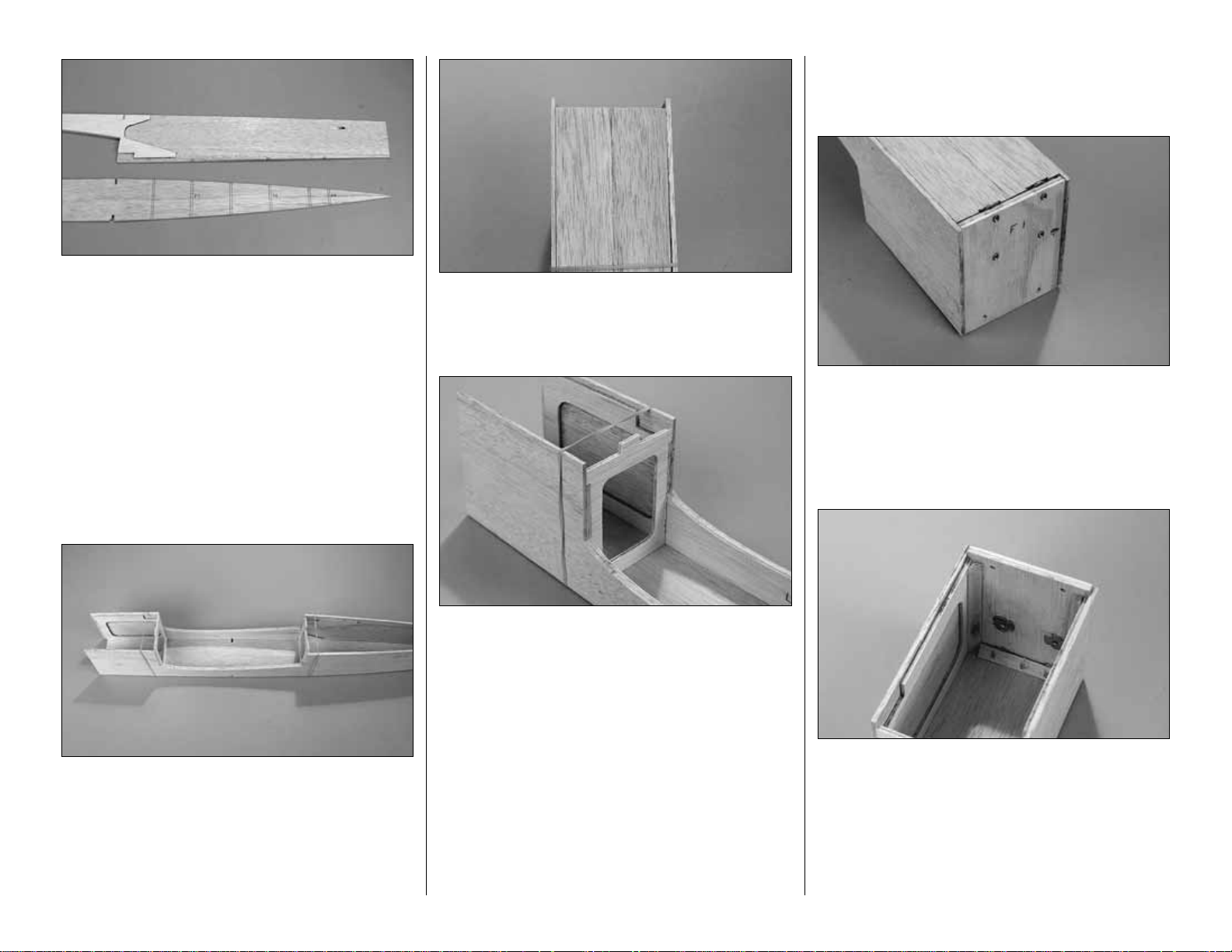
❏2.Prepare four leading edge skins as shown in the
sketch above. Locate five pieces of 1/16" x 3" x 24"
[1.6 x 76 x 610mm] sheeting. From one sheet cut
four strips that are 1/2" [12.7mm] wide. Glue a 1/2"
[12.7mm] strip to each of the other four pieces of
sheeting, making sheets that are 3-1/2" [89mm]
wide. Sand each sheet flat and smooth on one side
with your bar sander and 150-grit sandpaper. Sand
any glue bumps from the other side of each sheet.
Caution: Avoid over sanding the sheets, making
them too thin.
Remember:
“R-steps” are for retracts only;
“F-steps” are for fixed gear;
Note: Use a colored marker to highlight the
steps for your landing gear option.
Retracts go to step R9.
Note: Portions of this manual that apply only to
fixed landing gear begin with an “F”. For
example: Step F3 is for fixed gear only. Steps
that apply to retract landing gear are shaded
and begin with an “R”, such as step R6. It is
assumed that most modelers will be installing
fixed tail dragger landing gear (with a tail wheel),
so just skip the shaded steps that begin with an
R. If you are building your model for retracts,
make sure you read the steps that are shaded
and skip steps that begin with an F.
-24-
Page 25

❏ F3. If you are installing fixed gear on your model,
prepare both W2 ribs as shown in the above sketch.
Glue the lightening hole forward of the spars back into
the rib.Remove the two pieces from the lightening hole
aft of the spars.
❏ F4. Glue a die-cut 1/8" [3.2mm] ply W2TD
doubler to each W2 with 6-minute epoxy.Make sure
to make a left and right assembly. Cut and remove
the balsa from the rib where there is a notch in
W2TD for the landing gear rail.
Important: Notice the orientation of the TE notch in
relation to the W2TD notch.
❏ F5. In the same manner, prepare the W3 and W4
ribs. Continue with step 9.
❏ 9. Cut the right wing plan along the dashed line
and tape it to your building board.Cover the plan with
Plan Protector or wax paper.
❏❏10. Locate a die-cut 3/32" [2.4mm] balsa spar
web.Working from the narrow end of the web, slide ribs
W2 thru W9 into position on the web. Twist each rib so
that it seats properly in the web. Be sure that the ply
doublers on W2, W3 and W4 are on the correct side.
Also be sure that the notch for the TE web/jig is facing
down when each rib is twisted into position.
❏❏11.Position a 1/8" x 1/4" x 24" [3.2 x 6.4 x 610mm]
basswood bottom spar over its location on the plan,
aligning the spar so that a little overhangs each end.Pin
the spar to the plan at the ends. Don’t stick your pins
through the spar as it will split the spar. Instead, stick
them into your building board over the spar in a
❏ R8. In the same manner, prepare both W4 ribs.
Remove the lightening holes from both W2 ribs.
❏ R7. Glue a die-cut 1/8" [3.2mm] ply W3R
doubler to each W3 using 6-minute epoxy. Make
sure to make a left and right assembly. Cut and
remove the balsa from the rib where the notches
are in W3R for the landing gear rails.
Important: Notice the orientation of the TE notch
in relation to the W3R notches.
❏ R6. If you are installing retracts (retractable
landing gear) on your model, prepare both W3
ribs as shown in the above sketch. Glue the
lightening hole forward of the spars into the rib.
Remove the two pieces from the lightening hole
aft of the spars.
-25-
Page 26

crisscross
fashion. Place an additional pair of pins
beside the spar between ribs W5 and W6. Do not
crisscross these as it would interfere with the spar web .
Stick them into your building board vertically so that
they keep the spar in position.
❏❏12. Position the spar web, with ribs, onto the
bottom spar.Align the ribs over their locations on the
plan. Install W1 and W10 on the spar and spar web.
Make sure each rib is seated onto the bottom spar
and that the spar web is against the forward part of
the cutout in each rib. DO NOT apply glue until
instructed to do so.
Note: Do not be concerned if the ribs do not exactly
align spanwise with the plans. Paper plans can
expand and contract as much as 1/8" [3.2mm] due
to moisture.
❏❏13. Position the TE spar/jig flat on the building
board, under the TE notches in the ribs.The jig tabs
must be facing the bottom spar and the widest
part of the TE spar/jig must be at W1.
❏❏14.Carefully rotate the TE spar/jig so that the jig
tabs are facing up, while also sliding each rib into the
slot in the TE spar/jig.Make sure that each rib is seated
in the notch in the TE spar/jig and that the TE spar/jig is
seated in the notches in the ribs. Pin the TE spar/jig in
location over the plan.DO NOT glue yet.
❏❏15.Put the 1/8" x 1/4" x 24" [3.2 x 6.4 x 610mm]
basswood top spar into position on the spar web,
seating it in each rib. DO NOT glue yet.
❏❏16. Time to get the thin CA. Starting with W3
and working towards W10, glue each rib to the
bottom spar and the spar web.While doing so, press
the rib and spar web firmly onto the bottom spar until
the CA cures. Make sure the rib is firmly seated
against the front face of the spar web and also that
the TE spar/jig and rib remain in place.
Important: For maximum wing strength it is
essential that the joint between the spar web and
the top and bottom spars, as well as the joint
between the spar web and each rib, be securely
glued with no gaps. When you remove the wing
panel from the building board in a later step, be sure
to touch up any joints that need additional glue.
❏❏17. Tack glue W1 and W2 in place to the spar
web.There is a 1/16" [1.6mm] gap between the spar
web and the top and bottom spars. Do not get any
excess glue into this gap as the 1/16" [1.6mm] ply
spar joiners fit into the gap.
❏❏18. Remove the top basswood spar. Spread a
bead of medium CA along the top of the spar web
between W2 to W10 and on each rib where the top
spar will contact them. Re-install the top spar and
hold it firmly in place against the spar web until the
CA cures.
❏❏19.Glue each rib to the TE spar/jig with thin CA.
Make sure each rib is properly seated in the TE
spar/jig.The top of each rib should be even with the
top of the TE spar.
Note: Use the CA sparingly. If you apply an
excessive amount of CA it will be difficult to remove
the bottom of the jig under the ribs.Use the included
CA applicator tip.
❏❏20. Glue the 1/8" x 3/16" x 24" [3.2 x 4.8 x
610mm] balsa trailing edg e to the rear of the ribs
with thin CA. The top of the trailing edge should be
even with the tops of the ribs.
❏❏21. Glue the tapered 5/32" to 1/2" x 1/4" x 24"
[4 to 12.7 x 6.4 x 610mm] balsa leading edge to the
-26-
Page 27

front of each rib with thin CA. The top of the leading
edge should be even with the tops of the ribs.Use a
straight edge along the sides of W1 and W10 to
insure that they are straight.
Note:You will need to carefully sand the front of W2,
W3 and W4 at an angle to match the sweep of the
LE if those ribs have a ply doubler installed.
❏❏22. Use your bar sander with 150-grit sandpaper
to lightly sand the top of the leading edge to blend it
evenly with the tops of the ribs.
❏❏23. Using medium CA, glue one of the leading
edge skins that you prepared in step 2 into place on
the ribs and the top spar. The skin should extend
forward from the center of the spar. Refer to the
HOT
TIP
that follows.
Note: Make sure you glue the skin in place with the
smooth side facing out. Position the 1/2" [12.7mm]
strip that was glued to the sheeting at the spar.
❏❏24. Remove the wing panel from the building
board. Glue the wing skin to the tapered leading
edge with thin CA. Checking from the bottom of the
wing panel, insure that the leading edge skin is
securely glued to the tops of all the ribs.
❏❏25. Carefully check all of the glue joints
between the spar web, top and bottom spars and the
wing ribs. Fill in any glue joints that don’t look solid
with thin CA.
❏❏26. Trim the leading edge, leading edge
sheeting, spars and trailing edge even with W1 and
W10. Trim the leading edge sheeting even with the
front of the tapered leading edge.
❏❏27. Snap the bottom of the TE spar/jig off even
with the bottom of the ribs. The TE spar/jig has an
embossed cut line where it is to be snapped off.OK,
so you got too much CA on the TE spar/jig when you
glued the ribs in place. Use a razor saw to cut along
the embossed line.
Important:Use caution not to break any of the short
jig tabs off of the top of the TE spar/jig.
❏❏28. Use your sanding bar to sand the bottom of
the tapered leading edge even with the bottom of the
ribs, following the contour of the ribs.Do not change
the shape of the ribs. Also sand the trailing edge, TE
spar/jig and bottom spar even with the ribs.
❏❏29.Turn the wing panel upside down and place
it on your building board. Pin the TE spar/jig to the
board and use weights to hold the front of the wing
panel on the building board.
Retracts go to step R33.
Use the following photo for the next two steps.
❏❏F30. If you are installing fixed landing gear on
your model, glue the 7/16" x 5/8" x 5-5/8" [11.1 x
15.9 x 142.9mm] basswood grooved landing gear
rail into the notches in W2, W3 and W4 using
6-minute epoxy.The groove in the rail should f ace the
bottom surface of the wing. Glue the 7/16" x 5/8" x
7/8" [11.1 x 15.9 x 22.2mm] maple torque block to
the top surface of the rail against W2, as shown on
the plan.
Note: Before gluing the rail in place check the fit of
the rail in the notches.The rail should protrude 1/16"
[1.6mm] from the bottom of the ribs so as to be level
with the 1/16" [1.6mm] balsa sheeting when the
wing is sheeted.
❏❏F31. Mark the bottom of the groove in the
landing gear rail 3/16" [4.8mm] from the edge of W2.
Drill a 5/32" [4mm] hole through the landing gear rail
and the torque block at the mark. As you drill, make
sure you hold your drill at a 90 degree angle to the
landing gear rail.
Note: The hole should go into the middle of
the torque block. Be careful not to drill through the
top skin.
After you remove the wing from the building
board, use thin CA to glue the skin to the tapered
leading edge. Working one section at a time
between two ribs, hold the skin to the tapered
leading edge and wick in some thin CA. Fir mly
hold the skin in place until the CA cures.
It can be difficult to get a tight glue joint between
the leading edge skin and the tapered balsa
leading edge while the wing panel is still on the
building board. Do not apply any CA to the
tapered leading edge until after you remove the
wing from the building board in the next step.
-27-
Page 28

❏❏F32. Chamfer the inside edge of the hole in the
landing gear rail to accommodate the bend of the
landing gear wire.This will allow it to fully
seat
in the
groove.Test fit the 5/32" [4mm] landing gear wire in
the landing gear rail. Make adjustments where
necessary for a good fit. Continue with step 36.
❏❏36. Glue the bottom 1/16" x 1-7/16" x 24" [1.6 x
36.5 x 610mm] balsa trailing edge sheet into place
with medium CA.
❏❏37. Using medium CA or aliphatic resin, glue
one of the leading edge skins that you prepared in
step 2 into place on the ribs and the bottom spar.The
skin should extend forward from the center of the
spar.Refer to the
HOT TIP
that follows.
Note: If you are installing retracts, do not glue the
skin to the rails until later.
Note: Make sure you glue the skin in place with the
smooth side facing out. Position the 1/2" [12.7mm]
strip that was glued to the sheeting at the spar.
Note: If you are installing fixed landing gear, cut the
Fixed Gear Rail Template
from the wing plan and
use it as a guide to cut the sheeting for the landing
gear rail.
❏❏R35. Glue the die-cut 1/16" [1.6mm] balsa
partial rib W1R into position. Make sure that it
is positioned so that the wheel will clear W1R by
1/16" [1.6mm] when it is retracted. Less clearance
will cause the wheel to jam while more clearance
will make the retract servo hard to fit. On our
prototype model W1R is 1-9/16" [39.7mm] from
W1. This is also a good time to dr ill a hole for the
pushrod to the servo in W1R. Ours was 7/8"
[22.2mm] (1-7/8" [47.6mm] left panel) forward of
the spar web and close to the top sheeting.
Note:In the photo, W2 was trimmed slightly to put
the wheel into position.
and the retract mounting rail(s) to fit the retract
unit.The best tool for this is a rotary tool with a 1/2"
[12.7mm] sanding drum. Do not trim W2 for the
wheel.The wheel will be fitted after the sheeting is
installed. Drill pilot holes for the #4 x 3/8" flat head
sheet metal screws. You will note from the photo
that we have marked the position of the retr act unit
on the rails. This will be useful later when the
sheeting is trimmed to fit the retract unit.
Note:This model was specifically designed for the
.40 size retracts from Great Planes (GPMQ2905).
These units are strong, compact and inexpensive .
They are relatively easy to fit and install.
❏❏R34.Fit and temporarily install the right retract
landing gear to the rails.You will need to trim W3
❏❏R33. If you are installing retracts (retractable
landing gear) on your model, cut two 3" [76mm]
rails from the leftover 1/4" x 3/8" [6.4 x 9.5mm]
basswood stick. Glue these rails into the notches
in W3 and W4 using 6-minute epoxy.
-28-
Page 29

❏❏38. Cut, fit and glue cap strips for the bottom
of ribs W4, W5, W8, W9 and W10 from a 1/16" x 1/4"
x 30" [1.6 x 6.4 x 762mm] balsa stick.
❏❏39. Glue die-cut 1/16" [1.6mm] balsaW6D and
W7D into position on ribs W6 and W7.W6D is glued
to the root side of W6 and W7D is glued to the tip
side of W7.
❏❏40.Cut two 2-3/4" [70mm] servo hatch mounting
rails from a leftover 1/8" x 1/4" [3.2 x 6.4mm] bass wood
stick. Glue them to the notches in W6 and W7 with 6minute epoxy. Do not use the two 1/8" x 1/4" x 24" [3.2 x
6.4 x 610mm] basswood spars left for the other
wing panel.
❏❏41.Center the die-cut 1/16" [1.6mm] ply aileron
servo hatch on the servo rails. Make sure the hatch
is centered on W6 and W7 and that the cutout in the
hatch is closest to the tip. Drill 1/16" [1.6mm] holes
through the hatch and servo rails at the six punch
marks. Remove the hatch and enlarge the holes
in
the hatch only
with a 3/32" [2.4mm] drill. Use a
countersink, or a 3/16" [4.8mm] drill, to countersink
the holes in the hatch, for the #2 x 3/8" [9.5mm] flat
head sheet metal screws. Mount the hatch to the
rails with six #2 x 3/8" [9.5mm] screws. Remove the
hatch and harden the holes with a couple of drops of
thin CA. After the CA has cured mount the hatch to
the rails.
❏❏42. Cut, fit and glue cap strips to W6D and W7D
using a 1/16" x 1/4" [1.6 x 6.4mm] balsa stick.Be careful
not to get any glue on the hatch.Fit and glue cap strips
at the front and rear of the hatch as well.
❏❏43. Remove the aileron servo hatch. Remove
the wing panel from the building board. Securely
glue any of the cap strips to the ribs if any require it.
Tr im the sheeting even with W1 and W10.
❏❏44.Turn the wing panel over. Snap the jig tabs
off of the TE spar/jig. Use your sanding bar to sand
the trailing edge and TE spar even with the ribs. Be
careful not to alter the shape of the ribs.
❏❏45. Using the plan as a guide, cut seven TE
hinge blocks for the aileron and flap hinges from a
1/8" x 1/4" x 24" [3.2 x 6.4 x 610mm] balsa stick.
Glue the hinge blocks into place with thin CA.
If some of the glue joints were loose when you
glued the first leading edge skin on, you may
want to use aliphatic resin glue for this skin.Most
aliphatic resin glues can be heat activated after
the glue has dried, allowing a loose skin joint to
be ironed back into place.
-29-
Page 30

❏❏46.Glue the top 1/16" x 1-7/16" x 24" [1.6 x 36.5
x 610mm] balsa trailing edge sheet into place with
medium CA or aliphatic resin glue. Trim the sheet
even with W1 and W10.
❏❏47. Cut, fit and glue cap strips for the top of
ribs W4 thru W10 from 1/16" x 1/4" x 30" [1.6 x 6.4 x
762mm] balsa sticks.
❏ 48. Cut the left wing plan along the dashed line
and tape it to your building board.Cover the plan with
Plan Protector or wax paper.Build the left wing panel
starting with step 10.
That completes the construction of the wing panels.
You can rough sand them now or wait until they are
joined and the center sheeting is installed.
BUILD THE WING TIPS
It is easiest to build the wing tip as a separate
assembly and then glue it to the wing. All of the tip
ribs are slightly oversize in length to allow them to
be blended and rounded at the tip. T5 and T6 are
slightly tall as well.
❏❏1. Locate a die-cut 1/16" [1.6mm] balsa wing
tip core and two each of tip ribs T1 thru T6. Place
the tip core over the plan and mark the location of all
the tip ribs.
Use the following photo for the next four steps.
❏❏2. Use thin CA to glue the parts together.Work
on one side of the tip at a time. Start by gluing T4 in
position, making sure that it is perpendicular to the
wing tip core.
❏❏3. Next, glue T2 in position, making sure T4 is
perpendicular. Refer to the plan to see how angles
are sanded onto T2 where it joins T4.
❏❏4. Glue T1 and T3 into position.
❏❏5. Glue T5 and T6 into position.
❏❏6.Turn the tip over and glue a second set of tip
ribs into position.
❏ 7. Return to step 1 and build a second wing tip.
The wing tips will be glued into place during
final assembly.
BUILD THE AILERONS
❏1. Place the right aileron plan on your building board.
Cover the plan with Plan Protector or wax paper.
Note: All aileron parts are cut from 1/8" x 1/4" x 30"
[3.2 x 6.4 x 762mm] balsa sticks.
❏❏2. Cut the aileron TE and LE from a 1/8" x 1/4"
x 30" [3.2 x 6.4 x 762mm] balsa stick and pin them in
position over the plan.
❏❏3.Cut the aileron ends from the remainder of the
stick and pin them in position.DO NOT glue until later.
-30-
Page 31

❏❏4. Cut the aileron ribs, diagonals and hinge
blocks from a soft 1/8" x 1/4" x 30" [3.2 x 6.4 x
762mm] balsa stick and place them into position.
Glue all of the parts together with thin CA where they
join each other.
❏❏5.After the CA has cured, remove the pins from
the aileron. Use a sanding block with 150-grit
sandpaper to sand the aileron flat.
❏❏6. From a 1/16" x 3" x 24" [1.6 x 76 x 610mm]
balsa sheet cut two pieces to a length of 11"
[279mm]. Use medium CA or aliphatic resin to glue
one piece to the top of the aileron. Align the skin
even with the LE of the aileron.
❏❏7. After the glue dries, remove the aileron from
the building board and trim the sheeting along the TE
and both tips.
❏❏8.Turn the aileron ov er and use a sanding bloc k
to sand the un-sheeted side flat. Use medium CA or
aliphatic resin to glue the second skin to the aileron.
Align the skin even with the LE of the aileron.
❏❏9. After the glue dries, remove the aileron from
the building board and trim the sheeting along the TE
and both tips.
❏❏10. Locate a die-cut 1/16" [1.6mm] ply control
horn mount.Using the plan as a reference, position the
control horn mount on the aileron and mark its location.
Cut along the lines you marked and remove the balsa to
inset the mount. Glue the mount into the aileron.
NOTE:When you build the second aileron, be sure
to make a left and right aileron. The second aileron
will need to have the mount glued to the other side.
❏ 11. Build a second aileron starting at step 2
above.The ailerons are symmetrical so you can build
the second one over the same plan.
BUILD THE FLAPS
❏
1. Place the right flap plan on your building board.
Cover the plan with Plan Protector or wax paper.
Note:All flap parts are cut from 1/8" x 1/4" x 30" [3.2
x 6.4 x 762mm] balsa sticks.
❏❏2. Cut the flap TE and LE from a 1/8" x 1/4" x
30" [3.2 x 6.4 x 762mm] balsa stick and pin them in
position over the plan.
❏❏3.Cut the flap ends from the remainder of the stick
and pin them in position. DO NOT glue until later.
❏❏4.Cut the flap ribs, diagonals and hinge blocks
from a soft 1/8" x 1/4" x 30" [3.2 x 6.4 x 762mm] balsa
stick and place them into position. Glue all of the parts
together with thin CA where they join each other.
❏❏5.After the CA has cured, remove the pins from
the flap.Use a sanding block with 150-g rit sandpaper
to sand the flap flat.
-31-
Page 32

❏❏6. From a 1/16" x 3" x 24" [1.6 x 76 x 610mm]
balsa sheet cut two pieces to a length of 11"
[279mm]. Use medium CA or aliphatic resin to glue
one piece to the top of the flap. Align the skin even
with the LE of the flap.
❏❏7. After the glue dries, remove the flap from the
building board and trim the sheeting along the TE
and both tips.
❏❏8. Turn the flap over and use a sanding block
to sand the un-sheeted side flat. Use medium CA or
aliphatic resin to glue the second skin to the flap.
Align the skin even with the LE of the flap.
❏❏9.After the glue dries, remove the flap from the
building board and trim the sheeting along the TE
and both tips.
❏10. Build a second flap starting at step 2 above.The
flaps are symmetrical so you can build the second one
over the same plan.
❏ 11. Use a file or a rotar y tool with a cut-off wheel
to remove sharp edges or burrs on the ends of the
flap joiner. Position the flap joiner on the top of both
flaps as shown on the plan and in the photo. Mark
the leading edge of the flaps where the
arm
portion
of the joiner will enter each flap. The center of the
hole will be about 3/8" [9.5mm] from the end.
❏ 12. Drill a 1/8" [3.2mm] hole 1-1/4" deep into the
leading edge of both flaps at the mark you made. Be
sure to drill the hole on the centerline of the leading
edge. Cut a groove in the leading edge to
accommodate the flap joiner. If necessary, remove the
joiner and
tweak
it so both flaps are in the same plane.
Hint: Use a 1/8" [3.2mm] brass tube sharpened at
one end to cut the groove.
HINGE THE AILERONS AND FLAPS
Hinge the ailerons and flaps in exactly the same
manner as you did the elevators and rudder.
❏ 1.Use a straightedge to mark the centerline of the
ailerons and flaps as well as the TE of the wing with
a ballpoint pen. Mark the location of the hinge slots
on the ailerons, flaps and wing TE where shown on
the plan.Cut the hinge slots in the ailerons, flaps and
wing TE along the center lines with a #11 blade or
the Great Planes Slot Machine.
❏ 2. Cut twelve hinges to a size of 3/4" x 1" [19 x
25.4mm] from the CA hinge strip. Snip the corners
off so they go into the slots easier.
❏ 3.Test fit the hinges into the slots.If the hinges do
not slide into the slots easily, work your knife blade
back and forth in the slot a few times to provide
more clearance.
❏ 4. Drill a 3/32" [2.4mm] hole, 1/2" [12.7mm] deep
in the center of the hinge slots.Use a rotary tool with
a 3/32" [2.4mm] drill bit or a carbide cutter for the
best results. Reinsert your knife blade to
clean out
the slot after you drill the holes.
❏ 5. Test fit the ailerons and flaps to the wing with
the hinges.If any hinge slots are not wide enough or
are misaligned, make adjustments so the ailerons
and flaps accurately fit the wing.
❏ 6. Bevel the leading edges of the ailerons and
flaps to a “V” as shown on the cross section of the
plan. Use the center line on the leading edges as a
guide.Test fit the ailerons and flaps to the wing.
Note: Make sure you can obtain the control throws
indicated in the back of the manual. If you cannot,
increase the “V” on the leading edges.
DO NOT glue the hinges until the model has
been covered.
JOIN THE P ANELS
❏
1. Locate both die-cut 1/16" [1.6mm] ply spar
joiners.T rial fit them in the right wing panel, cleaning
any excess glue that may be in the way. The joiner
should go all the way to W2.The angled edge points
to the front of the wing. DO NOT apply any glue.
-32-
Page 33

❏ 2. Mark the joiners where they protrude from the
right wing. Remove them and trial fit them in the left
wing panel, making sure that they can be inserted at
least as far as the marks. If they can’t, find out why.
If they are slightly long, trim them as needed. DO
NOT apply any glue.
❏ 3. Now join the right wing panel to the left,
inserting the joiners into the right panel. Place the
joined wing upside down on the building board (this
will give a small amount of dihedral). The wing
panels should fit as in the photo above. You may
need to use a long flat sanding bar to sand the side
of W1 flat. Adjust each panel so they fit together
properly. The photo above shows how ours fit with
NO sanding.
❏ 4. When you are satisfied with the fit, get the 30-
minute epoxy and mix 1/2 oz.[14g]. Liberally coat the
side of both W1 ribs and the basswood spars, balsa
web and ply spar joiners where they join together.
Slide the joiners and wing panels into place. Use a
paper towel and alcohol to clean any epoxy that
seeps out. Place the assembly on your workbench
upside down. Hold the assembly together with pins
and masking tape.
Note: The wing joint depends on three things for its
strength; the epoxy joint between the ply spar joiners
and the basswood spars, the epoxy joint between the
balsa web and the ply joiners and the center sheeting
that will be installed in the following steps.
❏ 5. Use a sheet of 1/16" x 3" x 24" [1.6 x 76 x
610mm] balsa to cut and fit the bottom center
sheeting. Fit the first piece to the trailing edge. Use
a single strip of balsa to sheet from one W3 rib,
across the center W1 ribs to the other W3 rib. Glue
this piece of sheeting in place with medium CA.
❏ 6. Use the remainder of the sheet to fit a piece
between the leading edge sheeting and the piece
you just installed.
The top center section of the wing will be sheeted
after the flap servo is installed.
MOUNT THE SERV OS IN THE WING
❏❏1.Mount an aileron servo to two 5/16" x 3/4" x 7/8"
[7.9 x 19.1 x 22.2mm] servo mount blocks with the
screws, grommets and ey elets included with y our servo .
❏❏2.Mark the edge of the aileron servo hatch rails
on the inside of the hatch. Remove the hatch from
the wing and use 30-minute epoxy to glue the servo
mount blocks, with the servo attached, to the servo
hatch where shown on the plan. Position the servo
within the lines you marked inside the hatch
indicating where the rails are.The servo arm should
be located in the center of the cutout in the hatch.
Note: Roughen the hatch with sandpaper where the
blocks will be glued so the glue will adhere better.
-33-
Page 34

❏❏3. Drill a 1/16" [1.6mm] hole through the servo
hatch into each servo mount block. Countersink the
hole and install a #2 x 3/8" [9.5mm] flat head sheet
metal screw.
❏❏4. Mount the aileron servo hatch back onto the
wing.The wire will be connected after the flap servo
is mounted.
❏❏5. Make an aileron control rod from a nylon
clevis, clevis retainer and .074" x 6" [1.6 x 152mm]
threaded on one end rod.Thread the clevis on about
15 turns.
Note: The photo above shows the control rod after
the Z-bend is made in step 7.
❏❏6.Mount a small nylon control horn to the ply
control horn mount on the aileron with two 2-56 x
1/2" [12.7mm] screws and the nylon backing plate.
Use a 5/64" [2mm] drill for the holes.
❏❏7. Connect the clevis on the control rod to the
control horn and mount the aileron on the wing with
the hinges. With the aileron centered and the servo
arm at 90 degrees to the servo, make a Z-bend in the
control rod where it will connect to the servo arm.
Connect the control rod to the servo arm.
Note: You can also use an L-bend and one of the
supplied Faslink nylon keepers.
❏ 8. Return to step one for the other aileron.
In the following steps you will mount the flap servo.
It is important that the ser vo linkage be mounted in
the exact position shown on the plan as there is v ery
little clearance with the servos and pushrods
mounted in the fuselage. Use the flap servo
mounting template on the plan as a guide in
positioning the servo.
The flap servo should be installed on the left side as
the flap joiner pivot arm is offset to the left.If you are
installing electric power you MUST use a mini-servo
for the flaps as a full size servo would extend into
the battery compar tment in the wing belly pan.
The fuselage bottom sheeting has not yet been
installed. This allows you to mount the wing and
check clearance with the servo and pushrods.
❏ 9. Cut two servo rails to a length of 5-1/8"
[130.2mm] from the leftover 1/4" x 3/8" [6.4 x 9.5mm]
basswood stick. Make a mark at the center of each
rail. Make another mark on the left side of the center
mark where the inside edge of your servo will be.For
our full size servo, the marks are 3/8" [9.5mm] to the
side of the center mark. Position your servo on each
rail and mark the location of the required mounting
holes. Drill 1/16" [1.6mm] holes at these points.
Harden the holes with a drop of thin CA.
Note: Remember, it is important that the flap
linkages be placed in the correct location.
-34-
Page 35

❏ 10. Using the FLAP SERVO MOUNTING
TEMPLATE as a guide, mark the location of the
basswood rails for the flap servo on the top of rib W1
and both W2 ribs.Fit the ser vo rails in the wing.The
rails extend from one W2 rib, across both W1 ribs, to
the other W2 rib.It will be necessary to notch the W1
ribs for the rails. The bottom sheeting must also be
cut to fit the servo as it will extend below the
sheeting. The top of the ser vo arm should be 3/8"
[9.5mm] above the top sheeting.Use the side view of
the fuselage as a guide in positioning the rails.
❏ 11. Make a flap control rod from a nylon clevis,
clevis retainer and .074" x 6" [1.6 x 152mm] wire
threaded on one end. Install your flap ser vo on the
left side of the wing with the screws, grommets and
eyelets supplied with the servo. Install the flap joiner
in the flaps and fit the flaps to the wing. Connect the
joiner to the control rod you just made.With the flaps
centered and the servo arm at 90 degrees to the
servo, make a Z-bend in the control rod where it will
connect to the servo arm. Connect the control rod to
the servo arm. Note that the control rod is installed
into the top of the servo arm.
❏ 12. Position the wing on the fuselage and check
the clearance of the flap servo and linkage with the
other servos and linkages in the fuselage. There
should be adequate clearance with no conflicts
between any of the servos and their linkages. Make
any adjustments needed now while you can still see
the servos and linkages. You may need to shorten
the flap joiner arm.
❏ 13. Install 12" [305mm] servo wire extensions on
each aileron servo.Secure the connection with tape or
heat shrink tubing.Route the servo wires for each servo
through the wing ribs and out the flap servo area.
Note: For a neater installation, use short lengths of
fuel tubing to tie-wrap the servo wires together.
❏ 14. Sand any epoxy that seeped from the joint
between the panels on the top of the wing. Remove
the flap linkage.Sheet the top center section using a
piece of 1/16" x 3" x 24" [1.6 x 76 x 610mm] balsa in
the same manner that you sheeted the bottom
center section, going from one W3 rib across the
center W1 ribs to the other W3 rib. Cut the opening
for the flap servo close to the servo. Otherwise, the
opening will extend beyond the fuselage side.
FINAL CONSTRUCTION
MOUNT THE WING TO THE FUSELAGE
The following steps will be easier to do if you
remove the ailerons and flaps.
❏1.Measure the width of the fuselage at the leading
edge of the wing. It should be close to 3-1/8"
[79.4mm]. Mark the LE and TE of the wing on both
sides of the centerline exactly 1/2 this amount
(1-9/16" [39.7mm]). Do this on the top and bottom of
the wing.
Note: The photos in this section do not show the
flap servo.
❏ 2. Trial fit the wing to the fuselage, centering it
between the marks you just made.The wing should be
slightly shorter than the opening in the fuselage. When
the flaps are hinged to the wing, the flap joiner rod will
be located on the TE of the wing.Slide the wing forward
in the opening and see if there is room for the flap joiner .
You may need to sand the leading edge of the wing flat,
as shown on the plan, to get the proper spacing.
-35-
Page 36

Note: In the following steps you will build the belly
pan for the wing. Once you tack glue the parts into
position you will remove the wing from the fuselage.
If you are not known for your neat gluing technique,
you may want to put some plan protector or wax
paper between the wing and fuselage to prevent
them from being glued together.
❏ 3. With the wing properly positioned, pin the
leading edge of the wing to the fuselage placing the
pins so they will clear the fuselage sides.Use a tape
measure or string to check that the wing is aligned
properly.To use a string, insert a pin in the aft end of
the fuselage on the centerline. Tie a small loop at
one end of a 36" [914mm] length of string and slip it
over the pin. Fold a piece of masking tape over the
other end of the string and draw an arrow on it.Slide
the tape along the string and align the arrow with one
of the wing tips. Now, swing the string over to the
other wing tip.If the arrow does not align with the tip,
adjust the wing and try again. When the wing is
centered and square with the fuselage, pin the
trailing edge into place so that it cannot shift.
❏ 4. Pin die-cut 1/8" [3.2mm] ply former F2BP to F2
with a 1/32" [0.8mm] spacer between them. A piece
of 1/32" [0.8mm] ply or some cardboard from a
cereal box can be used. You may need to trim F2BP
where it fits to the wing.
❏ 5. In the same manner, Pin F3BP to F3.
❏ 6. Fit the left and right belly pan sides that you
made earlier into place. Make any adjustments
needed for a good fit. Make sure the belly pan sides
are centered in the wing saddle opening. Tack glue
both belly pan sides to the wing with medium CA.
❏ 7. Carefully glue the belly pan sides to F2BP
and F3BP.
❏ 8. Fit and glue die-cut 1/8" [3.2mm] ply former
F2BPD in place 1-5/8" [41.3mm] aft of F2BP. Fit and
glue F3BPD in place 1-5/8" [41.3mm] forward of
F3BP. The bottom of both formers should be even
with the bottom of the belly pan sides.
Note: The photos do not show the flap ser vo that has
already been installed. If you installed the servo
correctly, F3BPD should be just aft of the servo.
❏ 9. From leftover 1/4" [6.4mm] balsa triangular
sticks, cut and glue filler strips on the bottom of the
belly pan sides.
❏ 10. Remove the wing from the fuselage. Securely
glue all of the belly pan parts to the wing. Sand the
bottom and both ends of the belly pan flat and smooth.
❏ 11. Locate the six die-cut 1/8" [3.2mm] ply 1" x 3"
[25.4 x 76mm] wing hold down blocks. Using 6minute epoxy, glue them together to form three 1/4"
[6.4mm] thick hold down blocks.
Note:The pin point punch marks should face out on
both sides.
❏12.Using 6-minute epoxy, glue the three wing hold
down blocks into place on the belly pan.The ends of
the wing hold down blocks should be even with
F2BPD and F3BPD and the other ends should
extend 1-1/8" [28.6mm] bey ond F2BP and F3BP.You
will need to trim the 1/4" [6.4mm] tri balsa between
F2BP and F2BPD.
Note: Position the pin point punch marks as shown
in the photo.
-36-
Page 37

❏ 13. Reposition the wing on the fuselage making
sure it fits properly and that the belly pan sides are
even with the fuselage sides. Dr ill a tap hole for the
1/4-20 nylon bolts in the three wing hold down
blocks. Drill the holes at the pin point punch marks.
The holes go through the wing hold down blocks and
also through the fuse hold down blocks under them.
❏ 14. Remove the wing from the fuselage. Drill the
holes in the
wing hold down blocks
ONLY with a 1/4"
[6.4mm] drill bit. Harden and fuel proof the area with
some thin CA.
❏15.Tap the holes in the fuse hold down blocks with a
1/4-20 tap.Harden the tapped holes with a fe w drops of
thin CA.When the CA cures tap the holes again.
❏ 16. Cut the three 1/4 -20 x 2" [51mm] nylon bolts
to a length of 7/8" [22.2mm]. This is necessary to
clear the fuel tank.
❏ 17. From a leftover 1/8" x 1/4" [3.2 x 6.4mm]
basswood stick cut three pieces 1" [25.4mm] long.
Glue these pieces to the ends of the wing hold down
blocks as shown in the photo.
Note: When the wing is mounted there is a 1/8"
[3.2mm] gap between the wing hold down block and
the fuse hold down block. This allows the 1/4-20
wing bolts to flex a bit should you catch a wing tip on
landing. The 1" [25.4mm] sticks stop the wing hold
down blocks from being deformed when the wing
bolts are tightened.
❏ 18. Install the control linkage on the flap servo.
Plug the flap and elevator servos into the receiver,
turn the transmitter on and temporarily plug a battery
into the receiver. Mount the wing to the fuselage and
check the clearance of the flap servo and linkage
with the other servos and linkages in the fuselage.
Operate the flap servo throughout the full range of
motion. If there are any conflicts you may need to
shorten the flap joiner arm slightly.Remove the wing
from the fuselage and unplug the battery and flap
servo.Tur n the transmitter off.
If you are installing an electric motor on the model
for power, you will want to build a battery access
hatch in the belly pan. If you are installing a glow
engine then just skip the steps for the hatch and
glue the bottom sheeting into place.
❏19. Locate the two die-cut 3/32" [2.4mm] balsa belly
pan sheeting parts. Use your bar sander to sand the
edges flat and straight where the parts join. Edge glue
both parts together using either thin CA or aliphatic
resin. Align the parts even at the front edges.Use your
bar sander with 150-grit sandpaper to sand the
assembled belly pan sheeting flat and smooth.
❏ 20. Glue the belly pan sheeting to the bottom of
the belly pan with medium CA. Drill 1/4" [6.4mm]
holes through the sheeting for the wing bolts.
-37-
Page 38

MOUNT THE STAB AND FIN
❏
1. Mount the wing to the fuselage with the wing
bolts. Make any adjustments to be sure the wing
seats properly in the wing saddle.
❏ 2. Measure the TE of the stab to find the exact
center. Draw a line to the LE from this mark,
perpendicular to the TE of the stab.Position the stab
on the stab mount on the fuselage and align it with
the centerline of the fuselage.Pin the rear of the stab
to the fuselage. Use the pin and string technique to
make sure the stab is properly aligned. View the
stab/fuselage from the rear to make sure the stab is
aligned parallel with the wing. If it is not, use a bar
sander to carefully sand the stab mount so that the
stab is parallel to the wing. Mark the stab where it
meets the fuselage sides.
❏ 3. Use 6-minute epoxy to glue the stab to the
fuselage. Use the pin and str ing to double check the
alignment. View the stab/fuselage from the rear and
check the alignment with the wing.
❏ 4. Cut a 1/4" [6.4mm] wide notch in the top of the
fuselage for the leading edge of the vertical fin. Fit
the fin to the fuselage and check its alignment. It
should be perpendicular to the stab and aligned with
the centerline of the fuselage and stab.
❏ 5. Use 6-minute epoxy to glue the fin to the
fuselage.Double check that it is perpendicular to the
stab. Sight from the front and rear of the model and
make sure the fin is aligned along the centerline of
the fuselage.
❏ 6. Cut the 3/4" x 9" [19.1 x 229mm] balsa
triangular stick into two 4-1/2" [114.3mm] pieces. Cut
and sand these pieces to fit them as filler blocks
between the fin and stab.Glue them in position with
medium CA.
❏ 7. Locate the two die-cut 3/32" [2.4mm] balsa
fuselage bottom sheeting parts. Use your bar
sander to sand the edges flat and straight where the
parts join. Edge glue both parts together using either
thin CA or aliphatic resin. Align the parts even at the
front edges.After the glue dries, use your bar sander
with 150-grit sandpaper to sand the assembled
sheeting flat and smooth.
❏ 8. Glue the fuselage bottom sheeting to the
bottom of the fuselage with medium CA.
❏ 9. Remove the wing from the fuselage. Use
leftover balsa to fill the area around the bottom
sheeting and the rear fuselage hold down block.
-38-
Page 39

❏ 10. Glue the wing tips to each end of the wing.
They should be centered on the LE and TE. Glue a
piece of leftover 1/16" balsa on the TE of the tip as
shown on the plan.
MOUNT THE FUEL TANK
❏ 1. Assemble your tank using the instructions that
came with the tank. If your tank has a 90 degree
fitting, use it pointing to the left side of the tank.
❏ 2. Inser t the tank into the tank compartment and
confirm that the tank will fit properly.When the tank
is installed later you will use some 1/4" [6.4mm] foam
rubber on the sides and bottom of the tank to pad it
and hold it in place. Most 10 ounce tanks will fit, but
if yours is a bit too long it is ok to trim former F2 and
the wing leading edge as needed.
❏3. Remove the tank.Cut two hatch mount rails to a
length of 2-5/8" [66.7mm] from leftover 1/4" x 3/8" [6.4
x 9.5mm] basswood. Fit these rails to the front of the
fuse hold down block as sho wn in the photo and on the
plan. Glue the rails into place with 6-minute epoxy.
❏4.Fit the 1/4" x 2-7/8" x 3-5/8" [6.4 x 73 x 92.1mm]
balsa hatch to the tank compartment opening. You
will need to angle the front end to fit the right thrust
of the firewall. Hold the hatch in position and drill a
tap hole for a 10-32 tap through the hatch and the
1/4" x 3/8" [6.4 x 9.5mm] basswood rails under it.
Enlarge the hole
in the hatch only
with a 3/16"
[4.8mm] drill and harden the hole with some thin CA.
Tap the hole in the basswood rails with a 10-32 tap.
Harden the hole with some thin CA and tap the hole
again when the CA has cured.
❏ 5. Cut one of the 1/8" x 1-1/4" [6.4 x 32mm]
dowels in half.Round one end of each dowel. Insert
the rounded end of each dowel in the 1/8" holes in
the firewall (F1). Clean and enlarge the holes as
needed for the dowels to have a loose fit.
❏6. Put a drop of medium CA on the non-rounded end
of each dowel where it will contact the hatch.Do not get
any glue on the dowels where they insert into the
firewall.Place the hatch into position and hold it until the
CA cures. Remove the hatch with the 1/8" [3.2mm]
dowels attached. Reinforce the glue joint as needed to
be secure.
❏ 7. Cut a 10-32 x 2" [51mm] nylon bolt to a length of
1/2" [13mm].
ROUGH SAND THE MODEL
Time to get the long sanding block with 80-grit
sandpaper and start sanding, but there is good
news. This model was designed for a minimum of
sanding. About all that is needed is to round the
leading edge of the wing, round the corners on the
bottom of the fuselage and round the edges of the
tail feathers.Use the cross sections on the plans as
a reference. You may find it easier to use a small
razor plane to knock off the corners first.
After you have finished the rough sanding, put some
150-grit sandpaper on the sanding block and
smooth the model as needed.
INSTALL THE LANDING GEAR
If you are installing retractable landing gear go to
step R7.
Use this photo for the next three steps.
❏❏F1. Install the main landing gear wires in the
wing.The wires have a 90 degree bend on each end.
One end is 1-1/2" [38mm] long and the other end is
1-3/8" [35mm] long. The shorter 1-3/8" [35mm] end
is inserted into the wing.
-39-
Page 40

❏❏F2. Install two nylon landing gear straps on
each wire. Use four #2 x 3/8" [9.5mm] sheet metal
screws to hold the straps in place. Note that the
straps are angled so that the screws will fit on the
rails properly. Harden the holes for the screws with
some thin CA.
❏❏F3.Install your wheels on the main landing gear
wires using two 5/32" [4mm] wheel collars and 6-32
x 1/8" [3.2mm] set screws for each wheel. Tighten
the set screws to mark their location on the wires.
Then, remove the wheel collars and wheels. Grind
flat spots on the wires at the marks. Reinstall the
wheels and collars. Use thread locking compound to
secure the set screws.
Use this photo for the next three steps.
❏ F4. Install the tail wheel on the 3/32" [2.4mm] tail
gear wire with two 3/32" [2.4mm] wheel collars and
4-40 x 1/8" [3.2mm] set screws. Grind flat spots on
the wire and use thread locking compound on the set
screws.
❏ F5. Place the rudder over the plan and mark the
location of the tail wheel wire. Note that it is inserted
in the rudder along the centerline of the 1/16"
[1.6mm] ply control horn mount that was inset in the
left side of the rudder. When the control horn is
mounted the screws will go on either side of the wire.
Drill a 3/32" [2.4mm] hole in the rudder for the wire at
the location you marked.
❏ F6. Cut a groove in the LE of the rudder for the tail
gear wire and the nylon hinge. Cut a slot in the rear of
the fuselage for the nylon bearing on the tail gear wire.
Tr ial fit the rudder to the vertical fin and fuselage with
the tail gear wire installed in the rudder. Do not glue.
Continue with ‘MOUNT THE ENGINE’.
Use this photo for the next four steps.
❏ R13. Install the retract servo in the wing
referring to the plan for the proper location.Cut an
❏❏R9.Lower the landing gear wire a little at a time,
marking and cutting the sheeting to fit the wire.
❏❏R10. Install the wheel on the axle included
with the retract units according to the directions for
the retract units. It is recommended that you use
the 5/32" wheel collars included in the kit, not the
spring clips included with the retract unit.Place the
axle on the gear wire and position the wheel in the
proper location. The wheel should clear the belly
pan by 1/8". Mark the gear wire for the proper
length. Mark the sheeting for the wheel.
Note:The photo at step R7 shows the wire before
it has been cut.
❏❏R11. Cut the gear wire to length at the mark.
Carefully cut the sheeting 1/16" [1.6mm] inside the
marks. Continue trimming the opening to fit the
wheel. Harden the edges of the opening with
some thin CA. Note: The final opening should be
at least 1/16" [1.6mm] oversize.
❏❏R12. With the wheel in the proper location
and the wheel at the correct angle to fit inside the
wing, tighten the mounting screw. Remove the
wheel and axle and grind a flat spot at the mark
made by the screw. Reinstall the axle on the gear
wire and tighten it securely using thread locking
compound on the screw.
❏❏R7. Using the ‘Retract Rail Template’ as a
guide, mark the location of the retract landing gear
on the LE sheeting of the wing. Cut an opening for
the body of the retract gear 1/4" [6.4mm] inside the
marks.Look for the marks you made on the retract
rails when you mounted the retract units earlier. If
you cannot see them, cut another 1/16" [1.6mm]
from the opening. Continue until you can see the
marks. Then, trim the sheeting even with the
marks. Glue the sheeting to the ribs.
Note: If you proceed slowly in the above step and
the steps that follow, you will have neat fitting
openings for your retracts.
❏❏R8. Install the retract unit in the wing with #4
x 1/2" [12.7mm] flat head sheet metal screws (not
included with the model or retract units). Do not
install the wheel until called for.
-40-
Page 41

MOUNT THE ENGINE
❏ 1. Install the engine mount on the firewall, if it is
not already in place. Position your engine on the
engine mount with the spinner backplate in position
firmly against the engine drive washer. The rear of
the spinner backplate should be 4" [102mm] from the
firewall. Clamp the engine in position and mark the
locations of the mounting bolts.
Hint: The Great Planes Dead Center™tool makes
marking the mounting holes fast, easy and accurate.
❏ 2. Drill tap holes in the mount for the included 6-32
mounting bolts.T ap the holes with a 6-32 tap .Mount the
engine to the mount with four 6-32 x 1" sock et head cap
screws, #6 lock washers and #6 flat washers.
INSTALL THE ENGINE COWL
❏ 1. Cut the molded right and left ABS cowl halves
along the cutlines. Hobbico (HCAR0667) or Kyosho
®
(KYOR1010) curved plastic cutting scissors work
well for this.True any jagged edges with a bar sander
and 80-grit sandpaper.
❏ 2. Thoroughly sand the inside and the outside of
the joining edges of both cowl halves with 150 to
240-grit sandpaper. Basically, you should sand
everywhere you want glue and filler to adhere,
including a 1" [25.4mm] wide strip along the inside
joining edges of both cowl halves.
❏ 3. Join the cowl halves and hold them together
with masking tape.Trial fit the cowl on the front of the
fuselage.Put your spinner backplate on your engine.
Align the front of the cowl with the spinner backplate.
The cowl should fit the front of the fuselage without
being loose. If it is loose, remove the cowl and trim
the edges where the left and right sides join together.
Trial fit the cowl in place again and continue trimming
until it fits properly. Use a pencil to lightly mark the
location of the rear of the cowl on the fuselage.
Remove the cowl and note the amount of overlap on
the fuselage, it should be at least 1/4" [6.4mm].
❏ 4. Glue the cowl halves together with thin CA or
epoxy and the included 1" [25.4mm] wide fiberglass
tape. Glue the tape along the joining seams on the
inside of the cowl.Thoroughly sand these areas first
for a good bond. If you use thin CA, make sure you
do this in a well ventilated area and avoid inhaling
the fumes. Avoid using accelerator as it may soften
the plastic.
❏ 5. Using the amount of overlap as a guide, mark
four locations on the cowl sides for the cowl
mounting holes. Place the holes so that the screws
will go into the center of the 1/4" [6.4mm] firewall.
Drill 1/16" [1.6mm] holes in the cowl at the hole
locations.Position the cowl on the fuselage and mark
the location of the four holes on the fuselage.
Remove the cowl and insure that the holes will go
into the center of the firewall. Adjust the holes in the
cowl as needed.
opening in the top sheeting for the servo being
careful not to go beyond where the fuselage side
will be. Mount the servo, using the screws,
grommets and eyelets supplied with the servo, to
basswood blocks (not included) that are glued to
the bottom sheeting. Install screw lock connectors
on the servo arm. Fit, adjust and install pushrods
to the retract units.
❏ R14. Go back to page 41 step F4 and install the
tail wheel.
-41-
Page 42

❏ 6. Drill 1/16" [1.6mm] holes in the side of the
fuselage at the marked locations. Enlarge the holes
in the cowl with a 7/64" [2.8mm] drill. Mount the cowl
to the fuselage using four #4 x 3/8" [9.5mm] sheet
metal screws and #4 washers.Remove the cowl and
harden the holes in the fuselage with a few drops of
thin CA.
❏ 7. Use epoxy or thin CA to glue a 1" [25.4mm]
wide strip of glass cloth over the screw holes inside
the cowl. Thoroughly sand these areas first for a
good bond.If you use thin CA, make sure you do this
in a well ventilated area and avoid inhaling the
fumes. Avoid using accelerator.
❏ 8. Mount the cowl to the fuselage and check the
fit. Make any needed adjustments and then remove
the cowl.
❏ 9. Install the fuel filler valve on the firewall, if you
are using one, using the included die-cut 1/8"
[3.2mm] ply parts. We used a Great Planes Fuel
Filler V alv e (GPMG4160).
❏10.Drill two 7/32" [5.6mm] holes in the firewall for the
fuel lines. Install the fuel tank in the fuselage and
connect the fuel lines to the engine and muffler. If you
have installed a fueling valve route the tank pickup line
to the fueling valve. You may need to route the fuel line
to the carburetor across the top of the engine mount to
prevent the line from being kinked.
❏11.T ape a strip of paper to the fuselage side.Mark
the location of the needle valve and fuel filler v alv e (if
installed). Slip the cowl into position behind the
paper.Transfer the marked locations to the cowl.Drill
the appropriate sized holes in the cowl at the
marked locations.
❏ 12. Using the same technique, mark the locations
for the muffler , m uffler mounting screws and the glo w
plug.Drill/cut the appropriate sized holes in the cowl.
Note: You may be able to reach one of the muffler
screws through the needle valv e hole, depending on
which engine you are using.
❏ 13. Cut a cooling hole in the front of the cowl for
the engine. Cut an exhaust hole in the bottom of the
cowl for hot air to exit the cowl. The exhaust hole
should be at least twice the size of the cooling hole.
Note: A rotary tool with a sanding dr um works well
for this.
❏ 14. Fill the seams in the cowl with Bondo or other
suitable filler .Use an expired credit card or a piece of
plastic as a spatula to apply the filler. Bend your
spatula as you apply the filler to build up a slight
mound over the seams.
-42-
Page 43

❏ 15. After the filler has fully cured, wet-sand with
progressively finer grits of sandpaper. When you’re
done, your cowl should look something like the one
in the photo - just enough filler left to fill in the low
spots near the seams.
BALANCE THE AIRPLANE LATERALLY
IMPORTANT: Do not confuse this procedure
with “checking the C.G.” or “balancing the
airplane fore and aft.”...That very impor tant stap
will be covered later in the manual.
Now that the basic airframe is complete, it’s time to
balance the airplane laterally (side-to-side).
❏ 1. Mount the wing to the fuselage. Make sure the
engine and muffler are installed.
❏2.With the wing level, carefull y lift the model by the
nose and the aft end of the fuselage under the stab (this
may require two people).Do this several times.
❏ 3. If one wing always drops when you lift the
model, that side is heavy. Balance the airplane by
gluing weight inside the other wing tip with epoxy. An
airplane that has been laterally balanced will
track better in loops and other maneuvers.
PREPARE THE MODEL FOR COVERING
❏
1. At this stage, there shouldn’t be much left to do.
We’ve installed the radio system along the way, all the
hinge slots are cut and the control surfaces are all
temporarily installed, the engine is mounted and the
retracts (if you are installing them) have been fitted. If
there are any areas left that you haven’t fuelproofed,
now is the time to do it. We recommend taking off the
engine, landing gear and any other systems that may
get in the way of painting or fuel proofing.Make sure you
fuelproof the inside of the wheel wells (if you installed
retracts), the fuel tank compartment, the wing saddle
and the front of the wing, etc. For fuelproofing, you can
use any kind of fuelproof model airplane paint but, of
course, we prefer Top Flite LustreKote®.See the Hot Tip
that follows on how to use LustreKote to fuelproof these
important areas. You can also use epoxy thinned with
rubbing alcohol for fuelproofing.
Note: You should always fuelproof the model before
you cover it.
❏ 2. Inspect all surfaces for uneven glue joints and
seams that require filler.Apply lightweight balsa filler
(HCAR3401) where needed. Many small dents or
scratches in balsa can be repaired by applying a few
drops of water or moistening the area with a wet
tissue. This will swell the wood so you can sand it
when it dries.
❏ 3. Final sand your entire model with progressively
finer grits of sandpaper, finishing with 320 or 400-grit
sandpaper.
❏4.Use a large brush, compressed air or a Top Flite
Tack Cloth to remove dust from the model.
FINISHING
COVERING WITH MONOKOTE
It is assumed that you are an intermediate to
advanced modeler , so we won’t go into man y details
on covering techniques, but here are some tips you
should consider:
❏ 1. Most impor tantly, NEVER CUT THE COVERING
DIRECTLY ON THE SHEETING. The R/C Nobler
depends upon the wood sheeting for some of its
strength.Modelers who cut through the covering tend to
cut into the sheeting and this will weaken the structure.
❏ 2. Use a Top Flite Hot Sock
™
for your Top Flite
covering iron or a Cover Sock if you are using a 21st
Century®iron to minimize dents in the wood from your
covering iron.You’ll probably go through two socks by
the time you finish covering your R/C Nobler.The 21st
Century iron is highly recommended for this model due
to the curved lines and fillets in the fin area.
If you plan to cover your model with Top Flite
MonoKote film and you will be using Top Flite
LustreKote spray paint for parts that require
painting and/or fuelproofing, you may find it easier
to apply LustreKote®to some of those areas with a
paint brush instead of spraying it from the can. To
apply LustreKote with a brush, hold a tube (such as
a drinking straw) to the spray nozzle , with the other
end of the tube emptying into a container.Depress
the spray nozzle until you have enough paint in
your container to do the job. Spraying LustreKote
into a tube will keep most of it from becoming
airborne. Allow the paint to stabilize for about ten
minutes before you brush it on. This is a handy
method for painting visible areas on the outside of
the model that require fuelproofing and must match
your MonoKote finish (such as the wheel wells).
-43-
Page 44

❏ 3. Some modelers have three irons going at once:
one on high heat without a Hot Sock for stretching
the covering around curves like wingtips; one on
medium heat with a Hot Sock for bonding the
covering to large sheeted areas like the wing and
stab; and a Trim Iron for small areas.
❏4.When you cover large sheeted surfaces such as
the wing, bond the covering in the middle and work
outward, pushing out air as you proceed. Do not
move the iron in a circular motion, but move it spanwise with the grain of the wood.
❏ 5. When you cover smaller parts with square
edges such as the elevators and ailerons, cover the
ends first with separate pieces of covering.Then, all
you have to do is wrap the covering around the top
and bottom and iron it down.
COVERING SEQUENCE
Fuselage
1. Stab bottoms, then stab tops
2. Fin
3. Aft fuse bottom
4. Forward fuse bottom
5. One fuse side, then the other (with the two halves
joining in the middle of the top)
6. Bottom, then top of elevators
7. Rudder
About the wing tips
Before covering the wing you need to consider the
wing tips. The wing tips are designed for lightness
and are tricky to cover. As you cover the tips,
especially the forward part of the tips, have y our iron
set to a high heat. This will allow you to pull and
stretch the covering as you proceed.As you stretch
the covering, make sure you allow it to cool for few
seconds while still holding it before you move to
another section. When covering the rear section of
the tip, bend the balsa slightly while you iron the
covering on so that when you let the balsa go it will
pull the covering tighter.
This is important. After the bottom of the tip is
covered, cut the covering with a 1/4" [6.4mm]
overlap. Iron the overlap to the top of the tip core.
This will prevent the bottom covering from loosening
when you cover the top of the wing tip.The covering
on the bottom of the tip will be loose until the top is
covered and shrunk.
Wing
1. Bottom of one, then the other panel
2.Top of one, then the other panel
3. Bottom, then top of ailerons
4. Bottom, then top of flaps
PAINTING
We used Top Flite LustreKote for everything that
needed to be painted or fuel proofed.This included
the engine cowl, engine compartment and the
wheel wells. To do this, first roughen the plastic
parts with 320-grit sandpaper and then spray on a
coat of primer.After the primer dries, sand with 400grit. Wet sanding works best because it keeps your
sandpaper from becoming clogged. The primer will
insure a good color match with the MonoKote.Now
spray on your primary color.
For masking fine lines, use Great Planes 1/8"
[3.2mm] E-Mask Flexible Masking Tape
(GPMR1000) and use Ky osho Masking Cov er Sheet
(KYOR1040) for masking large areas. Use a Top
Flite Tack Cloth (TOPR2185) to remove dust just
before you paint.
JOIN THE CONTROL SURFACES
❏
1. Locate the two .074 x 36" [1.6 x 914mm] wire
pushrods. Cut the Z-bends that you made earlier
from the wires when the elevator servo was installed.
Assemble a nylon clevis and clevis retainer on the
threaded end of both pushrods.Thread the clevis on
about 15 turns. Clean each pushrod wire with a
paper towel and some alcohol.
-44-
Page 45

❏ 2. Cut ten 1/4" [6.4mm] long pieces from the 6-1/2"
[165mm] white plastic pushrod material. Slide five of
these spacers onto each of the pushrods. Position the
spacers as shown in the above sketch. Wick a drop of
thin CA between each spacer and the wire. Soak up
any excess CA with a paper towel. Make sure the CA
has cured before proceeding.
Important: Make sure you position the spacers that
are at the ends of the wire so they will not protrude
from the guide tube when the servo is at its full travel,
or the control could become jammed during flight.
❏ 3. Insert one of the pushrods into the elevator
pushrod tube. Install the elevators on the stab with
the hinges and joiner wire in place.DO NOT glue the
hinges yet.
❏ 4. Mount a small nylon control horn to the ply
control horn mount on the right elevator with two
2-56 x 1/2" [12.7mm] screws and nylon backing
plate. Use a 5/64" [2mm] drill for the holes. Use the
pushrod wire as a guide in locating the control horn.
❏5.Connect the clevis on the elev ator pushrod wire
to the elevator horn.With the elevators neutral, mark
the pushrod wire at the servo arm where you will
make a Z-bend. Make sure that the elevator is
centered and that the servo arm is at 90 degrees to
the servo.
❏ 6. Make a Z-bend on the wire at the marked
location. Cut the excess wire from the pushrod.
Insert the wire into the ser vo arm and connect the
clevis to the elevator horn. Adjust the clevis as
needed so that the elevator is centered with the
servo arm at 90 degrees to the servo. Hint: It will be
easier to make the Z-bend if you disconnect the
clevis from the control horn and push the pushrod
wire further into the fuselage.
Important: The elevator pushrod wire is inserted
into the bottom of the servo arm.
❏ 7. Make and install the rudder pushrod wire in the
same manner.
Important:The rudder pushrod wire is inserted into
the top of the servo arm.
❏ 8. With the receiver installed and all of the servo
wires connected to the receiver, glue the rudder outer
pushrod tube brace to the front elevator servo rail. The
tube should rest on the servo rail. Plug in any 6"
extension wires you plan on using for the servos
mounted in the wing.Route the receiver antenna, being
sure to install a strain relief on the wire.
Note: If it becomes necessary to remove the
receiver you will need to cut the brace.
❏ 9. Start installing the hinges with the stab and
elevators. Remove a small strip of covering from the
hinge slots.
❏ 10. Fit the hinges in only the stab or elevators,
without glue.Fill the joiner wire holes in the elevators
with 30-minute epoxy. Immediately proceed to the
next step.
❏ 11. Join the elevators to the stab with the hinges,
simultaneously installing the joiner wire in the
elevators. If the hinges don’t remain centered as you
Before you glue in the hinges, apply a few drops
of household oil to a tissue. Wipe the tissue over
the trailing edge of the stab and the leading edge
of both elevators coating them with a fine film of
oil.This will prevent excess CA you use for gluing
in the hinges from sticking to the elevator and
stab at the hinge gap.
-45-
Page 46

join the elevators to the stab, remove the elevators
and insert a pin in the center of the hinges to keep
them centered. Make sure there is approximately a
1/64" [0.4mm] gap between the elevators and the
stab so you do not glue them together. Use a tissue
dampened with alcohol to remove excess epoxy that
comes out of the elevator joiner holes. Use tape or
clothes pins to hold the elevators in alignment with
each other until the epoxy has fully cured.
❏ 12. Cut a paper towel into approximately 2"
[51mm] squares. Add six drops of thin CA to the
center of the hinges on both the top and bottom.
The
tunnels
you drilled earlier will
wick
the CA into
the entire hinge surface. Use the paper towel
squares to absorb excess CA from the hinge gap
before it cures.
❏13. Use the same hinging method to join the r udder
to the fin and the ailerons and flaps to the wing.Use 30minute epoxy to glue the flap joiner wire and tail wheel
wire to the flaps and rudder.
❏ 14. Reinstall all the pushrods and mount the
control horns to the ailerons, elevators and rudder.
Connect all of the pushrods to the control horns.
Install retainers on all of the clevises.
FINISHING TOUCHES
❏ 1. Reinstall any hardware and other components
you may not already have in place such as the
engine and muffler, landing gear (or retracts), fuel
tank, servos, on/off switch, fuel filler valves,
pushrods, etc.
❏ 2. Install 2-1/2" [64mm] wheels (2-1/4" [57mm] with
retracts) on the landing gear and secure them with
5/32" [4mm] wheel collars and a drop of thread lock.
Note: Did you file flat spots on the landing gear wires?
❏ 3. Cut the canopy along the cut lines and smooth
the edges with some sandpaper. Glue the canopy
into position with canopy glue such as RC-56.Three
#2 x 3/8" sheet metal screws are also provided so
you can also screw the rear of the canopy to the
fuselage at the top and corners.
❏ 4.Route the receiver antenna to the outside of the
model. We installed ours so that it exited just after
the canopy and then to the top of the fin. Install a
strain relief so that the antenna will not be pulling on
the solder joint in the receiver.
❏ 5. Study the photos on the box to decide where to
place the decals. Thoroughly clean your airplane
with rubbing alcohol before you apply the decals.
❏ 6. Trim the decals as close as practical and
carefully apply them to your model. While these are
self-adhesive decals, you can
float
the decals into
position by first applying soapy water to the model’s
surface (just a teaspoon of dish detergent to a quart
of water), then
squeegeeing out
the water and soap
with a piece of soft balsa or a credit card wrapped
with a tissue. Blot the surface dry and let the decal
adhesive cure for at least 12 hours before running
the engine.
GET YOUR MODEL READY TO FLY
BALANCE Y OUR MODEL
NOTE: This section is VERY important and must
NOT be omitted! A model that is not properly
balanced will be unstable and possibly unflyable.
❏ 1. See the Expert Tip that follows to accurately
mark the balance point on the top of the wing on
both sides of the fuselage. The balance point is
shown on the plan (CG) and is located 3-1/2"
[88.9mm] back from the leading edge of the
center of the wing as shown in the sketch below
and on the plans.This is the balance point at which
your model should be balanced for your first flights.
Later, y ou ma y e xperiment by shifting the balance up
to 1/2" [12.7mm] forward or back to change the flying
characteristics. If you move the balance point
forward it may improve the smoothness and
tracking, but your R/C Nobler may then require more
speed for takeoff and become more difficult to slow
for landing. If you move the balance aft it may make
your R/C Nobler more agile with a lighter
feel
and
allow you to slow the model more for landing. In any
case, please start at the location we recommend
and do not at any time balance your model
outside the recommended range.
Do not use CA accelerator on any of the
hinges and do not glue the hinges with
anything but thin CA. Do not attempt to glue
one half of the hinge at a time.The hinges will
not be properly secured and could come out
while the model is in flight.
-46-
Page 47

❏ 2. All components should be in the model and it
should be ready-to-fly but with an empty fuel tank.
❏ 3. With the wing attached to the fuselage, the
landing gear extended (if you have retracts) and an
empty fuel tank, lift the model at the balance point or
place it on your C.G.Machine (shown in the sketch).
If the tail drops, the model is tail heavy and you must
relocate your battery pack or other components
forward or add weight to the nose. If the nose drops,
it is nose heavy and you must relocate your batter y
pack or other components aft or add weight to the
tail. In order to save weight, relocate your battery
pack and/or other components before you add
additional weight to arrive at the correct C.G. You
may install nose or tail weight by gluing lead weights
inside the fuselage where necessary.
Note: The amount of weight required will depend on
the engine you are using and how heavily or lightly y ou
built the tail. Our prototype with the O.S. .46 FX
two-stroke required 1-1/2 oz.[42.5g] of lead on the tail.
FINAL HOOKUPS AND CHECKS
❏ 1. Install the receiver battery at the location
determined when you balanced your model. Wrap it
in 1/4" [6.4mm] foam and hold it in place with some
basswood sticks, glued to the fuselage sides. Our
battery was mounted aft of the elevator servo on the
fuselage bottom.
❏ 2. Take the servo arms off your servos, turn on
your transmitter and receiver and center all the trims.
Set the flaps to the center of their travel.Reinstall all
the servo arms and secure them with the screws.
Tur n off the transmitter and receiver.
❏ 3. Double-check all the servos and make sure the
servo arms are secured with screws and all the
clevises have a silicone retainer.
❏ 4. Make sure the control surfaces move in the
proper direction as illustrated in the following sketch.
❏ 5. Adjust your pushrod hookups and set up your
radio to provide the control surface movements as
follows. Use a ruler or a Great Planes Accu Throw
™
Control Surface Deflection Meter (GPMR2405) to
measure the throws.
How to mark the balance point
The balance point is measured from the leading
edge of the center of the wing. Mark the balance
point outward a few inches so you can see where
to lift the wing when it’s bolted to the fuse.T o do this,
mark the balance point with a felt tip pen or tape on
both sides of the center section. Place a
straightedge across the marks. Mark the balance
point along the straightedge further out on the wing.
Mount the wing to the fuselage.
-47-
4-CHANNEL
TRANSMITTER
4-CHANNEL
TRANSMITTER
4-CHANNEL
TRANSMITTER
4-CHANNEL
TRANSMITTER
Page 48

PREFLIGHT
Identify your model
No matter if you fly at an AMA sanctioned R/C club
site or if you fly somewhere on your o wn, y ou should
always hav e y our name, address , telephone number
and AMA number on or inside your model. It is
required at all AMA R/C club flying sites and AMA
sanctioned flying events. Fill out the identification
sticker located at the rear of this manual and place
it on or inside your model.
Charge your batteries
Follow the battery charging procedures in your radio
instruction manual.You should always charge your
transmitter and receiver batteries the night before
you go flying and at other times as recommended by
the radio manufacturer.
Balance your propellers
Carefully balance your propeller before you fly. An
unbalanced prop is the single most significant cause
of vibration that can damage your model. Not only
will engine mounting screws and bolts loosen,
possibly with disastrous effect, but vibration may
also damage your radio receiver and battery.
Vibration can also cause your fuel to foam, which
will, in turn, cause your engine to run hot or quit.
We use a Top Flite Precision Magnetic Prop
Balancer™(TOPQ5700) in the workshop and keep a
Great Planes Fingertip Prop Balancer (GPMQ5000)
in our flight box.
Find a safe place to fly
The best place to fly your model is an AMA
chartered R/C club flying field. Contact the AMA
(their address is on page 2) or your hobby shop
dealer for the club in your area and join it.Club fields
are intended for R/C flying, making your outing saf er
and more enjoyable. The AMA also provides
insurance in case of a flying accident. If an R/C
flying field is not available, find a large, grassy area
at least six miles from buildings, streets and other
R/C activities. A schoolyard is usually not an
acceptable area because of people, power lines and
possible radio interference.
Ground check your model
If you are not thoroughly familiar with the operation
of R/C models, ask an experienced modeler to
inspect your radio installation and control surface
set-up. Follow the engine manufacturer’s
instructions to break-in your engine. After you
run the engine on your model, inspect your model
closely to make sure all screws remain tight and
your pushrods and connectors are secure.
Range check your radio
Ground check the range of your radio before the first
flight of the day.With the transmitter antenna collapsed
and the receiver and transmitter on, you should be ab le
to walk at least 100 feet [30m] away from the model
and still have control.Have an assistant stand by your
model and, while you work the controls, tell you what
the control surfaces are doing.
Repeat this test with the engine running at various
speeds with an assistant holding the model, using
hand signals to show you what is happening. If the
control surfaces do not respond correctly, do not fly!
Find and correct the problem first.Look for loose servo
connections or broken wires, corroded wires on old
servo connectors, poor solder joints in your battery
pack or a defective cell in your battery pack, or a
damaged receiver crystal from a previous crash.
CONTROL SURFACE THROWS
We recommend the follo wing control surface thro ws:
NOTE: Throws are measured at the widest part
of the control surface.
ELEVATOR:
High Rate Low Rate
5/8" [16mm] up 1/2" [13mm] up
5/8" [16mm] down 1/2" [13mm] down
RUDDER:
High Rate Low Rate
1-3/8" [35mm] right 1" [25mm] left
1-3/8" [35mm] left 1" [25mm] right
AILERONS:
High Rate Low Rate
1/2" [13mm] up 5/16" [8mm] up
1/2" [13mm] down 5/16" [8mm] down
FLAPS: Takeoff/half-flap Landing/full-flap
1/2" [13mm] 1" [25mm]
When flaps are lowered there is a moderate
pitch up tendency. If your transmitter has
elevator-to-flap mixing,his can be trimmed out.
The balance point and control surface throws
listed in this manual are the ones at which the
R/C Nobler flies best. Set up your aircraft to
those specifications. If, after a few flights, you
would like to adjust the throws or C.G. to suit
your tastes, that is fine. However, too much
control surface throw can make your model
difficult to control or force it into a stall, so
remember...More is not better.
-48-
Page 49

❏ 1. Fuelproof all areas exposed to fuel or exhaust
residue such as the firewall/engine compartment,
fuel tank compartment, wing saddle area, trailing
edge of the wing and the flap area and wheel wells
(if your model has flaps and retracts), etc.
❏ 2.Check the C.G.according to the measurements
provided in the manual.
❏ 3. Secure the batter y and receiver with a strip of
balsa or plywood. Simply stuffing them into place
with foam rubber is not sufficient.
❏ 4. Extend your receiver antenna and make sure it
has a strain relief inside the fuselage to keep tension
off the solder joint inside the receiver.
❏ 5. Balance your model
laterally
as explained in
the instructions.
❏ 6. Secure critical fasteners with thread locking
compound (the screws that hold the carburetor
arms, set screws on wheel collars, screw-lock
pushrod connectors).
❏ 7. Add a drop of oil to the axles so the wheels will
turn freely.
❏8.Make sure all hinges are securely glued in place.
❏ 9. Reinforce holes for wood screws with thin CA
where appropriate (control horns, hatches, etc,).
❏ 10. Confirm that all controls operate in the correct
direction and the throws are set up according to
the manual.
❏ 11. Make sure there are silicone retainers on all
the clevises.
❏ 12. Fasten all servo arms to the servos with the
screws included with your radio.
❏ 13. Secure connections between servo wires and
Y-connectors or servo extensions and the
connection between your battery pack and the on/off
switch with vinyl tape or heat shrink tubing.
❏ 14.Make sure any servo extension cords you ma y
have used do not interfere with other systems (servo
arms, landing gear, pushrods, etc.).
❏15.Make sure your fuel lines and pressure line are
properly connected and are not kinked.
❏ 16. Use an incidence meter to check the wing for
twists and correct before flying.
❏ 17. Balance your propeller (and spare propellers).
❏ 18. Tighten the propeller nuts.
❏ 19. Place your name, address, AMA number and
telephone number on or inside your model.
❏20.Cycle your receiver battery pack (if necessary)
and make sure it is fully charged.
❏ 21. If you wish to photograph your model, do this
before your first flight.
❏ 22. Range check your radio when you get to the
flying field.
ENGINE SAFETY PRECAUTIONS
NOTE: Failure to follow these safety precautions
may result in severe injury to yourself and others.
Store model fuel in a safe place away from high
heat, sparks or flames. Do not smoke near the
engine or fuel as it is very flammable. Engine
exhaust gives off a great deal of deadly carbon
monoxide so do not run the engine in a closed
room or garage.
Get help from an experienced pilot when you learn
to operate engines.
Use safety glasses when you operate model engines.
Do not run the engine near loose gravel or sand; the
propeller may throw loose material in your f ace or eyes .
When you start and run the engine, keep your face
and body as well as all spectators away from the
plane of rotation of the propeller.
Always be aware and very conscious of hand
movements and be deliberate in your reach for the
needle valve, glow plug clip, or other items near a
spinning propeller.
Keep loose clothing, shirt sleeves, ties, scarfs, long
hair or loose objects away from the prop. Be
conscious of pencils, screw drivers or other objects
that may fall out of your shir t or jacket pockets.
Use a
chicken stick
or electric starter and follow
their instructions to start your engine.
Make certain the glow plug clip or connector is
secure so that it will not pop off or get into the
running propeller.
Ask an assistant to hold the model from the rear
while you start the engine and operate the controls.
CCCCHHHHEEEECCCCKKKK LLLLIIIISSSSTT
TT
During the last few moments of preparation your
mind may be elsewhere anticipating the
excitement of your first flight. Because of this, you
may be more likely to overlook certain checks
and procedures that should be performed after
your model is built. To help avoid this, we’ve
provided a checklist to make sure you don’t
overlook these important areas. Many are
covered in the instruction manual, so where
appropriate, refer to the manual for complete
instructions. Be sure to check the items off as you
complete them (that’s why we call it a check list!).
-49-
Page 50

Make all engine adjustments from behind the
rotating propeller.
The engine gets hot! Do not touch the engine during
or immediately after you operate it. Make sure fuel
lines are in good condition so fuel will not leak onto
a hot engine and cause a fire.
To stop the engine, close the carburetor barrel
(rotor) or pinch the fuel line to discontinue the fuel
flow. Do not use your hands, fingers or any body
part to stop the engine. Never throw anything into
the prop of a running engine.
AMA SAFETY CODE (excerpt)
Read and abide by the following Academy of Model
Aeronautics Official Safety Code:
GENERAL
1. I will not fly my model aircraft in sanctioned
events, air shows, or model flying demonstrations
until it has been proven to be airworthy by having
been previously successfully flight tested.
2. I will not fly my model aircraft higher than
approximately 400 feet within 3 miles of an airport
without notifying the airpor t operator. I will give right
of way to and avoid flying in the proximity of full
scale aircraft. Where necessary an observer shall
be used to supervise flying to avoid having models
fly in the proximity of full scale aircraft.
3. Where established, I will abide by the safety
rules for the flying site I use and I will not willfully
and deliberately fly my models in a careless,
reckless and/or dangerous manner.
7. I will not fly my model unless it is identified with my
name and address or AMA number, on or in the model.
9. I will not operate models with pyrotechnics (any
device that explodes, burns, or propels a projectile
of any kind).
RADIO CONTROL
1. I will have completed a successful radio
equipment ground check before the first flight of a
new or repaired model.
2. I will not fly my model aircraft in the presence of
spectators until I become a qualified flier, unless
assisted by an experienced helper.
3. I will perform my initial turn after takeoff away
from the pit or spectator areas and I will not
thereafter fly over pit or spectator areas, unless
beyond my control.
4. I will operate my model using only radio control
frequencies currently allowed by the Federal
Communications Commission...
FLYING
If you have not already done so, read the designer
note section. It has important notes about the flying
characteristics of this model.
Takeoff
With most tail draggers, engine torque will cause the
nose to turn to the left as you initially accelerate and
roll down the runway for takeoff. If necessary, use
rudder to keep your R/C Nobler on the centerline of
the runway. The rudder is very effective and you
should have positive ground control, even in
moderate crosswinds.If you hav e dual r ates on y our
transmitter, set the switch to “high rate” for takeoff,
especially when taking off in a crosswind. Although
this model has excellent low speed characteristics,
you should always build up as much speed as your
runway will permit before lifting off, to give you a
safety margin in case of a “flame-out”. If you have
installed an engine at the lower end of the power
range, lift off by smoothly applying up elevator and
climb out gradually. If you have installed an OS .46
FX, you are in for a real treat.
Flight
We recommend that you take it easy with your R/C
Nobler for the first several flights, gradually getting
acquainted with this highly aerobatic model as you
gain confidence in your engine and it gets fully
broken-in. Adjust the trims so your R/C Nobler will
fly straight and level at cruise speed. Climb to a
comfortably high altitude and fly at different throttle
settings to see how your model will behave and to
see what kind of trim changes are required at
different speeds. Still at altitude, try some practice
landing approaches, seeing how your R/C Nobler
handles at low speeds. Do the same with the flaps
extended so you know what to expect when you’re
in a real landing approach. If you’ve got retracts,
cycle the gear a few times to make sure everything
operates okay and to see if there are any trim
changes required. Try flying around and executing
various maneuvers, making mental notes (or ha ving
a friend standing by with a note pad) on how she
behaves. Note what might be required to fine tune
your R/C Nobler so it handles just the way you like.
The R/C Nobler has no bad characteristics and you
should feel comfortable with the model quickly.
Landing
Don’t forget to extend your landing gear! When you
throttle back for landing, the R/C Nobler slows
relatively gradually and the sink rate is shallow if
your speed is too high. To initiate your landing
approach, make your final turn toward the runway
(always into the wind if possible). The R/C Nobler
has excellent low speed handling so you can fly
landings slower than you are accustomed to with
other models. When your R/C Nobler reaches the
threshold of the runway, raise the nose slightly to
level her flying attitude. When you’re over the
runway and just a foot or so off the dec k, apply more
elevator and make your flare. When you’re ready to
land with flaps, extend them on the downwind leg
after you’ve reduced throttle and lost a little air
speed. If you extend your flaps at too high an
airspeed, the nose may pitch up. With the flaps
-50-
Page 51

extended, you’ll need to add a little more throttle
than usual to overcome the increased drag and
maintain airspeed. Mind your fuel so you can make
as many attempts as required so you can bring your
baby home safely.
Have a ball! But always stay in control and fly in
a safe manner.
GOOD LUCK AND GREAT FLYING!
CAUTION (THIS APPLIES TO ALL
R/C
AIRPLANES): If, while flying, you notice any unusual
sounds, such as a low-pitched “buzz,” this may
indicate control surface
flutter.
Because flutter can
quickly destroy components of y our airplane, any time
you detect flutter you must immediately cut the
throttle and land the airplane! Check all servo
grommets for deterioration (this may indicate which
surface fluttered) and make sure all pushrod linkages
are secure and free of play. If the control surface
fluttered once, it probably will flutter again under
similar circumstances unless you can eliminate the
free-play or flexing in the linkages. Here are some
things which can cause flutter: Excessive hinge gap;
Not mounting control horns solidly; Poor fit of clevis
pin in horn;Side-play of pushrod in guide tube caused
by tight bends; Poor fit of Z-bend in servo arm;
Insufficient glue used when gluing in the elevator or
flap joiner wire; Excessive
play
or
backlash
in servo
gears; and Insecure servo mounting.
-51-
Page 52

2-VIEW
Use this layout to plan your trim scheme.
Page 53

B C
Page 54

D A
 Loading...