

Page 1
WARRANTY.....Top Flite Models guarantees this kit to be free of defects in both material and workmanship at the date of purchase. This
warranty does not cover any component parts damaged by use or modification. In no case shall Top Flite’s liability exceed the original cost of the purchased
kit. Further, Top Flite reserves the right to change or modify this warranty without notice. In that Top Flite has no control over the final assembly or material
used for final assembly, no liability shall be assumed nor accepted for any damage resulting from the use by the user of the final user-assembled product.
By the act of using the user-assembled product the user accepts all resulting liability. If the buyer is not prepared to accept the liability associated with the
use of this product, the buyer is advised to immediately return this kit in new and unused condition to the place of purchase.
Top Flite Models P.O. Box 788 Urbana, Il 61803 Technical Assistance Call (217)398-8970 www.top-flite.com
CTD6P03 V1.1
READ THROUGH THIS INSTRUCTION BOOK FIRST. IT CONTAINS IMPORTANT INSTRUCTIONS AND WARNINGS CONCERNING THE ASSEMBLY AND USE OF THIS MODEL.
Entire Contents © Copyright 2000
™
™
Wingspan:
53-1/4" [1353 mm]
Wing Area:
660 sq. in.
[42.6 sq.dm.]
Weight:
6 - 6-1/2 lbs
[2721 - 2948 grams]
Wing Loading:
21 - 23 oz./sq. ft.
[64 - 70 g/sq.dm.]
Fuselage Length:
49-5/8" [1261 mm]
Engine Required:
2-Stroke .40 - .61 or
4-Stroke .52 - .70
Page 2
TABLE OF CONTENTS
INTRODUCTION..................................................3
PRECAUTIONS ...................................................3
DECISIONS YOU MUST MAKE ..........................3
Engine selection .............................................3
Flaps...............................................................3
Power requirements and propellers...............3
FLIGHT CHARACTERISTICS.............................4
OTHER REQUIRED ITEMS ................................4
BUILDING SUPPLIES.........................................4
Glue & Fillers..................................................4
Tools...............................................................4
IMPORTANT BUILDING NOTES ........................5
DIE-CUT PATTERNS...........................................6
GET READY TO BUILD......................................7
BUILD THE TAIL SURFACES.............................7
Build the stab .................................................7
Build the rudder..............................................8
Build the fin ....................................................8
Install the hinges............................................9
Install the control horns ................................10
BUILD THE WING .............................................11
Build the bottom of the wing.........................11
Build the top of the wing ..............................14
Build the ailerons..........................................16
Install the aileron control horns....................16
Build the flap ................................................16
Build the wing tips........................................17
Standard wing tips........................................17
Optional wing tips.........................................18
Install the aileron and flap hinges................18
BUILD THE FUSELAGE ...................................18
Frame the fuselage......................................18
Make the cowl..............................................23
Mount the wing.............................................24
Install the landing gear .................................24
Mount the stab .............................................25
INSTALL THE SERVOS AND PUSHRODS ......26
Make the pushrods.......................................26
Install the servos in the fuselage .................26
Install the aileron servos..............................27
Install the flap servo (optional).....................27
Install the battery, receiver and switch.........27
Prepare the canopy......................................27
FINISHING .........................................................28
Prepare the model for covering....................28
Balance the airplane laterally ......................28
Cover your model with MonoKote®..............28
Covering sequence......................................28
Join the control surfaces..............................29
FINISHING TOUCHES.......................................29
Decals ..........................................................29
Panel lines....................................................29
GET YOUR MODEL READY TO FLY...............29
Balance your model .....................................29
Final hookups and checks ...........................30
Control surface throws.................................30
PREFLIGHT.......................................................30
Identify your model.......................................30
Charge the batteries.....................................30
Balance the propeller...................................31
Ground check your model ............................31
Range check your radio...............................31
ENGINE SAFETY PRECAUTIONS...................31
AMA SAFETY CODE ........................................31
FLYING...............................................Back Cover
Takeoff...........................................Back Cover
Flight ..............................................Back Cover
Landing ..........................................Back Cover
Your Top Flite Contender is not a toy, but a
sophisticated working model that functions very
much like an actual airplane. Because of its realistic
performance, if you do not assemble and operate
your Contender correctly, you could possibly injure
yourself or spectators and damage property.
To make your R/C modeling experience totally
enjoyable, get assistance with assembly and
your first flights from an experienced,
knowledgeable modeler. You’ll learn faster and
avoid risking your model before you’re truly ready to
solo. Your local hobby shop has information about
flying clubs in your area whose membership
includes qualified instructors.
You can also contact the Academy of Model
Aeronautics (AMA), which has more than 2,500
chartered clubs across the country. We recommend
you join the AMA which will insure you at AMA club
sites and events. AMA Membership is required at
chartered club fields where qualified flight instructors
are available.
Contact the AMA at the address or toll-free phone
number below.
Academy of Model Aeronautics
5151 East Memorial Drive
Muncie, IN 47302
(800) 435-9262
Fax (765) 741-0057
or via the Internet at: http://www.modelaircraft.org
Your Top Flite Gold Edition Contender is intended for
scale and general sport flying including mild aerobatics
such as loops, stall turns, rolls, etc. Its structure is
designed to withstand such stresses. If you intend to
use your Contender for more abusive types of flying
such as racing or aggressive aerobatics it is your
responsibility to reinforce areas of the model that will be
subjected to the resulting unusually high stresses.
PROTECT YOUR MODEL,
YOURSELF & OTHERS
FOLLOW THIS IMPORTANT
SAFETY PRECAUTION
2
Page 3

INTRODUCTION
Congratulations and thank you for purchasing the
Top Flite Gold Edition “Contender.” We are sure
you are eager to build and fly your Contender just as
we were eager to build and fly our prototypes. The
Contender was introduced thirty years ago and there
have been so many requests to bring it back that we
decided to remanufacture it to today’s high quality
standards for Top Flite Kits. You should find this kit
easy to build and a lot of fun to fly!
Get your other projects off your workbench, say
goodbye to your significant other for a while
and...keep reading!
Please inspect all parts carefully before you start to
build! If any parts are missing, broken or defective,
or if you have any questions about building or
flying this model, please call us at (217) 398-8970 or
e-mail us at productsupport@top-flite.com and
we’ll be glad to help. If you are calling for
replacement parts, please look up the part
numbers and the kit identification number
(stamped on the end of the carton) and have them
ready when you call.
PRECAUTIONS
1.You must build the plane according to the plan and
instructions. Do not alter or modify the model, as
doing so may result in an unsafe or unflyable model.
In a few cases the plan and instructions may differ
slightly from the photos. In those instances you
should assume the plan and written instructions
are correct.
2.You must take time to build straight, true
and strong.
3. You must use a proper R/C radio that is in first
class condition, the correct sized engine and correct
components (fuel tank, wheels, etc.) throughout your
building process.
4. You must properly install all R/C and other
components so that the model operates properly on
the ground and in the air.
5. You must test the operation of the model
before every flight to insure that all equipment is
operating and you must make certain that the model
has remained structurally sound.
6. If you are not already an experienced R/C pilot,
you must fly the model only with the help of a
competent, experienced R/C pilot.
Remember: Take your time and follow instructions to
end up with a well-built model that is straight and true.
DECISIONS YOU MUST MAKE
Recommended engine size:
.40 to .61 cu. in. [7.5cc to 10cc] 2-stroke
.52 to .70 cu. in. [8.5cc to 11.5cc] 4-stroke
Your Top Flite Gold Edition “Contender” will
perform well with any of the engines within the
recommended range. We flew our prototype with
the O.S.®40LA and the 60FP™and both engines
had more than ample power.
FLAPS
Your Contender is designed to incorporate a
center flap; however, the flap is optional and not
necessary for an excellent flying experience.
Without the flap, the takeoff roll is a bit longer and
the landing speed is slightly faster. If you do not
wish to build the flap, just disregard those parts of
the manual involving operational flap construction.
The flap is not difficult to build and it operates
well. The flap adds nicely to the model’s flight
characteristics. Very minor trim changes were
needed for our prototype when the flap was
lowered. You will find more information on the use
of the flap in the flying section.
The flap requires one additional standard servo.
POWER REQUIREMENTS AND PROPELLERS
We did our test flying using Top Flite®Power Point
®
Propellers and an OS .60FP engine. With the .60
2-stroke engine the model flew very well. A .61 will
provide more power than the model needs, but you
will appreciate the extra power when vertical
maneuvers are being performed. Initial test flights
were with the Power Point 11x7 propeller. As with
any model, you may experiment with different
propellers to find out what type works best for you.
NOTE: We, as the kit manufacturer, provide you with a
top quality kit and great instructions, but ultimately the
quality and flyability of your finished model depends on
how you build it; therefore, we cannot in any way
guarantee the performance of your completed model,
and no representations are expressed or implied as to
the performance or safety of your completed model.
3
Page 4
FLIGHT CHARACTERISTICS
During our flight testing we found no bad
characteristics in this airplane. Takeoffs were
straightforward with good ground handling. The
plane was airborne in approximately 100 feet [30m].
Once the plane is flying it goes exactly where you
point it. Depending on how you set up the model,
rolls can be very slow or very fast. Power-off stalls
were very soft and predictable with only the nose
dropping in the stall. There was no tendency for the
wing to tip stall. Landings were straightforward with
or without the flap. Without the flap you should
maintain a bit more airspeed on your approach. With
full flap deployment the plane slows very nicely and
allows for a very soft landing. If you have never flown
with flaps this an excellent model to learn with.
OTHER REQUIRED ITEMS
These are additional items you will need to complete
your Contender that are not included with your kit.
Order numbers are in parentheses (GPMQ4130).
Our exclusive brand is listed where possible: TOP is
the Top Flite®brand, GPM is the Great Planes
®
brand, and HCA is the Hobbico®brand.
❏ 4 to 5 Channel radio with 4 to 5 servos
❏ Engine
O.S. Engines Prop
.40 LA 10 x 6, 10 x 7
.61 FX 2-stroke 11 x 7, 12 x 6
FS .52 11 x 6, 11 x 7
FS .70 Surpass™4-stroke 13 x 8
Super Tigre
®
Prop
G-51 2-stroke 10 x 7, 11 x 6
G-61 2 stroke 11 x 7, 12 x 6
❏ Propellers appropriate for your engine
❏ (3) 2-1/2" [64mm] Wheels (GPMQ4223)
❏ (1) 8 - 10 oz. [240 - 300cc] Sullivan Flex Tank
(SULQ1739 or SULQ1740)
❏ (2) 12" [305mm] Servo Extensions (3 if optional
flap is used)
❏ (1) Y-connector
❏ (1) 3 feet [914mm] Medium Silicone Fuel Tubing
(GPMQ4131) (12" needed for the model)
❏ (1) 2-1/2" [64mm] Spinner (GPMQ4525)
❏ (1) 1/4" [6mm] (HCAQ1000) Foam Rubber Padding
❏ (2) rolls of Top Flite Super MonoKote
®
covering
❏ (1) 2" [50mm] 1/6th Scale Pilot
BUILDING SUPPLIES
Here’s a checklist of supplies you should have on
hand while you’re building. Some of these are
optional. Use your own experience to decide what
you need. We recommend Great Planes Pro™CA
and Epoxy.
GLUE/FILLER
❏ 4 oz. [120g] Thin CA (GPMR6004)
❏ 4 oz. [120g] Medium CA+(GPMR6010)
❏ 2 oz. [60g] Thick CA- (GPMR6015)
❏ CA Accelerator (GPMR6035)
❏ CA Debonder (GMPR6039)
❏ CA Applicator Tips (HCAR3780)
❏ 6-minute epoxy (GPMR6045)
❏ 30-minute epoxy (GPMR6047)
❏ 4 oz. [120g] Pro Wood Glue (GPMR6161)
❏ Lightweight Hobby Filler (Balsa Color, HCAR3401)
TOOLS
❏ #11 Blades (HCAR0311, 100 qty.)
❏ Single Edge Razor Blades (HCAR0312, 100 qty.)
❏ Razor Plane (MASR1510)
❏ Hobbico Builder’s Triangle (HCAR0480)
❏ T-Pins (HCAR5100 (S), HCAR5150 (M),
HCAR5200 (L)
❏ 1/4-20 Tap and drill (GPMR8105)
❏ 6-32 Tap and drill (GPMR8102)
❏ Tap wrench (GPMR8120)
❏ Drill Bits:
1/16" [1.6mm] 5/64" [2mm]
3/32" [2.4mm] 1/8" [3.2m
5/32" [4.0mm] 11/64" [4.4mm]
3/16" [4.8mm] 13/64" [5.2mm]
7/32" [5.6mm] 1/4" [6.4mm]
17/64" [6.7mm]
❏ Curved Tip Scissors (HCAR0667)
❏ Great Planes Plan Protector (GPMR6167)
or wax paper
❏ Masking Tape
❏ Easy-Touch™Bar Sanders*
❏ Dremel®#178 cutting bit for countersinking
screws in the fuel tank hatch. (DRER1178)
RECOMMENDED COVERING
TOOLS AND ACCESSORIES
❏ Top Flite Heat Gun (TOPR2000)
❏ Top Flite Trim Seal Tool (TOPR2200)
-and-
❏ Top Flite Sealing Iron (TOPR2100)
❏ Top Flite Hot Sock™(TOPR2175)
-or-
❏ 21st Century®Sealing Iron (COVR2700)
❏ 21st Century Cover Sock (COVR2702)
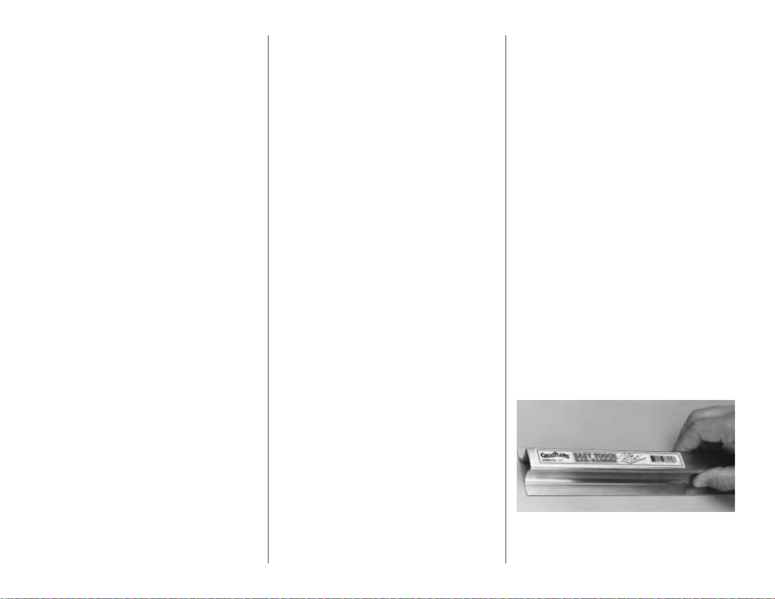
EASY-TOUCH™BAR SANDER
A flat, durable, easy to handle sanding tool is a
necessity for building a well finished model. Great
Planes makes a complete range of Easy-Touch Bar
Sanders (patented) and replaceable Easy-Touch
4
Page 5
Adhesive-backed Sandpaper. While building the
Contender we used two 5-1/2" [140mm] Bar Sanders
and two 1 1" [280mm] Bar Sanders equipped with 80grit and 150-grit Adhesive-backed Sandpaper.
Here's the complete list of Easy-Touch Bar Sanders
and Adhesive Backed Sandpaper.
5-1/2" [140mm] Bar Sander (GPMR6169)
11" [280mm] Bar Sander (GPMR6170)
22" [560mm] Bar Sander (GPMR6172)
33" [840mm] Bar Sander (GPMR6174)
44" [1120mm] Bar Sander (GPMR6176)
11" [280mm] Contour Multi-Sander (GPMR6190)
12' [300mm] roll of Adhesive-backed sandpaper:
80-grit (GPMR6180)
150-grit (GPMR6183)
180-grit (GPMR6184)
220-grit (GPMR6185)
Assortment pack of 5-1/2" [140mm] strips (GPMR6189)
We also use Top Flite 320-grit (TOPR8030, 4 sheets)
and 400-grit (TOPR8032, 4 sheets) wet-or-dry
sandpaper for finish sanding.
IMPORTANT BUILDING NOTES
There are two types of screws used in this kit:
Sheet metal screws are designated by a number
and a length.
For example #6 x 3/4" [19.1mm]
Machine screws are designated by a number,
threads per inch and a length.
For example 4-40 x 3/4" [19.1mm]
When you see the term test fit in the instructions, it
means that you should first position the part on the
assembly without using any glue, then slightly
modify or custom fit the part as necessary for the
best fit.
Whenever the term glue is used you should rely
upon your experience to decide what type of glue to
use. When a specific type of adhesive works best for
that step we will tell you what type of glue to use.
Whenever just epoxy is specified you may use either
30-minute epoxy or 6-minute epoxy. When 30-minute
epoxy is specified it is highly recommended that you
use only 30-minute (or 45-minute) epoxy because you
will need the working time and/or the additional strength.
Occasionally we refer to the top or bottom of the
model or up or down. To avoid confusion, the top or
bottom of the model is as it would be when the
airplane is right side up and will be referred to as the
top even if the model is upside down during that
step, i.e. the top main spar is always the top main
spar even if the wing is upside down when you are
working on it. Similarly, move the former up means
move the former toward the top of the fuselage even
if the fuselage is upside down when you are working
on it.
When you get to each step, read that step completely
through to the end before you begin. Frequently
there is important information or a note at the end of
the step that you need to know before you start.
Photos and sketches are placed ahead of the step
they refer to. Frequently you can study photos in
following steps to get another view of the same parts.
COMMON ABBREVIATIONS
Deg = degrees Elev = elevator
Fuse = fuselage " = inches
LE = leading edge Ply = plywood
Stab = stabilizer TE = trailing edge
LG = landing gear mm = millimeters
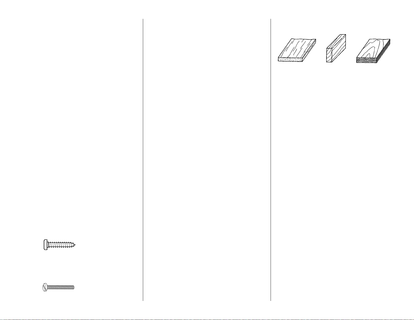
TYPES OF WOOD
BALSA BASSWOOD PLYWOOD
Metric Conversion Chart
1” = 25.4mm (conversion factor)
Note: An inch/mm scale is provided on the
fuselage plan.
1/64" = .4mm
1/32" = .8mm
1/16" = 1.6mm
3/32" = 2.4mm
1/8" = 3.2mm
5/32" = 4mm
3/16" = 4.8mm
1/4" = 6.4mm
3/8" = 9.5mm
1/2" = 12.7mm
5/8" = 15.9mm
3/4" = 19mm
1" = 25.4mm
2" = 50.8mm
3" = 76.2mm
6" = 152.4mm
12" = 304.8mm
15" = 381mm
18" = 457.2mm
21" = 533.4mm
24" = 609.6mm
30" = 762mm
36" = 914.4mm
5
Page 6
6
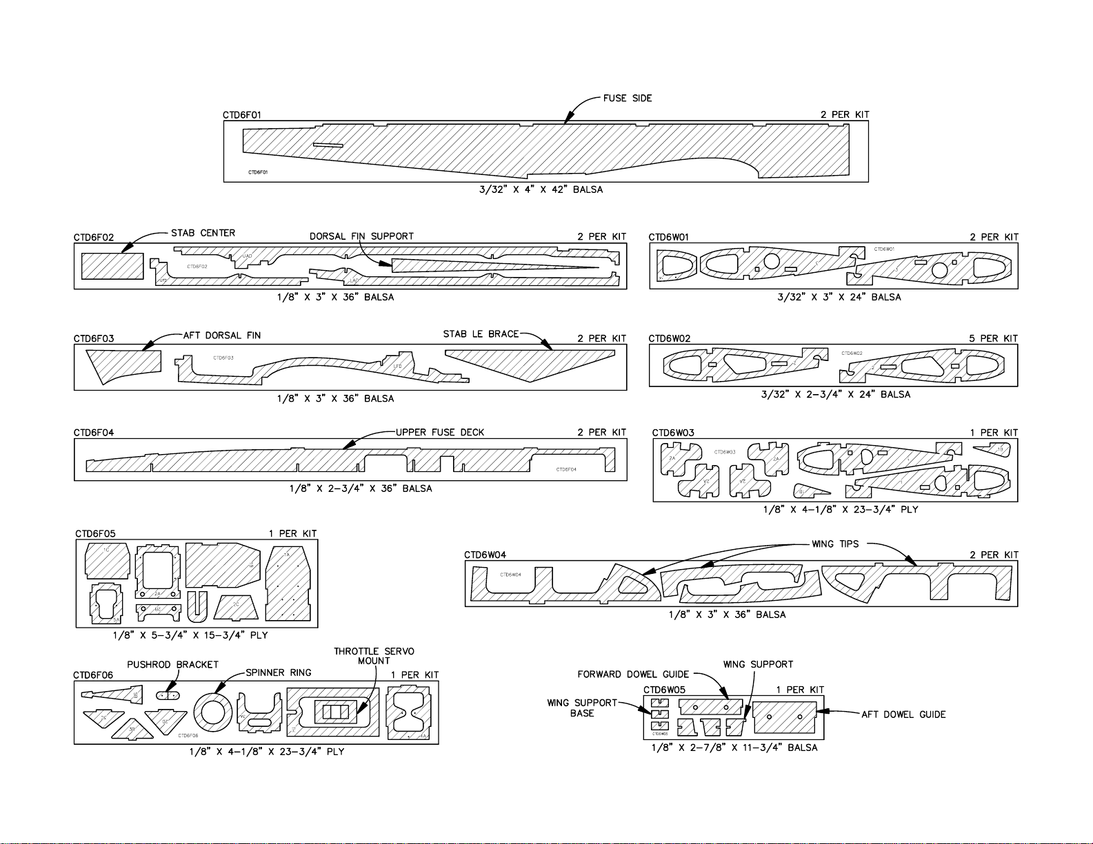
DIE-CUT PATTERNS
Page 7
GET READY TO BUILD
1. Unroll the plan sheets. Roll them inside out so
they lie flat.
2. Remove all the parts from the box. Use a ballpoint
pen (not a felt tip pen) to lightly write the name or
size on each piece so you can identify it later. Use
the die-cut patterns on page 6, to identify and mark
the die-cut parts before you remove them from their
die sheets. Many of the parts already have numbers
stamped on them, but in some cases the number is
located alongside the parts or only on the die
drawings. You may remove all the die-cut parts from
their die sheets now or wait until you need them. If a
part is difficult to remove, don't force it out but cut
around it with a #11 blade. After you remove the
parts from their die sheets, lightly sand the edges to
remove slivers or die-cutting irregularities. Save
some of the larger leftover pieces of wood.
3. Separate the parts into groups such as stab, fin,
wing, and fuse. Store smaller parts in zipper-top
food storage bags.
BUILD THE TAIL SURFACES
Build the stab
❏ 1.Work on a flat surface over the plan. Pin the stab
plan to the building board and cover the plan with
Plan Protector. Refer to the plan to identify the parts
and their location. The plan may be cut apart on the
dashed lines if space is a problem.
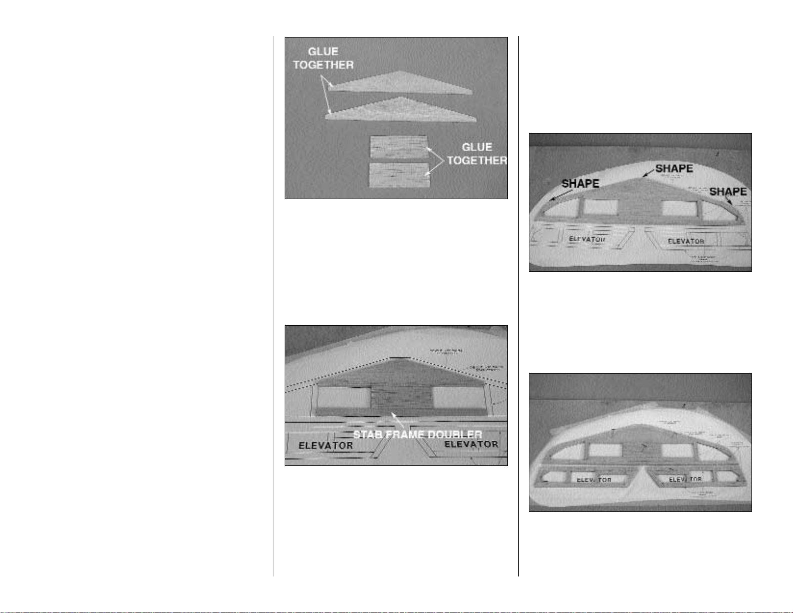
❏ 2. Locate and glue the two die-cut 1/8" [3.2mm]
balsa LE braces together to form one 1/4" LE brace.
Locate and glue the two die-cut 1/8" [3.2mm] balsa
stab centers together to form one 1/4" stab center.
❏ 3. Glue the die-cut 1/8" balsa stab center to the LE
brace as shown on the plan.
❏ 4. Pin the center section to the plan.
❏ 5. Locate the 1/4" x 3/8" x 12" [6.4 x 9.5 x 305mm]
basswood stab brace. Cut it to a length of 11" then
glue it to the aft edge of the stab center in the
location shown on the plan.
❏ 6. Use two 1/4" x 3/8" x 30" [6.4 x 9.5 x 762mm]
balsa sticks to make the frame for the stab. Cut the
sticks to the length shown on the plan and glue them
together to form the stab.
❏ 7. Use leftover pieces of the 1/4" x 3/8" x 30" [6.4
x 9.5 x 762mm] balsa sticks to make the 1/4"
[6.4mm] balsa gussets. Cut them as shown on the
plan and glue them in place.
❏ 8. Remove the stab from the plan. Shape the
corners and the center LE of the stab assembly as
shown on the plan. Pin the stab back to the building
board after you have shaped the stab.
❏❏9. Use two 1/4" x 3/8" x 30" [6.4 x 9.5 x 762mm]
balsa sticks to make the frames for the elevator. Cut
the sticks to the shape shown on the plan. Glue the
sticks together the same way the stab was
assembled. Make a left and right elevator.
7
Page 8
❏❏10. Insert a T-pin through the center of the
elevator LE near the tip and near the root. Place a
straightedge across the T-pins and draw a
centerline on the elevator LE with a ball point pen.
This line is used as a reference when we install the
hinges in a later step. Draw a centerline along the TE
of the stab the same way.
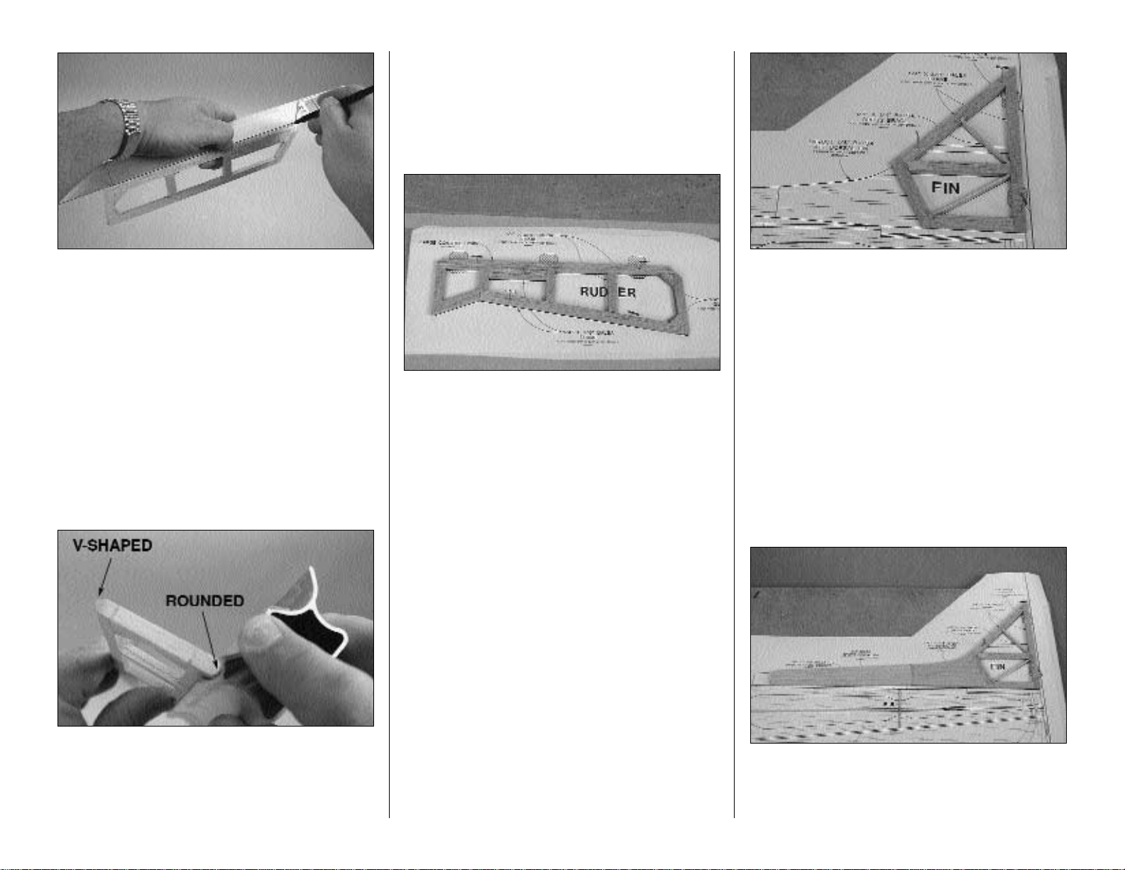
❏❏11. Shape the LE of the elevator to a “V” as
shown on the plan. Use the line you have drawn as
a reference when sanding the LE.
❏❏12. Final sand the stab and elevator. Shape the
LE of the stab and the TE of the elevator as shown
in the cross-section on the plan. Hint:The Great
Planes Easy Touch Multi-Sander works great for
shaping the round LE and TE.
Build the rudder
❏ 1.Work on a flat surface over the plan. Pin the
rudder plan to the building board and cover the plan
with Plan Protector. The plan may be cut apart if
space is a problem.
❏ 2. Use one 1/4" x 3/8" x 30" [6.4 x 9.5 x 762mm]
balsa stick and leftover pieces of 1/4" x 3/8" x 30"
[6.4 x 9.5 x 762mm] balsa stick from the stab and
elevator to make the frame for the rudder. Cut the
sticks to the shape shown on the plan. Glue the
sticks together the same way the stab and elevator
were assembled.
❏ 3. Draw a centerline on the rudder LE the same
way it was done to the elevator.
❏ 4. Final sand the rudder. Shape the LE to a “V” the
same way it was done for the elevator and as shown
on the plan.
❏ 5. Shape the TE, top and bottom of the rudder to
the rounded shape shown on the plan.
Build the fin
❏ 1. Pin the fuselage plan to the building board and
cover the plan with Plan Protector.
❏ 2. Use one 1/4" x 3/8" x 30" [6.4 x 9.5 x 762mm]
balsa stick to make the frame of the fin. Cut the stick
to the lengths shown on the plan. Pin the sticks in place
as needed. Glue the sticks together to form the fin.
❏ 3. From 1/8" x 1/4" x 30" [3.2 x 6.4 x 762mm] balsa
stick, cut the cross braces and glue them in place at
the location shown on the plan.
❏ 4. Glue the two die-cut 1/8" [3.2mm] balsa aft
dorsal fin halves together, laminating them to make
a 1/4" [6.4mm] dorsal fin.
❏ 5. From 1/4" x 3" x 24" [6.4 x 76 x 610mm] balsa
sheet, cut the center dorsal fin to the size and
shape shown on the plan.
❏ 6. Glue the aft dorsal fin to the fin. Glue the center
dorsal fin to the aft dorsal fin. All of these parts must
be lying on a flat surface while gluing, to ensure a
flat, straight assembly.
8
Page 9
❏ 7. Remove the assembly from the plan.
❏ 8. Final sand the fin assembly. Shape the LE of the
fin and the top of the dorsal fin to the shape shown
on the plan.
❏ 9. Draw a centerline on the TE of the fin in the
same manner as was done for the stab.
Install the hinges
❏ 1. Mark the location of the hinge slots on the
elevator halves, stab, fin and rudder where shown on
the plan.
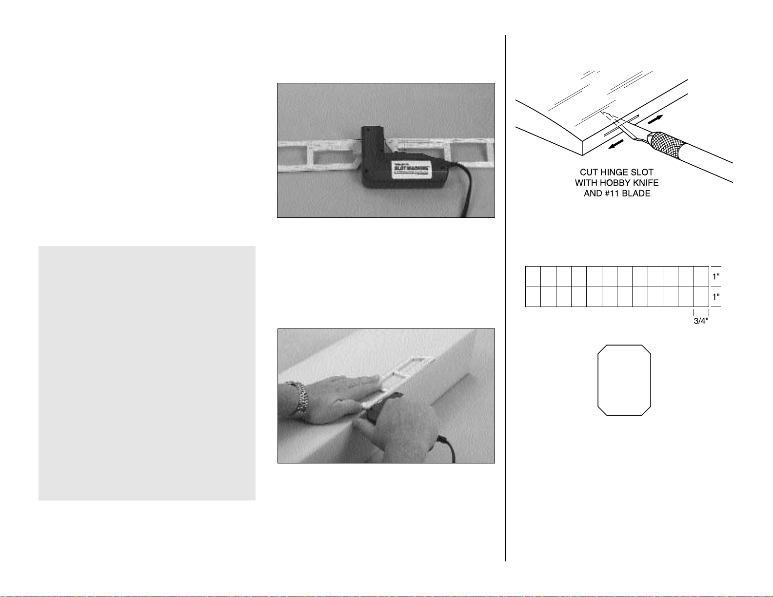
We have simplified the task of cutting hinge slots
with the introduction of the Great Planes Slot
Machine™. This simple electric tool cuts a perfect
width slot for use with CA hinges.
To cut the hinge slot place the blades onto the wood
where you want the slot. Lightly press the teeth into
the wood. When you are satisfied with the location
press the button on the handle and the blades will
cut easily into the balsa wood.
If you choose not to purchase a Slot Machine you
can make the slots following these instructions.
❏ 2. Cut the hinge slots in the elevators, stab, fin and
rudder along the centerlines you marked earlier with
a #11 blade.
❏ 3. Using the sketch above, cut nine hinges from
the CA hinge strip supplied with the kit. Snip the
corners off so they go into the slots easier. You may
cut all nineteen hinges that will be used for the
airplane or just cut them as you need them.
❏ 4. Test fit the hinges into the slots. If the hinges do
not slide into the slots easily, work your knife blade
back and forth in the slot a few times to provide more
clearance (it is really the back edge of the blade that
does the work here in widening the slot).
IMPORTANT NOTES ABOUT CA HINGES
This kit is supplied with a CA hinge material
consisting of a 3-layer lamination of Mylar and
polyester. It is specially made for hinging model
airplane control surfaces. When properly installed,
this type of CA hinge provides the best combination
of strength, durability and easy installation. We trust
all of our Gold Edition warbirds to these hinges, but
it is essential to install them correctly. Carefully
follow the hinging instructions in this manual for the
best result.
The most common mistake made by modelers when
installing CA hinges is making the hinge slots too
tight restricting the flow of CA to the back of the
hinges; or not using enough glue to fully secure the
hinge over its entire surface area. This results in
hinges that are only tack glued into the hinge slots.
The techniques for cutting the hinge slots and gluing
in CA hinges (near the end of the manual) have been
developed to ensure thorough and secure gluing.
9
Page 10
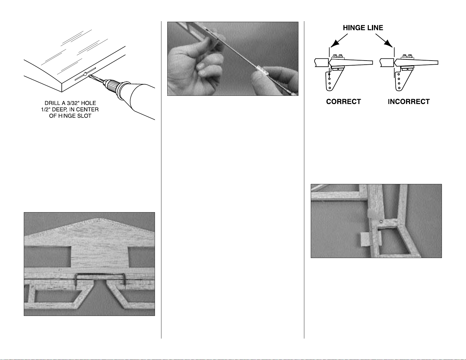
❏ 5. Drill a 3/32" [2.40mm] hole, 1/2" [13mm] deep in
the center of the hinge slots. Use a rotary tool with a
3/32" [2.40 mm] drill bit or a carbide cutter for the
best results. Re-insert your knife blade to clean out
the slot after you drill the hole.
❏ 6. Test fit the elevator halves to the stab with
the hinges.
❏ 7. Position the elevator joiner wire on the trailing
edge of the stab and center it between the elevators.
Mark the LE of both elevators where the joiner will enter.
❏ 8. Cut a slot in the leading edge of both elevator
halves to accommodate the joiner wire. This can be
done easily with the Great Planes “Groove
Tube”™ as shown in the photograph. Hint: If you do
not have a Groove Tube, use a 5/32" [4mm] brass
tube sharpened at one end to cut the slot.
❏ 9. Accurately drill holes in the elevators for the 1/8"
joiner wire. Begin by drilling a 1/16" [1.6mm] pilot
hole. Then drill the final hole to a depth of 7/8"
[22.2mm] with a 9/64" [3.6mm] drill bit. (The hole is
drilled slightly oversize to allow for positioning and to
create a hard epoxy “sleeve” around the wire).
❏ 10. Roughen the joiner wire with coarse sandpaper,
then clean the wire thoroughly with alcohol to remove
any oily residue.
❏ 11. Test fit the joiner wire into the elevators. Then,
glue it in using epoxy. When gluing, lay the elevators
on a flat surface with the LE along a straightedge to
insure perfect alignment. Cover the top of the joined
elevators with a sheet of wax paper. Then, lay a flat,
heavy object on top. A telephone book works well.
This will insure a true flat elevator assembly when
the epoxy cures.
Install the control horns
❏ 1. Place a large control horn at the location
indicated on the elevator plan and rudder plan. Use
a ballpoint pen to mark the location where the holes
need to be drilled.
❏ 2. Check for correct alignment. Drill two 3/32"
[2.4mm] holes for the control horn mounting bolts
through the rudder .
❏❏3. Repeat step 2 for the right half of the elevator.
❏ 4. Apply a small drop of thin CA in the holes to
harden the wood. Redrill the holes after the CA
has hardened.
❏ 5. Attach the control horn to the left side of the
rudder with two 2-56 x 1/2" [12.7mm] machine
screws.
❏ 6. Attach the control horn to the bottom right side
of the elevator with two 2-56 x 1/2" [12.7mm]
machine screws.
There, that went pretty quick. If your workbench is a
mess, clean it off and get ready to move on to the wing!
10
Page 11

BUILD THE WING
Build the bottom of the wing
❏ 1. Cut the wing plan on the dashed line. Tape the
two wing plan halves together to form the full plan for
the wing.
❏ 2. Work on a flat surface over the plan. Pin or tape
the wing plan to the building board and cover the
plan with Plan Protector.
❏ 3. When building the wing it is important to note that
the wing is being built upside-down over the plan.
❏ 4. Locate four die-cut 3/32" [2.4mm] balsa W-2
ribs and four die-cut 1/8" [3.2mm] ply W-2A
doublers. Glue a W-2A doubler to each W-2 rib with
6-minute epoxy. Make sure that you make two for
the left wing and two for the right wing.
❏ 5. After the epoxy has cured, remove the area on
W-2 that will hold the landing gear block. Do this on
all four of the assemblies that you just glued together.
❏ 6. Locate two die-cut ply W-1 ribs and two die-cut
ply W-1B doublers. Glue a W-1B doubler to each
W-1 rib with 6-minute epoxy. Make sure that you
make one left side and one right side when gluing
them together.
❏ 7. Cut the two 1/4" x 3/8" x 48" [6.4 x 9.5 x
1220mm] basswood wing spars to the length shown
on the plan. Pin one of the wing spars to the plan.
Make sure that the pins will not be in the way for
placing any of the ribs on the spar.
❏ 8. Position ribs W-1, W-2 and W-3 on the wing
spar at the locations indicated on the plan. Make
sure when you place the ribs that all of the ribs have
the jig tab in contact with the building board. Place
the remaining wing spar in position on the bottom of
the wing in the notches on the ribs W-1, W-2 and W-
3. When positioning the ribs be sure the ribs are
perpendicular to the building table. When you are
satisfied with the fit glue the ribs to the bottom wing
spar only. It is important to remember you are
building the wing upside down. Be sure to glue only
the bottom wing spar.
❏ 9. Locate two 9/16" x 7/8" x 24" [14.3 x 22.2 x
584mm] balsa TE sticks. Glue the two TE sticks
together where they will meet at the center of the
wing. Test fit the TE on the wing jig tabs. When you
are satisfied with the fit glue the TE to the end of the
ribs only! Do not glue the TE to the jig tabs.
❏ 10. Cut off the excess TE material outboard of the
tip rib.
11
Page 12

❏ 11. Locate the die-cut 1/8" [3.2mm] ply forward
dowel guide and the die-cut 1/8" [3.2mm] ply aft
dowel guide. Measure the distance between the
center of the holes in the forward dowel guide. Draw
a centerline on the forward dowel guide.
❏ 12. Use 6-minute epoxy to glue the die-cut 1/8"
[3.2mm] ply forward dowel guide and the die-cut 1/8"
[3.2mm] ply aft dowel guide in place between the two
W-1 ribs as shown on the plan. Be sure that the side
of the forward dowel guide with the centerline on it is
facing the front of the wing.
❏ 13. Locate the two die-cut balsa 3/32" [2.4mm] half
ribs W-1A. There is a pin punch mark on the top of
each rib. Glue the two W-1A ribs to each other
forming one 3/16" W-1A rib. Make sure that the
punch marks are aligned.
❏ 14. Glue the W-1A rib assembly in place between
the W-1 ribs in the location shown on the plan. W-1A
supports the wing sheeting you will be adding later
so make sure it is properly centered. Glue W-1A in
position with the side of the rib with the pin punch
nearest your building board.
❏❏15. Locate two 3/32" x 1-1/4 “ x 30" [2.4 x 32 x
762mm] balsa sub LE sticks. Test fit the sub LE
against the front of the ribs on the right side of the
wing making sure that each rib comes in contact with
the sub LE. Sand the front of the ribs as needed.
When you are satisfied with the fit, glue the sub LE
to the front of the ribs and the front of the forward
dowel guide. Be sure that the joining of the two sub
LE sticks is directly over the centerline that you
drew on the forward dowel guide.
❏❏16. Sand the sub LE stick so that it is flush with
the wing ribs.
❏17. Repeat step 15 and 16 for the left side of the wing.
❏❏18. Locate the two maple landing gear rails and
two maple torque blocks. Measure in from the end of
the landing gear rail 1/4" [6.4mm]. Mark a line with a
pen. Use 6-minute epoxy to glue a torque block to
one of the landing gear rails at the mark you just
made. Do the same for the remaining landing gear
rail and torque block. Set it aside and allow the
epoxy to cure.
❏❏19. From the 1/4" x 1/4" x 18" [6.4 x 6.4 x
457mm] basswood stick, cut four 2" [51mm] sticks to
be used for the servo rails. Glue two rails into the
slots in the two W-3 ribs in the left wing. The slot in
the aft of rib W-3 is longer than the forward slot. This
is to allow you to get exact spacing for your brand of
servo. Be sure to position the rear servo rail for your
servo. Glue them in place when you are satisfied
with the fit.
❏20. Repeat step 19 for the servo rails in the right wing.
❏ 21. If you plan to install the optional flap, (and if
you’re not, how come? It really is a lot of fun and
adds another dimension to flying the Contender!) cut
two additional 4-1/4" [108.4mm] servo rails from the
remainder of the 1/4" x 1/4" x 18" [6.4 x 6.4 x 457mm]
basswood stick. These will serve as the servo rails
for the flap servo. Install these in the slots between
the two W-1 ribs in the same way you did for the
aileron servos.
CCoonntteennddeerr FFuunn FFaacctt
The original Contender was designed by
renowned scale modeler Dave Platt in 1969!
12
Page 13

❏ 22. Glue the 1/4" x 1" x 3-29/32" [6.4 x 25.4 x
99mm] basswood wing bolt plate in place between
the W-1 ribs and onto the doublers W-1B with
6-minute epoxy.
❏❏23. By now your landing gear rail assembly
should have cured. Drill a 5/32" [4mm] hole through
both of the landing gear rails and the torque blocks.
Drill from the side of the landing gear rail that has the
groove. As you drill, make sure you hold the drill at a
90 degree angle to the landing gear rail and that the
hole is centered in the torque block.
❏❏24. Use 6-minute epoxy to glue the landing gear
rail assembly to the slots in W-1 and W-2. Be sure that
you glue the torque block securely to W-1 when gluing
the rail in place. Do this for both sides of the wing.
❏ 25. Locate one of the 3/32" x 3" x 24" [2.4 x 76 x
610mm] balsa wing sheets. Cut it into four pieces
3/32" x 3/4" x 24" [2.4 x 19.1 x 610mm].
❏26. See the Hot Tip that follows, then glue one of the
3/32" x 3" x 24" [2.4 x 76 x 610mm] balsa sheets to
one of the 3/32" x 3/4" x 24" [2.4 x 19.1 x 610mm]
balsa sheets to make one 3-3/4" [95mm] sheet. Make
four sheets for the top and bottom LE wing sheeting.
❏❏27. Test fit the wing skin sheeting. The sheeting
should join at the center of the rib W-1A and be
against the notch in the rib. Glue the wing skin
sheeting in place on top of the spar and against the
notch in the rib. When the glue has cured apply a bead
of glue to the top of each rib and along the sub LE. Pull
C. Turn the sheet over and apply weights on top of
the sheet to hold it flat. Apply thin CA sparingly to
the seam between the two pieces, quickly wiping
away excess CA with a paper towel as you proceed.
D. Turn the sheet over and remove the masking
tape, then apply thin CA to the seam the same
way you did for the other side.
E. Sand the sheet flat and smooth with your bar
sander and 150 grit sandpaper.
B. Use masking tape to tightly tape the two
sheets together joining the trimmed edges.
A. Use a metal straightedge as a guide to trim
one edge of both sheets.
WING SHEETING
13
Page 14

the sheeting down making sure it contacts the surface
of each rib and the sub LE. Hold it in place until the
glue has cured.
❏❏28. Trim the sheeting flush to the wing sub LE.
❏ 29. Repeat steps 27 and 28 for the other side of the
wing. Be sure that you glue the sheeting securely at the
center of the wing where the sheeting comes together.
❏ 30. From one 3/32" x 3" x 30 [2.4 x 76 x 762mm]
balsa sheet cut three pieces 3" x 4-5/16" [76 x
1 10mm]. Edge glue the three pieces in the same way
that was done for the LE sheeting.
❏ 31. Cut the bottom center sheeting template from
the plan. Trace the pattern onto the balsa sheets that
were just glued together. Cut the balsa sheet to match.
❏ 32. Test fit the balsa sheeting to the center of the
bottom of the wing between the W-1 ribs. When you
are satisfied with the fit, glue it in place.
❏ 33. From the leftover 3/32" x 3" x 30" [2.4 x 76 x
762mm] balsa sheet, cut two 3" x 1-3/4" [76 x 44mm]
sheets to be used as the sheeting around the aileron
servos. Fit the sheets and glue them in place.
❏ 34. Cut an opening in the aileron sheeting to
accommodate the size of your particular brand
of servo.
❏ 35. Use a razor plane to shape the 9/16" x 7/8"
[14.3 x 22.2mm] TE that you glued in place in step 9.
Shape the TE to match the airfoil of the ribs.
❏ 36. Sand the entire bottom of the wing.
Build the top of the wing
❏ 1. Remove the wing from the building board. Turn
the wing over and place it over the plan and we’ll
finish the wing construction.
❏ 2. Locate the die-cut 1/8" [3.2mm] ply wing
support and base. Slide the base into the wing
support and glue them together. Make three
assemblies
❏ 3. Place a wing support under the center rib, the
left tip rib and the right tip rib. These will support the
wing on the workbench while sheeting and sanding
the top of the wing. Apply a couple of weighted bags
on the wing to hold it firmly on the workbench.
14
Page 15

❏ 4. Fully seat the top wing spar in the rib notches and
glue in place. The jig tabs on ribs W-1 must be sanded
off prior to sheeting.
❏ 5. Sheet the LE of the wing in the same way you
did the sheeting on the bottom of the wing. Sheet
both the left and right side of the wing.
❏ 6. Trim the sheeting flush to the wing sub LE.
❏ 7. Cut the jig tabs from the ribs. Lightly sand the ribs
even with the trailing edge. Make sure when you cut
them off that you maintain the airfoil of the rib.
❏ 8. Cut fourteen 3" x 2-1/8" [76 x 54.2mm] balsa
shear webs from leftover 3/32" x 3" x 30" [2.4 x 76 x
762mm] balsa sheet. Cut two 2-1/8" x 1-1/2" [54.2 x
38mm] balsa shear webs.
❏ 9. Glue one of the 1-1/2" x 2-1/8" [38 x 54.2mm]
balsa shear webs in place between the W-3 ribs for
both wing halves. Glue the 2-1/8" x 3" [54.2 x 76mm]
balsa shear webs between each of the remaining
ribs. The shear webs will need to be trimmed slightly
on the W-2 ribs that have the ply doublers. At the
center of the wing use two shear webs and trim them
to fit the center section.
❏ 10. From the leftover 3/32" x 3" x 30" [2.4 x 76 x
762mm] balsa, sheet the center section of the wing.
If you will be installing the optional flap, mark the
servo location and cut the opening for it.
❏ 11. Sand the entire top of the wing.
❏ 12. Locate the two 1/2" x 1-1/4" x 24" [12.7 x 32 x
610mm] balsa LE sticks. Glue them to the front of
the balsa sub LE. Be sure the LE sticks are joined
directly over the joint of the sub LE stick. Trim the
end of the LE flush with the tip rib.
❏ 13. Use a razor plane to shape the wing LE to the
shape shown on the plan. Sand the wing LE to its
final shape.
❏ 14. Measure over 1" from each side of the leading
edge joint and mark it with a pen. Be sure the mark
is centered on the LE.
❏ 15. On the marks that you have made, push a
T-pin through the balsa LE, sub LE and the forward
dowel guide. The pin should be centered in the hole
in the forward dowel guide.
❏ 16. Using the pin holes in the LE as a reference,
drill a 1/8" pilot hole through the LE. Check to make
sure the hole is centered in the hole of the forward
dowel guide. Then drill a 1/4" [6.4mm] hole through
the LE. It will line up perfectly with the holes in the
forward dowel guide.
❏ 17. Locate two 1/4" x 4" [6.4 x 25.4mm] hardwood
wing dowels. Round one end of each dowel as
shown on the plan. Slightly round the other end for
ease of insertion.
❏ 18. Apply 30-minute epoxy to the holes in the
forward and aft dowel guide. Slide one dowel into
each hole, making sure that the rounded end
protrudes through the LE and that the other goes all
the way through both dowel guides.
15
Page 16

Build the ailerons
❏❏1. Locate a 1/4" x 3/8" x 30 [6.4 x 9.5 x 762mm]
balsa stick. Using the plan as a guide, cut the stick
as shown on the plan and glue the pieces together to
make the aileron.
❏❏2. Remove the aileron from the plan. Make a
mark at the center of the aileron at each end and
place a T-pin at each mark. Place a straightedge
along the aileron LE at the pins and draw a
centerline on the aileron LE.
❏❏3. Mark the location of the hinges and cut the
hinge slots using the same technique used for the
elevator and the rudder.
❏❏4. Shape the LE to a “V” and round the TE as
shown on the plan.
❏ 5. Repeat steps 1 - 4 for the other aileron.
Install the aileron control horns
❏❏1. Place a large control horn on the bottom of
the right aileron as indicated on the aileron plan. Use
a ballpoint pen to mark the location where the holes
need to be drilled.
❏❏2. Drill two 3/32" [2.4mm] holes for the control
horn mounting bolts through the right aileron.
❏❏3. Apply a small drop of thin CA in the hole to
harden the wood. Redrill the hole after the glue cures.
❏❏4. Attach the control horn to the right aileron with
two 2-56 x 1/2" [12.7mm] machine screws.
❏ 5. Repeat steps 1 through 4 for the left aileron.
Build the flap
❏ 1. You must build the flap regardless of whether
you are going to have it operational or fixed. The
construction steps are the same.
❏ 2. From 1/4" x 3" x 30" [6.4 x 76 x 762mm] balsa
sheet, cut the 1/4" [6.4mm] balsa flap TE doubler as
shown on the plan. Pin it in place on the plan.
❏ 3. Build the flap frame from 1/4" x 3/8" x 30" [6.4
x 9.5 x 762mm] balsa sticks. Cut the sticks and glue
them in place as shown on the plan.
❏ 4. Cut the 1/8" x 1/4" [3.2 x 6.4mm] balsa flap
diagonal braces as shown on the plan. When
satisfied with the fit glue them in place.
❏ 5. Sand both sides of the flap.
❏ 6. Round the flap TE as shown on the flap
cross section.
CCoonntteennddeerr FFuunn FFaacctt
In the 1970’s the Contender was one of the
“must have” models. It was extremely popular
as a sport plane and was particularly well
suited as a fun fly contest airplane.
16
Page 17

Perform step 7 only if you are NOT going to have
a functional flap.
❏ 7. Glue the flap in position in the center of the wing
at the location shown on the plan.
Steps 8 - 12 are for building the functional flap.
❏ 8. Draw a centerline on the leading edge of the
flap the same way it was done for the aileron.
❏ 9. Mark the location for the hinges and cut the
hinge slots.
❏ 10. Using the centerline as a reference taper the
LE to a “V” as shown on the flap cross-section.
❏ 11. Mark the location for the flap hinges on the
wing TE and cut the hinge slots.
❏ 12. Install the control horn on the top of the flap as
shown on the plan. Use the same installation method
used on the aileron.
Build the wing tips
❏ 1. Locate the 1/8" [3.2mm] die-cut balsa wing tip
parts. Each wing tip consists of two halves. Glue the
left and right halves together. Do this to make four
wing tips.
❏ 2. Glue two wing tip assemblies together to make
one 1/4" [6.4mm] wing tip. Do the same for the other
wing tip.
❏ 3. Sand the wing tip edges round just as you did
for the TE of the aileron.
Before we can continue, you’ll need to decide which
wing tip shape you wish to use on your Contender.
The standard tip is the original “nostalgia” tip shape
and the model performs quite nicely with this tip. The
optional tip shape was evolved onto the original
Contender design to make its handling even better,
particularly eliminating a “roll coupling from rudder”.
With the optional wing tips, your model will just yaw
upon rudder application, without the need to use
opposite aileron to correct a roll couple. Additionally,
your Contender will have even better slow speed
handling, without any loss of aerobatic performance.
Note that the model flew excellently in both
configurations and the decision to install or not to
install the optional tips is not a crucial one for basic
flight handling.
Standard wing tip
❏❏1. Glue the wing tip into the slots in the tip ribs
of the wing. Make sure the wing tip is aligned at the
center of the wing LE and TE.
❏❏2. Locate the 1/8" x 1-3/8" x 30" [3.2 x 34.9 x
762mm] balsa sheet and cut four wing tip braces for
each wing tip. Use the above sketch and photos as
a guide when cutting the braces. Position the braces
as shown on the plan then glue them in place when
you are satisfied with the fit.
CCoonntteennddeerr FFuunn FFaacctt
When the Contender was originally introduced
it was advertised as “Buildable in 8 hours”
and the instructions consisted of 12 sketches.
We are not so sure about the 8 hours but
we are sure you will like this expanded
construction manual.
17
Page 18

❏❏3. From the 1/2" x 1/2" x 6" [12.7 x 12.7 x
152mm] balsa stick, cut two wing tip blocks and
glue them in position as shown on the plan. One
block is glued on each side of the wing tip.
❏❏4. Sand the wing tip blocks to shape.
❏ 5. Repeat steps 1 - 4 for the other wing tip.
Optional wing tip
❏❏1. Test fit the wing tip into the slots in the tip rib.
Make sure there is enough room in the slots for the wing
tip to be slanted upward approximately 40 degrees.
❏❏2. On the wing plan, locate the templates for the
four optional wing tip braces. Cut one of each
brace from the 1/8" x 1-3/8" x 30" [3.2 x 34.9 x
762mm] balsa sheet.
❏❏3. Use the braces as a gauge to set the wing tip
angle and glue the wing tip in position.
❏❏4. Glue the braces in position as shown on the
plan and in the above photographs. Two braces are
located on each side of the wing tip.
❏❏5. From the 1/2" x 1/2" x 6" [12.7 x 12.7 x
152mm] balsa stick cut two wing tip blocks and
glue them in position as shown on the plan. One
block is glued on each side of the wing tip.
❏❏6. Sand the wing tip blocks to shape.
❏ 7. Repeat steps 1 - 6 for the other wing tip.
Install the aileron and flap hinges
❏ 1. If you have been following the instructions you
should already have the hinge slots located in the
leading edge of the ailerons and flap. Hold the
aileron in place on the wing and mark the location
where the hinge slots need to be cut into the wing
TE. Do this for both aileron locations.
❏ 2. If you are making the functional flap, hold the
flap in place and mark the location where the hinge
slots need to be cut into the wing TE.
❏ 3. Cut all of the aileron and flap slots into the TE
of the wing.
❏ 4. Place all of the control surfaces in place with the
hinges to make sure that everything is properly
positioned. When you are satisfied that everything
fits, remove the control surfaces from the wing. Final
hinge installation will be done after the covering has
been completed.
BUILD THE FUSELAGE
Frame the fuselage
As we go through the next few steps it is important
to note that we are building the fuse
upside-down over the plan.
❏ 1.Work on a flat surface over the plan. Pin or tape
the fuselage plan to the building board and cover
the plan with Plan Protector.
18
Page 19

❏ 2. Locate the two die-cut 1/8" [3.2mm] balsa upper
fuse deck halves. Glue them together and then pin
them over the fuselage bottom view.
❏ 3. Drill a 3/16" [4.8mm] hole in the punch marks on
formers F-2A, F-2B, F-4A and F-5A. These will
accommodate the pushrod installation as we build
the fuse.
❏ 4. Locate the 1/8" [3.2mm] die-cut ply former F-2A
and F-2B. Use 6-minute epoxy to glue F-2B to F-2A,
aligning the 1/4 holes in the formers.
❏ 5. Test fit formers F-2A, F-3A, F-4A and F-5A into
the slots in the upper fuse deck with the lettering
facing forward. Use a small triangle to make sure the
formers are perpendicular to the upper fuse deck,
then glue the formers in place.
❏❏6. Locate the die-cut 1/8" [3.2mm] balsa lower
aft fuse doubler (LAD), upper aft fuse doubler
(UAD), lower fuse doubler (LFD) and the upper
forward fuse doubler (UFD). Glue them in place on
the die-cut 3/32" [2.4mm] balsa fuselage side. The
doublers should be positioned so the tabs on the
front of the doublers are flush with the fuse front. Be
sure when you glue the doublers to the fuselage side
that you make a left and right fuselage side.
❏ 7. Repeat step 6 for the other fuselage side.
❏ 8. Glue the left fuselage side in place on the upper
fuse deck and to each of the fuselage formers. Do
the same for the right side of the fuselage.
❏ 9. Use some 120-grit sandpaper to roughen the
plastic outer pushrod tubes where they will come in
contact with the fuselage formers and the slot in the
side of the fuselage. Working from the open fuse
bottom, route the tubes though the F-4A, F5A and the
fuse sides. Make sure both pushrod guides extend
1/2" as shown. The tubes should also protrude at least
1" from the fuse side exits. Glue both pushrod guides
to each former and the fuse side.
❏ 10. Fill any gaps around the outer pushrod guide
tubes with a lightweight filler such as Hobbico
19
Page 20

HobbyLite™. Allow the filler to completely harden.
Trim the protruding pushrod guide tube to within 1/8"
from the fuse side. Then with a sanding block and
150-grit sandpaper, sand the pushrod guide tube
and filler material flush with the fuse side.
❏ 11. Locate the 2" [51mm] long balsa tapered tail
post and glue it in place at the end of the fuselage.
Sand it flush with the top and bottom of the fuse.
Sand the edges of the fuse bottom to be flush with
the fuse sides.
❏ 12. Remove the pins holding the fuselage to the
building board.
❏ 13. Sand the bottom of the fuse smooth. Using
3/32" x 3" x 30" [2.4 x 76 x 762mm] balsa, cut and
glue the sheets to the bottom of the fuselage. Cut the
balsa so that the grain of the sheeting is running
across the fuselage as shown on the plan crosssections. When you have finished gluing the
sheeting in place, sand it flush with the fuse sides.
❏ 14. Edge glue two pieces of 3/32" [2.4mm] balsa
and cut it to fit the area where the flap rests on the
fuselage bottom. Do this even if you are not installing
the functional flap.
❏ 15. If you are installing the functional flap, cut a
3/4" x 1" [19.1 x 25.4mm] slot in the center of the
sheeting. This will allow proper clearance for the flap
control horn to pass through the sheeting when the
flap is deployed.
❏ 16. Locate the die-cut 1/8" [3.2mm] ply formers
F-1A, F-1B and F-1C. Use 6-minute epoxy to glue
F-1A and F1-B together. Glue F-1C to the back of
F1-B, locating the top of F1-C 3/4" from the top of
F1-A/F1-B assembly . Set the assembly aside to cure.
❏ 17. Locate the die-cut 1/8" [3.2mm] ply stabilizer
base. Use 6-minute epoxy to glue it in place at the
rear of the fuselage. Use masking tape to hold it in
place while the epoxy cures.
❏ 18. Drill four 11/64" [4.4mm] diameter holes at the
punch marks on the upper half of the firewall assembly
to accommodate the engine mount blind nuts.
❏ 19. Drill four 3/32" [2.4mm] holes at the punch
marks on the lower half of the firewall assembly to
attach the nose gear mount.
❏ 20. On the back side of the firewall, install four
6-32 blind nuts in the 11/64" [4.4mm] diameter holes
you drilled. Wick some thin CA under the blind nuts
to help secure them to the firewall.
❏ 21. Use #4 x 1/2" [12.7mm] sheet metal screws to
secure the nose gear mount to the back of the firewall.
20
Page 21

❏ 22. Use 30-minute epoxy to glue the firewall in
position on the front of the fuselage.
❏ 23. Locate a 1/4" x 1/4" x 18" [6.4 x 6.4 x 457mm]
basswood stick. Cut the sticks to fit along the firewall
and fuselage side as shown on the plan. Epoxy them
in place.
❏ 24. Locate the engine mount and secure it to the
firewall with 6-32 bolts and #6 washers. Be sure that
the mount is centered on the firewall. Adjust the
mount to fit your engine.
❏ 25. Position the engine on the engine mount at
the location shown on the plan. Mark the mounting
hole locations.
Hint: The Great Planes Dead Center™tool works
great for doing this.
❏ 26. Based on the engine you have chosen to put
in the airplane, decide on a location for your fuel line,
vent line and throttle pushrod to pass through the
firewall. Mark the locations, then remove the engine
from the mount. Drill a 7/32" hole in the firewall
for the fuel and vent line and a 3/16" hole for the
throttle pushrod. This would be a good time to install
the outer pushrod tube for the throttle.
❏ 27. Drill 1/8" [ 3.2mm] pilot holes through the marks
you made on the rails of the engine mount. Secure the
engine to the mount with four #8 x 1" [25.4mm] sheet
metal screws.
❏ 28. Install the fuel tank and foam rubber as shown
on the plan. Cut some of the leftover 1/4" [6.4mm]
balsa sheet into two 1/4" x 1/4" x 3" [6.4 x 6.4 x
76mm] balsa sticks. After positioning the two sticks
to secure the tank, glue the sticks in place.
❏ 29. Position the die-cut 1/8" [3.2mm] ply fuel tank
hatch on the bottom of the fuselage. Drill a 1/16"
[1.6mm] hole in each corner of the hatch making
sure that the holes go into the firewall and F-2.
Remove the hatch, then place a drop of thin CA in
each of the holes in the firewall and F-2 to make the
holes more durable.
❏ 30. Drill 3/32" [2.4mm] clearance holes in the
hatch only. Use a Dremel #178 bit to countersink
the clearance holes. Attach the hatch with four #2 flat
head wood screws.
❏ 31. Glue formers F-2C, F-2D, F-3B and F-3C in
the slots in the top of the fuselage.
21
Page 22

❏ 32. Sheet the area between F-2D and F-3C with
3/32" x 3" x 30 [2.4 x 76 x 762mm] balsa sheet.
Sheet both sides first and sand them flush with the
top of the former, then sheet the top of the former.
❏ 33. Cut the forward deck sheeting template from
the plan. Cut two forward deck sheets from 3/32" x 3"
x 30 [2.4 x 76 x 762mm] balsa sheet. Place the sheet
in position from the firewall up to F-2D. When you
are satisfied with the fit, glue the forward deck
sheeting in place on both sides of the fuselage. Sand
the sheeting flush with the top of the formers, then
sheet the top with 3/32" [2.4mm] balsa.
❏ 34. From 1/4" x 3" x 24" [6.4 x 76 x 610mm] balsa
sheet, cut the forward dorsal fin using the template
on the plan as a pattern. Place the forward dorsal fin
in position behind F-3C. Place the fin assembly in
place on top of the fuselage. Make any adjustments
needed to the forward dorsal fin to get a good fit to
the fin. When you are satisfied with the fit glue the
forward dorsal fin in place.
❏ 35. Locate the two 1/8" [3.2mm] die-cut balsa
dorsal fin supports. The fin supports are die-cut
except at the very end of the support. Use a hobby
knife to finish the cut. These parts support the fin
assembly. It is important that when they are in place
the supports are exactly 1/4" [6.4mm] apart. Use
either the fin assembly or leftover 1/4" [6.4mm] balsa
to align and mark the exact position for the fin
supports. Glue the fin supports in position. Do not
glue the fin in position. (The fin is not glued in place
until after it has been covered) Note: Refer to the
photo at step 2 of “Mount the stab.”
❏ 36. After the supports are glued in place, slide the
fin assembly between the fin supports. Sand the fin
support to match the dorsal fin, as shown in the
above photo. Sand the fin supports to the shape as
shown in the cross-section at former F-5.
❏ 37. Locate the die-cut 1/8" [3.2mm] ply lower fin
guide. This tool will be used to hold the lower fin
perpendicular to the fuselage in the next step.
❏ 38. Center the lower fin on the bottom of the
fuselage. Use the lower fin guide to assure that the
lower fin is perpendicular to the bottom of the
fuselage. When you are satisfied with the fit, glue the
lower fin to the fuselage.
22
Page 23

Make the cowl
❏ 1. Screw the engine to the engine mount before
you perform the next few steps.
❏ 2. Cut the 1-1/4" x 3-1/4" x 4-1/2" [32 x 83 x
114.7mm] balsa cowl bottom to the shape shown
on the plan. Test fit it to the firewall at the location
shown on the plan. When you are satisfied with the
fit, tack glue the block onto the firewall. You will
remove this block later.
❏ 3. Place the 1/8" [3.2mm] ply die-cut spinner ring
over the engine. Mount the spinner (not included with
the kit) onto the prop shaft.
❏ 4. Use leftover 3/32" [2.4mm] balsa to make
spacers. Tack glue the spacers on the back of the
spinner and the front of the spinner ring. This will
assure proper placement of the spinner when the
cowl assembly is finished.
❏ 5. From the 1/2" x 3" x 15" [12.7 x 76 x 381mm]
balsa block cut two balsa cowl sides. Fit them
between the firewall and the spinner ring. The cowl
sides should make contact with the inside of the
spinner ring. Note: Depending on the engine you
chose for the model, you may find that you are going
to have to remove some balsa from the inside of the
cowl sides. When we installed the .46 engine the
cowl sides required no removal of balsa. With the .61
FX we found we removed a substantial amount of
balsa from the inside of the cowl sides. Remove
balsa from the inside of the cowl sides as needed for
your engine. When you are satisfied with the fit, glue
the cowl sides to the firewall and the spinner ring. Do
not glue the sides to the cowl bottom.
❏ 6. After you have glued the cowl sides in position,
remove the cowl bottom that was tack glued in
position in step 2. Glue a filler block made from
leftover 1/2" [12.7mm] balsa on the bottom of the
cowl sides as shown on the plan.
❏ 7. Glue a filler block made from leftover 1/2"
[12.7mm] balsa between the top of the cowl sides as
shown on the plan.
❏ 8. Use a razor plane to shape the cowl. Sand the
cowl to achieve the final shape.
❏ 9. Shape the balsa cowl bottom as shown in the
photograph. The cross-section of former F-1 also
shows the shape of the front of the cowl bottom.
23
Page 24

❏ 10. After you have finished the final shaping and
sanding, glue the cowl bottom in place.
Mount the wing
❏ 1. Locate the 1/2" x 3/4" x 1" [12.7 x 19.1 x
25.4mm] maple wing mounting blocks. Test fit
them into the notches in the fuse doubler. Glue them
in place with 6-minute epoxy . Spread a fillet of epoxy
around the blocks for a secure bond.
(While you’re waiting for the epoxy to cure, jump
ahead to page 27, “Prepare the canopy .” By the time
you are finished cutting and fitting the canopy the
glue should be cured well enough to move on to the
next step.)
❏ 2. Position the wing in the saddle. If any minor
sanding needs to be done to get a good fit between
the fuselage and the wing do it now.
❏ 3. Insert a T-pin in the center of the fuse at the back
of the airplane. Place a Hobbico Retractable Fabric
Tape Measure (HCAR0478) (or any suitable
measuring device) over the T-pin and measure the
distance from the pin to the left tip rib of the wing and
then to the right tip rib of the wing. Adjust the wing until
the distance from the pin is the same on both sides.
❏ 4. With the plan as your guide, mark the drilling
location for the wing bolts on the wing bolt plate.
❏ 5. When the wing is properly positioned, drill a 1/8"
[3.2mm] pilot hole through the locations where the
wing bolts will go. Be sure you drill through the wing
bolt plate and the two maple blocks. Try to drill
straight in, perpendicular to the wing bolt plate.
❏ 6. Remove the wing and drill a 17/64"[6.7mm]
clearance hole through each of the pilot holes you
have drilled in the wing.
❏ 7. Use a #10 drill bit (or 13/64") [5.2mm] to drill
through each of the pilot holes in the two maple blocks.
❏ 8. Use a 1/4-20 tap to tap the threads in the maple
wing blocks. After you have the holes tapped, put a
couple of drops of thin CA on the threads to
strengthen them. Once the glue has cured, retap the
holes to clean out any excess glue.
Install the landing gear
❏ 1. Install the 5/32" [4mm] main landing gear in the
holes in the landing gear rail. Secure them in place
with the nylon landing gear straps. Place the straps
in position as shown on the plan then drill a 1/16"
[1.6mm] hole in the landing gear rails where the
straps will be located. Screw the straps in place with
#2 x 1/2" [12.7mm] sheet metal screws.
❏ 2. Locate the nylon steering arm. Shorten the
steering arm as shown in the sketch.
❏ 3. Insert the 5-32" [4mm] wheel collar into the
steering arm. Screw the 6-32 x 1/4" [6.4mm] socket
head cap screw into the steering arm assembly.
24
Page 25

❏ 4. Remove the fuel tank hatch, then place the
steering arm assembly between the nose gear mounts
on the firewall. Insert the 5/32" [4mm] wire nose gear
through the nose gear mount and the steering arm
assembly . Measure the length of the nose gear from the
bottom edge of the firewall to the center of the axle as
shown. This measurement should be 4-1/2" [114mm].
Tighten the screw on the steering arm tight enough to
leave a mark on the nose gear wire. Remove the nose
gear from the mount.
❏ 5. The reason for marking the nose gear wire in
the previous step is so you can locate the spot for a
flat on the wire. With the mark facing up, clamp the
nose gear in a vise and use the side of a flat file to
make a flat spot at the mark.
❏ 6. Reassemble the nose gear and install it into the
mount. Make sure the steering arm screw is directly
over the flat and tighten.
Mount the stab
❏ 1. Position the stab on the stab saddle. Measure
the distance from the stab tips to the center of the
fuse at F-4A as shown in the sketch. This will assure
proper alignment in relation to the wing.
❏ 2. When the stab is in proper position insert a
couple of T-pins through the stab and the stab base.
This will make it easy to place the stab back in the
proper location when the applying the glue.
❏ 3. Check to make sure that the stab is parallel with
the wing (see sketch at step 5). Make any adjustments
to the stab saddle to assure the stab is parallel with
the wing.
❏ 4. Remove the stab from the saddle but leave the
T-pins in place in the stab. Apply epoxy to the stab
saddle, then put the stab back in position using the
pins as guides.
❏ 5. Before the glue cures make sure that you align
the stab to be parallel with the wing as shown in
the sketch.
❏ 6. Hold the stab in position with masking tape
while the glue cures.
❏ 7. After the glue has cured install the elevator, fin
and rudder. Mark the location where the rudder
touches the elevator joiner wire. Cut a clearance
notch on the LE of the rudder for the joiner wire.
❏ 8. Mark the location on the fuselage for the lower
rudder hinge and cut the hinge slot.
25
Page 26

INSTALL THE SERVOS AND
PUSHRODS
Make the pushrods
❏ 1. Locate the die-cut 1/8" [3.2mm] ply pushrod
brackets. Drill a 3/16" [4.8mm] hole through each
punch mark.
❏ 2. Glue the pushrod brackets to the fuselage sides
at the locations shown on the plan.
❏ 3. Install the plastic outer pushrod tube in the front
half of the fuselage for the steering pushrod as shown
on the plan. You may need to remove the fuel tank to
get the tube in place.
❏ 4. Locate three 2-56 x 36" [914mm] threaded rods.
These will be used for the nose gear steering, the
rudder and the elevator.
Install the servos in the fuselage
NOTE: Before marking any of the pushrods, connect
the servos to the receiver and electronically center
each servo.
❏ 1. Glue the die-cut 1/8" [3.2mm] ply throttle
servo mount in place in the fuselage as indicated
on the plan.
❏ 2. Glue two 1/4" x 1/4" [6.4 x 6.4mm] basswood
servo rails in place as shown on the plan. The rear
rail is glued to the notches in the fuselage doubler.
The forward rail is glued to former F-3A.
❏ 3. Mount the servos to the rails and the plywood
mount as shown on the plan.
❏ 4. Slide a silicone retainer onto the rear end of a
nylon clevis. Thread the clevis 14 turns onto a 36"
wire pushrod (threaded on one end). Slide the
pushrod into the elevator pushrod tube until the
clevis pin is even with the holes in the elevator
control horn. Connect the clevis to the control horn.
❏ 5. Assemble a second wire pushrod for the rudder
pushrod tube.
❏ 6. With the elevator and rudder pushrods connected
to the control horns and the elevator and rudder
centered, mark the pushrod wires where they align
with the servo arms. Remove the pushrods, then trim
them about 1" forward of the marks.
❏ 7. Cut ten 1/8" [3.2mm] long pieces from the 12"
[305mm] plastic inner pushrod. Slide five bushings
onto each pushrod, spreading them out about 2-1/2"
apart, from the servo and the end of the pushrod. If the
bushings are tight and difficult to slide on, cut them to
a shorter length. Check the fit of both pushrods. When
you are satisfied with the fit, apply a small drop of thin
CA to each bushing to keep them in place on the
pushrod. Do not reinstall the pushrods into the tubes
until the CA has completely cured.
❏ 8. Enlarge one outside hole in the elevator and
rudder servo arms with a 5/64" bit. Make a 90 degree
bend in each of the pushrods at the point that you
marked. Cut off the excess wire, leaving about 3/8"
after the bend. Remove the clevises, then insert the
pushrods all the way into the tubes from the servo
end. Reattach the clevises and silicone retainers.
Poke the upturned wires through the servo horns
and secure them in position with nylon FasLinks
™
.
❏ 9. Locate the .074" x 1" [1.8 x 25.4mm] threaded
wire. Screw it into one end of the remaining inner
plastic pushrod. Slide a silicone retainer onto the end
of a nylon clevis. Screw the nylon clevis onto the
threaded wire.
❏ 10. Slide the inner plastic pushrod into the throttle
pushrod tube. Insert it from the firewall back into the
fuselage. Attach the clevis to the throttle arm and fully
close the throttle. Position the throttle servo so that it
would be in the position that will fully close the throttle.
❏ 11. Cut the inner plastic pushrod tube 2" from the
throttle servo. Remove the throttle pushrod from the
plastic pushrod tube.
❏ 12. Screw the .074" x 4" [1.8 x 102mm] wire
(threaded one end) onto the end of the plastic inner
pushrod tube. Reinsert the pushrod into the throttle
pushrod tube.
❏ 13. With the throttle pushrod connected to the
throttle arm and the servo positioned to close the
throttle, mark the pushrod wire where it aligns with
the servo arm. Remove the pushrods, then trim them
about 1" past the mark.
❏ 14. Enlarge one outside hole in the throttle servo
arm with a 5/64" bit. Make a 90 degree bend in the
pushrod at the point that you marked. Cut off the
excess wire, leaving about 3/8" after the bend.
Remove the clevis, then insert the pushrods all the
way into the tubes from the servo end. Reattach the
clevis and silicone retainer. Insert the upturned wire
through the servo horn and secure it in position with
nylon FasLinks.
❏ 15. Repeat step 14 for the steering pushrod.
26
Page 27

Install the aileron servos
❏ 1. Install both aileron servos in the servo bays with
four servo screws (included with your radio system).
Note that we routed the the servo wires out beside
the flap servo bay.
❏❏2. Locate a 2-56 x 12" [305mm] threaded rod.
Attach a clevis and a silicone clevis keeper to the
threaded end of the rod. Center the ailerons, then
mark the pushrods at the point where they meet the
holes in the servo arm. Make a 90 degree bend in the
wires. Enlarge the servo horn holes with a 5/64" drill
bit. Insert the bent wire pushrods onto the servo horn,
then secure them with Faslink pushrod keepers.
❏ 3. Repeat step 2 for the other aileron servo.
Install the flap servo (optional)
❏ 1. If you have chosen to have the functional flap,
mount the servo in the servo bay in the center of the
wing with four servo screws. Use the transmitter to
set the servo arm in the “up” position.
❏ 2. Locate a 2-56 x 12" [305mm] threaded rod.
Attach a clevis and a silicone clevis retainer to the
threaded end of the rod. Put the flap in the up position,
then mark the pushrod at the point where it meets the
hole in the servo arm. Make a 90 degree bend in the
wire. Enlarge the servo horn hole with a 5/64" drill bit.
Insert the bent wire pushrod onto the servo horn, then
secure it with Faslink pushrod keepers.
Install the battery, receiver and switch
❏ 1. Installing the receiver and the battery as shown
on the plan should work for most applications. We
found in the case of the airplane with a .61 engine
that it was nose heavy. With the .46 engine it
balanced close to the C.G. We recommend that you
check the balance of your airplane before locating
the battery and receiver.
❏ 2. The battery switch harness is easily installed
through the side of the fuselage with the Great
Planes Switch and Charge Jack Mounting Set
(GPMM1000). Follow the mounting instructions
included with the set. (The mounting set is not
included in this kit)
Prepare the canopy
❏ 1. Use a sharp scissor to cut out the canopy.
❏ 2. Test fit the canopy to the fuselage.
❏ 3. Mask the canopy for painting with Great Planes
Flexible masking tape. Mask it along the canopy
frame lines. An alternative to masking tape is to use
Hobbico Master Mask™(HCAR3410). Simply brush
it on, wait for it to dry then cut away the film from the
area you want to paint.
❏ 4. Spray paint the canopy frame using the
instructions that follow.
Painting Butyrate Canopies
with Top Flite LustreKote®.
Top Flite LustreKote is a high quality, fuel proof paint
that perfectly matches Top Flite MonoKote. The
paint is well suited to putting a high quality finish on
ABS but does have a tendency to curl materials
such as styrene and butyrate.
The following procedure allows you to airbrush
LustreKote with good results. The recommended
procedure requires that the paint be sprayed into a
jar or plastic mixing cup.
This is best done by spraying the paint through a
small brass tube or straw into the jar. For best results
spray no more than ½ oz. of paint into the jar at a
time. As the propellant “boils off” it will cause the
paint to foam slightly. Leave the paint in the open
container, stirring every 15 minutes until no more
foam appears on the surface of the paint and the
paint has warmed to room temperature. This allows
the propellant and some of the thinner to evaporate
out of the paint. Depending on the amount of paint in
the jar, this process may take about 1 hour.
Do not paint the clear butyrate canopy or
styrene with LustreKote directly from the can,
it can cause the plastic to curl. We
recommend Formula-U for painting the clear
canopy directly from the can or the following
procedure can be used for successful results
with LustreKote.
27
Page 28

After allowing the propellant to boil off, use an
airbrush to spray paint the canopy. If the paint is too
thick to spray properly, it can be thinned with a small
amount of lacquer thinner. Do not thin with more
than 40% thinner. In general about 10% thinner will
adequately thin the paint for airbrushing. The paint
can also be brushed on, but brushing will not
produce the high quality finish of spraying.
If you have any doubt about the material you are
painting we suggest that you try painting on a small
piece of leftover material to be sure that you are
satisfied with the end result.
FINISHING
Balance the airplane laterally
❏1. Before balancing the airplane make sure you have
the engine and all of the radio equipment installed.
❏ 2. Mount the wing.
❏ 3. With the wing level, carefully lift the model by
the spinner and the lower fin at the aft end of the
fuselage (this may require two people). Do this
several times.
❏ 4. If one wing always drops when you lift the model,
that side is heavy. Balance the airplane by gluing
weight inside the other wing tip. Glue the weight in
place with epoxy. An airplane that has been laterally
balanced will track better in most maneuvers.
Prepare the model for covering
❏ 1. At this stage, there shouldn’t be much left to do.
We’ve installed the radio system. All the hinge slots
are cut and the control surfaces are all temporarily
connected and the engine is mounted. Now is a good
time to remove the engine and fuelproof the engine
compartment. For fuelproofing, we recommend any
kind of fuelproof model airplane paint or brushing
6-minute epoxy thinned with alcohol into the engine
compartment. Note: You should always fuelproof the
model before you cover it. Otherwise, some types of
paint may soak through the wood and cause
blemishes that may show through the covering.
❏ 2. Inspect all surfaces for uneven glue joints and
seams that require filler. Apply filler where needed.
Many small dents or scratches in balsa can be
repaired by applying a few drops of water or
moistening the area with a wet tissue. This will swell
the wood so you can sand it when it dries.
❏ 3. Final sand your entire model with progressively
finer grits of sandpaper, finishing with 320 or
400-grit sandpaper.
❏ 4. Use a large brush, compressed air or a Top
Flite Tack Cloth (TOPR2185) to remove dust from
the model.
Cover your model with MonoKote
It is assumed that you are an intermediate modeler, so
we won’t go into many details on covering techniques,
but here are some tips you should consider:
1. DO NOT attempt to cut the covering material after
it has been applied to the fin and stab, except
around the leading and trailing edges. Modelers who
do this often cut through the covering and part-way
into the balsa stab. This can weaken the stab to the
point where it may fail in flight!
2. Use a Top Flite Hot Sock™for your Top Flite
covering iron to minimize dents in the wood from
your covering iron. You’ll probably go through one or
two socks by the time you finish covering your
Contender. The Top Flite MonoKote Trim Seal Tool
is highly recommended for this model.
3. Some modelers have three irons going at once:
one on high heat without a Hot Sock for stretching
the covering around curves like wing tips; one on
medium heat with a Hot Sock for bonding the
covering to large sheeted areas like the wing ; and a
Trim Iron for small areas.
4. Areas that require an extraordinary amount of
shrinking (such as the bottom of the fuse at the front)
can be successfully shrunk tight with a heat gun.
Use a glove to avoid burning you fingers.
5. When covering smaller parts with square edges
such as the elevators and ailerons, cover the ends
first with separate pieces of covering. Then, all you
have to do is wrap the covering around the top and
bottom and iron it down.
6. One method we like to use is to “pre-cut” the
covering when possible to accurately fit the part,
leaving “handles” in curved areas like the dorsal fin
and the tip of the wing. Cover the main surface of the
part and the straight lines of the leading and trailing
edges first. Hold onto the handles as you heat the
covering and wrap it around. Cut the handles off
when you’re done. You can use this method for the
wing and stab too.
Covering sequence
Fuse
❏ 1. Cover the cowl in pieces. One for the left side
of the lower 1/2 of the scoop, one for the right
side of the lower 1/2 of the scoop and one for
the front of the scoop. Cut another piece for the
left side upper half of the cowl and one for the
right side upper half of the cowl.
❏ 2. Aft fuse bottom
❏ 3. Forward fuse bottom
❏ 4. One fuse side, then the other (with the two
halves joining in the middle of the top)
❏ 5. Bottom, then top of elevators
❏ 6. Rudder
❏ 7. Stab bottoms, then stab tops
❏ 8. Fin
28
Page 29

Wing
❏ 1. Bottom left wing tip
❏ 2. Top left wing tip
❏ 3. Bottom right wing tip
❏ 4. Top right wing tip
❏ 5. Bottom of the wing (one piece)
❏ 6. Top, one side
❏ 8. Top, other side
❏ 9. Bottom, then top of ailerons
❏ 10. Bottom and top of the flap
Join the control surfaces
After the model has been covered it is time to join
the control surfaces. (Read "Important notes
about CA hinges" on page 9.)
❏ 1. Start with the stab and elevators. Remove a
small strip of covering from the hinge slots.
❏ 2. Fit the hinges in the stab or elevators only
(without glue).
❏ 3. Join the elevators to the stab with the hinges.
❏ 4. Cut a paper towel into approximately 2" [51mm]
squares. Add six drops of thin CA to the center of the
hinges on both the top and bottom. The tunnels you
drilled will wick the CA into the entire hinge surface.
Use the paper towel squares to absorb excess CA
from the hinge gap before it cures.
❏ 5. Locate the covered fin assembly. Cut a small
amount of the covering away from the bottom of the
fin so that you will have some exposed wood. Glue
the fin assembly between the dorsal fin supports.
❏ 6. Use the same hinging method to join the rudder
to the fin and the ailerons and flap to the wing.
❏ 7. Reinstall all the pushrods and mount the control
horns to the ailerons and flap. Reinstall any
hardware and other components you may not
already have in place such as the engine and
muffler, fuel tank, servos, on/off switch, fuel filler
valve, etc.
FINISHING TOUCHES
Decals
❏ 1. Study the photos on the box to decide where to
place the decals.
❏ 2. Thoroughly clean your airplane before you
apply the decals.
❏ 3. Trim the decals as close as practical and
carefully apply them to your model. You can float the
decals into position by first applying soapy water to
the model’s surface (just a teaspoon of dish
detergent to a quart of water), then squeegeeing out
the water and soap with a piece of soft balsa or a
credit card wrapped with a tissue. Blot the surface
dry and let the decal adhesive cure for at least 12
hours before running the engine.
Panel lines
Though the Contender is not a scale model, panel
lines really finish the job and set your model apart
from others (besides, they tend to distract the eye
from any building imperfections and uneven
surfaces—not that your model has any). Study the
photos on the box and decide which panel lines to
add. There are two methods for adding panel lines.
The first method is to use a Top Flite Panel Line Pen
(TOPQ2510) with a flexible straightedge. Apply a few
strips of masking tape to the back of your straightedge
about 1/8" [3.2mm] from the edge to raise it off the
surface so the ink won’t bleed underneath. Place the
straightedge directly on your model and use it as a
guide to mark your panel lines. Use the Top Flite
Scale Template (TOPR2187) for rivets, hatches, fuel
caps and other details. You can make your own
templates from thin plastic or cardboard for special
areas like hatches. Some cleaners will remove the ink
lines, so test your cleaner on the ink before spraying
the cleaner on your model. The inked-on panel lines
stay well but have to be “freshened up” from time to
time due to spilled fuel or exhaust residue.
The second method for applying panel lines is to use a
Top Flite SmartStripe™(TOPR2400) to cut narrow
strips of MonoKote film. Iron the panel lines in position.
Black or Charcoal MonoKote film is recommended.
GET YOUR MODEL READY TO FLY
Balance your model
NOTE: This section is VERY important and must
NOT be omitted! A model that is not properly
balanced will be unstable and possibly unflyable.
❏ 1. Accurately mark the balance point on the top of
the wing on both sides of the fuselage. The balance
point is shown on the plan (CG) and is located 3-3/16"
[80.8mm] back from the leading edge of the wing as
shown in the sketch and on the plan. This is the
balance point at which your model should be balanced
for your first flights. Later, you may experiment by
shifting the balance up to 3/8" [10mm] forward or back
to change the flying characteristics. If you move the
balance point forward it may improve the smoothness
and tracking, but your Contender may then require
more speed for takeoff and become more difficult to
slow and flare for landing. If you move the balance aft
it may make your Contender more agile with a lighter
feel and allow you to perform more aerobatic
maneuvers. In any case, please start at the location
we recommend and do not at any time balance your
model outside the recommended range.
❏ 2. All components should be in the model and it
should be ready to fly when balancing the model,
however the fuel tank should be empty.
29
Page 30

❏ 3. With the wing attached to the fuselage and an
empty fuel tank, lift the model at the balance point or
place it on your C.G. Machine™(shown in the sketch).
If the tail drops, the model is tail heavy and you must
relocate your battery pack or other components
forward or add weight to the nose. If the nose drops, it
is nose heavy and you must relocate your battery
pack or other components aft or add weight to the tail.
In order to save weight, relocate your battery pack
and/or receiver or other components before you add
additional weight to arrive at the correct C.G. Nose
weight may be easily added by using a Great Planes
spinner weight or gluing lead weight to the back of the
firewall. Tail weight may be added by using Great
Planes (GPMQ4485) “stick-on” lead weights. Later if
the balance proves to be OK, you can open the fuse
bottom and glue these in permanently.
Note: The amount of weight required will depend on
the engine, density of the wood provided and how
heavily or lightly the tail was built.
Final hookups and checks
❏ 1. Take the servo arms off the servos, turn on the
transmitter and center all the trims. Reinstall all the
servo arms and secure them with the screws.
❏ 2. Double-check all the servos and make sure the
servo arms are secure and all the clevises have a
silicone retainer.
❏ 3. Make sure the control surfaces move in the
proper direction as illustrated in the following sketch.
❏ 4. Adjust your pushrod hookups and set up your
radio to provide the control surface movements as
follows. Use a ruler or a Great Planes AccuThrow
™
Control Surface Deflection Meter (GPMR2405) to
measure the throws.
The balance point and control surface throws listed
in this manual are the ones at which the Contender
flies best. Set up your aircraft to those specifications.
If, after a few flights, you would like to adjust the
throws or C.G. to suit your tastes, that is fine.
Too much control surface throw can make your
model difficult to control or force it into a stall, so
remember... More is not better.
Control Surface Throws
This is what we recommend starting with when
setting up your airplane. After you have flown it a few
times feel free to make adjustments to fit your
personal flying style.
PREFLIGHT
Identify your model
Regardless if you fly at an AMA sanctioned R/C club
site or if you fly somewhere on your own, you should
always have your name, address, telephone number
and AMA number on or inside your model. It is
required at all AMA R/C club flying sites and AMA
sanctioned flying events.
Charge the batteries
Follow the battery charging procedures in the radio
instruction manual. Always charge your transmitter
and receiver batteries the night before you go flying
and at other times as recommended by the
radio manufacturer.
Low Rate High Rate
Aileron 3/8" up 5/8" up
3/8" down 5/8" down
[9.5mm] [15.9mm]
(Aileron rate should be measured at the inboard
end of the aileron)
Elevator 3/16" up 5/16" up
3/16" down 5/16" down
[4.8mm] [7.9mm]
Rudder 5/8" left 1" left
5/8" right 1" right
[15.9mm] [25.4mm]
Flap 1-3/4" down
[44mm]
30
Page 31

Balance the propeller
Carefully balance your propeller before you fly. An
unbalanced prop is the single most significant cause
of vibration that can damage your model. Not only
will engine mounting screws and bolts loosen,
possibly with disastrous effect, but vibration may
also damage your radio receiver and battery.
Vibration can also cause the fuel to foam, which will,
in turn, cause the engine to run hot or quit.
We use a Top Flite Precision Magnetic Prop
Balancer™ (TOPQ5700) in the workshop and keep a
Great Planes Fingertip Prop Balancer (GPMQ5000)
in our flight box.
Ground check your model
If you are not thoroughly familiar with the operation
of R/C models, ask an experienced modeler to
inspect your radio installation and control surface
set-up. Follow the engine manufacturer’s
instructions to break-in your engine. After you run
the engine on your model, inspect your model
closely to make sure all screws remain tight and
your pushrods and connectors are secure.
Range check your radio
Ground check the range of your radio before the first
flight of the day. With the transmitter antenna
collapsed and the receiver and transmitter on, you
should be able to walk at least 100 feet away from
the model and still have control. Have an assistant
stand by your model and, while you work the
controls, tell you what the control surfaces are doing.
Repeat this test with the engine running at various
speeds with an assistant holding the model, using
hand signals to show you what is happening. If the
control surfaces do not respond correctly, do not fly!
Find and correct the problem first. Look for loose
servo connections or broken wires, corroded wires
on old servo connectors, poor solder joints in your
battery pack or a defective cell in your battery pack,
or a damaged receiver crystal from a previous crash.
ENGINE SAFETY PRECAUTIONS
NOTE: Failure to follow these safety precautions
may result in severe injury to yourself and others.
Store model fuel in a safe place away from high
heat, sparks or flames. Do not smoke near the
engine or fuel as it is very flammable. Engine
exhaust gives off a great deal of deadly carbon
monoxide so do not run the engine in a closed room
or garage.
Get help from an experienced pilot when you are
learning to operate engines.
Always use safety glasses when you operating
model engines.
Do not run the engine near loose gravel or sand; the
propeller may throw loose material in your face
or eyes.
When you start and run the engine, keep your face
and body as well as all spectators away from the
plane of rotation of the propeller.
Always be aware and very conscious of hand
movements and be deliberate in your reach for the
needle valve, glow plug clip, or other items near a
spinning propeller.
Keep loose clothing, shirt sleeves, ties, scarfs, long
hair or loose objects away from the prop. Be
conscious of pencils, screw drivers or other objects
that may fall out of your shirt or jacket pockets.
Use a chicken stick or electric starter and follow the
instructions to start your engine.
Make certain the glow plug clip or connector is
secure so that it will not pop off or get into the
running propeller.
Ask an assistant to hold the model from the rear
while you start the engines and operate the controls.
Make all engine adjustments from behind the
rotating propeller.
The engine gets hot! Do not touch the engine during
or immediately after you operate it. Make sure fuel
lines are in good condition so fuel will not leak onto
a hot engine and cause a fire.
To stop the engine, close the carburetor barrel (rotor)
or pinch the fuel line to discontinue the fuel flow. Do
not use your hands, fingers or any body part to stop
the engine. Never throw anything into the prop of a
running engine.
AMA SAFETY CODE (excerpts)
Read and abide by the following Academy of Model
Aeronautics Official Safety Code:
GENERAL
1. I will not fly my model aircraft in sanctioned
events, air shows, or model flying demonstrations
until it has been proven to be airworthy by having
been previously successfully flight tested.
2. I will not fly my model aircraft higher than
approximately 400 feet [120m] within 3 miles [4.8km]
of an airport without notifying the airport operator. I will
31
Page 32

give right of way to and avoid flying in the proximity of
full scale aircraft. Where necessary an observer shall
be used to supervise flying to avoid having models fly
in the proximity of full scale aircraft.
3. Where established, I will abide by the safety rules
for the flying site I use and I will not willfully and
deliberately fly my models in a careless, reckless
and/or dangerous manner.
4. I will not fly my model unless it is identified with my
name and address or AMA number, on or in the model.
5. I will not operate models with pyrotechnics (any
device that explodes, burns, or propels a projectile of
any kind).
RADIO CONTROL
1. I will have completed a successful radio
equipment ground check before the first flight of a
new or repaired model.
2. I will not fly my model aircraft in the presence of
spectators until I become a qualified flier, unless
assisted by an experienced helper.
3. I will perform my initial turn after takeoff away from
the pit or spectator areas and I will not thereafter fly
over pit or spectator areas, unless beyond my control.
4. I will operate my model using only radio control
frequencies currently allowed by the Federal
Communications Commission.
FLYING
Takeoff
Take-offs with this airplane are docile and predictable.
Accelerate slowly and steer the plane down the
centerline. When the plane has sufficient ground
speed add a small amount of elevator until the plane
leaves the runway.
Flight
The flight characteristics of this plane are very good
at all ranges of the flight envelope. Slow speed flight
is stable and shows no sign of tip stalling. Stalls are
gentle with the nose dropping straight ahead. The
roll rate at the low rate is very predictable. Rolling at
the high end of the recommended aileron throw will
provide a much faster roll rate. As you get used to
the plane in the first flight we think you will agree that
the plane is stable, predictable and a joy to fly.
If you have installed the flap option we recommend
that you get some altitude, decrease the throttle and
add the flap. Do some slow flying with the flap down.
When power is reduced you should see very little
ballooning of the airplane. Flying with flaps should
prove to be quite simple even if this is your first
airplane with flaps.
Our prototype was powered with the O.S. .40 LA and
the .61 FX. These power plants proved to have
plenty of power for all maneuvers including loops
and hammerheads.
Landing
The sink rate on this airplane is fairly slow, so don’t
expect it to drop out of the sky when you pull back
on the power. We recommend that you make your
approach from an altitude that would be typical for
most sport airplanes. Reduce the power as you
approach the runway threshold then pull off all the
power and flair the plane to touchdown.
If you have installed the flap we recommend a
slightly different approach for landing. Set your
landing approach a little higher than normal, deploy
the flap, point the nose at the runway and maintain
that approach until you are over the runway. Pull the
power off and flair to touch down. With the flaps you
will find that the plane comes in very slowly. Be
careful not raise the flap during an approach. This
could cause an abrupt loss of altitude.
Have a ball! But always stay in control and fly in a
safe manner. GOOD LUCK AND GREAT FLYING!
We hope you enjoyed building the Contender. Top
Flite has a number of other outstanding .60 size
Gold Edition kits. As your next project try the Top
Flite Cessna 182 Skylane.
TOPA0300
Top FFlite CCessna 1182 SSkylane
Wingspan: 81 in
Wing Area: 906 sq in
Weight: 10-12 lb
Fuselage Length: 64.4 in
Requires: 2-stroke .61-.91 or 4-stroke .91-1.20
engine, 4-6 channel radio with 5-7 servos & 4+ rolls
MonoKote
Among the Gold Edition Cessna's many impressive
features, these stand out: It's BIG—the wing spans
an IMAA-legal 81". It's accurate—even including
ABS plastic strips for control surface corrugation.
And though it's not a "quick" building project, it's a lot
easier than you'd think! The CAD-engineered,
interlocking parts align themselves. Pushrod routing
is marked on the fuselage formers to conceal control
rods inside the sidewalls. Formed plastic fairings
provide smooth lines where the preshaped wood
struts join the wing and fuselage. Fairings are also
included for the heavy-duty aluminum landing gear.
Top Flite supplies decals and many precisionformed ABS parts, such as wheel pants and cowling
(with bowls and clear lenses ready for optional
working landing lights).
 Loading...