

Page 1
WARRANTY.....Top Flite Models guarantees this kit to be free of defects in both material and workmanship at the date of purchase. This warranty does
not cover any component parts damaged by use or modification. In no case shall Top Flite‘s liability exceed the original cost of the purchased kit. Further, Top Flite reserves
the right to change or modify this warranty without notice. In that Top Flite has no control over the final assembly or material used for final assembly, no liability shall be assumed
nor accepted for any damage resulting from the use by the user of the final user-assembled product. By the act of using the user-assembled product the user accepts all resulting
liability. If the buyer is not prepared to accept the liability associated with the use of this product, the buyer is advised to immediately return this kit in new and unused
condition to the place of purchase.
Top Flite Models P.O. Box 788 Urbana, Il 61803 Technical Assistance Call (217)398-8970 productsupport@top-flite.com
READ THROUGH THIS INSTRUCTION BOOK FIRST. IT CONTAINS IMPORTANT INSTRUCTIONS AND WARNINGS CONCERNING THE ASSEMBLY AND USE OF THIS MODEL.
SEAF6P01 for TOPA0155 V1.0
Entire Contents © Copyright 2001
Wingspan: 66 in [1,675mm]
Wing Area: 842 sq in [54.3 sq dm]
Weight: 10 - 12 lbs [4,540g - 5,440g]
Wing Loading: 27 - 30 oz/sq ft
[82 - 92 g/sq dm]
Length: 58 in [1,475mm]
Scale: 1:7
™
MADE IN
USA
Page 2

TABLE OF CONTENTS
INTRODUCTION . . . . . . . . . . . . . . . . . . . . . . . . 2
SAFETY PRECAUTIONS. . . . . . . . . . . . . . . . . . 2
DECISIONS YOU MUST MAKE . . . . . . . . . . . . . 3
Engine recommendations . . . . . . . . . . . . . . 3
Flaps . . . . . . . . . . . . . . . . . . . . . . . . . . . . . 4
Landing gear options . . . . . . . . . . . . . . . . . 4
Spinner. . . . . . . . . . . . . . . . . . . . . . . . . . . . 4
Cockpit and pilot . . . . . . . . . . . . . . . . . . . . . 5
Trim scheme . . . . . . . . . . . . . . . . . . . . . . . . 5
Scale competition . . . . . . . . . . . . . . . . . . . . 5
ADDITIONAL ITEMS REQUIRED. . . . . . . . . . . . 5
Hardware and accessories . . . . . . . . . . . . . 5
Adhesives and building supplies . . . . . . . . . 5
Optional supplies and tools . . . . . . . . . . . . . 6
IMPORTANT BUILDING NOTES . . . . . . . . . . . . 7
METRIC CONVERSIONS. . . . . . . . . . . . . . . . . . 7
TYPES OF WOOD . . . . . . . . . . . . . . . . . . . . . . . 7
PREPARE TO BUILD . . . . . . . . . . . . . . . . . . . . . 7
DIE-CUT PATTERNS . . . . . . . . . . . . . . . . . . 8 &9
BUILD THE TAIL SURFACES . . . . . . . . . . . . . . 10
Make the stab and fin skins. . . . . . . . . . . . 10
Build the fin and rudder . . . . . . . . . . . . . . . 11
Finish the fin and rudder . . . . . . . . . . . . . . 13
Build the stab and elevators . . . . . . . . . . . 16
Finish the stab and elevators. . . . . . . . . . . 17
BUILD THE WING . . . . . . . . . . . . . . . . . . . . . . 18
Make the wing skins . . . . . . . . . . . . . . . . . 18
Prepare the landing gear ribs . . . . . . . . . . 18
Frame the center section. . . . . . . . . . . . . . 18
Mount the retracts . . . . . . . . . . . . . . . . . . . 21
Mount the fixed landing gear . . . . . . . . . . . 22
Sheet the bottom of the center section . . . 23
Build the inner flaps . . . . . . . . . . . . . . . . . 24
Fit the retracts. . . . . . . . . . . . . . . . . . . . . . 24
Mount the flap servos . . . . . . . . . . . . . . . . 26
Build the outer wing panels . . . . . . . . . . . . 27
Build the ailerons . . . . . . . . . . . . . . . . . . . 29
Join the wing. . . . . . . . . . . . . . . . . . . . . . . 31
Build the outer flaps . . . . . . . . . . . . . . . . . 32
Hinge the flaps . . . . . . . . . . . . . . . . . . . . . 33
Connect the inner flaps to the outer flaps . 34
BUILD THE FUSELAGE. . . . . . . . . . . . . . . . . . 35
Frame the bottom of the fuselage . . . . . . . 35
Sheet the aft fuse bottom . . . . . . . . . . . . . 38
Sheet the front fuse bottom . . . . . . . . . . . . 38
Mount the tail gear . . . . . . . . . . . . . . . . . . 39
Mount the wing . . . . . . . . . . . . . . . . . . . . . 40
Make the wing fillets . . . . . . . . . . . . . . . . . 43
Frame the top of the fuselage . . . . . . . . . . 45
Join the stab to the fuse . . . . . . . . . . . . . . 48
Join the fin to the fuse. . . . . . . . . . . . . . . . 49
Fit the air intakes . . . . . . . . . . . . . . . . . . . 50
Mount the engine . . . . . . . . . . . . . . . . . . . 51
Mount the cowl . . . . . . . . . . . . . . . . . . . . . 51
Finish the engine compartment . . . . . . . . . 52
Complete radio installation . . . . . . . . . . . . 53
Cut the cockpit opening. . . . . . . . . . . . . . . 54
Scale display propeller . . . . . . . . . . . . . . . 55
FINISHING . . . . . . . . . . . . . . . . . . . . . . . . . . . . 56
Final preparations . . . . . . . . . . . . . . . . . . . 56
Trim scheme . . . . . . . . . . . . . . . . . . . . . . . 56
Cover the model . . . . . . . . . . . . . . . . . . . . 56
Arresting hook. . . . . . . . . . . . . . . . . . . . . . 58
Painting. . . . . . . . . . . . . . . . . . . . . . . . . . . 58
Paint the canopy . . . . . . . . . . . . . . . . . . . . 59
FINAL ASSEMBLY . . . . . . . . . . . . . . . . . . . . . . 60
Mount the canopy . . . . . . . . . . . . . . . . . . . 60
Join the control surfaces . . . . . . . . . . . . . . 60
Hook up the controls . . . . . . . . . . . . . . . . . 61
Apply the decals . . . . . . . . . . . . . . . . . . . . 62
Add panel lines . . . . . . . . . . . . . . . . . . . . . 62
GET THE MODEL READY TO FLY . . . . . . . . . . 63
Check the control directions . . . . . . . . . . . 63
Set the control throws . . . . . . . . . . . . . . . . 63
Balance the model (C.G.) . . . . . . . . . . . . . 63
Balance the airplane laterally . . . . . . . . . . 64
PREFLIGHT . . . . . . . . . . . . . . . . . . . . . . . . . . . 64
Identify your model . . . . . . . . . . . . . . . . . . 64
Charge the batteries . . . . . . . . . . . . . . . . . 64
Balance propellers . . . . . . . . . . . . . . . . . . 65
Ground inspection. . . . . . . . . . . . . . . . . . . 65
Range check. . . . . . . . . . . . . . . . . . . . . . . 65
ENGINE SAFETY PRECAUTIONS. . . . . . . . . . 65
AMA SAFETY CODE . . . . . . . . . . . . . . . . . . . . 65
CHECK LIST . . . . . . . . . . . . . . . . . . . . . . . . . . 66
FLYING . . . . . . . . . . . . . . . . . . . . . . . . . . . . . . 66
Takeoff . . . . . . . . . . . . . . . . . . . . . . . . . . . 67
Flight . . . . . . . . . . . . . . . . . . . . . . . . . . . . 67
Landing. . . . . . . . . . . . . . . . . . . . . . . . . . . 67
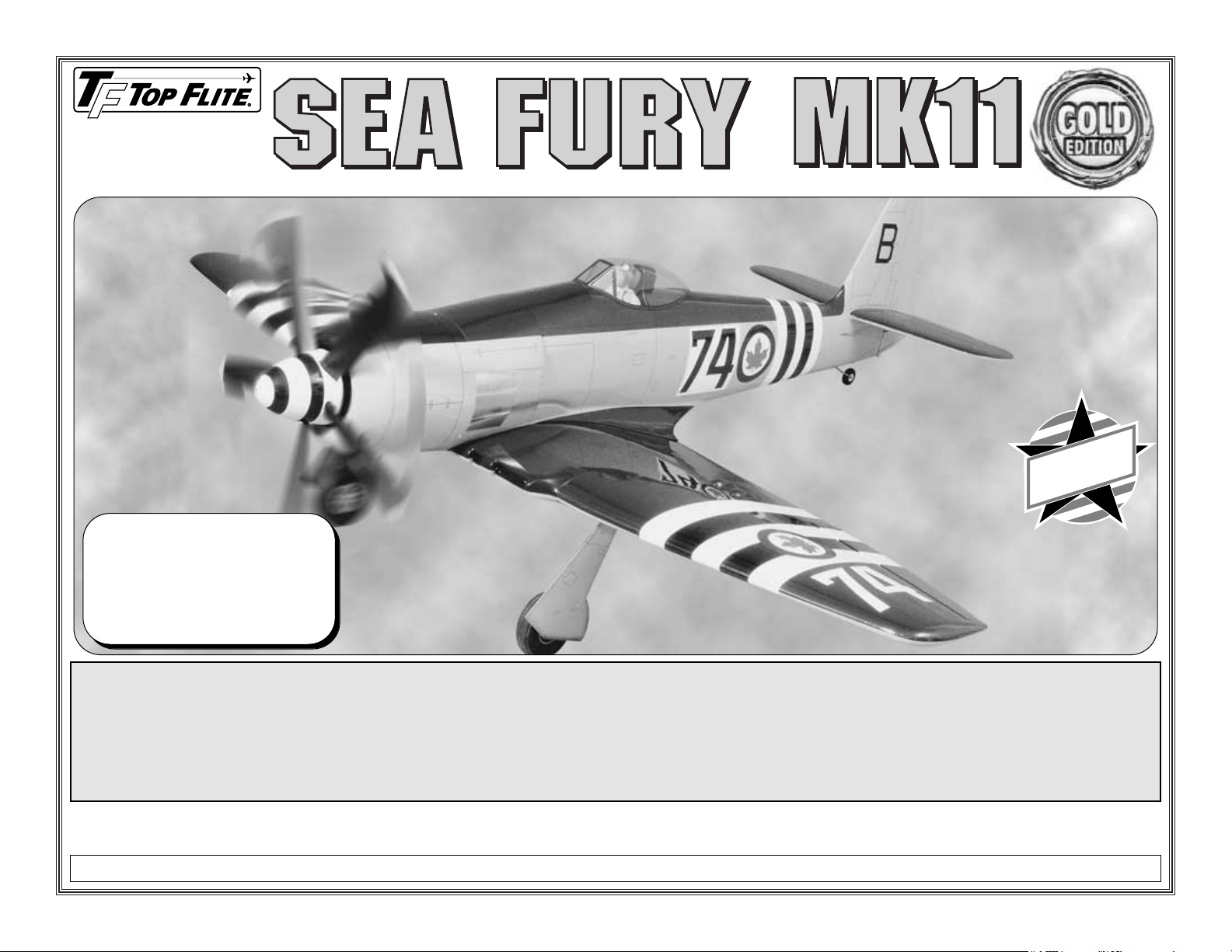
INTRODUCTION
Congratulations and thank you for purchasing the
Top Flite
Gold Edition
Hawker Sea Fury. The Sea
Fury is the type of plane that makes an ideal scale
model no matter what the size (we can’t take all the
credit for a great-flying model!). Because of its large
wing area and long tail moment, you’ll find that the
Sea Fury is stable and predictable in the air.
Additionally, this Top Flite
Gold
kit incorporates
airfoils specially designed for Top Flite’s warbirds
(S8036 at the root and S8037 at the tip). These
airfoils provide slower stall speeds and gentle stall
characteristics making Gold Edition kits among the
friendliest flying warbirds around!
When it comes to construction, the high number of
die-cut parts minimizes carving and fitting, while
complete instructions guide you through every detail.
Without adding any additional scale details you’ll end
up with a model that very much represents a Hawker
Sea Fury. With a little research and some scale
documentation you can go “all-out” and make your
Sea Fury a show-winning model.
1. Your Sea Fury should not be considered as a toy, but
rather a sophisticated, working model that functions very
much like a full-size airplane. Because of its
performance capabilities, the Sea Fury, if not
assembled and operated correctly, could possibly cause
injury to yourself or spectators and damage to property.
PROTECT YOUR MODEL,
YOURSELF & OTHERS
FOLLOW THESE IMPORTANT
SAFETY PRECAUTIONS
- 2 -
Page 3
2. You must assemble the model according to the
instructions. Do not alter or modify the model, as
doing so may result in an unsafe or unflyable model.
In a few cases the instructions may differ slightly
from the photos. In those instances the written
instructions should be considered as correct.
3. You must take time to build straight, true
and strong.
4. You must use an R/C radio system that is in firstclass condition, and a correctly sized engine and
components (fuel tank, wheels, etc.) throughout the
building process.
5. You must correctly install all R/C and other
components so that the model operates properly on
the ground and in the air.
6. You must check the operation of the model before
every flight to insure that all equipment is operating and
that the model has remained structurally sound. Be
sure to check clevises or other connectors often and
replace them if they show any signs of wear or fatigue.
7. If you are not already an experienced R/C pilot,
you should fly the model only with the help of a
competent, experienced R/C pilot.
8. While this kit has been flight tested to exceed
normal use, if the plane will be used for extremely
high stress flying, such as racing, the modeler is
responsible for taking steps to reinforce the high
stress points.
Remember: Take your time and follow the
instructions to end up with a well-built model
that is straight and true.
Before starting to build, compare the parts in this
kit with the Parts List and the die drawings, and
note any missing parts. Also inspect all parts to
make sure they are of acceptable quality. If any
parts are missing, broken or defective, or if you
have any questions about building or flying this
airplane, please call us at (217) 398-8970, or email us at productsupport@greatplanes.com.If
you are contacting us for replacement parts,
please be sure to provide the full kit name (Top
Flite Gold Edition .60 Sea Fury) and the part
numbers as listed in the Parts List.
You can also check our web site at
www.greatplanes.com for the latest updates.
If you have not flown a scale model before, we
recommend that you get the assistance of an
experienced pilot in your R/C club for your first
flights. If you’re not a member of a club, your local
hobby shop has information about clubs in your area
whose membership includes experienced pilots.
In addition to joining an R/C club, we strongly
recommend you join the AMA (Academy of Model
Aeronautics). AMA membership is required to fly at
AMA sanctioned clubs. There are over 2,500 AMA
chartered clubs across the country. Among other
benefits, the AMA provides insurance to its members
who fly at sanctioned sites and events. Additionally,
training programs and instructors are available at
AMA club sites to help you get started the right way.
Contact the AMA at the address or toll-free phone
number below:
Academy of Model Aeronautics
5151 East Memorial Drive
Muncie, IN 47302-9252
Tele. (800) 435-9262
Fax (765) 741-0057
Or via the Internet at: http://www.modelaircraft.org
This is a list of items required to finish the Sea
Fury that must be purchased separately and
require a bit of decision making ahead of time.
Order numbers (in parentheses) are provided for
your convenience.
ENGINE RECOMMENDATIONS
The official engine size recommendation range for
the Sea Fury is .61 to .91 cu. in. [10.0 to 15.0cc]
two-stroke or .91 to 1.2 cu. in. [10.0 to 19.8cc] fourstroke. Our first Sea Fury prototype was flown with
an O.S.®FS-.91 Surpass™II (OSMG0896) which
was more than enough power. Our second
prototype (and the model featured in this
instruction manual and on the kit box
cover–weighing-in at eleven pounds) was flown
with an O.S. .61 FX (OSMG0561). Please take this
advice: The Sea Fury does not need to be
overpowered. Even “all-up” with flaps, retracts,
cockpit kit and pilot, the .61-powered model flew
best at about half to three-quarters throttle and
had plenty of reserve power for scale maneuvers
such as loops, chandelles and steep climb-outs. If
you already happen to have a larger engine, it
could be used in this model (as long as it is within
the size recommendation). But, if you are still
deciding which engine to purchase, a strong .61
two-stroke or a .91 four-stroke is highly
recommended. Flying the Sea Fury with a 1.20
may be within the size recommendation, but an
engine of this size does approach “over-kill,” so
prudent throttle management must be exercised.
Remember, this is a scale model that is intended
to fly in a scale-like manner.
If using a .61 to .75 two-stroke engine, the Top
Flite in-cowl Warbird muffler (TOPQ7915) is
recommended because it may be fully concealed
inside the cowl. The correct header is also
required to connect the
(continued on page 4)
DECISIONS YOU MUST MAKE
NOTE: We, as the kit manufacturer, provide you
with a top quality kit and great instructions, but
ultimately the quality and flyability of your finished
model depends on how you build it; therefore, we
cannot in any way guarantee the performance of
your completed model, and no representations
are expressed or implied as to the performance or
safety of your completed model.
- 3 -
Page 4

(8) #6 x 1/2" mounting screws
(GPMQ3160, pkg. of 8)
JB Weld epoxy
3/4 oz. glass cloth to reinforce the wing
sheeting inside the wheel wells (HCAR5000)
Optional: Robart air filler valve (ROBQ2368)
These items are required if installing Robart
retractable landing gear:
Robart #605HD 90-degree retracts (3/16"
[4.8mm] wire struts) (ROBQ0005)
Robart #188 Air control kit (ROBQ2388)
3/16" x 2" slip-on axles (GPMQ4278)
(2) Robart #190 Quick connectors
(ROBQ2395, pkg. of 2)
4" [102mm] Main wheels (ROBQ1518)
Robart #164G Hand Pump with Gauge
(ROBQ2363)
Servo to operate air control valve
3/4 oz. glass cloth to reinforce the wing
sheeting inside the wheel wells (HCAR5000)
SPINNER
The Sea Fury requires a 4" [102mm] spinner. A P-51shape spinner looks better on this model than a
regular pointed sport spinner. Two C.B. Associates,
Inc. #5105 P-51 spinners (CBAQ5520) were used on
this model. One for static display (
see
page 55) and
one for flying. These spinners include the correct
adapter for the O.S. .61, but another adapter may be
required if using a different engine.
LANDING GEAR OPTIONS
The Sea Fury may be built with either fixed or
retractable landing gear. The pre bent fixed landing
gear wires are included with this kit, so the only
additional item required to build the Sea Fury with
fixed gear is 4" [100mm] wheels. If installing retracts,
there are two recommended options: The kit may be
built to accommodate Robart #605 HD retracts with
3/6" [4.8mm] wire struts (ROBQ0005) or Century Jet
Models #32425 Top Flite Sea Fury system with scale
struts (CJMQ4150). Instructions and are provided for
installation of either gear (see page 18 for additional,
important information on selecting retracts).
If installing the Century Jet Models #3235 Top Flite
System with 1/2" [13mm] diameter struts
(CJMQ4100) or any other system, the landing gear
rail spacing and/or position may require modification
to accommodate the gear.
Both Century Jet systems include all required
components including retracts, struts, air lines,
fittings, air control valve and air tank (some modelers
prefer to replace CJM’s air filler valve with Robart’s
air filler valve).Whichever retract system is installed,
an additional servo will be required to operate the air
control valve.
These items are required if installing Century
Jet Models retractable landing gear:
#32425 Top Flite Sea Fury system with scale
struts (CJMQ4100)
-or#32325 Top Flite Sea Fury system with 1/2"
struts (CJMQ32325)
-andAir pump (may use Robart air pump)
4" [102mm] Main wheels (ROBQ1518)
Servo to operate air control valve
Wheel cover mounts
muffler to the engine. For the O.S. .61 FX or SF
order TOPQ7920. For the Super Tigre®.61 to .75
G-series (muffler bolts go through the engine and
screw into the muffler) order TOPQ7926. For the
Super Tigre .61 to .75 K-series (muffler bolts go
through the muffler and screw into the engine)
order TOPQ7925. Additionally, a long silicone tube
will be required to connect the Top Flite in-cowl
muffler to the header. Aerotrend 3/4" [19.1mm]
inside diameter silicone tubing was used on this
model (AERG2220).
Note: The Top Flite in-cowl muffler is not
recommended for engines over .75 cu in.
Refer to the engine manufacturer’s recommendations
for selecting the correct propellers.
FLAPS
The Sea Fury may be built either with or without
flaps. Flaps are not necessary for an enjoyable
flying experience, but they do add greatly to scale
realism. Landing with flaps is a blast (and can be
safer) because the model is able to fly at reduced
speeds. Full instructions are included for building
the Sea Fury with flaps, but a little extra
craftsmanship and skill (not to mention a little
extra time) will be required.
These additional items are required to build
the Sea Fury with flaps:
(2) Standard servos
(1) Y-connector (HCAM2701– Futaba®)
(1) 6" [150mm] Servo extension (connected to
receiver for field setup (HCAM2000 for Futaba)
(10) Small Pivot Point Hinges
(GPMQ4001, pkg. of 15)
3/32" [2.4mm] brass tube
(for drilling holes for hinges)
- 4 -
Page 5

ADDITIONAL ITEMS REQUIRED
Hardware and Accessories
In addition to the items listed in the “Decisions You
Must Make” section, following is the list of hardware
and accessories required to finish the Sea Fury.
Order numbers are provided in parentheses.
❏ Four to six-channel radio with five to eight servos
❏ (1) Y-connector for ailerons (HCAM2500 – Futaba)
❏ (3) 6" [150mm] Servo extension cords (ailerons - 2,
receiver for aileron - 1 (HCAM2701– Futaba)
❏ Switch/charging jack mount kit (GPMM1000)
❏ 12 oz. Fuel tank (GPMQ4105)
❏ Fuel line (3’, GPMQ4131)
❏ Fuel filler valve for glow fuel (GPMQ4160)
❏ 1" [25mm] Tail wheel (GPMQ4241)
❏ R/C Foam padding (1/4" [6mm], HCAQ1000, or
1/2" [13mm], HCAQ1050)
Adhesives and Building Supplies
In addition to common modeling tools (screw drivers,
hobby knives, drill, etc.), this is the “short list” of the
most important items required to build the Sea Fury.
We
recommend Great Planes Pro™CA and Epoxy glue.
Note: Additional CA may be required, but the quantity
listed below will get you started.
❏ 2 oz. Thin Pro CA (GPMR6003)
❏ 2 oz. Medium Pro CA+ (GPMR6009)
❏ 30-minute epoxy (GPMR6047)
❏ Pro™Wood Glue (GPMR6161)
❏ CA Applicator Tips (HCAR3780)
❏ CA accelerator (GPMR6035)
❏ Lightweight, sandable balsa filler (NHPR2211)
❏ Supply of #11 blades (HCAR0211)
❏ Single-edge razor blades (HCAR0212)
❏ Medium T-pins (HCAR5150)
If you plan to enter the Sea Fury in scale
competition (it’s lots of fun, and the runways are
usually paved!), this kit may be entered in Fun
Scale, Sportsman Scale and Expert Scale classes
in AMA competition. All classes have the same
flight requirements in which you must perform ten
maneuvers, five of which are mandatory. The other
five are up to you–“easy” stuff like a slow, low
inspection pass with flaps extended, or maybe a
touch-and-go. If you have never competed in a
scale contest, you could start out in Fun Scale. In
Fun Scale, the only documentation required is any
proof that a full-size aircraft of this type, in the
paint/markings scheme on your model, did exist. A
single photo, a kit box cover from a plastic model,
or even a painting is sufficient proof! If you’re
interested, contact the AMA for a rule book that
will tell you everything you need to know. You can
find a contest schedule in the back of the AMA
magazine (Model Aviation).
One last note for those who are interested in scale
competition; Strive to build this model to reflect
your documentation. Whatever lines and features
appear on the full size plane should also appear
on the model.
Three-view drawings and photo packs of full size
Sea Furies are available from:
Scale Model Research
3114 Yukon Ave, Costa Mesa, CA 92626
(714) 979-8058
Fax: (714) 979-7279
COCKPIT AND PILOT
Your Sea Fury won’t be complete unless a Top
Flite Sea Fury Cockpit Kit (TOPQ8412) and Top
Flite 1/7 scale WW II Full Body Pilot (TOPQ9000)
are installed. The cockpit kit includes the floor,
side panels, instrument panel, seat, headrest and
accessories. It may be installed after the fuselage
is completed, but is easier to fit during
construction. The Top Flite pilot is the correct size
for this model and fits perfectly in the cockpit.
TRIM SCHEME
The trim scheme on the model on the kit box was
selected from a photo found on the Internet. It’s a
trim scheme of a racing plane, though it has a
military appearance. To duplicate the trim scheme
with MonoKote®, two 6' rolls of dove gray
(TOPQ0211) and one 6' roll of insignia blue
(TOPQ0207) are required. Additionally, a few feet
of black and white MonoKote are required for the
invasion stripes, and Top Flite LustreKote®white
primer (TOPR7801), dove gray (TOPR7211),
insignia blue (TOPR7207) and crystal clear
(TOPR7200) are required for painting (
see
FINISHING beginning on page 56 for full details
on painting and covering).
SCALE COMPETITION
The outline of the Top Flite
Gold Edition
Sea Fury
was derived from three-view drawings, photos and
highly detailed plastic model kits. Some areas of
the outline have been slightly changed to improve
flight characteristics. Notably, the area of the “tail
feathers” has been slightly increased to improve
directional stability and control.
The scale of this model is 1:7 (or 1:7.07 to be
more precise) which was derived by averaging the
scale wingspan and the scale length.
- 5 -
Page 6
❏ Razor Plane (MASR1510)
❏ English size drill bits: 17/64" (or 1/4"), 1/4",
7/32", 3/16", 5/32", 1/8", 7/64", 3/32", 1/16"
-or-
❏ Metric size drill bits: 6.7mm (or 6.4mm), 6.4mm,
5.6mm, 4.8mm, 4mm, 3.2mm, 2.8mm, 2.4mm,
1.6mm
❏ 1/4-20 Tap and #7 [5.1mm] drill for wing bolts
(GPMR8105)
❏ 8-32 Tap and #29 [3.45mm] drill for engine
mounting (GPMR8103)
❏ Denatured or Isopropyl Alcohol (to clean up
excess epoxy)
❏ Sanding tools and assorted sandpaper (
see
Easy-Touch™Bar Sander that follows)
Optional Supplies and Tools
Here is a list of optional tools mentioned in the
manual that will help you build the Sea Fury.
❏ Long handle 9/64" ball end hex wrench
(GPMR8004)
❏ Silver Solder (GPMR8070 w/flux)
❏ Masking Tape (TOPR8018)
❏ Great Planes Plan Protector (GPMR6167) or
wax paper
❏ Dremel®#178 cutting bit (for countersinking
screws in the servo hatch covers)
❏ Robart®Super Stand II (ROBP1402)
❏ Great Planes CG Machine™(GPMR2400)
❏ Top Flite Precision Magnetic Prop Balancer
™
(TOPQ5700)
❏ Straightedge with scale (HCAR0475)
❏ Cutting mat (HCAR0456)
❏ CA Debonder (GPMR6039)
❏ 6-Minute epoxy (GPMR6045)
❏ Milled fiberglass (GPMR6165)
❏ Microballoons (TOPR1090)
❏ R/C-56 Canopy Glue (JOZR5007)
❏ Epoxy brushes (GPMR8060)
❏ Mixing cups (GPMR8056)
❏ Mixing sticks (GPMR8055)
❏ Threadlocker (GPMR6060)
❏ Non-elastic monofilament or Kevlar fishing line
for stab and wing alignment (K+SR4575)
❏ Builders Triangle Set (HCAR0480) (for fin
alignment)
❏ Felt-Tip Marker (TOPQ2510)
❏ Small metal file
❏ Rotary tool such as Dremel
❏ Rotary tool reinforced cut-off wheel
(GPMR8020)
❏ Curved Tip Canopy Scissors for Trimming
Plastic Parts (HCAR0667)
❏ Dead Center™ Engine Mount Hole Locator
(GPMR8130)
❏ Great Planes AccuThrow™Deflection Gauge (for
measuring control throws, GPMR2405)
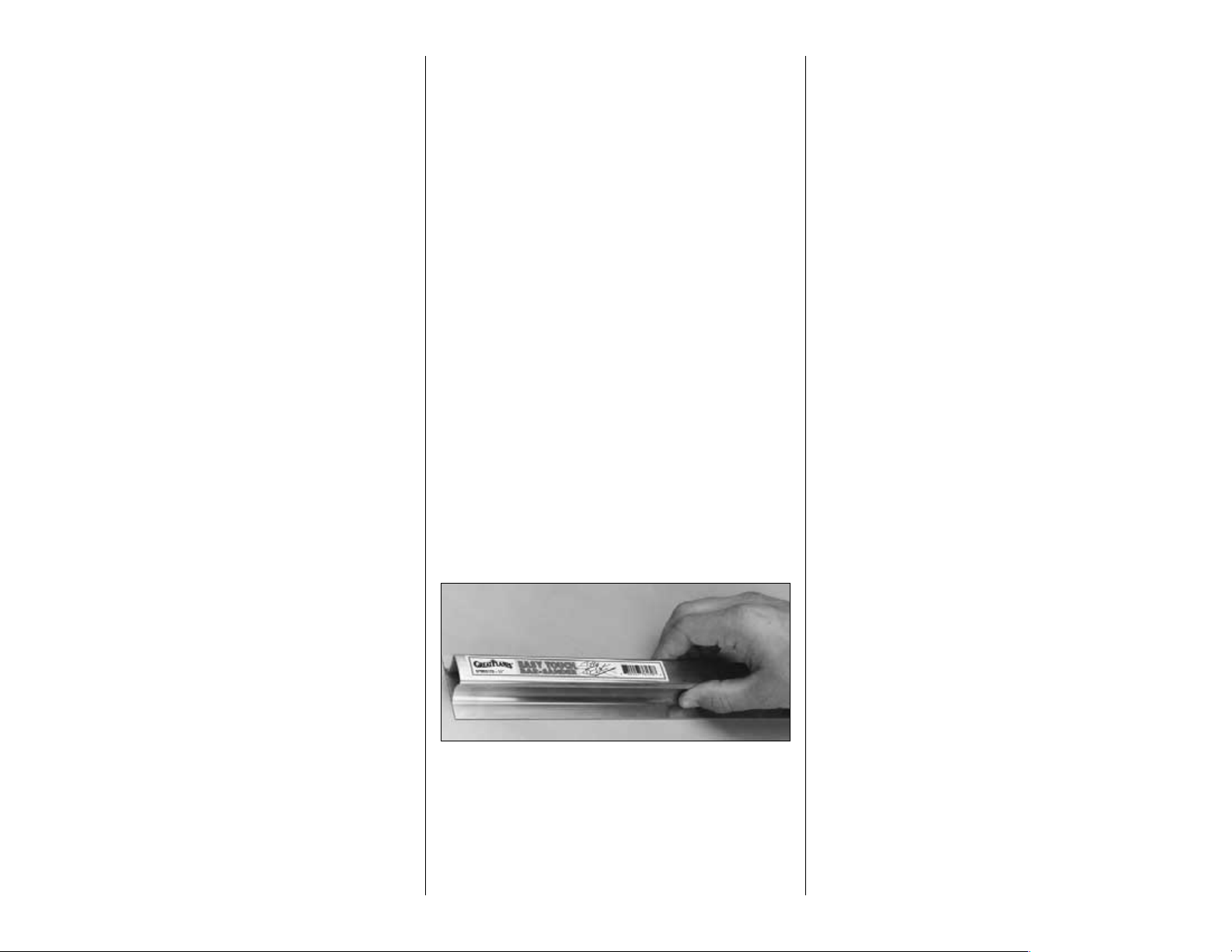
EASY-TOUCH™BAR SANDER
A flat, durable, easy to handle sanding tool is a
necessity for building a well finished model. Great
Planes makes a complete range of Easy-Touch Bar
Sanders (patented) and replaceable Easy-Touch
Adhesive-backed Sandpaper. While building the
Sea Fury, we used two 5-1/2" Bar Sanders and two
11" Bar Sanders equipped with 80-grit and 150-grit
Adhesive-backed Sandpaper.
Here’s the complete list of Easy-Touch Bar Sanders
and Adhesive Backed Sandpaper:
5-1/2" Bar Sander (GPMR6169)
11" Bar Sander (GPMR6170)
22" Bar Sander (GPMR6172)
33" Bar Sander (GPMR6174)
44" Bar Sander (GPMR6176)
11" Contour Multi-Sander (GPMR6190)
12’ roll of Adhesive-backed:
80-grit sandpaper (GPMR6180)
150-grit sandpaper (GPMR6183)
180-grit sandpaper (GPMR6184)
220-grit sandpaper (GPMR6185)
Assortment pack of 5-1/2" strips (GPMR6189)
We also use Top Flite 320-grit (TOPR8030, 4 sheets)
and 400-grit (TOPR8032, 4 sheets) wet-or-dry
sandpaper for finish sanding.
Recommended covering tools
and accessories
❏ Top Flite Heat Gun (TOPR2000)
❏ Top Flite Trim Seal Tool (TOPR2200)
-and-
❏ Top Flite Sealing Iron (TOPR2100)
❏ Top Flite Hot Sock™(TOPR2175)
-or-
❏ 21st Century®Sealing Iron (COVR2700)
❏ 21st Century Cover Sock (COVR2702)
- 6 -
Page 7
IMPORTANT BUILDING NOTES
There are two types of screws used in this kit:
Sheet metal screws are designated by a number
and a length.
For example #6 x 3/4" long [19.1mm]
This is a number six screw that is 3/4" [19.1mm] long.
Machine screws are designated by a number,
threads per inch, and a length.
For example 4-40 x 3/4" long [19.1mm]
This is a number four screw that is 3/4" [19.1mm]
long with forty threads per inch
.
•
When you see the term
test fit
in the instructions,
it means that you should first position the part on
the assembly without using any glue, then
slightly modify or
custom fit
the part as necessary
for the best fit.
•
Whenever the term
glue
is written you should rely
upon your experience to decide what type of glue
to use. When a specific type of adhesive works
best for that step, the instructions will tell you what
glue is recommended.
•
Whenever just
epoxy
is specified you may use
either
30-minute epoxy or6-minute epoxy. When
30-minute epoxy is specified, it is highly
recommended that you use only 30-minute (or
45-minute) epoxy because you will need the
working time and/or the additional strength.
•
Photos and sketches are placed before the
step they refer to. Frequently you can study photos in
following steps to get another view of the same parts.
TYPES OF WOOD
BALSA BASSWOOD PLYWOOD
PREPARE TO BUILD
1. A set of miniaturized building plans is included in
the middle of this manual. They may be removed and
used as a quick, handy reference, so you don’t have
to get out the full-size plans when you are not
building over them.
2. If you’ve already purchased the retractable
landing gear, or as soon as you do, take the air lines
out of the package. Unravel the lines and hang them
somewhere in your shop. When it’s time to install the
retracts, the kinks will be out of the lines and they’ll
be easier to work with.
(Continued on page 10)
1/64" = .4mm
1/32" = .8mm
1/16" = 1.6mm
3/32" = 2.4mm
1/8" = 3.2mm
5/32" = 4mm
3/16" = 4.8mm
1/4" = 6.4mm
3/8" = 9.5mm
1/2" = 12.7mm
5/8" = 15.9mm
3/4" = 19mm
1" = 25.4mm
2" = 50.8mm
3" = 76.2mm
6" = 152.4mm
12" = 304.8mm
15" = 381mm
18" = 457.2mm
21" = 533.4mm
24" = 609.6mm
30" = 762mm
36" = 914.4mm
METRIC CONVERSION
1" = 25.4mm (conversion factor)
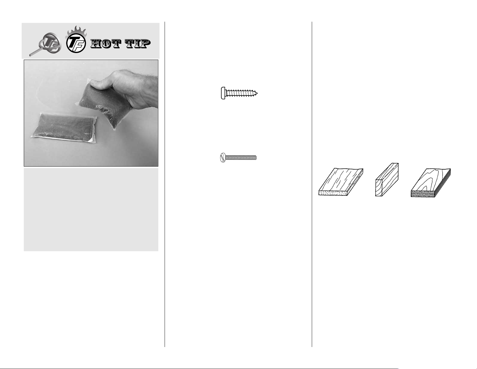
Plastic bags filled with lead shot are recommended
to be used as building weights because they
assume the shape of curved surfaces and apply
uniform pressure without making dents in balsa.
Shot can be purchased at sporting goods stores
where hunting supplies are sold. #6 shot is
recommended. One 25 lb. bag costs about fifteen to
twenty dollars. Small, sealable food storage bags
can be used to hold the shot. Tape the bags shut for
security. Each bag holds about two to three pounds.
Fifteen to twenty bags is adequate for this project.
- 7 -
Page 8
- 8 -
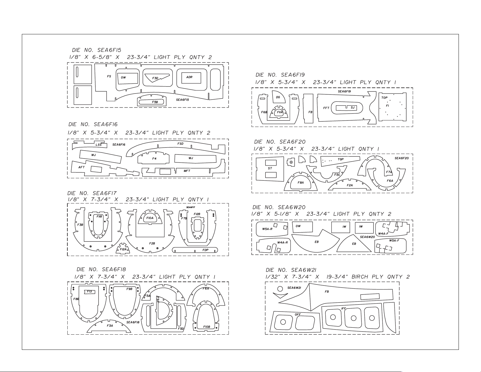
PLY DIE-CUT PATTERNS
Page 9
- 9 -
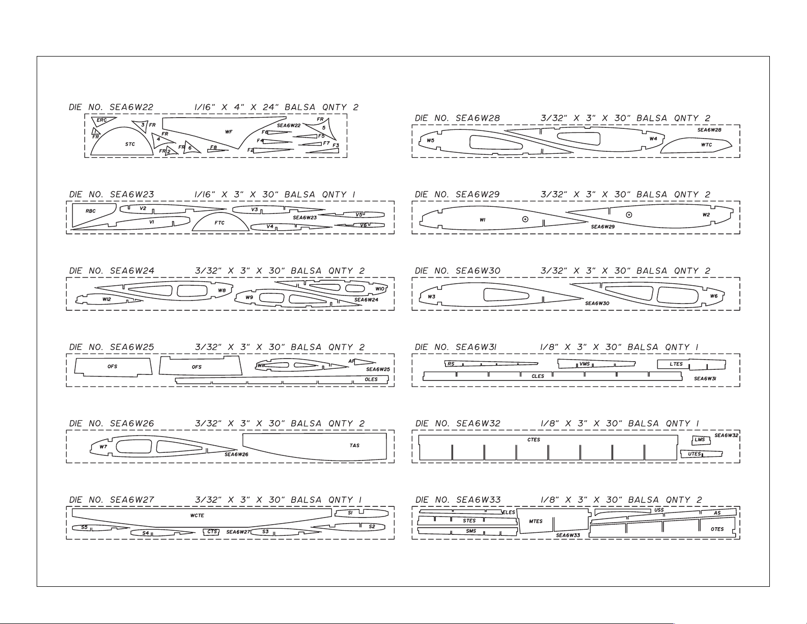
BALSA DIE-CUT PATTERNS
Page 10
3. Remove all the parts from the box. Use a ballpoint
pen (not a felt tip pen) to lightly write the name or
size on each piece so it can be identified it later. Use
the
die-cut patterns
on pages 8 & 9 to identify and
mark the die-cut parts before removing them from
their die sheets. Many of the parts already have
numbers stamped on them, but in some cases the
numbers are located alongside the parts or only on
the die drawings in the manual. If a part is difficult to
remove from its die sheet, don’t force it out. Instead,
cut around the part with a hobby knife and a #11
blade. After removing the parts from their die sheets,
lightly sand the edges to remove slivers or diecutting irregularities. As you proceed, it’s not
necessary to save every scrap of wood, but some of
the larger pieces of wood should be saved.
Note: If building the wing with fixed landing gear, do
not punch out the holes in ribs W4 and W5 for the
retractable landing gear rails.
4. Separate the parts into groups such as stab, fin,
wing, and fuse. Store smaller parts in zipper-top
food storage bags.
BUILD THE TAIL SURFACES
Make the stab and fin skins
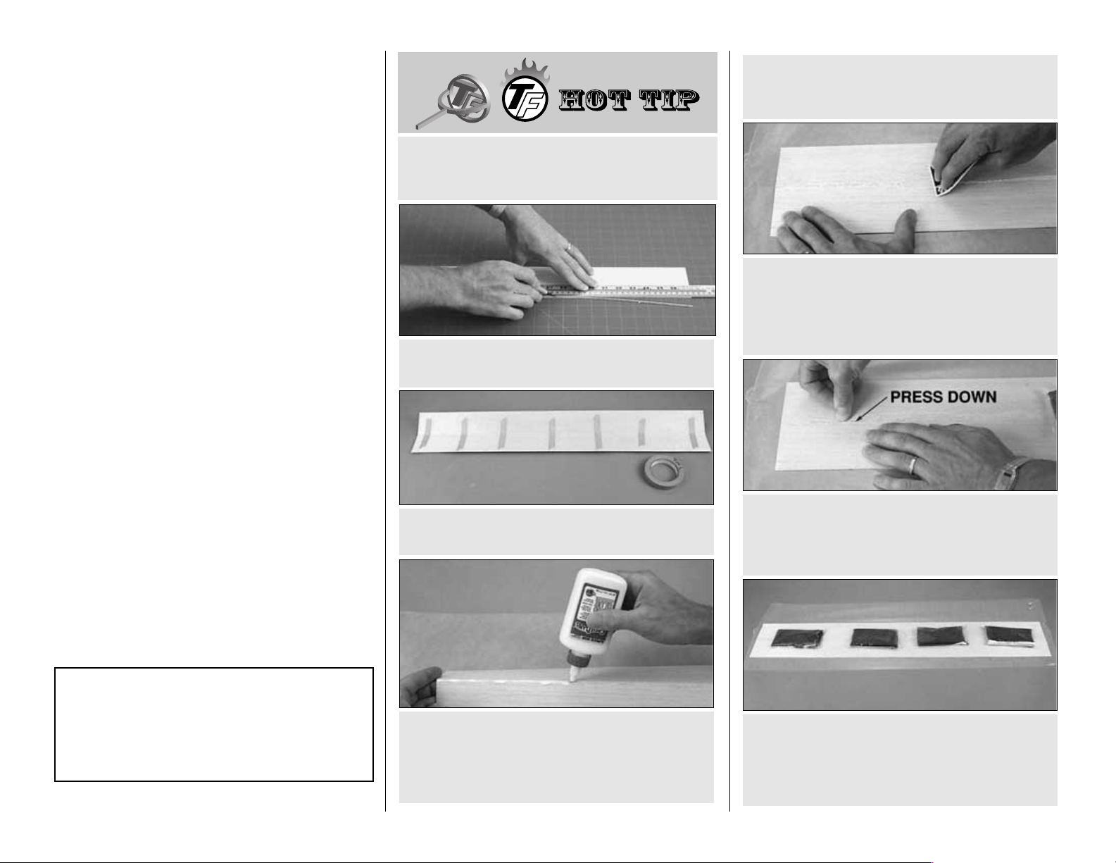
❏ 1. Use the
Hot Tip
that follows or your own method
to make three 1/16" x 6" x 30" [1.6 x 152 x 762mm]
balsa sheets from six 1/16" x 3" x 30" [1.6 x 76 x
762mm] balsa sheets.
F. Place weights on top of the sheet to hold it flat
while the glue dries.
G. After the glue dries, remove the tape and
sand the sheets flat and even.
E. Press the joining edges of the sheets down to
make sure they are even. This is important and will
greatly minimize the amount of sanding required
(and thus prevent over-thinning the balsa).
D. Lay the sheets on your workbench covered
with Great Planes Plan Protector or wax paper.
Use a credit card or something similar as a
squeegee to simultaneously press the sheets flat
as you wipe the glue from the seam.
enough working time to get the sheets aligned.
Hardened CA is also much harder than balsa which
can make sanding difficult.
C. Turn the sheets over and apply slow drying glue
such as Great Planes
Pro
aliphatic resin
(GPMR6160) to the joining edges. Some modelers
prefer to use CA for gluing sheeting together, but
CA is not recommended because it does not allow
B. Use masking tape to tightly tape the trued
edges of the sheets together.
A. Use a straightedge to true one edge of two
balsa sheets.
HOW TO GLUE
BALSA SHEETING TOGETHER
Top Flite selects balsa that is intended for sheeting,
though occasionally a few of these sheets may have
a small nick or split near the ends. If your kit contains
a few of these sheets, arrange them and glue them
together so the defects will not interfere with the final
shape of the skin.
- 10 -
Page 11
❏ 2. Set the sheets aside until it’s time to sheet the
tail surfaces.
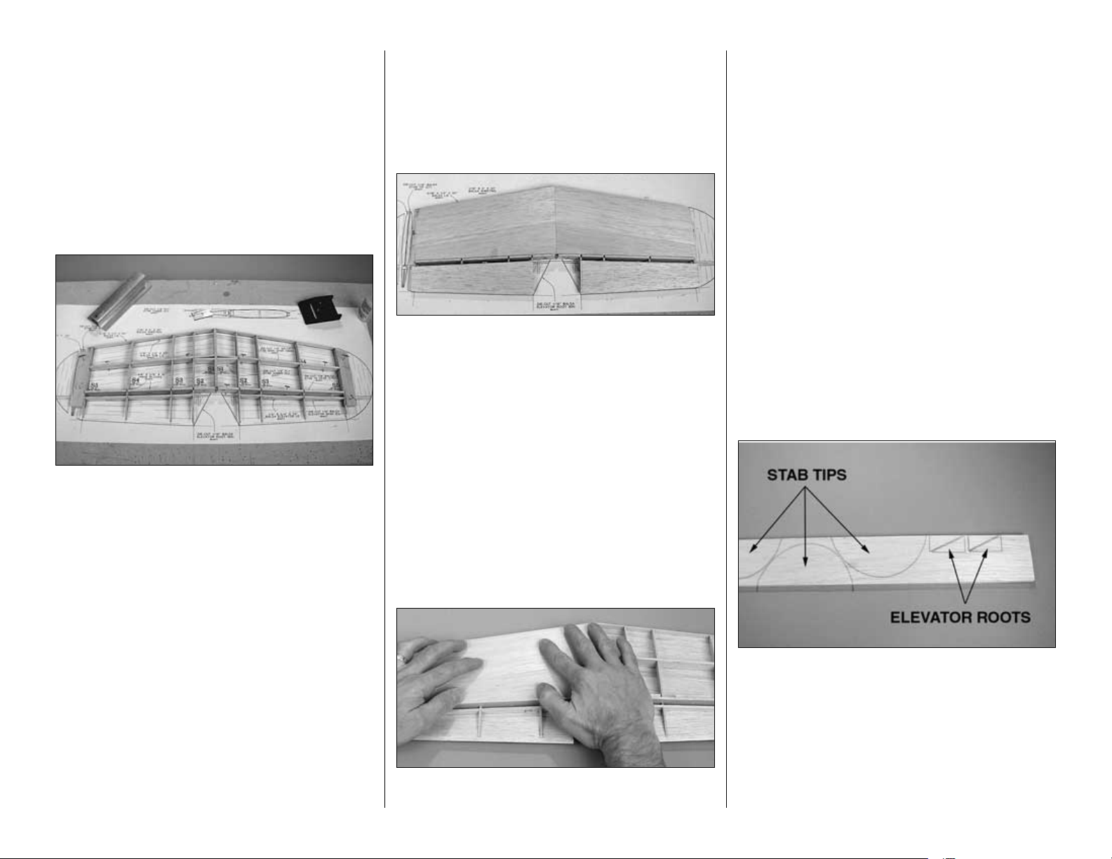
Build the fin and rudder
❏ 1. Unroll the fuse plan sheet. Roll it inside out so
it will lie flat.
❏ 2. Position the fuse plan so the fin and rudder
are over your flat building board, or cut the fin and
rudder from the plan. Cover the plan with Great
Planes Plan Protector or wax paper so glue will not
adhere to the plan.
IMPORTANT BUILDING NOTE:
The fin is initially built and sheeted while lying on its
right side supported by the TE spars and ribs.
When it’s time to sheet the other side, the fin is turned
over and supported by the sheeting and TE spar on the
left side. The TE spars will be trimmed even with the
sheeting after the fin has been completed.
The stab and wing panels are built the same way, thus
simplifying construction and ensuring straight and true
flying surfaces (providing your workbench is flat). This
system also eliminates the requirement for jig tabs on
the ribs which can break off while removing the ribs
from the die sheets, or during construction.
❏ 3. Without using glue, join the die-cut 1/16"
[1.6mm] balsa fin ribs V 1 through V6 to the die-cut
1/8" [3.2mm] balsa vertical main spar (VMS), the
lower main spar (LMS), the upper TE spar (UTES),
the lower TE spars (LTES) and the rudder spar
(RS). Add the die-cut 3/32" [2.4mm] balsa fin center
TE spar (CTS). Use T-pins to hold the assembly to
the plan.
❏ 4. Making certain that the vertical main spar, the
upper and lower TE spars and the ribs are contacting
the plan at their lowest point, use medium CA to glue
all the parts of the assembly together. Be certain to
pull the rudder spar all the way up into the notches of
the ribs when gluing it into position. Note: Use only
a small amount of CA on each glue joint. Avoid using
excess CA which will cause glue blobs that may
interfere with the sheeting that will be added later.
The Sea Fury was designed and built by Hawker
Aircraft Ltd., Sutton Lane, Langley, Bucks, England.
Note: Some modelers tend to sand the sheeting
too much after it is applied to the structure,
making low spots over supported areas (such as
over ribs and stringers) where fingers can easily
punch through. By following the procedure above
(specifically, by aligning the joining edges of the
sheets as shown in step E), little sanding should
be required. Most of the sanding that isrequired
should be done before the sheeting is glued in
place. The only sanding that should be required
after the sheeting is glued to the structure is final
sanding with 320-or 400-grit sandpaper.
Here are a few other things to keep in mind
while sanding balsa sheeting:
1. Sand the sheets on a flat work surface
free from hardened drops of glue or other
imperfections that will damage the sheeting.
2. Sand the sheeting only as much as
required. The inside needs to be sanded just
enough to remove excess glue and doesn’t have
to be smooth.
3. Though sanding
across
the grain
removes material faster, it leaves visible
scratches. Sanding
with
the grain is preferable,
especially when finish-sanding.
4. If the glue joint is uneven and requires
much sanding, it may be best to leave it slightly
uneven rather than over-sanding. A slightly uneven
glue joint is preferable to paper-thin balsa!
-11-
Page 12
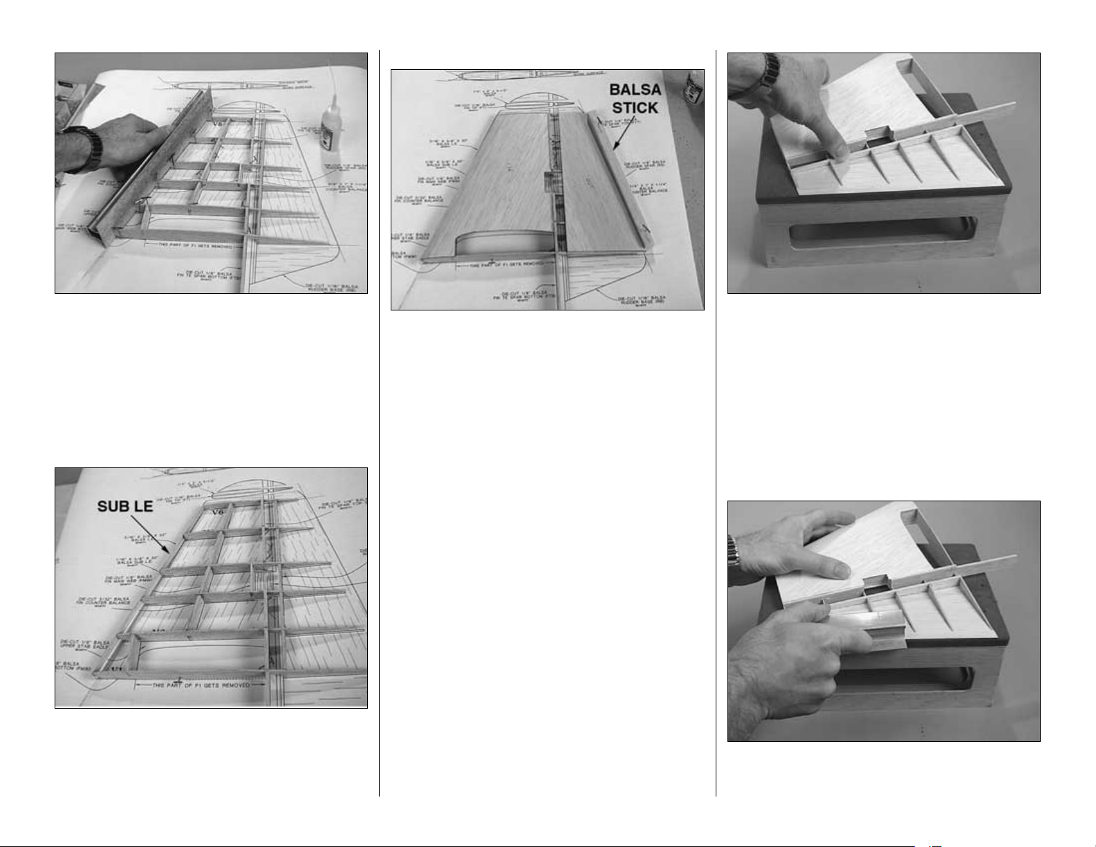
❏ 5. Use a bar sander with 80-grit sandpaper to
sand the front the fin ribs at an angle for the sub LE.
❏ 6. Cut the 1/16" x 1/2" x 30" [1.6 x 12.7 x 762mm]
balsa sub LE to the correct length, then glue it to the
front of the fin ribs. Save the remainder for the stab
sub LE’s. Sand the upward facing edge of the sub LE
even with the tops of the ribs.
Refer to this photo for the following two steps.
❏ 7. Remove any T-pins that will interfere with the fin
and rudder skins or that will be concealed beneath
the skins after they are glued in place. Using the fin
assembly as a guide, make a fin skin for the left side
of the fin from one of the balsa sheets you prepared
earlier. Be certain to make the skin slightly oversized
as it will be trimmed to exact shape later. Glue the
skin into position with thick CA or aliphatic resin.
❏ 8. Make a rudder skin the same way. Glue the
rudder skin into position. Hint: Pin a large balsa stick
to the building board aligned with the location of the
rudder TE on the plan. This will insure accurate
positioning of the skin.
❏ 9. Remove the assembly from the building board.
Sand the right side of the fin so the sub LE and spars
are even with the ribs.
❏ 10. Use the second balsa sheet you prepared to
make another fin and rudder skin. Place the sheeted
side of the fin/rudder assembly on the building
board. Glue the remaining fin skin only to the right
side of the fin.
❏ 11. Place the fin on your workbench or a platform
so the TE of the rudder is even with the edge.
❏ 12. Use a bar sander with 80-grit sandpaper to
sand the TE of the rudder to a fine point as shown in
the cross-section of the plan.
-12-
Page 13
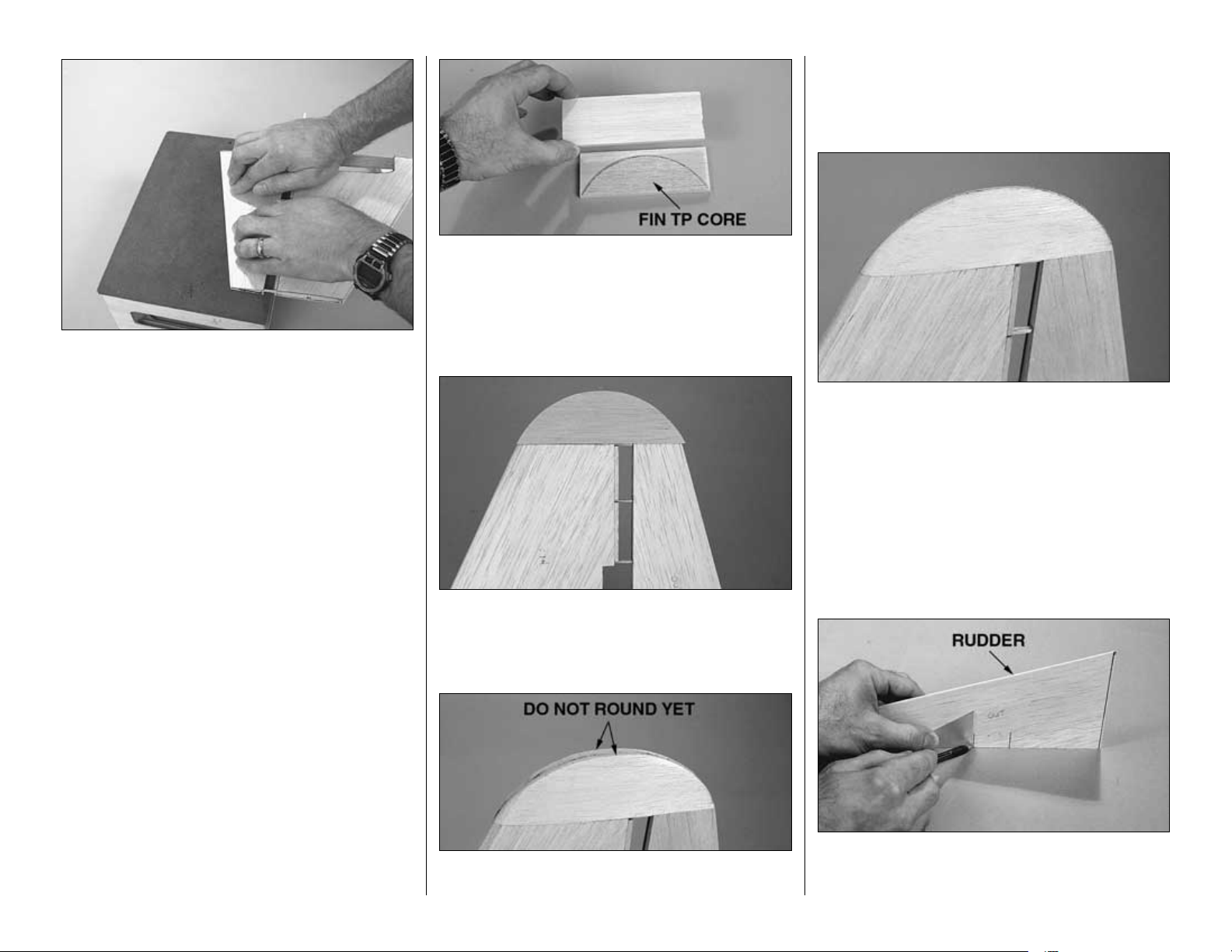
❏ 13. Glue the remaining rudder skin to the rudder.
When doing so, position the rudder so it is resting flat
on the workbench.
❏ 14. Glue both die-cut 1/8" [3.2mm] balsa upper
stab saddles (USS) to the inside of the rudder
skins and rib V2 as shown on the plan. Trim the fin
skins even with the saddles and the lower main spar.
❏ 15. Use a bar sander with 80-grit sandpaper to
true the edges of the sheeting even with the sub LE
and rib V6. Sand the edges of the upper and lower
TE spar even with the fin sheeting.
❏ 16. Cut the fin LE from the 3/16" x 1/2" x 30" [4.8
x 12.7 x 762mm] balsa stick, then glue it to the fin.
Save the remainder of the balsa stick for the stab LE.
❏ 17. Sand both ends of the fin LE even with the top
and bottom of the fin. Use a razor plane followed with
progressively finer grits of sandpaper to round the fin
LE as shown in the cross-section on the plan.
❏ 18. Cut two 5-1/2" [140mm] pieces from the 1/4 x
2" x 11-7/8" [6.4 x 51 x 302mm] balsa sheet. Glue
the die-cut 1/16" [1.6mm] balsa fin tip core (FTC)
between both 1/4" [6.4mm] balsa sheets with the
bottom edges aligned. Sand both 1/4" [6.4mm] outer
pieces even with the fin tip core.
❏ 19. Test fit the tip to the fin/rudder. Be certain the
tip is vertical and in alignment with both the fin and
rudder. If necessary make adjustments, then glue
the tip into position.
❏ 20. Use a razor plane followed by a bar sander to
shape the tip even with the fin and rudder sheeting,
but do not round yet. Hint: While sanding, rest the
bar sander on the sheeting, but apply pressure only
to the tip. If you fear sanding the sheeting too much,
protect it with a few strips of masking tape.
❏ 21. Finish shaping the tip by rounding and
smoothing. For scale appearance, note that the tip is
sanded rather thin, yet round.
Finish the fin and rudder
❏ 1. Separate the rudder from the fin by using a razor
saw to cut through the ribs and the tip. Use a bar sander
with 80-grit sandpaper to sand the remainder of the ribs
even with the fin TE and rudder spar.
❏ 2. Use a small square and a ballpoint pen to mark
the rudder where the counter balance is to be glued
on later (between ribs 3 & 4).
-13-
Page 14
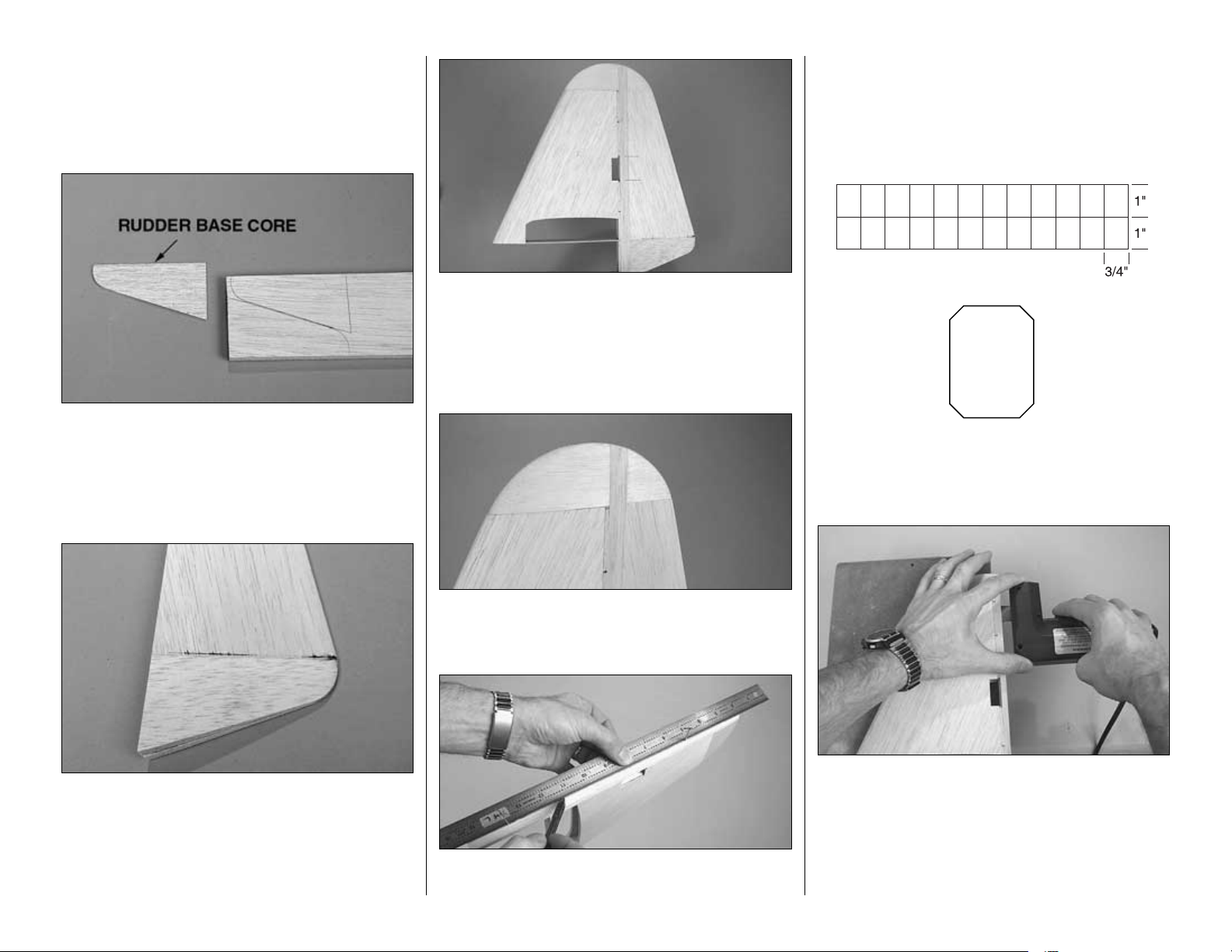
❏ 3. Sand the bottom of the rudder sheeting even
with the bottom rudder rib.
❏ 4. Trace the die-cut 1/16" [1.6mm] balsa rudder
base core (RBC) onto one end of the 3/8" x 3" x 30"
[9.5 x 76 x 762mm] balsa sheet two times as shown.
❏ 5. Cut both pieces from the 3/8" [9.5mm] balsa
sheet and glue one on each side of the base core.
Glue the assembly to the bottom of the rudder.
Shape the rudder base to match the rudder, but do
not round until instructed to do so (after the fuse has
been constructed).
❏ 6. Cut the fin TE and the rudder LE from a 1/4"
x 3/4" x 30" [6.4 x 19.1 x 762mm] balsa stick and
glue them to the fin and rudder. Sand the fin TE even
with the fin and sand the rudder LE even with the
rudder. Temporarily tack-glue the rudder to the fin
with about five small drops of medium CA.
❏ 7. Final-sand the fin TE and rudder LE and the fin
and rudder tip even with each other. Break the
rudder free from the fin.
❏ 8. Mark a centerline on the trailing edge of the fin.
This can most accurately be done by sticking two
T-pins in the center of the TE–one near each end.
Position a straightedge against the T-pins and draw a
line with a ballpoint pen. Mark a centerline on the LE
of the rudder the same way.
❏ 9. Cut four 3/4" x 1" [19 x 25mm] hinges from the
2" x 9" [51 x 230mm] CA hinge strip supplied with
this kit. Snip the corners off so they go in easier.
❏ 10. Using the centerlines as a guide, cut the hinge
slots where shown on the plan with a Great Planes
Slot Machine, then proceed to step 11. If you do not
have a Slot Machine, follow the procedure that
follows to cut hinge slots with a hobby knife and a
#11 blade
(or run to the hobby shop and buy a
Slot Machine!).
-14-
Page 15
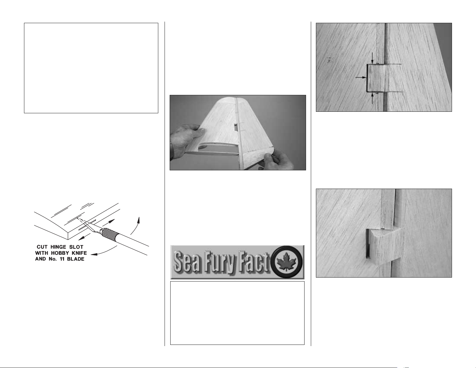
How to cut hinge slots with a hobby knife
When using a hobby knife to cut hinge slots, one of
the most common mistakes made by modelers is
making the slots too tight. This restricts the flow of
CA to the back of the hinges. Another mistake made
when installing hinges is not using enough glue to
fully secure the hinge over its entire surface area.
This results in hinges that are only
tack glued
. Follow
these steps to cut hinge slots with a hobby knife:
A. Using the centerline as a guide, cut one of the
hinge slots in the fin or rudder where shown on the
plan with a #11 blade. Begin by cutting a shallow slit.
Make three or four cuts along the same line, going
slightly deeper each time. As you proceed, be
certain to go straight into the wood and move the
knife from side to side until the blade has reached
the correct depth for the hinge.
B. Test fit a hinge into the slot. If the hinge does not
slide into the slot easily, remove the hinge and
reinsert the knife working the blade back and forth a
few times to provide more clearance (it’s the back
edge of the blade that does the widening).
C. Cut the rest of the hinge slots the same way.
❏ 11. Temporarily join the rudder to the fin with the
hinges. If necessary, sand the fin and rudder so they
match up
well.
❏ 12. Use a razor plane followed by a bar sander to
shape the LE of the rudder to a “V” for control throw.
Make certain 1-5/8" [41mm] of right and left rudder
throw can be achieved. Increase the angle of the “V”
if necessary.
Hey, now all that has to be done on the rudder is
make the counter balance...
❏ 13. True the edges of the fin sheeting around the
cut-out for the counter balance where indicated by
the arrows in the photo. Notch the LE of the rudder
to accommodate the 3/4" x 1" x 1-1/4" [19.1 x 25.4 x
32mm] balsa counter balance where it will align
with the cut-out in the fin. Test fit the counter balance
into the notch and see how it matches up to the cutout in the fin. Make adjustments where necessary.
❏ 14. Securely glue the counter balance to the
rudder. Sand the counter balance to match the
rudder, then round the leading edge just enough to
clear the fin.
❏ 15. Fill the small notches in the upper and lower
TE spars on the left side of the fin with lightweight
balsa filler. Allow to dry, then final-sand.
Full-Size Sea Fury Specifications:
Wingspan: 38'4" [11.7m]
Wing area: 280 sq ft [260 sq m]
Overall length (from tip of spinner to end of
rudder): 34'7" [10.5m]
Stab span: 14' [4.3m]
Max. gross weight: 14,600 lbs [6,623kg]
Normal weight: 12,316 lbs [5,587kg]
NOTES ABOUT CA HINGES
This kit is supplied with CA hinge material
consisting of a 3-layer lamination of mylar and
polyester specially made for hinging model
airplanes. When properly installed, this type of
CA hinge provides the best combination of
strength, durability and easy installation. We use
these hinges on all our Gold Edition warbirds, but
it is essential to install them correctly. Follow
the hinging instructions in this manual for the
best result. The techniques shown have been
developed to ensure thorough and secure gluing.
-15-
Page 16
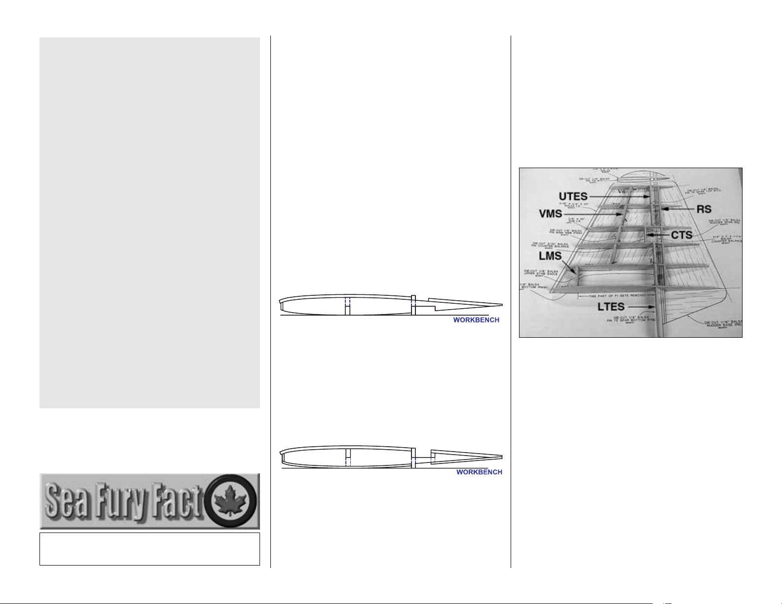
Build the stab and elevators
Note: The stabilizer is built upside-down. There is
nothing to remember or figure out ahead of time.
Simply build the stab as instructed.
❏ 1. Roll the wing plan inside out so it will lie flat.
Cut the stab plan from the wing plan and place it over
your flat building board. Cover the plan with Plan
Protector so glue will not adhere.
Refer to this photo for the following four steps.
❏ 2. Without using glue, join both sets of die-cut
3/32" [2.4mm] stab ribs S2 through S5 to both die-
cut 1/8" [3.2mm] balsa stab main spars (SMS).
Place the assembly over the stab plan. If necessary,
widen the notches in the ribs and spars so they fit at
the angle on the plan.
❏ 3. Still without glue, join both die-cut 1/8" [3.2mm]
balsa stab TE spars (STES) and both die-cut 1/8"
[3.2mm] balsa elevator spars (ELES) to the ribs,
then pin the assembly to the building board aligned
over the plan. Glue the ribs to the main and TE spars.
Hint: Pin a large balsa stick to the building board at
both ends of the stab to help hold the two halves
together and maintain alignment.
❏ 4. Glue both die-cut 3/32" [2.4mm] balsa stab
ribs S1 together. Test fit, then use epoxy to glue the
die-cut 1/8" [3.2mm] plywood stab joiner (SJ) and
the S1’s to the assembly.
❏ 5. The same as was done on the fin, sand the
fronts of the ribs at an angle to match the sub LE.
Use the remainder of the 1/16" x 1/2" [1.6 x 12.7mm]
balsa stick used for the fin sub LE to make the stab
sub LE, then glue it into position. Sand the top of the
sub LE and spars even with the ribs.
❏ 6. Remove or relocate any T-pins that will interfere
with the sheeting or that will be concealed under the
sheeting after it's glued into place. Cut the top stab
and elevator skins from the second balsa sheet
prepared earlier. Glue the skins to the top of the stab
and elevators.
❏ 7. Remove the assembly from the plan. Use a
ballpoint pen to mark the side of the stab you just
sheeted as “bottom”.
❏ 8. Cut the hinge blocks from the 1/4" x 3/8" x 11-
7/8" [6.4 x 9.5 x 302mm] balsa stick, then glue them
to the stab TE spars where shown on the plan. Trim
the top of any hinge blocks where necessary so they
do not interfere with the top stab sheeting.
❏ 9. Cut the top stab and elevator skins from the
remainder of the balsa sheeting. With the stab lying
flat on the workbench, glue one of the stab skins into
position. When doing so, press down to hold the
sheeting to the structure and to hold the structure to
the flat work surface. Glue the other stab skin to the
stab the same way.
❏ 10. The same as was done on the rudder skin,
sand the TE of the bottom elevator skins to match
the tapering angle of the ribs. Glue the top elevator
skins into position.
❏ 11. True all the sheeting even with both ends of
the stab/elevators and the sub LE.
❏ 12. Cut the remainder of the 3/16" x 1/2" [4.8 x
12.7mm] balsa stick used for the fin LE into two pieces
for the stab LE, then glue it into position. Shape the LE
even with the stab, but do not round yet.
❏ 13. Place both die-cut 1/16" [1.6mm] balsa stab
tip cores (STC) over the plan. Note which end is the
front (they’re not symmetrical like the fin tip, but
they’re close). The same as you did for the fin tip, use
one of the stab tip cores to lay out the patterns on the
remainder of the 3/8" x 3" x 30" [9.5 x 76 x 762mm]
balsa sheet used for the rudder base. While you’re at
it, lay out the die-cut 1/16" [1.6mm] balsa elevator
root core (ERC) patterns as well.
-16-
Page 17
❏ 14. Cut the tips and roots from the balsa sheet.
Glue them to the die-cut cores. Glue the stab tips to
both ends of the stab and elevators and shape them
the same way you did the fin (in two stages: first
sanding the tips to match the stab and elevator, then
by rounding the tips).
Finish the stab and elevators
❏ 1. Use a ballpoint pen to mark the elevators in an
inconspicuous location as “L” and “R.” Cut the
elevators from the stab. Sand the tips and rib stubs
even with the elevators and stab.
❏ 2. Glue the elevator root blocks to the elevator.
Sand the fronts of the blocks even with the LE spars.
Cut the elevator leading edges from the 1/4" x 3/4"
x 30" [6.4 x 19.1 x 762mm] balsa stick, then glue
them to the elevators.
❏ 3. Shape the elevator LE’s and the root blocks
even with the elevators.
❏ 4. Cut the hinge slots. Shape elevator leading edges
to a “V” to achieve 5/8" [16mm] of control throw.
❏ 5. With the elevators temporarily joined to the stab
with the hinges, center the elevator joiner wire on
the elevators as shown on the plan. Use a ballpoint
pen to mark the location of the joiner wires on
the elevators.
❏ 6. Drill a 1/8" [3.2mm] hole in both elevators for
the joiner wire.
❏ 7. Cut a groove in both elevators to accommodate
the joiner wire. Hint: Use a Great Planes
Groove
Tube
(GPMR8140) or a 1/8" [3.2mm] brass tube
sharpened on one end to cut the grooves.
❏ 8. Test fit the elevators to the stab with the joiner
wire. If necessary, bend the wire so the elevators
align with each other. Note: If you found it necessary
to bend the wire, note that it must be reinserted into
the elevators the same way when it’s time to glue it
in. If this is the case, file a small notch in the right
side of the joiner near the end.
❏ 9. Round the elevator root blocks.
-17-
Page 18
BUILD THE WING
Make the wing skins
❏ 1. The same as the balsa sheets for the tail
surfaces were made, make five 6" x 24" [152 x
610mm] sheets, and four 9" x 24" [229 x 610mm]
sheets from 22 3/32" x 3" x 24" [2.4 x 76 x 610mm]
balsa sheets.
❏ 2. After all the glue has dried, make two 12" x 24"
[305 x 610mm] sheets from four 6" x 24" [152 x
610mm] sheets (there will still be one 6" x 24" [152 x
610mm] sheet remaining).
Prepare the landing gear ribs
Retract options:
If building the Sea Fury with Robart #605 HD retracts
with 3/16" [4.8mm] wire struts, there are two options.
The “long-strut” option represents the correct scale
length of the landing gear struts. However, because of
poor ground handling over rough grass fields caused by
the unusually long length of the struts, the long-strut
option is recommended only if flying from smooth,
paved surfaces. If flying from grass fields, the “shortstrut” option is recommended due to improved ground
handling. If installing any one of the Century Jet Models
retract options recommended, due to their design and
rigidity, the struts may be left at the scale length no
matter what surface you are flying from. Note: Most of
the instructions depict the installation of the Robart
gear, but apply to both the installation of Robart gear
and the CJM scale gear. Where necessary, separate
instructions and photos are provided for the installation
of the CJM scale gear.
❏ 1. Place the center section of the wing plan.
Follow the instructions to prepare the landing gear
ribs for the right side of the center section first.
Perform this step only if installing #32425 CJM
Top Flite Sea Fury system with scale struts.
❏❏R2. Use a hobby knife to cut out one set of die-
cut 1/8" [3.2mm] plywood rib doublers W4A-F and
W5A-F along the embossed lines as shown in the
sketch. Do not cut out the areas indicated by the
dashed lines, as these are for the fixed landing gear rail.
❏❏4. Use 30-minute epoxy to glue the rib doublers
to a die-cut 3/32" [2.4mm] balsa wing rib W4 and W5
as shown on the plan and in the photo. Note: If
installing Robart #605 retracts, glue die-cut 1/8"
[3.2mm] plywood rib doublers W4A-R and W5A-R
to the ribs. If this is your first time through, be certain
to make the ribs for the right side of the center
section by gluing the doublers to the correct side of
the ribs (the ribs shown in the photo are for the
right side).
❏❏F3. Use a hobby knife to cut out one set of die-
cut 1/8" [3.2mm] plywood rib doublers W4A-F and
W5A-F along the embossed lines as shown in the
sketch. Do not cut out the areas indicated by the
dashed lines, as these are for the retractable landing
gear rails.
W5A-F
W4A-F
FIXED LANDING GEAR OPTION
DO NOT CUT OUT
Perform this step only if installing fixed
landing gear.
Note: Steps preceded by an “F” are intended for
fixed landing gear only (and will also be shaded).
Steps preceded by an “R” are intended for
retracts only.
-18-
FIXED LANDING GEAR OPTION
W4A-F
DO NOT CUT OUT
5A-F
W
Page 19
❏❏5. Cut out the balsa from the ribs within the
open area of the ply doublers to accommodate the
landing gear rails.
❏ 6. Repeat the procedure, but this time, make a set
of landing gear ribs for the left side of the center section
being certain to glue the doublers to the correct sides
of the ribs as indicated on the wing plan.
Frame the center section
❏ 1. If building flaps, use a straightedge and a
hobby knife to cut partway through one side of diecut 3/32" [2.4mm] balsa wing ribs W3, W4, W5, W6,
W7 & W8 from the top of the notch to the tip as
shown. Later, the bottom of the ribs will be removed
to accommodate the flaps.
Refer to this photo for the following six steps.
❏ 2. Cut two 1/8" x 3/8" x 36" [3.2 x 9.5 x 914mm]
basswood sticks and two 3/16" x 3/8" x 24" [4.8 x 9.5
x 610mm] balsa sticks to a length of 23-13/16"
[604.8mm]. Make a top and bottom center main
spar by gluing a basswood stick to the balsa stick.
Save the leftover basswood for the outer panels.
❏ 3. Without using any glue until instructed to
do so, join ribs W1 through W5 to the die-cut 1/8"
[3.2mm] balsa center TE spar (CTES). Fit one of the
center main spars prepared earlier to the notches in
the bottom of the ribs. The balsa side of the center
main spar faces downward.
❏ 4. Join the die-cut 1/8" [3.2mm] plywood forward
dowel plate (FDP) to ribs W1 & W2.
❏ 5. Position the assembly over the plan. Pin the
center TE spar and the ribs over their locations on
the plan. Hint: Instead of directly pinning the ribs and
center TE spar to the plan, an easier and more
secure method is to place 1/2" x 1/2" [13 x 13mm] (or
similar size) balsa sticks (indicated by the small
arrows in the photo) on both sides of the ribs and
center TE spar and pin the sticks to the plan.
❏ 6. Make
shims
from leftover balsa to support
bottom center main spar and push it up into the
notches in the ribs. Be certain the low-point on the
bottom of the ribs is contacting the plan. The exact
thickness of the shims may vary from kit to kit, but
the approximate thickness will be 1/8" [3.2mm].
❏ 7. Making certain the bottom of the ribs and the aft
TE are fully contacting the plan, and that the ribs are
pushed all the way down into the notches of the
center TE spar, glue the ribs to the center TE spar. Pull
the bottom center main spar tightly up into the notches
in the ribs; then, making sure the bottom of the ribs are
contacting the plan, glue the spar to the ribs.
❏ 8. Glue the top center main spar into position with
the balsa side up. Use a small square to make
certain the W5 ribs on both ends of the center
section are vertical.
-19-
Page 20
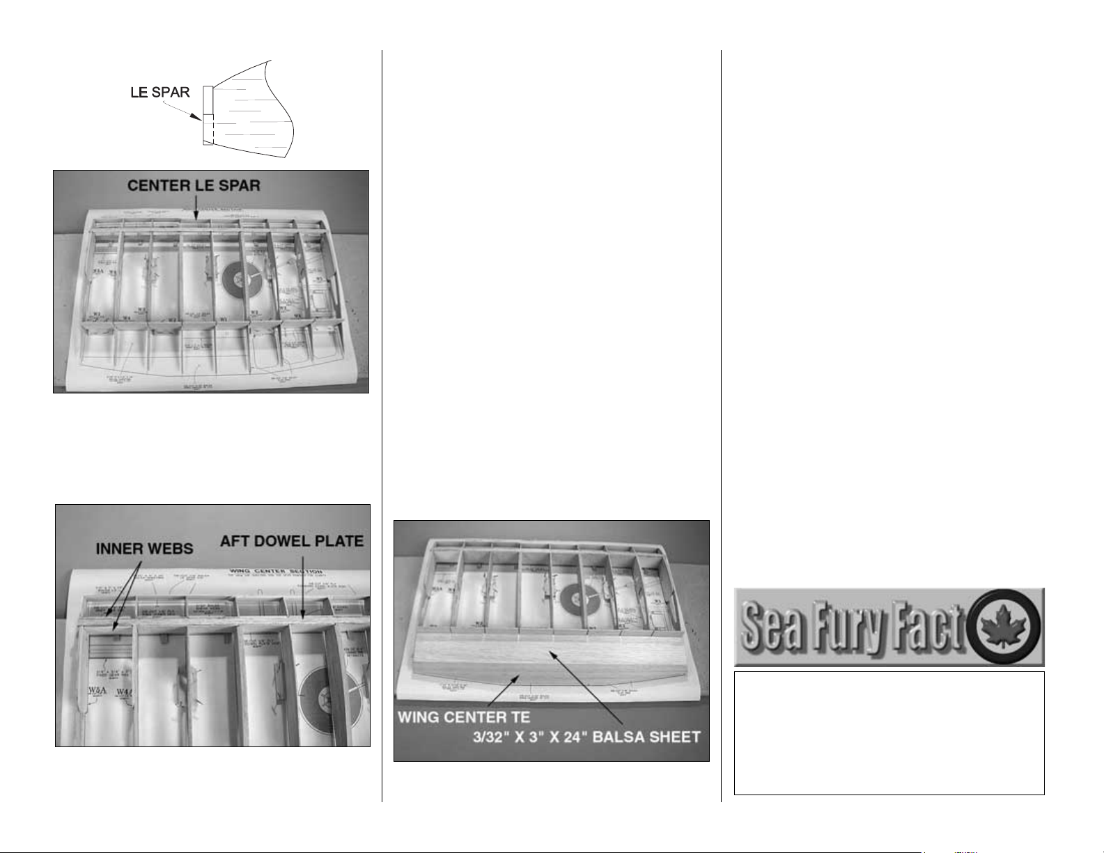
❏ 9. Test fit, then glue the die-cut 1/8" [3.2mm] balsa
wing center LE spar (CLES) to the assembly. Be
certain the center LE spar is centered vertically on all
the ribs.
Refer to this photo for the following three steps.
❏ 10. Glue both die-cut 1/8" [3.2mm] plywood aft
dowel plates (ADR) to the top and bottom spars
between ribs W1 and W2.
❏ 11. Of the 3/32" x 3" x 36" [2.4 x 76 x 914mm]
balsa sheets included with this kit, one of them is
hard and the rest are soft. Locate the hard balsa
sheet. Cut the ten shear webs for the center section
from the sheet, then glue them into position. Save
the remainder of this sheet for the shear webs for the
outer panels.
❏ 12. Use epoxy to glue four die-cut 1/8" [3.2mm]
plywood inner webs (IW) to both the front and back
of the main spars on both ends of the center section.
Be certain to use enough epoxy for a secure bond,
but don’t use too much epoxy so as to interfere with
the fit of the wing joiners that will be added later.
❏ 13. Sand the top center main spar, the center LE
spar and the webs even with the top of the ribs.
❏ 14. Glue the die-cut 3/32" [2.4mm] balsa center
TE (WCTE) to a 3/32" x 3" x 24" [2.4 x 76 x 610mm]
balsa sheet. From now on this will be referred to as
the top TE sheet.
❏ 15. Remove or relocate any T-pins that may
become concealed after the top sheeting is glued
into position. If using weights to hold the sheeting
down, all the T-pins may be removed.
❏ 16. Sand the top TE sheet flat and even.Test fit and
trim the sheet to fit the top of the wing against the
center TE making sure it aligns with the TE indicated
on the plan. Glue the top TE sheet into position.
❏ 17. Glue one of the 3/32" x 12" x 24" [2.4 x 305 x
610mm] balsa sheets prepared earlier to the top of
the center section. The suggested method is to apply
aliphatic resin to the top of all the ribs and spars and
to the aft edge of the sheet where it contacts the
center TE spar. Position the sheet and use weights to
hold it down. Use medium CA to glue the front of the
sheet to the top of the center LE spar. Allow the
aliphatic resin to dry before proceeding.
❏ 18. Remove the center section from the building
board. Note: Do not trim the bottom of the center TE
spar from the bottom of the wing until instructed to
do so.The center TE spar supports the section when
joining the outer panels.
If building the wing with fixed landing gear,
proceed to “Mount the fixed landing gear” on
page 22.
The Sea Fury uses a Bristol Centaurus 18 cylinder,
twin row, radial, air-cooled, supercharged engine.
Max. power is 2,300 H.P. in full supercharger mode
at maximum engine power altitude.
Engine oil tank capacity is 14 gallons with oil cooler.
Exhaust pipe configuration in sliding grill provides
thrust augmentation.
-20-
Page 21
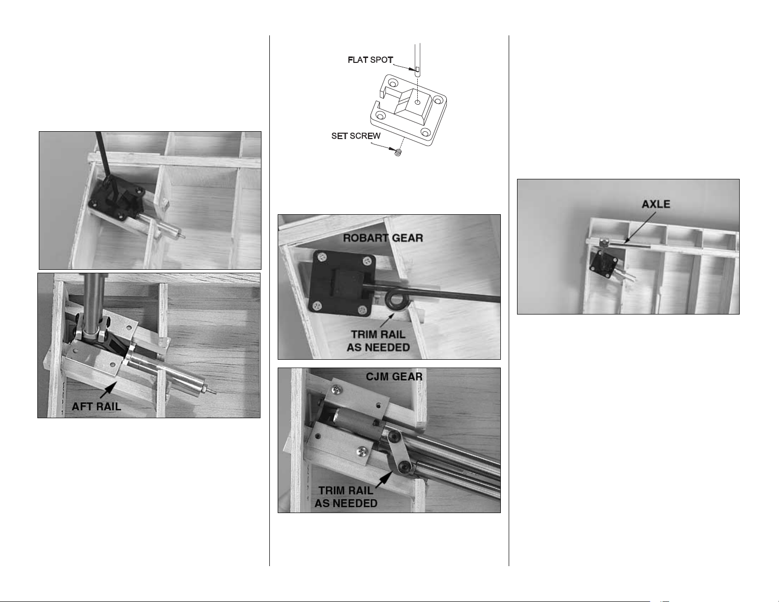
Mount the retracts
❏❏
R1. Cut two 3-5/8" [92mm] long retract rails
from the 3/8" x 1/2" x 24" [9.5 x 12.7 x 610mm]
maple stick (if installing the scale CJM retracts, cut
three rails and glue two of them together to make a
3/4" x 1/2" x 3-5/8" [19.1 x 12.7 x 92mm] aft rail).
❏❏R2. Test fit the rails into the openings in the ribs
on the right side of the center section. If necessary,
bevel the openings to accommodate the rails. Test fit
one of the retracts between the rails to make certain
it fits. Make adjustments if necessary.
❏❏R3. Securely glue the retract rails into position
with 30-minute epoxy. For additional strength, add
Great Planes Pro Milled Fiberglass (GPMR6165). Hint:
The outer ends of the rails are to be sanded at an angle
flush with the end of the center section. It may be easier
to do this before gluing the rails into position.
❏❏R4. If installing Robart gear, file a flat spot on
the end of the wire strut near the top for the set
screw in the retract unit to lock onto. Mount the strut
into the retract units and tighten the set screw.
❏❏R5. Position the retract unit between the rails.
Mark the locations for the holes for the mounting
screws. Drill appropriate size holes in the rails for the
screws. If using #6 screws, drill 7/64" [2.8mm] holes.
Use a rotary tool with a sanding drum to trim the aft
rail to accommodate the coil in the strut.
Perform steps 6 & 7 only if installing the Robart gear.
❏❏R6. Cut the right landing gear strut to the correct
length. (For the long-strut option, the scale distance
from the wheel axle to the pivot point is 8" [203mm]. For
the “short-strut” option, the distance from the wheel axle
to the pivot point is 6" [152mm].)
❏❏R7. File a flat spot on the end of the strut for
the set screw in the axle (not included, GPMQ4278).
The flat spots must be positioned so the axles will be
parallel with the main spars (as shown in the photo)
when the set screw in the axle is tightened.
Perform this step only if installing CJM scale
retracts.
❏❏R8. Position the landing gear strut in the landing
gear cam (the cast aluminum part of the gear that
pivots to extend and retract the gear) so the axle is
parallel with the bottom main spar (though the photo in
the preceding step is of the Robart gear, the same idea
is illustrated). Tighten the set screw in the cam to lock
the strut in this position. Note: Before the gear doors
are mounted to the struts in step R10 on page 25, the
struts must be permanently glued into the cams with
JB Weld (epoxy specially formulated for bonding metal).
-21-
Page 22

❏❏R9. Mount a 4" [102mm] wheel (not included) to
the axle with a 3/16" [4.8mm] wheel collar on both
sides. (Only one collar is required for CJM gear.)
Retract the wheels into the wing. Cut the ribs as
necessary to accommodate the wheels. Be certain the
retracts are able to fully lock in the retracted position.
❏ R10. Return to step two and mount the other
retract the same way.
❏ R11. For the best appearance and durability, use
30-minute epoxy or finishing resin to apply 3/4 oz.
glass cloth (HCAR5000) to the inside surface of the
top sheeting between the ribs of the wheel wells.
This will fuelproof and strengthen the exposed
sheeting inside the wing.
❏ R12. Sand the bottom main spar and center LE
spar even with the bottom of the ribs. Glue pieces of
leftover balsa to the landing gear rails to support the
bottom sheeting after it is cut out for the retracts.
❏ R13. Paint the wheel area inside the wing with
fuelproof paint. Best results will be achieved with an
airbrush. If you are using a paint that only comes in a
spray can (such as Top Flite LustreKote) and wish to
use an airbrush, spray the paint through a tube into a
cup. Allow LustreKote to stabilize in the cup for about an
hour. Transfer the paint to the spray jar for airbrushing.
When finished mounting the retracts, proceed to
“Sheet the bottom of the center section” on the
next page.
Mount the fixed landing gear
❏ F1. Use 30-minute epoxy to glue both 3/4" x
3/4" x 4" [19.1 x 19.1 x 102mm] grooved
basswood fixed landing gear rails into the
notches in ribs W4 & W5. After the epoxy hardens
use another batch of 30-minute epoxy to glue
both 3/4" x 3/4" x 7/8" [19.1 x 19.1 x 22.2mm]
maple torque blocks to the rails and the ply
doublers where shown on the plan. Note:
Although the balsa shear webs and ply inner
webs do not appear in the photo, they should
already be installed in your model.
❏ F2. Drill 3/16" [4.8mm] holes through the rails
and the torque blocks where shown on the plan
for the fixed landing gear wires. Chamfer the
opening of the holes to accommodate the gear,
then test fit the gear.
Refer to this photo for the following
three steps.
-22-
Page 23

Sheet the bottom of the center section
❏ 1. Cut a hole through the top sheeting where
shown on the plan for the servo wires and retract
gear air lines.
Refer to this photo for the following two steps.
❏ 2. If building flaps, cut the hatch supports from the
1/8" x 1/2" x 30" [3.2 x 12.7 x 762mm] basswood stick,
then glue them into position where shown. Sand the
hatch supports even with the bottom of the ribs.
❏ 3. Cut the flap hinge blocks that go in the wing from
the 3/8" x 3/8" x 30" [9.5 x 9.5 x 762mm] balsa stick.
Glue the flap hinge blocks into position where shown on
the plan. Be certain the hinge blocks align with the
bottom of the ribs as shown in the cross-section.
❏ 4. Cut both wing bolt blocks to fit between ribs
W1 and W2 from the 3/4" x 1" x 6" [19.1 x 25.4 x
152mm] balsa stick. Glue the wing bolt blocks to the
center TE spar and the ribs.
❏ 5. Sand the wing bolt blocks even with the bottom
of the ribs. Only between the W2 ribs, bevel the
trailing edge of the top TE sheet to the same angle
as the ribs. Hint: Use a piece of leftover plywood as
a “fence” to keep from sanding past the #2 ribs.
❏ 6. Lay the wing upside-down on your flat
workbench resting on the top sheeting and the
center TE spar. Sheet the bottom of the wing with the
3/32" x 12" x 24" [2.4 x 305 x 610mm] balsa sheet
prepared earlier. If building the wing with fixed gear,
first cut slots in the sheeting to accommodate the
landing gear rails as shown in the photo. The same
as when sheeting the top of the wing, it is
recommended that aliphatic resin be used, except
for gluing the sheeting to the LE spar where medium
CA is best. Do not glue the sheeting to the servo
hatch supports. This will facilitate trimming the
sheeting when fitting the hatches later.
❏ 7. Sheet the bottom of the wing over the wing bolt
blocks between the W2 ribs and the center TE spar
using a portion of the 3/32" x 6" x 24" [2.4 x 152 x
610mm] balsa sheet prepared earlier. Save the
remainder of this sheet for the inner flaps (or inner
flap sheeting if not building flaps). After sheeting the
wing, do not trim the bottom of the center TE spar
until instructed to do so (after the outer panels are
joined to the center section).
❏ 8. Use a long bar sander with 80-grit sandpaper
to sand the top and bottom sheeting even with both
ends of the center section and the center LE spar.
Glue the 1/4" x 1" x 24" [6.4 x 25.4 x 610mm] balsa
leading edge to the sheeting and LE spar. Trim the
LE even with the sheeting and both ends of the
center section, but do not final-shape until instructed
to do so.
The Sea Fury was designed and built by Hawker
Aircraft Ltd., Sutton Lane, Langley, Bucks, England.
❏ F3. Drill 1/16" [1.6mm] holes through the
landing gear rails for the #2 x 1/2" [12.7mm]
screws for the nylon landing gear straps.
Temporarily secure the gear to the rails with the
screws and straps.
Note: Mount the molded ABS wheel covers to the
landing gear wires as shown on page xxxx for the
retractable landing gear wires.
-23-
Page 24

❏ 9. If not building flaps, sheet the bottom of the
wing from the center TE spar aft using the remainder
of the 3/32" x 6" x 24" [2.4 x 152 x 610mm] balsa
sheet used to sheet between the W2 ribs.
If not building flaps, proceed to “Fit the retracts.”
Build the inner flaps
Build the right flap first so your progress will
match the photos.
❏❏1. Cut and remove the lower portions of ribs
W3, W4 & W5 along the lines partially cut earlier.
Make half-ribs that fit between the wing ribs from
leftover 3/32" [2.4mm] balsa. Glue the half-ribs into
position. Sand the half ribs and the trimmed-down
wing ribs even and sand the trailing edge of the wing
sheeting on top of the wing down to a thickness of
1/32". (Though bottom of the wing in the photo is not
sheeted, yours should be at this time.)
Refer to this photo for the following two steps.
❏❏2. Use one of the die-cut 1/32" [.8mm] plywood
inner flap frames (IFF) as a pattern to make a flap
skin from the remainder of the 3/32" x 6" x 24" [2.4 x
152 x 610mm] balsa sheeting used for the bottom of
the wing.
❏❏3. Cut the flap LE from the 1/4" x 1/2" x 36" [6.4
x 12.7 x 914mm] balsa stick and glue it to the top of
the flap skin (save the remainder of the stick for the
left inner flap and for the outer flaps). Glue the diecut 1/16" [1.6mm] balsa flap ribs F2 through F5 to
the flap skin and the flap LE.
❏❏4. Cut the hinge blocks that go into the flaps
from the 3/8" x 3/8" x 30" [9.5 x 9.5 x 762mm] balsa
stick leftover from the hinge blocks for the wing. Glue
the hinge blocks to the flap. Use a bar sander with
80-grit sandpaper to sand the flap LE even with the
tops of the flap ribs and bevel the TE of the flap skin
to the same angle as the flap ribs.
❏❏5. Glue the inner flap frame to the top of the
flap. Test fit the flap to the wing. Sand the flap as
necessary for a good fit.
❏ 6. Build the left inner flap the same way.
If not installing retracts, proceed to “Mount the
flap servos.”
Fit the retracts
❏❏
R1. Cut a small hole in the bottom sheeting
between the retract rails.
❏❏R2. Carefully enlarge the hole until the retract
rails and balsa supports can be seen.
-24-
Page 25

❏❏R3. Neatly enlarge the opening just enough to
fit the retract. Mount the retract to the rails. Hint: For
a neat appearance, round the corners of the wing
sheeting as in the photo.
❏❏R4. A little at a time, cut the opening in the
bottom sheeting for the wheel and strut until the gear
is able to fully retract into the wing. Be certain there
is enough clearance on the aft edge of the opening
to allow the gear to retract even if slightly bent back
during a rough landing. Usually at least 1/4" [6mm]
clearance is suggested. (There is a photo of the
installed CJM gear on page 26.)
❏ R5. Use curved plastic scissors to cut out the
molded ABS left wheel cover. If building the wing
with short struts, trim the wheel covers to fit the
struts. (One of the wheel covers can be seen in
following photos.)
Steps R6 through R9 are for the Robart gear. If
installing CJM gear, go to step R10.
❏❏R6. Make two 1-1/8" [28.6mm] long wheel
cover mounting blocks from the 1/4" x 3/8" x 6"
[6.4 x 9.5 x 152mm] basswood stick. Drill 1/16"
[1.6mm] holes through the mounting blocks, then
mount them to the strut with the nylon straps and #2
x 3/8" [9.5mm] screws. The top block should be
about 1" [25mm] below the top of the wheel cover
and the bottom block should be about 1" [25mm]
above the bottom of the wheel cover. (The upper
mounting block is shown in the photo.)
❏❏R7. Trim the mounting blocks to the correct
thickness, so that when the wheel cover is attached
to the blocks (by gluing with CA later on), the wheel
covers will contact the bottom of the wing when the
wheels are retracted. On the model shown in this
manual, the upper mounting block required
additional balsa to build it up to the correct thickness.
Note: The thickness of the lower blocks depends
upon how far inside the wing the landing gear wire is
when the gear is retracted. If necessary, remove the
landing gear wire and bend it in a vice until the
required thickness of the lower block is
approximately 1/4" [6mm].
❏❏R8. Trim the bottom wing sheeting as necessary
to accommodate the upper mounting block.
❏❏R9. Thoroughly sand the wheel cover so glue
will adhere. Glue the wheel cover to the mounting
blocks with medium CA.
Propeller:
Hydraulically operated, constant speed, left-hand
rotating, tractor Rotol propeller. 12' 9" [3.99m]
diameter, five duralumin blades with pitch from
29 degrees to 64 degrees.
-25-
Page 26

Perform steps R10 and R11 only if installing
CJM gear.
❏❏R10. At this time the struts must be
permanently glued into the cams with JB Weld metal
bonding epoxy. Position two plastic landing gear door
mounts (included with the CJM Top Flite Sea Fury
scale gear) on the strut so the outer door mounting
surface of the mounts is parallel with the bottom of
the wing when the gear is retracted. Use thin CA to
glue the door mounts to the struts. If necessary, glue
strips of hard balsa to the mounts, then align with the
bottom surface of the wing by sanding flush so the
gear doors will fit the bottom of the wing when the
landing gear is retracted. As can be seen in the
photo, only the top mount on this model required
building up with balsa.
❏❏R11. Use a ballpoint pen and a straightedge to
mark alignment lines on the bottom of the wing across
the gear door mounts. Position the gear door on the
bottom of the wing, then drill 1/16" holes through the
doors and mounts. Mount the gear doors to the door
mounts using #2 x 3/8" [9.5mm] screws included with
this kit. Glue a strip of leftover 1/8" [3.2mm] balsa to the
inside of the gear door to add rigidity.
❏❏R12. Connect the air lines to the air cylinder on the
retract. Use a retract air pump or a can of compressed
air such as Hobbico
®
Duster,™(HCAR5500) to retract
and extend the gear. Check the fit of the wheel cover to
the wing when the wheel is retracted and fully locked.
Make adjustments to the height and positioning of the
mounting blocks so the wheel covers fit well.
❏❏R13. Optional: Cut two 2-1/4" x 5-1/2" [57 x
140mm] sheets from a 1/32" [.8mm] plywood sheet
(not included). Place one of the sheets in one-half of
the opening in the wing for the wheel and draw the
outline of the cutout onto the ply sheet. Do the same
for the other ply sheets in the other side of the wheel
opening. Cut the sheets along the line, then glue
them to the bottom sheeting inside the wing. This
greatly strengthens the wing sheeting around the
edges of the wheel opening.
❏ R14. Return to step 1 and mount the other retract
the same way.
If not building flaps, proceed to “Build the outer
wing panels.”
Mount the flap servos
❏❏
1. Cut a hole in the bottom sheeting along the
inside edges of the hatch supports.
-26-
Page 27

❏❏2. Drill 1/16" [1.6mm] holes in two 5/16" x 3/4"
x 7/8" [7.9 x 19.1 x 22.2mm] basswood servo mount
blocks and mount the aileron servo to the blocks
using the screws that came with the servo. Glue the
servo mount blocks to a die-cut 1/8" [3.2mm]
plywood servo hatch with 30-minute epoxy (be
certain the servo is positioned on the hatch as
shown on the plan for the side of the center section
you are working on, and that the servo arm is
centered in the opening in the hatch). Note: The
basswood servo mount blocks are porous and
rapidly absorb epoxy. Apply a few coats of epoxy to
the blocks and wait a few minutes between coats to
let it soak in before mating the blocks to the hatch.
❏❏3. After the epoxy has hardened, remove the
screws that mount the servos to the blocks. Apply a
few drops of thin CA to the holes and allow to
harden. Remount the servo to the blocks.
❏❏4. Place the hatch (with the servo) over the
hatch supports on the wing. Securely holding the
hatch in position, drill six 1/16" [1.6mm] holes
through the punchmarks in the hatch and the hatch
supports. Without moving the hatch, use a ballpoint
pen to draw the outline of the hatch directly onto the
sheeting. Remove the hatch.
❏❏5. Enlarge the holes in the hatch only with a
3/32" [2.4mm] drill. Countersink the holes in the
hatch for the #2 x 3/8" [9.5mm] flathead hatch
mounting screws. Hint: Use a Dremel #178 cutting
bit to countersink the holes.
❏❏6. Add a few drops of thin CA to the holes in the
hatch supports for the hatch mounting screws and
allow to fully harden. Mount the hatch with the screws.
❏ 7. Return to step one and mount the other flap
hatch the same way. Make certain the hatches are
positioned as shown on the wing plan.
This is all that can be done on the center section
until the outer panels are completed and joined.
Build the outer wing panels
❏
1. Build the left outer panel first. Cut the left wing
panel plan from the wing plan and place it over your
flat building board. Cover the plan with Plan
Protector so glue will not adhere.
❏❏2. Make two spar doublers as shown on the
plan from the two 1/8" x 3/8" [3.2 x 9.5mm]
basswood sticks leftover from the center section.
Glue each spar doubler to a 3/16" x 3/8" x 24" [4.8 x
9.5 x 610mm] balsa stick as shown in the photo, to
make the top and bottom outer main spars. Cut
the spars to a length of 19-3/4" [502mm].
Refer to this photo for the following seven steps.
❏❏3. Using care, widen the notches in one set of
die-cut 3/32" [2.4mm] balsa wing ribs W6 through
-27-
Page 28

W12 and in the die-cut 1/8" [3.2mm] balsa mid TE
spar (MTES), the outer TE spar (OTES) and the
aileron spar (AS) so they can be joined together at
the angle shown on the plan.
❏❏4. Join the ribs to the mid TE spar, outer TE
spar and the aileron spar. Fit one of the outer main
spars into the notches in the bottom of the ribs. Place
the assembly over the plan. Use T-pins to hold the
spars to the building board (or use the same balsa
sticks used on the center section to hold the spars to
the plan).
❏❏5. The same as was done for the bottom main
spar of the center section, make shims from leftover
balsa to raise the bottom main spar of the outer
panel up into the notches in the ribs, but be certain
the ribs remain in contact with the plan. Due to the
taper of the wing, the shims nearer the root of the
wing will be thicker than the shims nearer the tip.
❏❏6. With the shims underneath, pin the bottom
outer main spar to the building board.
❏❏7. Glue all ribs except rib W6 to the TE spars
and the bottom outer main spar. Be certain the ribs,
especially rib W12 at the wing tip, are vertical.
❏❏8. Making certain the ribs remain vertical, glue
the top outer main spar to ribs W7 through W12.
❏❏9. Join the die-cut 1/8" [3.2mm] balsa outer LE
spar (OLES) to the assembly and glue it to ribs W7
through W12.
❏❏10. Use the die-cut 1/8" [3.2mm] plywood
dihedral gauge (DG) to set rib W6 at the correct
angle. Holding W6 at the correct angle, glue it to the
rest of the assembly.
❏❏11. Use a razor plane followed by a bar sander
with 80-grit sandpaper to shape the top main spar
and the LE spar even with the top of the ribs.
❏❏12. Trim one of the 3/32" x 9" x 24" [2.4 x 229
x 610mm] balsa sheets prepared earlier as shown in
the sketch. Glue the cut-off piece back to the sheet
as shown. After the glue dries sand the sheet flat.
This is the top wing skin.
❏❏13. Trim the top wing skin to fit the wing.
Remove or relocate any T-pins that will be concealed
under the top wing skin. Glue the skin into position.
❏❏14. Remove the wing panel from the building board.
❏❏15. Use 30-minute epoxy to glue two die-cut
1/8" [3.2mm] plywood outer webs (OW) to the front
and back of the top and bottom main spars. The
same as when gluing the inner webs to the center
section, use enough epoxy for a secure bond, but
don’t use too much epoxy so that it interferes with the
fit of the wing joiners later on. Cut the four shear
webs from the 3/32" x 3" [2.4 x 76mm] hard balsa
sheet used for the shear webs of the center section.
Glue the shear webs into position where shown on
the plan.
❏❏16. Cut the hatch supports for the ailerons from
the 1/8" x 1/2" x 30" [3.2 x 12.7 x 762mm] basswood
stick. Glue the hatch supports into position, then sand
them even with the bottom of the ribs.
-28-
Page 29

❏❏17. If building flaps, use the remainder of the
3/8" x 3/8" x 30" [9.5 x 9.5 x 762mm] balsa stick
(used for the flap hinge blocks for the center section)
to make the flap hinge blocks for the outer panel.
Glue the hinge blocks into position. Remember that
the hinge blocks are to be even with the bottom of
the ribs.
❏❏18. Sand the bottom main spar and the bottom
of the outer LE spar even with the bottom of the ribs.
Prepare a bottom wing skin the same as the top wing
skin, then sheet the bottom of the wing. Do not glue
the bottom skin to the hatch supports.
❏❏19. Trim the top and bottom sheeting even with
both ends of the panel and the outer LE spar. Trim
the bottom of the mid and outer TE spars even with
the bottom sheeting. Trim the bottom of the aileron
spar even with the bottom of the ribs.
❏❏20. Glue the 1/4" x 1" x 24" [6.4 x 25.4 x
610mm] leading edge to the LE spar and wing
sheeting. Shape the LE to match the wing, but do not
round until instructed to do so.
❏ 21. Cut the right wing panel plan from the wing
plan and place it over the building board. Cover the
plan with Plan Protector and return to step 2 and
build the right wing panel.
Build the ailerons
❏❏
1. Build the left aileron first. Make a bottom
aileron skin from a 3/32" x 3" x 24" [2.4 x 76 x
610mm] balsa sheet using one of the die-cut 3/32"
[2.4mm] balsa top aileron skins (TAS) as a pattern.
❏❏2. Glue together both parts of the die-cut 3/32"
[2.4mm] balsa outer flap skin (OFS). Sand both
sides of the flap skin flat. True the tip end by sanding
straight. Place the skin over its location on the wing.
Carefully examining the plan, note which end of the
skin is the tip and which end is the root (they may
easily be confused). Sand the inside of the outer flap
skin smooth for painting later.
❏❏3. Test fit the outer flap skin to the top of the
wing. If necessary, trim the front of the skin so the TE
will be even with the aileron skin. Glue the flap skin
into position.
❏❏4. Trim the top of the aileron spar even with the
tops of the ribs. Glue the top aileron skin into
position on the top of the aileron. Note that the skin
extends 1/8" [3.2mm] beyond rib W12.
❏❏5. Glue the die-cut 3/32" [2.4mm] balsa aileron
rib (AF) to the aileron as shown. Make a half-rib for
the end of the outer flap skin from leftover 3/32"
[2.4mm] balsa and glue it to the end of the flap with
a 1/16" [1.6mm] gap between the aileron rib. Cut the
control horn mount from leftover 3/8" x 3/8" [9.5 x
9.5mm] balsa and glue it into position.
❏❏6. Make the aileron tip rib from leftover 1/8"
[3.2mm] balsa and glue it into position.
❏❏7. Using the aileron ribs as a guide, use a bar
sander with 80-grit sandpaper to bevel the TE of the
top aileron skin.
-29-
Page 30

❏❏8. Glue the bottom aileron skin to the top
aileron skin with medium or thick CA. Be certain to
use plenty of CA along the TE to ensure a good bond
and to increase the rigidity of the TE.
❏❏9. Use a razor saw to cut the aileron from the
wing. Trim the ribs even with the outer TE spar on the
wing, and the aileron spar. Finally, trim the top of the
mid and outer TE spars even with the top sheeting.
❏❏10. Cut the aileron LE and the outer wing TE
from the 1/4" x 1" x 30" [6.4 x 25.4 x 762mm] balsa stick.
Glue both parts to the aileron and wing respectively.
❏❏11. Shape the aileron LE even with the aileron
and shape the outer TE even with the wing.
❏❏12. Tack glue the aileron to the wing. The
aileron and wing should already match up well, but
sand where necessary for a seamless transition.
❏❏13. The same as the stab and fin tips, make the
wing tip by gluing a die-cut 3/32" [2.4mm] balsa
wing tip core (WTC) between the wing tip top cut
from the 3/4" x 1-1/2" x 18" [19 x 38 x 457mm] balsa
sheet and the wing top bottom cut from the 1/2" x 11/2" x 18" [13 x 38 x 457mm] balsa sheet. Be certain
the 1/2" [12.7mm] sheet is on the bottom.
❏❏14. Glue the wing tip to the end of the wing
panel making certain the front of the core aligns with
the leading edge and that the back of the core aligns
with the TE of the aileron.
❏❏15. Sand the wing tip even with the wing, then
round the corners.
❏❏16. Carefully “break” the aileron free from the wing.
❏ 17. Fill the space between the wing tip and the
wing with leftover balsa or balsa filler.
❏❏18. Cut the hinge slots in the aileron and the
wing. Bevel the LE of the aileron for control throw.
Cut four more 3/4" x 1" [19 x 25mm] CA hinges and
test fit the aileron to the wing with the hinges. Be
certain enough control throw can be achieved as
indicated in the
Control throws
section on page 63.
-30-
Page 31

❏❏19. The same as the flap hatches, mount the
aileron servo to a die-cut 1/8" [3.2mm] plywood
servo hatch. Mount the hatch to the wing. Be certain
the servo and hatch you are working on are
positioned the same as shown on the plan for the
wing panel you are currently working on. Add a few
drops of thin CA to the holes in the hatch supports
for the hatch mounting screws.
❏❏20. Read "How to Solder" in the following Hot
Tip, then connect the aileron servo to the aileron
using the hardware shown on the plan. After you drill
the 1/16" [1.6mm] holes for the #2 x 3/8" [9.5mm]
screws that mount the control horn to the aileron,
harden the area and the holes by applying several
drops of thin CA. Allow the CA to harden before
mounting the control horn.
❏ 21. Return to step 1 and build the right aileron.
If building flaps, the flaps will be completed after the
three wing panels have been joined.
Join the wing
❏
1. Glue both sets of die-cut 1/8" [3.2mm] plywood
wing joiners (WJ) together.
❏ 2. Cut through rib W6 on the end of both outer wing
panels between the top and bottom spars (where
indicated by the arrows in the photo) and remove that
area of balsa to accommodate the wing joiners. Do the
same on both ends of the center section.
How to Solder
A. Use denatured alcohol or other solvent to
remove residual oil from the pushrod.
B. Thoroughly roughen the end of the pushrod
where it is to be soldered with coarse sandpaper.
C. Apply a few drops of soldering flux to the end of
the pushrod. Simultaneously heat the end of the
pushrod with a soldering iron or a torch while
coating the end of the pushrod with silver solder
(GPMR8070) by touching the solder to the pushrod
(this process is known as “tinning”). The heat of the
pushrod should melt the solder—not the flame of
the torch or the soldering iron. Note: Do not use the
acid flux that comes with silver solder for electrical
soldering.
D. Join the clevis to the pushrod. Add another drop
of flux. Heat the joint and add more solder if
needed. The same as when tinning, the heat of the
parts being soldered should melt the solder, thus
allowing it to flow. Allow the joint to solidify without
disturbing it. Avoid excess blobs, but make certain
the joint is thoroughly soldered. The solder should
be shiny, not rough. If necessary, heat the joint
again and allow it to cool slowly without disturbing.
E. After the joint has solidified but is still hot,
carefully use a cloth to wipe away residual
soldering flux. Important: After the joint cools, coat
the clevis with oil to protect it from rusting.
-31-
Page 32

❏ 3. Test fit a wing joiner in each panel. Make
adjustments to the joiners as necessary so the
panels fit together well.
❏ 4. Lay the center section on your flat workbench and
place weights on top of it to hold it down. Temporarily
join the outer panels to the center section with the
joiners. The outer panels have a dihedral angle of 5
degrees, which means both tips should be propped-up
1-1/2" [38mm] (plus or minus 1/16" [1.6mm]–as long as
both panels are equal) under rib W12 to get the correct
angle. If necessary, trim the wing joiners to achieve the
correct dihedral angle.
❏ 5. Gather everything you will need to join the wing
panels. Lay two or three paper towels on top of each
other and cut them into 2" to 3" [50 to 75mm] squares
(you’ll find that these small squares are handy–not to
mention a cost saver instead of wasting whole paper
towels just to wipe up a small drop of glue). Also gather
denatured alcohol, a few epoxy mixing cups,
microballoons, a roll of masking tape, an epoxy brush
and wax paper or plan protector to cover the workbench.
❏ 6. To provide adequate working time before the
epoxy hardens, it is recommended to join one outer
panel at a time to the center section. Separate the
outer panels from the center section.
❏ 7. Mix at least 1/2 oz. of 30-minute epoxy with an
equal amount of microballoons. Prepare a separate
batch of 1/2 oz. of just 30-minute epoxy. Proceed
immediately to the next step.
❏ 8. Thoroughly coat one half of one of the joiners and
the inside of both joining panels with the
epoxy/microballoons mixture. Insert the joiner into the
respective wing panel, then coat the exposed end of the
joiner with the rest of the epoxy and microballoons. Use
an epoxy brush to coat the ribs on the ends of both
joining panels with the 30-minute epoxy. Join the outer
panel to the center panel and the joiner. Use the paper
towel squares moistened with alcohol to wipe away
excess epoxy. Tightly hold both wing panels together
with as much masking tape as required. Lay the wing
on the flat workbench and place weights on top of the
center section. Prop up the tip 1-1/2" [38mm] to set the
correct dihedral. Do not disturb the wing until the epoxy
has fully hardened.
❏ 9. Join the other panel to the center section the
same way.
❏ 10. Trim the bottom of the center TE spar even
with the bottom sheeting.
❏ 11. If not building working flaps, sheet the bottom
of the flap area with leftover 3/32" [2.4mm] balsa.
Proceed to “BUILD THE FUSELAGE” on page 35.
Build the outer flaps
Build the right flap first so your progress will
match the photos.
❏❏1. Remove the aileron from the wing. Trim the
bottoms of the ribs W6, W7 & W8 along the lines
marked earlier. Use leftover 3/32" [2.4mm] balsa to
make the remaining two half-ribs and glue them into
position. Sand all the ribs even with each other.
Using the ribs as a guide, sand inside the TE of the
top wing sheeting to a thickness of 1/32" [.8mm].
-32-
Page 33

❏❏2. Test fit a die-cut 1/32" [.8mm] plywood outer
flap frame (OFF) to the wing. If necessary, trim the
outer flap frame to fit well.
❏❏3. Use the outer flap frame as a pattern
to make an outer flap skin from leftover 3/32"
[2.4mm] balsa.
Refer to this photo for the following two steps.
❏❏4. Cut the outer flap LE from the remainder of
the 1/4" x 1/2" [6.4 x 12.7mm] balsa stick leftover
from the inner flap LE’s. Glue the LE to the inside of
the balsa flap skin. Glue the die-cut 1/16" [1.6mm]
balsa flap ribs F6, F7 & F8 to the flap skin and the
flap LE.
❏❏5. Cut the outer flap hinge blocks from
leftover 3/8" x 3/8" [9.5 x 9.5mm] balsa and glue
them into position. Use a bar sander with 80-grit
sandpaper to sand the flap LE even with the tops of
the flap ribs and sand the TE of the flap skin to a
bevel that is also even with the flap ribs.
❏❏6. Glue the outer flap frame to the top of the flap.
❏ 7. Return to step 1 and build the left outer flap the
same way.
Hinge the flaps
Start with the right side.
❏❏1. Use a straightedge and a ballpoint pen to
lightly draw reference lines (indicated by arrows in
the photo) across the bottom of the wing and flaps
over the hinge blocks. Be certain the lines are
perpendicular to the TE spars.
❏❏2. Make a drill jig by drilling a 3/32" [2.4mm]
hole through a leftover basswood stick 1/8" [3.2mm]
from one edge. Glue another piece of leftover
basswood to the top of the block, extending 1/8"
[3.2mm] beyond the edge.
In addition to a catapult takeoff on aircraft
carriers, the Sea Fury also featured rocket-assist
takeoff with the installation of six electrically-fired
rocket motors. The motors were attached to a
frame mounted to the underside of the fuselage
aft of the main gear doors.
-33-
Page 34

❏❏3. Align the hole in the drill jig with one of the
reference lines on the wing. Using the drill jig as a
guide, drill a hole for the flap hinge with a 3/32"
[2.4mm] brass tube sharpened on the end. Remove
the brass tube from the drill. Use a piece of wire to
push the balsa plug out of the brass tube.
❏❏4. Drill the rest of the holes in the wing for the
flap hinges the same way.
❏❏5. Use a hobby knife or a rotary tool to enlarge
the openings of the holes to accommodate the
hinges. Test fit the hinges.
❏❏6. Use the drill guide to drill the holes for the
hinges in the inner and outer flap and enlarge the
opening in the holes the same way. Test fit the flaps
to the wing with the hinges. Make adjustments where
required for a good fit.
❏❏7. Bevel the LE of the flaps to allow for control
deflection. Test fit the flaps to the wing and make
certain the flaps can deflect 2" [50mm] as shown in
the control throws section.
❏ 8. Return to step 1 and build the left outer flap the
same way.
Connect the inner flaps to the outer flaps
Start with the right side.
❏❏1. Use a ballpoint pen and a straightedge to
draw a line across the bottom of the inner and outer
flap 1-1/2" [38mm] from the trailing edge. The line
should be parallel to the LE of the inner flap.
❏❏2. Drill a 3/32" [2.4mm] hole through the ends
of the inner and outer flaps at the lines you marked.
The edge of the hole should contact the 3/32"
[2.4mm] balsa flap skin.
❏❏3. Roughen the outside of two 3/32" x 1-1/4"
[2.4 x 32mm] brass tubes with coarse sandpaper.
Glue one of the tubes to the inside of the inner flap
with medium CA. Be careful not to get any CA inside
the tube.
-34-
Page 35

❏❏4. Insert the other brass tube into the outer flap,
but do not glue it into position. Cut the 1/16" x 2-3/4"
[1.6 x 70mm] wire rod to a length of 2-1/2" [64mm].
Make a slight bend in the middle of the rod to match
the bottom of the flaps.
❏❏5. Connect the flaps to each other with the wire
rod, then join the flaps to the wing with the hinges.
Move the flaps up and down and make sure the
brass tubes align. Make adjustments as necessary.
❏❏6. When a good fit is achieved, remove the
flaps and glue the other brass tube to the outer flap.
❏❏7. Join the flaps with the wire rod and re-test fit
them to the wing. Move the flaps up and down to be
certain they operate smoothly. If necessary, change
the angle of the bend in the rod. If resistance
increases as the flaps extend, the angle in the joiner
wire is probably too great. Decrease the angle.
❏❏8. Once satisfied with the fit of the flaps and
smooth operation has been achieved, permanently
secure the brass tubes to the flaps with pieces of
leftover 3/32" [2.4mm] balsa.
You may proceed and hook up the flap servo to the
right flap now, or go back and connect the left flaps.
❏❏9. Connect the flap servo to the flaps using the
hardware shown in the photo and on the plan (note
the direction of the flap horn on the plan). After
drilling 1/16" [1.6mm] holes through the bottom of
the inner flaps for the screws that hold the control
horns, harden the holes and the mounting area with
thin CA. Allow to fully harden, then sand smooth and
mount the control horns.
BUILD THE FUSELAGE
Frame the bottom of the fuselage
❏ 1. Place the bottom view of the fuselage plan over
your flat building board. Cover the plan with Great
Planes Plan Protector.
❏ 2. Test fit the die-cut 1/8" [3.2mm] plywood
forward fuselage top (FFT) to both die-cut 1/8"
[3.2mm] plywood mid fuselage tops (MFT).Make
adjustments as necessary so the parts align with the
plan. Glue the parts together while holding them to
the plan with T-pins.
The Sea Fury performed several different roles
including that of fighter/interceptor, long-range
fighter bomber, long range rocket fighter, photo
reconnaissance, coastal patrol, air sea rescue,
trainer and carrier fighter.
-35-
Page 36

❏ 3. Pin the die-cut 1/8" [3.2mm] plywood aft
fuselage top (AFT) over its location on the plan.
Connect the aft fuse top to the mid fuse top by gluing
in two balsa fuse top crutches cut from two 1/8" x
1/2" x 24" [3.2 x 12.7 x 610mm] balsa sticks.
❏ 4. Glue a die-cut 1/8" [3.2mm] plywood fuse side
doubler (FSD) to a die-cut 1/8" [3.2mm] plywood fuse
side (FS). Glue the other fuse side doubler to the other
fuse side. Be certain to make a right and a left.
❏ 5. Glue the 1/8" x 3-15/16" x 4-1/16" [3.2 x 100 x
103.2mm] birch plywood firewall doubler to the
back of the die-cut 1/8" [3.2mm] plywood firewall
F1. From now on this assembly will be referred to as
the firewall.
❏ 6. Refer to the sketch. Drill four 7/32" [5.6mm]
holes through the punchmarks in the firewall for the
engine mounting configuration selected (
inverted
for
four-stroke or
slanted
for two-stroke). Note: If using
an engine mount other than the one supplied with
this kit, or if mounting the engine in a position other
than the two options provided, draw the centerline
connecting the outer punchmarks nearest the four
sides of the firewall. This indicates the engine
centerline, which is offset to account for engine side
and down thrust. Center the engine mount over the
intersection of the lines.
❏ 7. Use a hammer to tap four 8-32 blind nuts into
the back of the firewall in the holes you drilled. Using
care not to get any glue into the threads, glue each
blind nut to the back of the firewall with a few drops
of CA.
❏ 8. Without using any glue, join the die-cut 1/8"
[3.2mm] plywood formers F2-B, F3-B, F5-D, F6-B,
F7-B and F8-B to the fuse sides. Everything should
“key” into place so it should be clear how it all fits
together. (The fuse side doublers go on the inside.)
Note: Some of the formers in the photos may appear
to be slightly different than the formers in your kit.
This is because the formers in the kit have been
slightly modified for increased rigidity.
Skip the following step if not yet certain of the
engine you will be using and the engine mount
position. The holes for the engine mount blind
nuts may be drilled after the firewall is glued into
position, but will have to be drilled before
mounting the cowl.
There are two engine mount positions illustrated
in this manual. The inverted position is
recommended for four-strokes so the exhaust will
come out of the cowl near the bottom of the fuse.
The slanted position is recommended for twostrokes so the optional Top Flite exhaust header
will align with the optional Top Flite in-cowl
muffler. If you prefer otherwise, the engine may
be mounted in any position as long as it is in
alignment with the engine centerline on the
engine mount.
-36-
Page 37

❏ 9. Still without glue, join the assembly to the fuse
top on the building board. Join the firewall and the
die-cut 1/8" [3.2mm] plywood fuse bottom (FB) to
the assembly.
❏ 10. Now that everything is together and in
alignment, glue the firewall and the fuse bottom to
each other and to the fuse sides with 30-minute
epoxy. Glue everything else together with CA.
❏ 11. Join formers F4 to the assembly and glue
them into position.
❏ 12. Cut a notch in former F12-B where shown to
accommodate the tail gear pushrod.
❏ 13. Glue formers F9-B through F12-B to the fuse
top. Use a builder’s square to hold the formers
perpendicular to the building board while gluing.
Note: Do not be alarmed if any of the formers are
slightly twisted. The formers will be put into
alignment as the stringers are added.
Refer to this photo for the following two steps.
❏ 14. Cut a 1/4" x 1/4" x 36" [6.4 x 6.4 x 914mm]
balsa stringer to fit from formers F8-B to F12-B, then
glue it into position. As you do so, use a builder’s
square to set the formers perpendicular to the
building board.
❏ 15. Cut two 1/8" x 1/4" x 36" [3.2 x 6.4 x 914mm]
balsa stringers to fit from former F7-B to 6" [152mm]
aft of former F12-B, then glue them into position. Cut
two additional 1/8" x 1/4" x 36" [3.2 x 6.4 x 914mm]
balsa stringers to fit from former F8-B to F12-B and
glue them into position (these stringers do not
appear in photos).
❏ 16. Glue the die-cut 1/8" [3.2mm] plywood former
F13 to the aft fuse top and to the 1/8" x 1/4" [3.2 x
6.4mm] stringers. Use a builder’s square to make
certain F13 is perpendicular to the building board.
Trim the stringers even with F13.
Refer to this photo for the following two steps.
❏ 17. Glue both 3/16" x 3/8" x 40" [4.8 x 9.5 x
1016mm] grooved balsa main stringers into
formers F5-D through F13. Note that the front of the
stringer is even with the front of F5-D.
-37-
Page 38

❏ 18. Glue both 1/8" x 3/16" x 36" [3.2 x 4.8 x
914mm] sub stringers into the groove in the main
stringers. Use leftover 1/8" [3.2mm] balsa to make
up for the last 1" [25mm] where the sub stringers
come up short.
❏ 19. Cut a 3/16" x 36" [4.8 x 914mm] pushrod
guide tube to a length of 17-1/2" [444.5mm]. This is
the tail steering guide tube. Use coarse sandpaper
to roughen the outside of the guide tube so glue will
adhere. Slide the guide tube through the holes in F7B through F11-B as shown on the side view of the
fuse plan and glue it into position.
❏ 20. Sand the bottom of the aft end of the fuse
sides (where indicated by the arrows in the photo)
even with formers F7-B and F8-B to accommodate
the sheeting that will be added later.
Sheet the aft fuse bottom
❏❏1. Cut a 3/32" x 3" x 36" [2.4 x 76 x 914mm]
balsa sheet to a length of 26" [660mm]. Glue the
sheet to a 3/32" x 3" x 40" [2.4 x 76 x 1016mm] balsa
sheet 7" [180mm] from one end. This will be the left
fuse side sheet.
❏❏2. Trim the fuse side sheet to roughly fit the
fuse from the sub stringer to the middle of the 1/4" x
1/4" [6.4 x 6.4mm] stringer on the bottom of the fuse.
Wet the outside of the sheet near the bottom with
water or window cleaner so it will bend around the
formers and stringers.
❏❏3. Trim the sheet to fit more precisely, keeping
it slightly oversize to allow for positioning. Glue the
sheet first to the main and sub stringers, then to the
formers and the rest of the stringers. Trim the sheet
even with formers F5B, F12B and F13.
❏ 4. Sheet the other side of the fuse the same way.
Fill the gap between both sides with lightweight
sandable balsa filler. Use a hobby knife followed with
a bar sander to trim the sheeting even with the
bottom of the fuse sides.
Sheet the front fuse bottom
❏ 1. Glue a die-cut 1/8" [3.2mm] plywood former
F5B to the front of former F5D on the right side (the
wider part of F5B goes toward the top, or toward the
workbench.) Glue a die-cut 1/8" [3.2mm] plywood
former F3D to the front of former F3B on the right
side. Cut the stringers that go into the notches of
formers F3B through F5B on the right side of the
fuse from a 1/8" x 1/4" x 36" [3.2 x 6.4 x 914mm]
balsa stick. Glue the stringers into position.
The Sea Fury was born out of the Royal Navy’s
requirement for a carrier-based interceptor. In
April, 1943, Hawker Aircraft Ltd. began work on a
land-based version, with a Naval conversion to
be performed by Boulton-Paul Aircraft Ltd. Early
in 1944 the RAF placed contracts for twohundred planes and the Fleet Air Arm placed
contracts for two-hundred planes.
-38-
Page 39

❏ 2. Repeat the previous step for the left side of the
fuse. Cut the short, bottom stringer that connects
formers F2B with F3B from a 1/4" x 1/4" leftover
balsa stick. Glue the stringer into position. Sand the
stringers even with the formers.
❏ 3. Cut a 3/32" x 3" x 36" [2.4 x 76 x 914mm] balsa
sheet into six 6" long sheets. Make a 6" x 6" sheet by
edge-gluing two of the sheets together. Make the
front fuse sheet and the engine exhaust sheet
using the patterns on the fuse plan.
❏ 4. Test fit, then glue the engine exhaust sheet into
position. Note that the aft edge aligns with the middle
of former F4B.
❏ 5. Test fit, then glue the front fuse sheet into
position. Sheet the other side of the fuse the same
way, then sheet the bottom of the fuse over formers
F2B and F3B.
Mount the tail gear
❏ 1. Drill 1/16" [1.6mm] holes through the
punchmarks in the die-cut 1/8" [3.2mm] plywood tail
gear plate (TGP). Use a few drops of medium CA to
tack-glue the tail gear plate into position on the back
of the fuse.
❏ 2. Bevel one end of the 1" x 1-3/4" x 6" tail block
to match the angle of former F12B when positioned
on the bottom of the tail gear plate. Glue the tail block
to the tail gear plate, but not to the fuse.
❏ 3. Round the tail block to match the bottom of
the fuse.
❏ 4. Break the tail block (with the tail gear plate
attached) from the fuselage. Referring to the sketch,
drill 1/8" [3.2mm] holes, 1/2" deep through the
punchmarks in the tail gear plate to accommodate
the alignment posts in the nylon tail gear bracket.
❏ 5. Temporarily mount the nylon tail gear bracket to
the tail gear plate with two #2 x 3/8" screws. Using
the tail gear bracket as a guide, drill a 3/32" [2.4mm]
hole through the tail gear plate and the tail block.
❏ 6. Remove the tail gear bracket from the tail gear
plate. Enlarge the hole in the tail block and the tail
gear plate with a 5/32" drill. Use a Dremel to enlarge
the opening of the hole in the tail gear plate to
accommodate the 3/32" [2.4mm] wheel collar.
❏ 7. Use coarse sandpaper to roughen the outside
of the 1-5/8" nylon bearing tube so glue will adhere.
Cut the tube to a length of 5/8". Glue the tube into the
tail block, so one end of the tube is even with the
bottom of the block.
-39-
Page 40

❏ 8. Insert the prebent tail gear wire into the tail block
through the bearing tube. Use a small drop of
threadlocker on a 4-40 set screw to permanently secure
the tail gear wire with a 3/32" [2.4mm] wheel collar.
❏ 9. Mount the tail gear bracket to the tail gear plate
with the #2 x 3/8" screws. Thread a nylon torque rod
horn all the way onto the 4-40 x 5/8" screw. File a
small flat spot on the tail gear wire for the screw.
Mount the screw to the tail gear wire with a 3/32"
[2.4mm] wheel collar. Be certain the angle is correct
as shown on the plan. Tighten securely with a drop
of threadlocker.
❏ 10. Cut a 36" long pushrod to a length of 26".
Thread a nylon clevis onto the pushrod about 20 full
turns. Connect the clevis to the torque rod horn and
secure it with a silicone tube.
❏ 11. Slide the pushrod through the tail gear guide
tube already glued into the fuse. Position the tail gear
plate and the tail block on the fuse. Move the
pushrod back and forth to make sure there is no
interference or binding. If necessary, widen the round
notch in former F12B to accommodate the pushrod.
Permanently glue the tail gear plate and the tail block
to the fuse.
❏ 12. Remove the fuselage from the building board.
Fill the gap on both sides of the fuselage between
the tail block and the fuse sheeting with leftover 1/8"
[3.2mm] balsa or filler.
Mount the wing
Although the fuse is only partially complete, now is a
convenient time to mount the wing
.
❏ 1. Trim the fuse sheeting even with the aft edge of
former 5D on both sides of the fuselage.
❏ 2. Test fit the 1/4" x 1" x 2-15/16" plywood wing
bolt plate between the fuse side doublers. Trim the
ends of the wing bolt plate as necessary, then use
30-minute epoxy to glue it into position.
❏ 3. If you haven’t yet done so, shape the leading edge
of the wing to match the cross-section on the plans.
The first Sea Fury prototype, powered by a
Centaurus Mk.12 engine driving a four-bladed
propeller, also featuring an arresting hook and
fixed (non-folding) wings, flew on February 21,
1945. The second Sea Fury prototype was
powered by a Centaurus Mk.15 driving a
five-bladed propeller and was fully
navalized
with
folding wings.
-40-
Page 41

❏ 4. Accurately measure and mark the middle of the
leading edge and the TE spar on the bottom of the
center section of the wing. Lightly draw a centerline
across the bottom of the wing using a straightedge to
connect the two marks.
❏ 5. Using the centerline on the bottom of the wing
as a reference, center the wing in the fuse. Trim the
fuse sheeting where necessary until the LE of the
wing contacts the aft edge of former F3B and the
rest of the wing fits well. (This is most easily done
with the wing and the fuse upside-down, but is
photographed upright for illustration.)
❏ 6. Use the template on the plan to make both air
passage fairings from the 1/4" x 1-1/2" x 9" balsa
sheet. Glue the fairings to both sides of the fuse
where shown. Sand the air passage fairings to match
the fuse.
❏ 7. Note the embossed lines across both die-cut
1/32" [.8mm] plywood aft wing fillet bases (FB).
Carefully, without breaking them, bend both aft wing
fillet bases upward at the lines.Tape the aft wing fillet
bases into position on the fuselage.
❏ 8. Tape both die-cut 1/32" [.8mm] plywood
forward wing fillet bases to the fuse the same way.
❏ 9. Using the 1/4" [6.4mm] holes in formers F3B as
a guide, drill 1/4" [6.4mm] holes through both F3Ds.
For those who wish to do so, now is a good
opportunity to check the wing incidence. The
correct wing (and stab) incidence is built into this
model and is preset by the die-cut ply fuse sides
and lower stab saddles. Checking the incidences is
not necessary, but some modelers prefer to do so
anyway. A wing incidence meter (such as the Great
Planes®Accupoint™Laser Incidence meter,
GPMR4020) is required to check the incidence.
-41-
Page 42

❏ 10. Place the incidence meter on the same
workbench you are building the fuse on. Turn on the
incidence meter and set it to zero.
❏ 11. Lay the fuse upside-down on the workbench.
Center the wing in the fuse using the centerline you
drew on the bottom of the wing. Place weights on the
bottom of the wing to hold it down. Place the
incidence meter on one side of the wing next to the
fuse. Read the meter. It should read minus one
degree (which means that the wing has one degree
of positive incidence since the model is upsidedown). Take a reading on the other side of the wing
next to the fuse just to be certain.
❏ 12. If necessary, carefully sand the high end of
both fuse sides to adjust the wing incidence.
Reposition the wing and check the incidence. Make
adjustments until the incidence meter reads minus
one degree (indicating that the wing has one degree
positive incidence).
❏ 13. Center the wing in the fuse again and place
weights on top of it to hold it down. Using the holes
in the formers as a guide, drill 1/4" [6.4mm] holes
through the LE of the wing and through the forward
and aft dowel plates inside the wing. Hint: Use a 1/4"
[6.4mm] brass tube sharpened on the end to drill the
holes. Mark the tube or drill 3-1/2" from the end to
drill the holes the correct depth.
❏ 14. Cut both 1/4" x 3" hardwood wing dowels to a
length of 2-3/4". Round one end of both dowels, then
test fit them into the wing and fuse. Hint: If difficulty
is encountered fitting the dowels into the wing or
fuse, sand them in a drill so they fit a little easier.
❏ 15. Glue the dowels into the wing (or wait until
after the model has been final-sanded and covered).
❏ 16. Mark the bottom of the wing 9/16" aft of the
center TE spar and 1" from the centerline where the
holes are to be drilled for the wing bolts.
❏ 17. With the wing dowels in the wing, reposition
the wing on the fuse. Place weights on top of the
wing to hold it down.
❏ 18. Stick a pin into the center of the tail block near
the aft end of the fuse. Tie a small loop in one end of
a 48" piece of non-elastic string such as K & S #801
Kevlar thread (K+SR4575). Slip the loop in the string
over the T-pin.
❏ 19. Fold a piece of masking tape over the other
end of the string and draw an arrow on it. Slide the
tape along the string and align the arrow with one
end of the wing as shown in the photo. Swing the
string over to the same position on the other end of
the wing. Adjust the wing and slide the tape along
the string until the arrow aligns with both sides.
-42-
Page 43

❏ 20. With the wing in alignment, drill #7 (or 13/64")
holes through the wing and the wing bolt plate inside
the fuse at the marks you made. Hint: Make a drill jig by
using a drill press to drill a perpendicular #7 (or 13/64")
hole through an approximately 1-1/2" x 2" x 2-1/2"
hardwood block. This will ensure that the hole in the
block is perpendicular to the bottom of the wing.
❏ 21. Remove the wing from the fuse. Use a 1/4-20
tap to tap threads into the wing bolt plate. Enlarge
the holes in the wing only with a 17/64" (or 1/4"
[6.4mm]) drill.
❏ 22. Harden the threads in the wing bolt plate by
adding a few drops of thin CA or epoxy and allowing
to fully harden. Re-tap the threads.
❏ 23. Test mount the wing to the fuse with the 1/4-
20 x 2" nylon wing bolts.
❏ 24. Cut two 1" x 1" squares from leftover 1/8"
[3.2mm] plywood. Drill a 17/64" (or 1/4" [6.4mm])
hole through the center of both squares. Place a
wing bolt through one of the squares and insert the
wing bolt into one of the bolt holes in the bottom of
the wing. Cut around the square with a hobby knife.
❏ 25. Remove a 1/8" [3.2mm] deep section of balsa
inside the lines you cut. Glue the square into position
to reinforce the bottom of the wing for the head of the
wing bolt. Do the same for the other wing bolt.
Make the wing fillets
Note: The left wing fillet is shown in the photos, but
both fillets are made at the same time.
❏ 1. With the wing bolted to the fuselage and the 1/32"
[.8mm] plywood fillet bases taped into position, use
medium CA to glue the fillet bases to the ply fuse sides
from inside the fuse only (the fillet bases will be glued
to the fuse sheeting later). Use care not to get any glue
onto the wing. Hint: If you are concerned about
inadvertently gluing the wing to the fillet bases, first
remove the wing and cover the center section with
waxed paper, then bolt the wing back into position.
❏ 2. Turn the model upside-down. Holding the fillet
base to the top of the wing, use medium CA to glue
the aft end of the fillet base to the fuse.
-43-
Page 44

❏ 3. Use a ballpoint pen to label the die-cut 1/16"
[1.6mm] balsa fillet braces (1 through 6) as on the
die pages and as in the photo. Note that fillet braces
3 and 6 appear to be identical, but fillet 6 is slightly
smaller than fillet 3.
❏ 4. Test fit and glue the fillet braces to the fuse and
the wing fillet base. The fillets will be correctly
spaced when they fit the fuse and the fillet base well,
and when the outer tips of the fillet bases are
approximately 1/8" [3.2mm] from the edge of the
wing fillet.
❏ 5. If you haven’t already done so, remove the wing
and cover the top of the center section with waxed
paper. Bolt the wing back to the fuse.
❏ 6. Wet the die-cut 1/16" [1.6mm] balsa wing fillet
sheet (WF) with water or window cleaner. Carefully
bend the sheet as the water works in.
❏ 7. Test fit the wing fillet sheet to the fuse and the
wing fillet base. Trim the sheet as necessary for a
good fit. By the time the sheet has been trimmed to
fit, it should be dry enough to glue into position. Glue
the wing fillet sheet into position.
❏ 8. Fill most of the space in front of the fillet sheet
between the fuse and the fillet base with leftover
balsa. Use lightweight balsa filler to complete the job
blending the fillet base, the fillet sheet and the
fuse together.
-44-
Page 45

❏ 9. Turn the model upside-down in the building
cradle. Glue leftover 1/8" [3.2mm] balsa to the
bottom of the ply wing fillet base behind the wing.
Leave a 1/16" [1.6mm] gap between the trailing edge
of the wing and the sheeting. Use balsa filler to
smoothly blend the bottom of the fillet to the fuse.
Frame the top of the fuselage
Refer to this photo for the following two steps.
❏ 1. Glue formers F6A through F12A and both die-cut
1/8" [3.2mm] plywood lower stab saddles (LSS) to the
fuse. Note: There are two F6A formers in this kit. The
aft F6A (that is to be glued into position in this step) has
five notches–two for 1/4" x 1/8" stringers and three for
1/4" x 1/4" [6.4 x 6.4mm] stringers.
❏ 2. Cut two 1/8" x 1/4" x 36" [3.2 x 6.4 x 914mm] balsa
stringers and two 1/4" x 1/4" x 36" [6.4 x 6.4 x 914mm]
balsa stringers to the correct length, then glue them into
the notches of the formers as shown in the photo and
on the plan (the top, middle 1/4" x 1/4" [6.4 x 6.4mm]
stringer will be glued into position later). The two 1/8" x
1/4" [3.2 x 6.4mm] stringers extend from former F6A to
the front of the lower stab saddles. The two 1/4" x 1/4"
[6.4 x 6.4mm] stringers extend former F6A to 3/8"
[9.5mm] aft of former F12A.
❏ 3. Test fit the elevator and rudder servos into the
forward fuse top. Enlarge the openings for the servos
if necessary.
❏ 4. Cut four 1/4" x 1-1/4" [6.4 x 32mm] strips from
leftover 1/8" [3.2mm] plywood and glue them to the
top of the forward fuse top for the servo screws.
❏ 5. Drill 1/16" [1.6mm] holes for mounting the
rudder and elevator servos. Add a few drops of thin
CA to each hole and allow to harden. Mount the
servos in the fuse with the screws that came with the
servos. Using a servo horn drill (HCAR0698) or a
hobby knife, enlarge the holes in the servo arm to
accommodate the pushrod wires.
❏ 6. Cut two 3/16" x 36" [4.8 x 914mm] pushrod
guide tubes to a length of 26" [660mm]. Roughen the
outside of the tubes with coarse sandpaper so glue
will adhere. Insert the guide tubes into the holes in
both sides of the formers. The fronts of the guide
tubes should extend approximately 1/4" [6.4mm] in
front of former 7B. Glue the guide tubes to all the
formers except former F12.
❏ 7. Thread a nylon clevis about twenty turns onto
a .074" x 36" [1.9 x 914mm] pushrod. Connect the
clevis to the second-from-the-bottom hole of a large
control horn. Insert the pushrod into the rudder guide
tube in the left side of the model while fitting a 5/32"
[4mm] wheel collar with a 6-32 set screw over the
rudder pushrod and the tail wheel steering pushrod.
With the end of the Second World War, the RAF
canceled all production contracts for the Sea
Fury, deciding to concentrate all of its efforts on
jet fighters. The Royal Navy reduced its order to
100 Sea Furies and canceled the Boulton-Paul
contract entirely.
-45-
Page 46

❏ 8. Temporarily place the stab with elevators and
the fin with rudder on the fuse. Rest the control horn
on the rudder.
❏ 9. Center the rudder. Use a fine point felt-tip pen
to mark the pushrod where it passes the hole in the
servo arm.
❏ 10. Unscrew the clevis from the aft end of the
pushrod. Pull the pushrod partway out of the fuse
from the front. Bend the pushrod at the mark, then
cut off the excess wire, making certain you leave
enough for the FasLink. Take the servo arm off the
rudder servo and connect it to the pushrod with a
FasLink. Slide the pushrod back into the fuse and
connect the servo arm to the servo. Center the servo
and the tail gear.Temporarily tighten the set screw in
the wheel collar locking the rudder and tail steering
pushrod together.
❏ 11. Make the pushrod for the elevator the same way.
❏ 12. Use a 3/32" x 3" x 40" [2.4 x 76 x 1016mm] balsa
sheet and a 3/32" x 3" x 36" [2.4 x 76 x 914mm] balsa
sheet to make a skin to sheet the left side of the fuse
from the main stringer up to the middle of the first 1/4"
x 1/4" [6.4mm x 6.4mm] stringer. Save the remainder of
the 36" [914mm] sheet for the other side.
❏ 13. Cut a slot in the aft end of the fuse skin to
accommodate the rudder guide tube.
❏ 14. Loosen the set screw in the wheel collar that
joins the rudder and tail steering pushrod. Unscrew the
clevis from the aft end of the rudder pushrod. Slide the
pushrod forward through the hole in former 5D.
❏ 15. Mix a small amount of 30-minute epoxy and
microballoons. Apply the mixture around the rudder
guide tube where it will exit the slot in the fuse skin.
Position the fuse skin on the fuse. Glue the skin to
the main stringer only. Wet fuse skin with water or
spray window cleaner, then glue it to the rest of the
stringers and formers. Make sure the slot in the skin
around the guide tube is packed with epoxy and
microballoons, so the slot will be filled when the
guide tube is sanded flush with the fuse skin.
❏ 16. Make a fuse skin for the other side the same
way using the remainder of the 3/32" x 3" x 36" [2.4
x 76 x 914mm] balsa sheet and an additional 3/32" x
3" x 40" [2.4 x 76 x 1016mm] balsa sheet. Glue the
fuse skin to the right side of the fuse.
-46-
Page 47

❏ 17. After the epoxy from the previous step has
hardened, sand the guide tube and excess epoxy
flush with the fuse sheeting. Sand the sub stringer
even with the fuse sheeting.
❏ 18. Trim the front of the fuse skins even with the
fuselage top and former F6A. Trim the back of the
fuse skins even with the lower stab saddles and the
end of the fuse.
❏ 19. Glue the second F6A former and formers F5A,
F5C, F3A and F2A into position on the fuse top.
❏ 20. Make the stringers that extend from former F6A
to F2A from leftover 1/4" x 1/4" [6.4 x 6.4mm] balsa
sticks and leftover 1/8" x 1/4" [3.2 x 6.4mm] balsa sticks.
Glue the stringers into position. Note that former F3A
has no notch for the bottom 1/8" x 1/4" [3.2 x 6.4mm]
stringer, so the stringer butts-up to it.
❏ 21. The same as the wing skins, make the last
skin for sheeting the front of the fuse by gluing
together two 3/32" x 3" x 36" [2.4 x 76 x 914mm]
balsa sheets to make a 3/32" x 6" x 36" [2.4 x 152 x
914mm] balsa sheet.
❏ 22. Sheet the left side of the fuse between
formers F6A and F5A using a portion of the balsa
sheet prepared in the previous step.
❏ 23. Sheet the same section on the right side of
the fuse the same way.
❏ 24. Use the remainder of the 3/32" x 6" x 36" [2.4
x 152 x 914mm] balsa sheet to sheet the left side,
then the right side of the remaining portion of the
fuse from former F5C forward.
❏ 25. Use masking tape to protect the sheeting,
then sand the aft edge of the sheeting over former
F5C. (We made a handy sanding tool from a piece of
1/8" [3.2mm] plywood and applied Great Planes
120-grit adhesive back sandpaper to it.)
-47-
Page 48

❏ 26. Fill the open spaces on the top and bottom of
the exhaust outlet with leftover 1/16" [1.6mm]
balsa sheeting.
❏ 27. Apply lightweight balsa filler to the fuse where
needed and allow to dry. Sand the fuse blending the
individually sheeted sections together and
smoothing the balsa filler.
Join the stab to the fuse
❏ 1. Final sand the aft end of the fuse, as it is easier
to do so now before the stab is glued into position.
❏ 2. If you haven’t done so already, carefully and
accurately trim the fuse sheeting even with the ply
lower stab saddles.
❏ 3. Bolt the wing to the fuselage. Place the model
upright in your building cradle. Position the stab on the
stab saddles in the fuse and place a weight on top of
the stab to hold it down. Stand about eight feet behind
the model and view the alignment of the wing and stab.
If necessary, carefully trim the “high” ply stab saddle
until the stab is parallel with the wing. Use care while
trimming so as not to change the stab incidence.
❏ 4. Once the stab is parallel with the wing, use the
pin-and-string technique to align the stab the same
as was done with the wing (making sure the stab is
centered side-to-side in the fuse).
❏ 5. If you wish to check the stab incidence with an
incidence meter, now is the time to do so. Make
adjustments if necessary.
❏ 6. Once the stab alignment has been confirmed, glue
the stab into position with 30-minute epoxy. For
additional strength, and to keep the epoxy from running
out of the glue joint, add a small amount of Great Planes
milled glass fibers to the epoxy. Apply epoxy to both the
ply lower stab saddles and to the stab, then position the
stab on the fuse. Place weight on top of the stab to hold
it down. From behind the fuse, view the glue joint
between the lower stab saddles and the bottom of the
stab inside the fuse to make sure there is a small bead
of epoxy. If necessary, use a piece of music wire to apply
additional epoxy to the area inside the fuse. Wipe away
excess epoxy outside the fuse before it hardens.
Confirm stab alignment one last time and do not disturb
the model until the epoxy has hardened.
Another version of the Sea Fury, the Mk.11, was
a fighter-bomber capable of carrying a
combination of 1000-pound bombs, rockets, drop
tanks and napalm tanks. The arresting hook was
made longer, and a provision was made for the
addition of rocket-assisted take-off. In seven
years, 615 Sea Fury Mk. 11s were delivered to
the Royal Navy, eventually becoming the Fleet
Air Arm’s principal single seat fighter until the
introduction of the Sea Hawk in 1953.
-48-
Page 49

Join the fin to the fuse
❏
1. Cut a round notch in the fin trailing edge to
accommodate the elevator joiner wire. Test fit the fin
to the stab and fuse with the joiner wire. Make
adjustments to the fit of the fin to the stab and the
fuse for a good fit. Test fit the elevators to the stab
with the joiner wire. Move the elevators up and down
to make sure the notch in the fin is large enough to
allow full movement of the elevators.
❏ 2. Once a good fit between the fin and stab has
been achieved, permanently glue the fin to the stab
and fuse with 30-minute epoxy (don’t forget to
position the elevator joiner!). The same as when
gluing the stab to the fuse, add a small amount of
milled glass fibers to the epoxy. Join the fin to the
stab and hold it in position with masking tape, T-pins
or other suitable method until the epoxy hardens. Be
certain the fin TE is centered on the aft end of the
fuse and the fin LE is centered between the front of
the stab saddles. Before the epoxy hardens, hold a
square to the centerline on the fin TE to see if it is
perpendicular to the centerline on the TE of the stab.
If necessary, use masking tape to pull the fin to one
side or the other until the fin is vertical.
❏ 3. Trim a 1/4" x 1/4" x 36" [6.4 x 6.4 x 914mm] balsa
stick to fit between former F6A and the fin LE. Glue the
stick into position. Sheet one side, then the other of the
remaining open section on the top of the fuse with a
3/32" x 3" x 36" [2.4 x 76 x 914mm] balsa sheet.
❏ 4. Glue the die-cut 1/16" [1.6mm] plywood fin
fillet to the center of the fin and the fuse. Cover both
sides of the fin fillet with leftover 1/8" [3.2mm] balsa,
then add lightweight balsa filler to blend the fin fillet
to the fuse and fin. Sand when dry.
❏ 5. Temporarily join the rudder to the fin with the
hinges. Sand the bottom of the fin TE and the rudder
to match the shape of the bottom of the fuselage.
Round the bottom of the rudder.
NOW does it look like a Stuka? No? Good, because
it’s a Sea Fury!
-49-
Page 50

Fit the air intakes
❏ 1. If you haven’t done so already, final-sand the
wing with progressively finer grits of sandpaper
ending with 400 or 600-grit.
❏ 2. Mount the wing to the fuselage. Cut the molded
ABS plastic left air intake for the carb/oil cooler
along the cutlines. Test fit the intake to the left side of
the fuse and wing. Trim as necessary for a good fit.
Temporarily tape the intake to the wing.
❏ 3. Trim and fit the right air intake for the carb to
the right side of the fuse and wing and tape it into
position the same way.
❏ 4. Once satisfied with the fit of the right and left
air intakes, carefully glue them to the wing only with
thin CA.
❏ 5. Cut a piece of leftover 1/8" [3.2mm] balsa to fit
between both air intakes on the front of the wing.
Position the piece of balsa between the intakes, then
use a ballpoint pen to draw the outline of the bottom
of the fuse onto the piece. This will be the wing
fillet former.
❏ 6. Cut the wing fillet former along the line, then
test fit it to the wing and fuse. Trim the wing fillet
former until it is slightly smaller than the bottom of
the fuse sheeting to accommodate the ABS filler
sheet that will be glued into position later.
❏ 7. Make two wing fillet ribs from leftover 1/8"
[3.2mm] balsa that fit under the edges of the air
intakes. Glue the fillet ribs and the fillet former into
position. Note that the middle of the fillet ribs aligns
with the edges of the air intakes.
❏ 8. Cut out, then trim the ABS plastic fillet sheet to
fit between the fuse and the air intakes. Glue the fillet
sheet to the wing only.
-50-
Page 51

Mount the engine
Refer to this photo to mount the engine.
❏ 1. Mount the engine mount to the firewall with four
8-32 x 1" [25.4mm] socket-head cap screws and four
#8 lock washers and flat washers. Do not tighten the
screws all the way. Fit the engine to the mount.
Adjust the spacing of the engine mount halves to
accommodate the engine and tighten the screws.
❏ 2. Fit the back plate of the spinner on the engine.
Use small clamps to temporarily hold the engine to
the mount so the back plate of the spinner is 5-3/4"
[146mm] from the firewall.
❏ 3. Use a Great Planes Dead Center
™
engine
mount hole locator (GPMR8139) or your own
method to mark the location of the engine mounting
bolt holes on the engine mount.
❏ 4. Remove the engine from the mount. Drill #29
holes at the marks and use an 8-32 tap to tap
threads into the holes.
❏ 5. Mount the engine to the mount with four 8-32 x 1"
[25.4mm] socket-head cap screws and #8 lock washers.
Mount the cowl
1. Cut six 1" [25mm] long cowl mounting blocks
from the 5/8" x 5/8" x 9" [15.9 x 15.9 x 229mm]
basswood stick. Hold one of the blocks to the fuse
against former F2, so one edge is just above the
fuse sheeting. Use a ballpoint pen to draw the outline
of the fuse onto the block. Sand the block to match
the line. Mark and round the rest of the cowl
mounting blocks the same way. (The cowl mounting
blocks and muffler can be seen in following photos.)
❏ 2. Glue the cowl mounting blocks to the fuse with
the outer edges inset approximately 3/32" [2.4mm]
below the fuse sheeting to accommodate the cowl. If
using a two-stroke engine with a Top Flite In-Cowl
muffler, test fit the muffler and position the bottom,
center cowl mounting block so it will not interfere with
the muffler.
❏ 3. Position the cowl on the fuse. Mark the center
of the cowl mounting blocks onto the cowl. Use
epoxy to glue the six die-cut 1/32" [.8mm] plywood
cowl reinforcements inside the cowl centered on
the marks.
❏ 4. Reposition the cowl on the fuse. Place the back
plate of the spinner on the engine. Viewing the model
from the front center the cowl on the back plate. Note
where the aft edge of the cowl requires trimming for
a good fit to the fuse. Hint: roughen the aft inch or so
of the outside of the cowl with medium-grit
sandpaper. Use a pencil to mark the “high spots” on
the cowl where trimming is required.
❏ 5. Use a bar sander with 80-grit sandpaper to trim
the aft edge of the cowl where required. Reposition
the cowl on the fuse and mark and trim as necessary
until a good fit is achieved.
❏ 6. Securely tape the cowl to the fuse. Drill a 1/16"
[1.6mm] hole through the cowl into one of the cowl
mounting blocks 7/16" [11mm] from the aft edge of the
cowl. Use a Dremel #178 cutting bit or something
similar to enlarge the opening of the hole for the head of
a #2 x 3/8" [9.5mm] flat head screw. Install the screw.
-51-
Page 52

❏ 7. Drill the remaining five holes and enlarge the
openings and install the screws.
❏ 8. Where necessary, sand the fuse sheeting even
with the cowl. Remove the cowl and harden the holes
in the cowl mounting blocks with thin CA. Allow to
fully harden before mounting the cowl.
Finish the engine compartment
We’re just about done with the front end of the fuse and
the cowl, but first the muffler, fuel filler, etc. must be
mounted and accompanying holes cut into the cowl.
❏ 1. If using a two-stroke engine with a Top Flite in-
cowl muffler, mount the header to the engine and
connect it to the muffler with a long silicone
connector. Aerotrend 3/4" [19mm] inside diameter
silicone tubing was used on this model (AERG2220).
Mount the muffler to former F2 using the screws that
came with the muffler.
❏ 2. Trim the cowl to accommodate the muffler. A
Dremel sanding drum works well for this.
❏ 3. Make a mount for the fuel filler valve from a
Great Planes Handy Mounts set (GPMQ6000), or
from leftover 1/8" [3.2mm] plywood. Mount the fuel
filler valve (GPMQ4160, not included) to the mount.
Use 30-minute epoxy to glue the mount in a location
that will be accessible outside the fuse. Some
modelers prefer to mount the fuel filler valve in an
inconspicuous location such as near the bottom of
the fuse, but the filler valve can be difficult to reach
in this location.
❏ 4. Cut holes in the cowl for the fuel filler valve,
needle valve, glow plug igniter, etc. This can be done
by making templates. First cut a hole in a sheet of
paper and tape it to the fuse with the hole aligned
over the fuel filler valve.
❏ 5. Mount the cowl and transfer the hole in the
template to the cowl.
❏ 6. Cut the hole in the cowl. Mount the cowl to
check the alignment of the hole over the fuel filler
valve. Make adjustments where necessary.
-52-
Page 53

❏ 7. Cut the rest of the holes in the cowl the same way.
❏ 8. Assemble the fuel tank. Study the following
photos and examine your particular engine mounting
setup to determine the positioning of the fuel tank,
servo tray and throttle pushrod. Take a few moments
to plan the installation. Be certain the throttle
pushrod and fuel tank will not interfere with each
other. The servo tray can be used to hold the tank in
position. If you intend to duplicate the setup depicted
in this manual, most of the work has already been
done for you!
❏ 9. Drill a 3/16" [4.8mm] hole through the firewall
for the throttle pushrod guide tube. Cut a piece of
3/16" [4.8mm] guide tube leftover from the elevator
or rudder to a length of 2" [50mm]. Roughen the
outside so glue will adhere, then insert the guide
tube into the hole you drilled in the firewall.
❏ 10. Bend the 18" [457mm] wire pushrod as
required to align with the arm on the carburetor.
Temporarily connect the pushrod to the carb with a
nylon ball link and a 0-80 ball and 0-80 nut.
❏ 11. Glue both of the larger pieces of the die-cut 1/8"
[3.2mm] plywood engine baffle (EB) together. Test fit
the engine baffle inside the cowl. Rotate the baffle so
the opening will be centered over the head of the
engine. Trim the baffle as necessary so it can be
positioned inside the cowl halfway over the engine as
shown on the plan. (Although the cowl in the photos is
already painted, yours should not yet be).
❏ 12. Use medium CA to tack-glue the baffle into
position. Test fit the cowl to the fuse and trim the
baffle as necessary to clear the engine.
❏ 13. Trim the remaining two smaller portions of the
engine baffle as necessary to fit close to the cylinder
and head of the engine. Glue them into position.
❏ 14. Use 30-minute epoxy and microballoons to
make a small fillet all the way around both sides of
the baffle securely gluing it to the inside of the cowl.
Complete radio installation
❏ R1. If installing retracts, connect about 12" [300mm]
of air line to the air tank. Glue the tank into position
where shown on the plan with RTV silicone or epoxy.
Hint: If using epoxy, roughen the tank where it will
contact the formers with coarse sandpaper.
❏ 2. Test fit the throttle servo and retract air valve
servo (if using retracts) in the die-cut 1/8" [3.2mm]
plywood servo tray (ST). If necessary, enlarge the
openings in the tray to accommodate the servos.
Glue strips of leftover 1/8" [3.2mm] plywood to one
side of the tray to reinforce the servo mounting
screws. Mount the servos to the servo tray with the
screws that came with the servos.
❏ 3. Wrap the fuel tank with 1/2" [13mm] R/C foam
rubber. Place the fuel tank and the servo tray in the
fuse. Hold the servo tray up to the rear of the tank to
determine exactly how the tray and the tank will be
positioned. The servo tray may be positioned against
the aft edge of the tank to hold it in position.
-53-
Page 54

❏ 4. Once the location of the servo tray has been
determined, mark the ply fuse sides where the servo
tray mounting rails are to be positioned. Be certain not
to position the servo tray too low causing the air valve
to contact the top of the wing. Cut the servo tray
mounting rails from the 1/4" x 1/4" x 18" [6.4 x 6.4 x
457mm] basswood stick and glue them into position.
❏ R5. If installing retracts, mount the retract air
valve using the die-cut 1/8" [3.2mm] plywood air
valve mount. Connect the air valve servo to the air
valve using a pushrod and hardware of your
preference (not included). As can be seen in
following photos, a ball link was used on the air valve
and a Z-bend was used on the servo arm.
❏ 6. Mount the servo tray to the rails with four #2 x
3/8" [9.5mm] screws (don’t forget to harden the holes
in the rails with thin CA first). Cut the throttle pushrod
to the correct length, then connect it to the throttle
servo with a screw-lock connector, a retainer and a
4-40 x 1/8" [3.2mm] screw.
❏ 7. Drill 1/4" [6.4mm] holes through the firewall for
the fuel lines.Temporarily connect the fuel tank to the
fuel filler valve and the pressure fitting on the muffler.
When it’s time to permanently mount the tank, glue a
piece of leftover balsa to the ply fuse sides across
the bottom of the tank to securely hold it in position
(this may be done after the model has been covered
and the firewall and fuel tank mounting area has
been fuelproofed).
While working on the servos inside the fuse, now is
a good time to mount the elevator and rudder
control horns.
❏ 8. Temporarily connect a nylon clevis to a large
control horn and screw it onto the elevator pushrod.
Mount the control horn to the elevator with #2 x 3/8"
[9.5mm] screws the same as was done on the flaps
and ailerons (don’t forget to harden the mounting
area and screw holes with thin CA first).
❏ 9. Temporarily connect the rudder pushrod to the
rudder the same way. Note: The battery pack and
receiver will be mounted and the rudder and tail
steering pushrods will be linked after the model has
been covered.
Cut the cockpit opening
❏ 1. Trim the canopy along the molded-in cutlines.
True the edges with a bar sander and 80-grit
sandpaper. Smooth the edges of the canopy with
320 or 400-grit sandpaper. Wash the canopy in
soapy water, then rinse and dry.
❏ 2. Position the canopy on the fuse and hold it in
place with a rubber band. Position the front of the
canopy over the seam in the fuse sheeting at former F6
as shown in the following photo. View the canopy from
the top, sides and front to make certain it is centered.
❏ 3. Use a ballpoint pen to mark the outline of the
canopy onto the fuselage.
❏ 4. Remove the canopy. From inside the fuselage,
stick a T-pin through the sheeting against the front
edge of former F7 on both sides of the fuse. Wrap a
piece of tape around the fuse top connecting the Tpins. With a ballpoint pen draw a line along the edge
of the tape that is contacting the pins.
-54-
Page 55

❏ 5. Cut the sheeting along the line over F7 and
3/16" [4.8mm] inside the outline of the canopy. True
the edges of the opening with a hobby knife followed
by sanding.
❏ 6. Paint the inside of the cockpit before the model
is covered. Otherwise, the paint may soak through
the sheeting and contact the back of the covering
making marks which may be seen from the outside.
If installing the Top Flite scale cockpit, test fit it at this
time referring to the instructions included with it.
Scale display propeller
There are several ways to make a display prop, but
the method shown in this manual uses three Top
Flite 20" [510mm] wood propellers (though 22"
[560mm] props would be closer to scale).
The full-size Sea Fury has a propeller diameter of
153" [3,886mm]. At 1/7th scale (1:7.07 to be more
precise), a scale propeller for this model would have
a diameter of 21.6" [550mm]. Of course, this is for
non-flying display only. Note: The original Sea Fury
had a five-blade clockwise rotating prop, but some
restored racing versions use four-blade counterclockwise rotating props.
❏ 1. Draw a centerline down the front of one of the
propellers. Place the display prop angle template
(found on back cover) on one of the propellers. Align
the centerline on the template with the centerline on
the prop. Mark the prop along the template where it
is to be cut. Mark the other end of the prop and two
more propellers the same way.
❏ 2. Cut the propellers at the lines you marked.
There are now six propeller blades, five of which will
be used to make the static display prop. Test fit the
propellers to see how they fit. Make adjustments
where necessary.
❏ 3. If necessary, shape the propellers to match the
propellers in your scale documentation. The tips of
the blades used on this model were rounded and the
curvature along the trailing edge was decreased.
❏ 4. One at a time, use medium CA to glue the blades
together. CA is recommended so you can hold blades
flat on the workbench until the glue hardens.
❏ 5. Use epoxy to glue a 2" [50mm] disc made from
1/8" [3.2mm] plywood to the front of the blades to
reinforce the glue joints.
❏ 6. Enlarge the mounting hole in the prop to
accommodate the crank shaft on the engine. Test fit
the propeller to the engine.
❏ 7. Cut the spinner to accommodate the propellers. A
Dremel tool with a carbide cutter was used on the
plastic C.B. spinner shown. The spinner in the photo
was originally black, and is shown in the photo with a
coat of Lustrekote white primer. The propeller and
spinner are now ready for finishing and painting to
match your trim scheme.
In 1961 Cuban-piloted Sea Furies were in action
against the CIA-sponsored
Bay of Pigs
invasion.
-55-
Page 56

FINISHING
Final preparations
At this point all the major airframe construction
should be completed. If you plan to add scale details
not featured in the manual, consider whether to add
them before or after the model has been covered.
❏ 1. If you haven’t already done so, remove all
components from the plane that will interfere with
sanding, covering and painting such as the engine,
pushrods, landing gear etc. Disconnect the clevises
from the elevator and rudder. Slide the pushrods
back into the guide tubes so they won’t be sticking
out of the fuse when final-sanding and covering.
❏ 2. Inspect all surfaces for uneven glue joints and
seams that require filler. Apply filler where needed.
Many small dents or scratches in balsa can be
repaired by moistening the area with water and
allowing to dry. This will swell the wood so it can be
sanded smooth when dry.
❏ 3. Final sand the entire model with progressively
finer grits of sandpaper, finishing with 400-grit. Don’t
press down too hard while sanding over sheeted areas
(
which is pretty much the whole model!
). This can
cause thin spots in the sheeting over ribs and formers.
It’s also helpful to use fresh, new sandpaper.
Trim scheme
The Sea Fury on the kit box was inspired by a Sea
Fury used for pylon racing. Although it is a racing
trim scheme, it is also representative of a wartime
trim scheme. The model was covered in Top Flite
MonoKote dove gray and insignia blue. The wing
fillets and the top of the fuse aft of the invasion
stripes were covered in dove gray, then painted with
Top Flite LustreKote insignia blue. All the plastic
parts (except for the canopy) and the cowl were
painted with LustreKote as well. The invasion stripes
on the wing and fuse were made from black and
white MonoKote. If painting the model instead of
using iron-on film, the balsa sheeting must first be
sealed–typically by covering the structure with lightweight glass cloth and polyester or epoxy resin.
There are many products in the hobby industry
specially developed for this purpose. Glass cloth and
resin is the most durable and long-lasting way to
finish a balsa model, though it is also the most time
consuming and has the potential to add much weight
if not done correctly.
If you prefer not to duplicate the trim scheme on the
kit box, design your own trim scheme or follow your
documentation photos.
The following instructions provide details on how to
finish the Sea Fury like the model on the kit box
cover using MonoKote film and LustreKote paint.
Cover the model
❏
1. Use a dust brush, compressed air or a Top Flite
Tack Cloth to remove all balsa dust from the model.
Thoroughly clean your work area, removing any
balsa dust or particles that could get underneath the
covering. Get out your covering tools and “gear up”
your work shop for covering.
❏ 2. Cover the most difficult parts first starting with
the fuse. Use a trim seal tool to iron 1/4" [6.4mm]
wide strips of covering where the fin and stab join.
Cut the covering where necessary so it can go
around the leading edge.
❏ 3. Cover both sides of the fin overlapping the 1/4"
[6.4mm] strips at the base. The fin fillet is covered
separately in multiple pieces of gray, then painted
blue later.
❏ 4. Cover the bottom, then the top of both sides of
the stab.
❏ 5. If the trim scheme you have selected features
invasion stripes, use your own method or the Hot Tip
that follows to make invasion stripes from MonoKote.
Warning: Never cut the covering on critical
structural areas of the model such as the stab
sheeting, fin sheeting and wing sheeting—
especially near the fuse where the stresses can
be high. Modelers who cut the covering on the
model tend to cut into the sheeting, weakening it.
Occasionally, it may be necessary to make a
small cut in the covering here and there. This is
acceptable as long as the cut is small and is not
over sheeting on a critical area. Cuts that go
across the grain weaken the balsa more than
cuts that go with the grain.
-56-
Page 57

I. Iron the invasion stripes into position.
H. Test fit the stripes to the fuse. Trim imperfections
from the edges of each stripe where necessary.Hint:
Use a straightedge and a sharp #11 blade to trim the
front edge of the stripes, and something with a
curved edge (such as a french curve) to trim the aft
edge of the stripes.
F. Remove the covering from the fuse. Cut out the
white invasion stripes along the lines. Wipe away
residual ink with a tissue dampened with alcohol.
G. Make the black stripes the same way.
E. Tightly tape a piece of white MonoKote around
the fuselage over the tape lines. Using the tape
under the covering as a guide, draw the white
invasion stripes directly onto the covering with a
ballpoint pen. Remember to draw on the outer
edges of the tape so the black stripes will overlap
the white stripes by 1/8" [3.2mm].
D. Using the lines you drew as a guide, mark the
invasion stripes by wrapping strips of 1/8"
[3.2mm] flexible masking tape around the
fuselage. Be patient and view the fuselage from
all directions to make sure each line is true and
parallel with the next. Lift and reposition the tape
as necessary.
C. Hold the guide on the fuse with the squared-up
edge at one of the marks you made on the side
stringer. Center the line on the guide over the side
stringer. Use a ballpoint pen to lightly draw a line
along the end of the guide directly onto the fuse
sheeting approximately 1-1/2" [38mm] above and
below the stringer. This line will serve as a starting
point for the invasion stripes. Draw similar lines at the
remaining marks made on the side stringer on both
sides of the fuse.
HOW TO MAKE INVASION STRIPES
A. Mark the location of each invasion stripe along
the side stringer on both sides of the fuse. Take
accurate measurements to make certain both sides
of each stripe will align. The stripes on the prototype
are 1-1/8" [27mm] wide (which may be slightly wider
than scale, but the wider the stripes, the less
noticeable inconsistencies will be).
B. Referring to the following photo, make a
guide
by
drawing a line down the center of an approximately
6" x 4" [150 x 100mm] sheet of heavy paper or
cardstock. Accurately cut one end of the cardstock
so it is straight and perpendicular to the line.
-57-
Page 58

❏ 6. Cover the protruding portions of former F5B with
flat black or black MonoKote. Also cover the top portion
of the air passage fairings as shown in the photo.
❏ 7. Cover the remainder of the fuse in the following
suggested order:
Bottom
Wing fillets
Fuse sides aft of F5B
The exhaust outlet (use chrome MonoKote -
see
preceding photo)
Fuse sides forward of F5B
To p
Elevators and rudder
Note: The dove gray covering was applied first,
followed by the insignia blue top. Do not attempt to
cover large areas of the fuse with one piece. Use as
many pieces as necessary to eliminate wrinkles and
make the job easier–seams are preferable to wrinkles!
❏ 8. Cover the wing beginning with the invasion
stripes. For simplicity, straight invasion stripes may
be cut on the workbench using a straightedge and a
hobby knife. Cover the rest of the bottom of the wing
with dove gray followed by the top of the wing with
insignia blue. It’s easiest to cover each panel (center,
left outer, right outer) separately. Before applying the
covering to the center section, first cut the covering
to accurately fit up to the molded ABS air intakes.
When you get to the trailing edge, wrap the covering
around the bottom and seal it inside the top skin as
shown in the photo.
❏ 9. Cover the ailerons and flaps.
Arresting hook
Though the trim scheme featured on the kit box
model is of a racing plane that doesn’t have an
arresting hook, we made one anyway (for illustration
purposes should you decide to make one–especially
if doing a military trim scheme). The hook was
carved from basswood, then glued into a 3/16"
[4.8mm] aluminum tube. The other end of the tube
was glued to a pinned hinge (the same kind of hinge
used to hinge the flaps). Drill a hole in the end of the
fuse to accommodate the hinge. The rest of the
bracketry was made from a 2-56 screw and nut and
parts of a nylon Faslink. For security and durability, a
small pin was used to secure the arresting hook to
the rudder after the model was covered and the hook
was painted (though no such pin exists on the
real plane).
Painting
With the exception of the canopy frame, all of the
parts on the model that were painted were painted
with Top Flite LustreKote (see instructions for
painting the canopy later in the manual). For small
parts where light coats of paint are required (such as
the air intakes already glued to the wing and the
machine gun blisters), painting with an airbrush is
desired. Though LustreKote is available only in spray
cans, there is a way to apply LustreKote with an
airbrush. Here’s how:
❏ 1. Spray the paint through a tube into a cup.
Spraying the paint through a tube keeps most of it
from becoming airborne. Allow the paint to stabilize
for about an hour before transferring it to the airbrush
jar. Stir thoroughly.
-58-
Page 59

❏ 2. Thin as necessary. K & B thinner or Midwest
Aero Gloss thinner for fuel proof dope may be used.
Other thinners may work, but should be tested for
compatibility. Now the LustreKote is ready to spray
through the airbrush.
❏ 3. Mask the wing, then paint the air intakes. This
will take three steps starting with primer, followed by
the gray, then blue.
❏ 4. Paint the underside of the top wing sheeting in the
flap area gray. Airbrushing is also recommended for this
as the paint can be applied in light coats for even,
uniform coverage in all the “nooks” and “crannies.”
❏ 5. Paint the cowl with primer, followed by gray,
then blue. After the paint has dried, wet-sand the
entire cowl, then apply a coat of crystal clear to make
it just as smooth and shiny as the model on the box.
❏ 6. To paint the stripes on the spinner, use blocks
of wood to prop up a pencil to the correct height. Turn
the spinner around the pencil to mark the guidelines
for the masking tape. Mask the lines, then paint.
❏ 7. Use epoxy or fuelproof paint to coat the engine
compartment area and the engine baffle. Flat black
was used on the prototype.
❏ 8. For simplicity, the top of the fuse aft of the
invasion stripes and the wing fillets may be painted
insignia blue directly over the gray MonoKote.
❏ 9. Cut out the machine gun blisters, then paint to
match the trim scheme. To mount the blisters to the
wing, hold each one in position and draw a line
around it directly onto the wing using a ballpoint pen.
Poke several pinholes in the covering just inside the
lines you marked. Wipe away ink from the pen with a
tissue dampened with alcohol. Carefully glue the
blisters into position with a small amount of thin or
medium CA.
Paint the canopy
Do not paint the canopy with LustreKote. Over time,
LustreKote will curl the plastic. Use a paint
compatible with butyrate such as Midwest Formula U
(#20140 Insignia Blue was used on the prototype) or
Chevron Insignia Blue.
❏ 1. Apply masking tape over one of the front windows.
Using the framework as a guide, mark the edges of the
window with a pencil while simultaneously pressing the
tape down into the corners.
According to last-known records, of the 866 units
built, there are currently twenty-two Sea Furies
still flying today.
-59-
Page 60

❏ 2. Use a hobby knife with a #11 blade to lightly cut
along the pencil lines. Peel the excess tape from
the canopy.
❏ 3. Mask the rest of the canopy the same way.
❏ 4. Paint the canopy to match the selected
trim scheme.
FINAL ASSEMBLY
Mount the canopy
❏ 1. If not already done, install the cockpit kit (if
you’ve built one) following the instructions that came
with it. Install the pilot.
❏ 2. Position the canopy on the fuse. Use a ballpoint
pen to trace its outline onto the covering.
❏ 3. Use a hobby knife with a sharp #11 blade to
carefully cut a 1/16" [1.6mm] strip of covering from the
fuse about 1/16" [1.6mm] inside the lines marked.
Remove the covering, exposing the bare balsa.
❏ 4. Securely glue the canopy to the fuse using
canopy glue
such as J & Z Products
Z RC/56
(JOZR5007). Use rubber bands or masking tape to
hold the canopy in position until the glue dries.
Join the control surfaces
❏ 1. Start with the stab and elevators. Remove a
small strip of covering from each hinge slot.
❏ 2. This step is not required if a Great Planes Slot
Machine was used to cut the hinge slots. If the hinge
slots were cut with a #11 hobby blade, drill a 3/32"
[2.4mm] hole 1/2" [13mm] deep in the center of each
hinge slot. A high speed Dremel Tool works best for
this. If using a drill, clean out the hinge slots with a
#11 blade.
❏ 3. Without using any glue, insert the hinges into
the stab. Fill the torque rod holes in the elevators with
-60-
DRILL A 3/32" HOLE
1/2" DEEP, IN CENTER
OF HINGE SLOT
Page 61

30-minute epoxy. Hint: Tape strips of wax paper to
the stab over the TE at the torque rods to protect the
stab from excess epoxy.
❏ 4. Join the elevators to the stab and the joiner
wire. Wipe away excess epoxy with a tissue
dampened with alcohol. If the hinges don’t remain
centered, remove the elevators and insert a pin in
the center of the hinges. Reinstall the elevators.
Make sure there is a small gap between the
elevators and the stab–just enough to slip a piece of
paper through or to see light through.
❏ 5. Cut a paper towel into several 2" [50mm] squares.
Add six drops of thin CA to the center of the hinges on
both the top and bottom. Use the paper towel squares
to absorb excess CA from the hinge gap.
❏ 6. Use the same hinging method to join the rudder
to the fin and the ailerons to the wing. Excess CA
can be cleaned from the hinge gap with CA
Debonder (GPMR6039).
Now hinge the flaps...
❏ 7. If you’ve built working flaps, use a toothpick to
apply a small amount of petroleum jelly to the pivot
points of the hinges to keep epoxy out.
❏❏8. Each set of flaps (the left and right) must be
attached to the wing simultaneously (while joined with
the joiner wire). Use a piece of wire or a toothpick to
thoroughly coat the holes in one of the wing halves and
the matching set of flaps with 30-minute epoxy. Apply
epoxy to one end of the hinges and insert them into the
flaps. Apply epoxy to the other end of the hinges with
epoxy. Insert the joiner wire into both flaps and join
them to the wing. Wipe away excess epoxy before it
hardens. Move the flaps up and down several times to
make certain all the hinges are in alignment. Allow the
epoxy to fully harden.
❏ 9. Join the other set of flaps to the wing the same
way. After the epoxy hardens, move the flaps up and
down to check their movement and free them up
from any residual epoxy that may have seeped into
the hinges.
Hook up the controls
❏
1. Reinstall the pushrods and install any hardware
and other components not already in place such as
the fuel tank and fuel lines, servos, on/off switch,
engine, muffler, fuel filler valve, air filler valve, etc.
Connect the flap and aileron servos to a Y-connector
(HCAM2751 for Futaba®servos). One of the aileron
servos may require a 6" [150mm] extension
(HCAM2701) to reach the Y-connector. This will shift
the Y-connector to one side of the wing, but there will
still be enough of the wire coming out of the wing to
connect to an extension on the receiver for
connecting during field setup.
❏ 2. Secure connections inside the wing between
servo leads and extension cords with tape, heat shrink
tubing or special clips suitable for that purpose.
❏ 3. Slip the wheel collar over the rudder and tail wheel
steering pushrods. Center the rudder and tail wheel,
then securely tighten the set screw in the wheel collar
with a small drop of thread locking compound.
❏ 4. If you’ve installed retracts, route the air lines
through the wing. Connect the lines in the fuse to the
control valve and the air tank in the fuse . Leave the
lines long enough so they can be connected to the
landing gear outside of the wing. Connect the air
lines to the landing gear, then mount the gear. If you
haven’t already done so, secure the set screw that
holds the axle to the strut and that holds the wheel
collars to the axles with a drop of thread locking
compound. Add a drop of oil to the axles.
❏ 5. Mount the engine and muffler and hook up all
the systems inside the cowl including the fuel lines,
in-line fuel filler valve, etc.
❏ 6. The same as instructed for the servo
extensions inside the wing, secure connections
between the battery lead and the switch. Make
certain none of the servo cords will interfere with the
landing gear or other systems.
❏ 7. Mount the control horns to the control surfaces
(remember that the flap horns are mounted
“backwards”). Connect the servos to the receiver.
Turn on the radio, center the trims on the transmitter,
then center the arms on all the servos except the flap
servos. The arms on the flap servos should hold the
flaps up when the flap switch (or dial or slider) on the
transmitter is in the “up” position.
Do not use CA accelerator on any of the hinges
and do not glue the hinges with anything but thin
CA. Do not attempt to glue one half of the hinge
at a time. The hinges will not be properly secured
and could come out while the model is in flight.
-61-
Page 62

❏ 8. Mount the receiver and battery pack. There are
several ways and locations for mounting, but on the
prototype the battery was wrapped in R/C foam and
positioned below the fuel tank, then secured with a
balsa stick glued between the fuse sides. For the
receiver, a 1/8" [3.2mm] lite-ply tray was made and
held in place with balsa sticks glued across the inner
fuse sides. Before mounting, holes were drilled in the
tray and sticks glued across the bottom for rubber
bands to secure the receiver.
❏ 9. Make a strain relief and a hook as shown in the
sketch from cut-off servo arms. Place the strain relief
on the receiver antenna, then route the antenna out
of the fuselage. Connect the other end of the
antenna to the hook. Connect the hook to the fin via
a rubber band and a T-pin.
❏ 10. Mount the on/off switch, external charging
jack and air filler valve (if using retracts) in an
accessible location that will not interfere with other
components or systems inside the fuse.
Apply the decals
1. Make sure the model is clean and free from oily
finger prints or other surface imperfections that may
interfere with the decals.
2. Cut out the decals with sharp, clean scissors or a
sharp hobby knife. If possible, leave an
approximately 1/16" [1.6mm] clear border around
each decal.
3. For the best results and easier positioning,
separate the decal from its backing while submerged
in a container of warm water mixed with liquid dish
washing soap (approximately 2 teaspoons of soap
per gallon of water from the backing). While still wet,
place the decal on the model and position.
4. Without moving the decal, use a paper towel to
wipe away most of the water. Use a piece of soft 1/8"
[3.2mm] or 3/32" [2.4mm] balsa to squeegee the rest
of the water and air bubbles from beneath the decal.
5. Apply the rest of the decals the same way. Allow
to dry overnight before flying.
Add panel lines
No warbird would be complete without panel lines.
Panel lines give the model a finished, authentic
appearance. They may be cut from MonoKote and
ironed into position, or drawn directly on the covering
with a Top Flite Panel Line pen. For straight lines drawn
with a pen, use a thin straightedge such as a metal ruler
or a plastic strip as a guide. Apply tape to the underside
of the straightedge to raise it off the surface slightly so
ink does not bleed underneath. Curved lines, hatches
and panels can be drawn using home made templates
from thin plastic or cardboard. Top Flite also offers a
Scale Template for rivets (TOPR2187). Mistakes may
be easily wiped away with a tissue moistened with
denatured alcohol.
From handling, over time ink panel lines may fade and
smudge in some areas, requiring occasional
redrawing. Raw fuel will remove ink panel lines upon
contact. When cleaning the model after flying, most
window spray cleaners do not effect ink panel lines, but
avoid using strong cleaners such as Formula 409.
-62-
Page 63

GET THE MODEL READY TO FLY
Check the Control Directions
❏ 1. Turn on the transmitter and receiver. Center the
trims on the transmitter. If necessary, adjust the
pushrods so the control surfaces are centered.
❏ 2. Make certain that the control surfaces and the
carburetor respond in the correct direction. Reverse
the servos where necessary.
Set the Control Throws
Use a Great Planes AccuThrow (or a ruler) to
accurately measure and set the control throw of each
control surface as indicated in the chart that follows.
NOTE: The throws are measured at the widest part
of the control surface.
Balance the Model (C.G.)
At this stage the model should be in ready-to-fly
condition with all of the systems in place including
the engine, landing gear, covering and paint, and the
radio system.
❏ 1. Use a felt-tip pen or 1/8" [3.2mm]-wide tape to
accurately mark the C.G. on the top of the wing on
both sides of the fuselage. The C.G. is located 4-3/8"
[111mm] back from the leading edge of the center
section of the wing. Note: This measurement is from
the balsa leading edge, not from the molded plastic
air intakes. The C.G. Machine may be used to
balance the model as shown, but the distance
between the plastic air intakes and the LE of the
wing must be added to the 4-3/8" measurement of
the C.G. location. Take accurate measurements
directly from your model to get this distance.
This is where the model should balance for the
first flights. Later, you may wish to experiment by
shifting the C.G. up to 3/8" [9.5mm] forward or 1/4"
[6mm] back to change the flying characteristics.
Moving the C.G. forward may improve the
smoothness and stability, but it may then require
more speed for takeoff and make it more difficult
to slow or flare for landing. Moving the C.G. aft
makes the model more maneuverable, but could
also cause it to become too difficult to control. In
any case, start at the recommended location and
do not at any time balance the model outside the
recommended range.
More than any other factor, the C.G. (balance
point) can have the greatest effect on how a
model flies, and may determine whether or not the
first flight will be successful. If you value this
model and wish to enjoy it for many flights,
DO NOT OVERLOOK THIS IMPORTANT
PROCEDURE. A model that is not properly
balanced will be unstable and possibly unflyable.
IMPORTANT: The Sea Fury has been extensively
flown and tested to determine the throws at which
it flies best. Flying your model at these throws will
provide you with the greatest chance for
successful first flights. If, after you have become
accustomed to the way the Sea Fury flies, you
would like to change the throws to suit your taste,
that is fine. However, too much control throw could
make the model difficult to control, so remember,
“more is not always better.”
These are the recommend control surface
throws:
High Rate Low Rate
ELEVATOR 5/8" [16mm] up 5/16" [8mm] up
5/8" [16mm] down 5/16" [8mm] down
RUDDER 1-5/8" [41mm] right 3/4" [19mm] right
1-5/8" [41mm] left 3/4" [19mm] left
AILERONS 3/4" [19mm] up 3/8" [9mm] up
3/4" [19mm] down 3/8" [9mm] down
FLAPS 2" [50mm]
-63-
Page 64

❏ 2. With the wing attached to the fuselage, the
landing gear extended (if retracts are installed), all
parts of the model installed (ready to fly) and an
empty fuel tank, place the model upside-down on a
Great Planes CG Machine, or lift it upside-down at
the balance point marked on the top of the wing.
❏ 3. If the tail drops, the model is “tail heavy” and the
battery pack and/or receiver must be shifted forward or
weight must be added to the nose to balance. If the
nose drops, the model is “nose heavy” and the battery
pack and/or receiver must be shifted aft or weight must
be added to the tail to balance. If possible, relocate the
battery pack and receiver to minimize or eliminate any
additional ballast required. If additional weight is
required, nose weight may be easily added by using a
“spinner weight” (GPMQ4645 for the 1 oz. weight, or
GPMQ4646 for the 2 oz. weight). If spinner weight is not
practical or is not enough, use Great Planes
(GPMQ4485) “stick-on” lead. A good place to add stickon nose weight is to the firewall or the engine mount.
Do not attach weight to the cowl—it is not intended to
support weight. Begin by placing incrementally
increasing amounts of weight on the bottom of the fuse
over the firewall until the model balances. Once the
amount of weight required has been determined,
permanently attach the weight. If required, tail weight
may be added by cutting open the bottom of the fuse
and gluing it permanently inside.
Note: Do not rely upon the adhesive on the back of
the lead weight to permanently hold it in place. Over
time, fuel and exhaust residue may soften the
adhesive and cause the weight to fall off. Use #2
sheet metal screws, RTV silicone or epoxy to
permanently hold the weight in place.
❏ 4. IMPORTANT: If you found it necessary to add
any weight, recheck the C.G. after the weight has
been installed.
Balance the airplane laterally
❏ 1. With the wing level, have an assistant help you
lift the model by the engine propeller shaft and the
bottom of the fuse under the TE of the fin. Do this
several times.
❏ 2. If one wing always drops when you lift the
model, it means that side is heavy. Balance the
airplane by adding weight to the other wing tip. An
airplane that has been laterally balanced will track
better in loops and other maneuvers.
PREFLIGHT
Identify your model
No matter if you fly at an AMA sanctioned R/C club site
or if you fly somewhere on your own, you should always
have your name, address, telephone number and AMA
number on or inside your model. It is required at all
AMA R/C club flying sites and AMA sanctioned flying
events. Fill out the identification tag on the decal sheet
and place it on or inside your model.
Charge the Batteries
Follow the battery charging instructions that came with
your radio control system to charge the batteries. The
transmitter and receiver batteries should always be
charged the night before flying, and at other times as
recommended by the radio manufacturer.
NOTE: Checking the condition of the receiver
battery pack is highly recommended. All battery
packs, whether it’s a trusty pack you’ve taken out of
another model, or a new battery pack, it should be
cycled, noting the discharge capacity. Oftentimes, a
weak battery pack can be identified (and a valuable
model saved!) by comparing its actual capacity to its
rated capacity. Refer to the instructions and
recommendations that come with your cycler. If you
don’t own a battery cycler, perhaps a friend can
cycle the battery pack for you and note its capacity.
To get the correct C.G., several strips of lead weight
were required in the nose of this model (a total of 81/2 oz.). This is not uncommon for warbirds (and all
the wonderful flight characteristics described in the
front of this manual were performed with this weight).
To minimize the amount of weight required, it is
desirable to position the weight as far forward as
possible. This can be done by making a
platform
from leftover basswood sticks and 1/8" [3.2mm]
plywood. Using 8-32 x 1-1/2" [38mm] bolts to mount
the engine would also be long enough to mount the
platform. The platform should be fuelproofed and the
lead should be permanently glued on with epoxy.
How to add noseweight
-64-
Page 65

Balance propellers
Carefully balance the propeller and spare propellers
before flying. An unbalanced prop can be the single
most significant cause of vibration that can damage
your model. Not only will engine mounting screws
and bolts loosen, possibly with disastrous effect, but
vibration may also damage the radio receiver and
battery. Vibration can also cause fuel to foam, which
will, in turn, cause the engine to run hot or quit.
We use a Top Flite Precision Magnetic Prop
Balancer™ (TOPQ5700) in the workshop and keep
a Great Planes Fingertip Prop Balancer
(GPMQ5000) in our flight box.
Ground inspection
If the engine is new, follow the engine manufacturer’s
instructions to break-in the engine. After break-in,
confirm that the engine idles reliably, transitions
smoothly and rapidly to full power and maintains full
power—indefinitely. After running the engine on the
model, inspect the model closely to make sure all
screws remained tight, and the hinges, prop and all
pushrods and connectors are secure.
Range check
Ground check the operational range of the radio
before the first flight of the day. With the transmitter
antenna collapsed and the receiver and transmitter
on, you should be able to walk at least 100 feet away
from the model and still have control. Have an
assistant stand by the model and, while you work the
controls, tell you what the control surfaces are doing.
Repeat this test with the engine running at various
speeds with an assistant holding the model, using
hand signals to show you what is happening. If the
control surfaces do not respond correctly, do not fly!
Find and correct the problem first. Look for loose
servo connections or broken wires, corroded wires
on old servo connectors, poor solder joints in the
battery pack or a defective cell, or a damaged
receiver crystal from a previous crash.
ENGINE SAFETY PRECAUTIONS
Keep all engine fuel in a safe place, away from high
heat, sparks or flames, as fuel is very flammable. Do
not smoke near the engine or fuel; and remember
that engine exhaust gives off a great deal of deadly
carbon monoxide.Therefore do not run the engine in
a closed room or garage.
Get help from an experienced pilot when learning to
operate engines.
Use safety glasses when starting or running engines.
Do not run the engine in an area of loose gravel or
sand; the propeller may throw such material in your
face or eyes.
Keep your face and body as well as all spectators
away from the plane of rotation of the propeller as
you start and run the engine.
Keep these items away from the prop: loose clothing,
shirt sleeves, ties, scarfs, long hair or loose objects
such as pencils or screwdrivers that may fall out of
shirt or jacket pockets into the prop.
Use a “chicken stick” or electric starter to start the
engine. Do not use your fingers to flip the propeller.
Make certain the glow plug clip or connector is
secure so that it will not pop off or otherwise get into
the running propeller.
Make all engine adjustments from behind the
rotating propeller.
The engine gets hot! Do not touch it during or right
after operation. Make sure fuel lines are in good
condition so fuel will not leak onto a hot engine,
causing a fire.
To stop a glow engine, cut off the fuel supply by closing
off the fuel line or following the engine manufacturer’s
recommendations. Do not use hands, fingers or any
other body part to try to stop the engine. To stop a
gasoline powered engine an on/off switch should be
connected to the engine coil. Do not throw anything into
the propeller of a running engine.
AMA SAFETY CODE (excerpts)
Read and abide the following Academy of Model
Aeronautics Official Safety Code:
GENERAL
1. I will not fly my model aircraft in sanctioned events,
air shows, or model flying demonstrations until it has
been proven to be airworthy by having been previously,
successfully flight tested.
2. I will not fly my model aircraft higher than
approximately 400 feet within 3 miles of an airport
without notifying the airport operator. I will give right-ofway and avoid flying in the proximity of full-scale
aircraft. Where necessary, an observer shall be utilized
to supervise flying to avoid having models fly in the
proximity of full-scale aircraft.
3. Where established, I will abide by the safety rules for
the flying site I use, and I will not willfully and
deliberately fly my models in a careless, reckless
and/or dangerous manner.
7. I will not fly my model unless it is identified with my
name and address or AMA number, on or in the model.
9. I will not operate models with pyrotechnics (any
device that explodes, burns, or propels a projectile of
any kind).
Failure to follow these safety precautions may
result in severe injury to yourself and others.
-65-
Page 66

RADIO CONTROL
1. I will have completed a successful radio
equipment ground range check before the first flight
of a new or repaired model.
2. I will not fly my model aircraft in the presence of
spectators until I become a qualified flier, unless
assisted by an experienced helper.
3. I will perform my initial turn after takeoff away from
the pit or spectator areas, and I will not thereafter fly
over pit or spectator areas, unless beyond my control.
4. I will operate my model using only radio control
frequencies currently allowed by the Federal
Communications Commission...
❏ 1. Fuelproof all areas exposed to fuel or exhaust
residue such as the engine baffle in the cowl,
cowl mounting blocks, the wing saddle area, etc.
❏ 2. Check the C.G. according to the measurements
provided in the manual.
❏ 3. Be certain the battery and receiver are securely
mounted in the fuse. Simply stuffing them into
place with foam rubber is not sufficient.
❏ 4. Extend the receiver antenna and make sure it
has a strain relief inside the fuselage to keep
tension off the solder joint inside the receiver.
❏ 5. Balance the model
laterally
as explained in
the instructions.
❏ 6. Use threadlocking compound to secure
critical fasteners such as the set screws that
hold the wheel axles to the struts, screws that
hold the carburetor arm (if applicable), screwlock pushrod connectors, etc.
❏ 7. Add a drop of oil to the axles so the wheels
will turn freely.
❏ 8. Make sure all of the hinges are securely glued
in place.
❏ 9. Reinforce holes for wood screws with thin CA
where appropriate (servo mounting screws,
cowl mounting screws, etc.).
❏ 10. Confirm that all controls operate in the correct
direction and the throws are set up according
to the manual.
❏ 11. Make sure there are silicone retainers on all
the clevises and that all servo arms are
secured to the servos with the screws
included with your radio.
❏ 12. Secure connections between servo wires and
Y-connectors or servo extensions, and the
connection between the battery pack and the
on/off switch with tape, heat shrink tubing or
special clips suitable for that purpose.
❏ 13. Make sure servo extension cords do not
interfere with other systems (servo arms,
pushrods, etc.).
❏ 14. Secure the pressure tap (if used) to the
muffler with high temp RTV silicone, thread
locking compound or J.B. Weld.
❏ 15. Make sure the fuel lines are connected and
are not kinked.
❏ 16. Use an incidence meter to check the wing for
twists and attempt to correct before flying.
❏ 17. Balance the propeller (and spare propellers).
❏ 18. Tighten the propeller nut and spinner.
❏ 19. Place your name, address, AMA number and
telephone number on or inside the model.
❏ 20. Cycle the receiver battery pack (if necessary)
and make sure it is fully charged.
❏ 21. If you wish to photograph your model, do so
before the first flight.
❏ 22. Range check the radio when you get to the
flying field.
FLYING
The Sea Fury is a great-flying model that flies
smoothly and predictably. The Sea Fury does not,
however, possess the self-recovery characteristics
of a primary R/C trainer and should be flown only by
experienced R/C pilots.
Fuel Mixture Adjustment
A fully cowled engine may run at a higher
temperature than an un-cowled engine. For this
reason, the fuel mixture should be richened so the
engine runs at about 200 rpm below peak speed. By
running the engine slightly rich, you will help prevent
dead-stick landings caused by overheating.
CAUTION (THIS APPLIES TO ALL
R/C
AIRPLANES): If, while flying, you notice any unusual
sounds, such as a low-pitched “buzz,” this may
indicate control surface
flutter.
Because flutter can
quickly destroy components of your airplane, any
time you detect flutter you must immediately cut the
throttle and land the airplane! Check all servo
grommets for deterioration (this may indicate which
surface fluttered), and make sure all pushrod
linkages are secure and free of play. If the control
surface fluttered once, it probably will flutter again
under similar circumstances unless you can
eliminate the free-play or flexing in the linkages. Here
are some things which can cause flutter: Excessive
hinge gap; Not mounting control horns solidly; Poor
fit of clevis pin in horn; Side-play of pushrod in guide
tube caused by tight bends; Poor fit of Z-bend in
servo arm; Insufficient glue used when gluing in the
elevator joiner wire; Excessive
play
or
backlash
in
servo gears; and Insecure servo mounting.
CCCCHHHHEEEECCCCKKKK LLLLIIIISSSSTT
TT
During the last few moments of preparation your
mind may be elsewhere anticipating the
excitement of the first flight. Because of this, you
may be more likely to overlook certain checks
and procedures that should be performed before
the model is flown. To help avoid this, a checklist
is provided to make sure these important areas
are not overlooked. Many are covered in the
instruction manual, so where appropriate, refer to
the manual for complete instructions. Be sure to
check the items off as they are completed (that’s
why it’s called a
check list!
).
-66-
Page 67

Takeoff
Before getting ready to takeoff, see how the model
handles on the ground by doing a few practice runs
at low speeds on the runway. Hold “up” elevator to
keep the tail wheel on the ground. If necessary,
adjust the tail wheel so the model will roll straight
down the runway. If you need to calm your nerves
before the maiden flight, shut the engine down and
bring the model back into the pits. Top off the fuel,
then check all fasteners and control linkages for
peace of mind.
Remember to takeoff into the wind. When ready,
point the model straight down the runway, hold a bit
of up elevator to keep the tail on the ground to
maintain tail wheel steering, then gradually advance
the throttle. As the model gains speed decrease up
elevator allowing the tail to rise. One of the most
important things to remember with a tail dragger is to
always be ready to apply right rudder to counteract
engine torque. Gain as much speed as the runway
and flying site will practically allow before gently
applying up elevator, lifting the model into the air. At
this moment it is likely that more right rudder will be
required to counteract engine torque. Be smooth on
the elevator stick, allowing the model to establish a
gentle climb to a safe altitude before turning into the
traffic pattern.
Flight
For reassurance and to keep an eye on other traffic,
it is a good idea to have an assistant on the flight line
with you. Tell him to remind you to throttle back once
the plane gets to a comfortable altitude. While full
throttle is usually desirable for takeoff, most scale
models fly well at reduced speeds.
Take it easy with the Sea Fury for the first few flights,
gradually getting acquainted with it as you gain
confidence. Adjust the trims to maintain straight and
level flight. After flying around for a while, and while
still at a safe altitude with plenty of fuel, practice slow
flight and execute practice landing approaches by
reducing the throttle to see how the model handles
at slower speeds. While flying at reduced throttle
settings, deploy the flaps so you know what to
expect should you choose to land with flaps. Add
power to see how she climbs as well. Continue to fly
around, executing various maneuvers and making
mental notes (or having your assistant write them
down) of what trim or C.G. changes may be required
to fine tune the model so it flies the way you like.
Mind your fuel level, but use this first flight to become
familiar with the model before landing.
Landing
Landings may be executed with or without flaps.
Modelers unfamiliar with flaps usually make their
first few landings without them, but learn to prefer
landing with flaps (and making beautiful, slow flyby’s) later on. If unsure, begin by landing with the
flaps set to half of their full setting. A slight pitchdown will occur when flaps are extended, but this will
help establish the descent. If preferred, up elevator
could be mixed with flaps to maintain a level attitude.
If landing without flaps, the nose of the model will
pitch down slightly when the landing gear is
extended.When ready to land with flaps, maintain an
engine R.P.M. that is slightly higher than normal to
overcome the additional drag. Flaps should be
extended after the throttle and airspeed have been
reduced and the model is on the downwind leg of the
landing pattern.
To initiate a landing approach, lower the throttle
while on the downwind leg. Allow the nose of the
model to pitch downward to gradually bleed off
altitude. Continue to lose altitude, but maintain
airspeed by keeping the nose down as you turn onto
the crosswind leg. Make the final turn toward the
runway (into the wind) keeping the nose down to
maintain airspeed and control. Level the attitude
when the model reaches the runway threshold,
modulating the throttle as necessary to maintain the
glide path and airspeed. If you are going to
overshoot, smoothly advance the throttle (always
ready with right rudder to counteract torque) and
climb out to make another attempt. Retract the flaps
after
advancing the throttle. When ready to make the
landing flare and the model is a foot or so off the
deck, smoothly increase up elevator until it gently
touches down. Once the model is on the runway and
has lost flying speed, hold up elevator to place the
tail on the ground, regaining tail wheel control.
One final note about flying the Sea Fury. Have a goal
or flight plan in mind for every flight. This can be
learning a new maneuver(s), improving a
maneuver(s) you already know, or learning how the
model behaves in certain conditions (such as on
high or low rates). This is not necessarily to improve
your skills (
though it is never a bad idea!)
, but more
importantly so you do not surprise yourself by
impulsively attempting a maneuver and suddenly
finding that you’ve run out of time, altitude or
airspeed. Every maneuver should be deliberate, not
impulsive. For example, if you’re going to do a loop,
check your altitude, mind the wind direction
(anticipating rudder corrections that will be required
to maintain heading), remember to throttle back at
the top, and make certain you are on the desired
rates (high/low rates). A flight plan greatly reduces
the chances of crashing just because of poor
planning and impulsive moves. Remember to think.
Have a ball! But always stay in control and fly in a
safe manner.
GOOD LUCK AND GREAT FLYING!
-67-
Page 68

Page 69

B
Page 70

C
 Loading...