

Page 1
WARRANTY.....Top Flite Models guarantees this kit to be free of defects in both material and workmanship at the date of purchase. This warranty
does not cover any component parts damaged by use or modification. In no case shall Top Flite‘s liability exceed the original cost of the purchased kit. Further, Top Flite
reserves the right to change or modify this warranty without notice. In that Top Flite has no control over the final assembly or material used for final assembly, no liability shall
be assumed nor accepted for any damage resulting from the use by the user of the final user-assembled product. By the act of using the user-assembled product the user
accepts all resulting liability. If the buyer is not prepared to accept the liability associated with the use of this product, the buyer is advised to immediately return this kit in
new and unused condition to the place of purchase.
Top Flite Models P.O. Box 788 Urbana, Il 61803 Technical Assistance Call (217)398-8970 productsupport@top-flite.com
READ THROUGH THIS INSTRUCTION BOOK FIRST. IT CONTAINS IMPORTANT INSTRUCTIONS AND WARNINGS CONCERNING THE ASSEMBLY AND USE OF THIS MODEL.
FW60P03 for TOPA0150 V1.0
Entire Contents © Copyright 2000
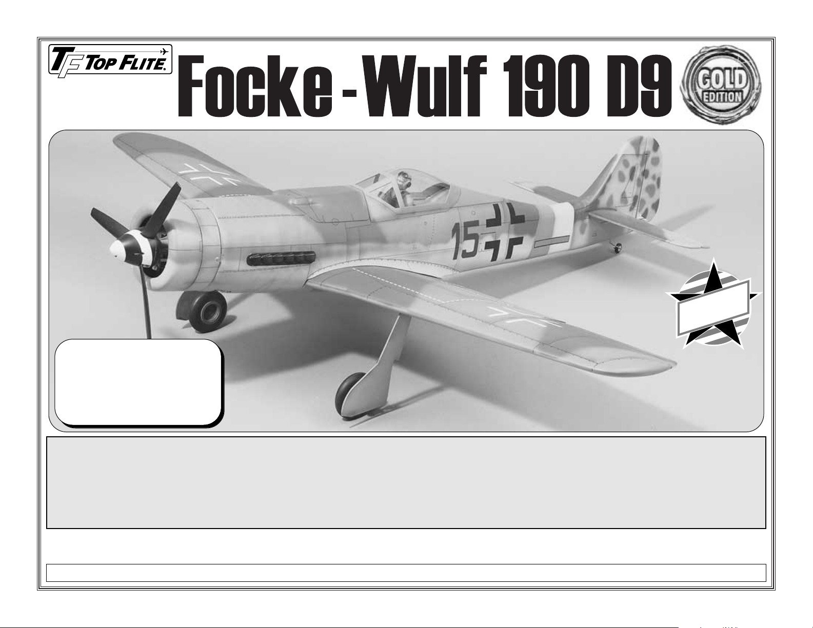
Wingspan: 63.5 in [1613mm]
Wing Area: 711.5 sq in [45.9 sq dm]
Weight: 8 -10 lbs [3.6 - 4.5kg]
Wing Loading: 26-32 oz/sq ft
[80-98 g/sq dm]
Length: 57.75 in [1467mm]
™
MADE IN
USA
Page 2

TABLE OF CONTENTS
INTRODUCTION . . . . . . . . . . . . . . . . . . . . . . . .2
PRECAUTIONS . . . . . . . . . . . . . . . . . . . . . . . . .3
DECISIONS YOU MUST MAKE . . . . . . . . . . . . .3
Engine selection . . . . . . . . . . . . . . . . . . . . . . .3
Exhaust system . . . . . . . . . . . . . . . . . . . . . . . .4
Fixed gear or retracts . . . . . . . . . . . . . . . . . . .4
Flaps . . . . . . . . . . . . . . . . . . . . . . . . . . . . . . . .4
Cockpit & pilot . . . . . . . . . . . . . . . . . . . . . . . . .4
Trim scheme . . . . . . . . . . . . . . . . . . . . . . . . . .4
COMPETITION-MINDED MODELERS . . . . . . . .5
SCALE DOCUMENTATION . . . . . . . . . . . . . . . .5
OTHER ITEMS REQUIRED . . . . . . . . . . . . . . . .5
BUILDING SUPPLIES . . . . . . . . . . . . . . . . . . . .5
Adhesives . . . . . . . . . . . . . . . . . . . . . . . . . . . .5
Tools . . . . . . . . . . . . . . . . . . . . . . . . . . . . . . . .6
COVERING TOOLS & ACCESSORIES . . . . . . .6
IMPORTANT BUILDING NOTES . . . . . . . . . . . .7
METRIC CONVERSIONS . . . . . . . . . . . . . . . . . .7
TYPES OF WOOD . . . . . . . . . . . . . . . . . . . . . . .7
DIE-CUT PATTERNS . . . . . . . . . . . . . . . . . .8 & 9
GET READY TO BUILD . . . . . . . . . . . . . . . . . .10
BUILD THE TAIL SURFACES . . . . . . . . . . . . .10
Build the stabilizer and elevators . . . . . . . . . .10
Finish the elevators . . . . . . . . . . . . . . . . . . . .14
Build the fin . . . . . . . . . . . . . . . . . . . . . . . . . .15
BUILD THE FUSELAGE . . . . . . . . . . . . . . . . .16
Frame the fuse top . . . . . . . . . . . . . . . . . . . .16
Mount the stab and fin . . . . . . . . . . . . . . . . . .18
Sheet the top of the fuse . . . . . . . . . . . . . . . .19
Build the fuse bottom . . . . . . . . . . . . . . . . . . .22
Sheet the bottom of the fuse . . . . . . . . . . . . .23
Mount the tail gear . . . . . . . . . . . . . . . . . . . .24
Build the rudder . . . . . . . . . . . . . . . . . . . . . . .26
Finish the turtle deck . . . . . . . . . . . . . . . . . . .27
Mount the engine . . . . . . . . . . . . . . . . . . . . .28
BUILD THE WING . . . . . . . . . . . . . . . . . . . . . .28
Preparation . . . . . . . . . . . . . . . . . . . . . . . . . .28
Frame the wing panel . . . . . . . . . . . . . . . . . .30
Fit the landing gear . . . . . . . . . . . . . . . . . . . .33
Finish the bottom of the wing . . . . . . . . . . . . .35
Join the wing panels . . . . . . . . . . . . . . . . . . .35
Sheet the bottom of the wing . . . . . . . . . . . . .36
Build the wing tips . . . . . . . . . . . . . . . . . . . . .37
Build the flaps . . . . . . . . . . . . . . . . . . . . . . . .38
Hinge the flaps . . . . . . . . . . . . . . . . . . . . . . .39
Finish building the ailerons . . . . . . . . . . . . . .39
Hook up the flaps and ailerons . . . . . . . . . . .40
Finish the wing . . . . . . . . . . . . . . . . . . . . . . .41
FINAL CONSTRUCTION . . . . . . . . . . . . . . . . .43
Mount the wing to the fuse . . . . . . . . . . . . . .43
Make the wing fillets . . . . . . . . . . . . . . . . . . .45
Build the belly pan . . . . . . . . . . . . . . . . . . . . .46
Assemble the cowl . . . . . . . . . . . . . . . . . . . .47
Mount the muffler . . . . . . . . . . . . . . . . . . . . .48
Hook up the throttle . . . . . . . . . . . . . . . . . . . .49
Install the fuel tank . . . . . . . . . . . . . . . . . . . .50
Test fit the cockpit kit . . . . . . . . . . . . . . . . . . .50
Mount the receiver and battery pack . . . . . . .51
Balance the airplane laterally . . . . . . . . . . . . .52
FINISHING . . . . . . . . . . . . . . . . . . . . . . . . . . . .52
Final preparations . . . . . . . . . . . . . . . . . . . . .52
Trim scheme . . . . . . . . . . . . . . . . . . . . . . . . .52
Cover the model . . . . . . . . . . . . . . . . . . . . . .52
Machine gun cover . . . . . . . . . . . . . . . . . . . .53
Supercharger intake . . . . . . . . . . . . . . . . . . .53
Landing gear covers . . . . . . . . . . . . . . . . . . .54
Display propeller . . . . . . . . . . . . . . . . . . . . . .54
Painting . . . . . . . . . . . . . . . . . . . . . . . . . . . . .54
Exhaust stacks . . . . . . . . . . . . . . . . . . . . . . .55
FINAL ASSEMBLY . . . . . . . . . . . . . . . . . . . . . .56
Join the control surfaces . . . . . . . . . . . . . . . .56
Hook up the controls . . . . . . . . . . . . . . . . . . .56
Mount the canopy . . . . . . . . . . . . . . . . . . . . .57
GET YOUR MODEL READY TO FLY . . . . . . . .57
Balance your model . . . . . . . . . . . . . . . . . . . .57
Set the control throws . . . . . . . . . . . . . . . . . .58
PREFLIGHT . . . . . . . . . . . . . . . . . . . . . . . . . . .59
Identification . . . . . . . . . . . . . . . . . . . . . . . . .59
Charge batteries . . . . . . . . . . . . . . . . . . . . . .59
Balance propellers . . . . . . . . . . . . . . . . . . . . .59
Ground check . . . . . . . . . . . . . . . . . . . . . . . .59
Range check
ENGINE SAFETY PRECAUTIONS . . . . . . . . . .59
AMA SAFETY CODE . . . . . . . . . . . . . . . . . . . .60
CHECK LIST . . . . . . . . . . . . . . . . . . . . . . . . . .60
FLYING . . . . . . . . . . . . . . . . . . . . . . . . . . . . . .61
Fuel mixture adjustment . . . . . . . . . . . . . . . .61
3-VIEW . . . . . . . . . . . . . . . . . . . . . . .Back cover
INTRODUCTION
Thank you and congratulations for purchasing the
Top Flite Gold Edition Focke-Wulf 190 D9. If you
haven’t yet spent much time studying the FockeWulf, you will soon come to realize that, although at
a first glance it appears to be a rather conventional
appearing plane, in actuality the Focke-Wulf has
some very interesting lines and features. And the “D”
model (a “stretched” version of its predecessor, the
A) is the most interesting Focke-Wulf with the
extended nose and aft “fuse plug”. If you’re not
already a big fan of the Focke-Wulf, after a while it
will begin to grow on you.
This 1/7th scale Top Flite Gold Edition model is an
ideal plan-form with long nose and tail moments and
adequate wing area—perfect ingredients for a
smooth flying plane no matter what the type. In spite
of its interesting lines, building this kit is rather
straight-forward. Though the fuse is sheeted in
several sections, none of the contours should
present any difficulty for the average modeler
(especially since the sheeting is only 1/16" thick). In
the wing, pneumatic retract installation is
straightforward with suggestions on air line routing
and other details. The characteristic extra long
landing gear struts, and the structural problems they
present, have been addressed by slightly shortening
the struts and by reinforcing the landing gear area
with 1/8" birch ply landing gear webs.
With this kit you can achieve whatever level of detail
you like. Just by following the instructions and
finishing the plane in a scale-looking trim scheme,
beginning scale modelers will end up with a model
that very much represents a full-size Fw 190D.
Experienced builders will find ways to add even more
detail, making this Top Flite
Gold Edition
kit
competitive in scale competition.
- 2 -
Page 3
Your Focke-Wulf is not a toy, but a sophisticated
working model that functions very much like a fullsize airplane. Because of its realistic performance, if
you do not assemble and operate your Focke-Wulf
correctly, you could possibly injure yourself or
spectators and damage property.
If this is your first scale model, get the
assistance of an experienced modeler who has
flown this type of plane before. Once completed,
your Focke-Wulf will have much value. An
experienced modeler can help you with “pre-flight”
and possibly identify something you may have
overlooked during construction or setup. He can also
help you with your first few flights. If you’re not
already a member of a club, contact the Academy of
Model Aeronautics (AMA), which has more than
2,500 chartered clubs across the country. AMA
Membership is required at chartered club fields
where experienced modelers and qualified flight
instructors are available. Contact the AMA at the
address or toll-free phone number below.
Academy of Model Aeronautics
5151 East Memorial Drive
Muncie, IN 47302
(800) 435-9262
Fax (765) 741-0057
or via the Internet at: http://www.modelaircraft.org
1. You must build the plane according to the plan and
instructions. Do not alter or modify the model, as
doing so may result in an unsafe or unflyable model. In
a few cases the plan and instructions may differ
slightly from the photos. In those instances the
plan and written instructions are correct.
2. You must take time to build straight, true and strong.
3. You must use a proper R/C radio that is in first
class condition, the correct sized engine and correct
components (fuel tank, wheels, etc.) throughout
your building process.
4. You must properly install all R/C and other
components so that the model operates properly on
the ground and in the air.
5. You must test the operation of the model before
every flight to insure that all equipment is operating
and you must make certain that the model has
remained structurally sound.
6. If you are not already an experienced R/C pilot,
you must fly the model only with the help of a
competent, experienced R/C pilot.
Please inspect all parts carefully before starting
to build! If any parts are missing, broken or
defective, or if you have any questions about
building or flying this model, please call us at:
(217) 398-8970
or e-mail us at
productsupport@top-flite.com
We’ll be glad to help. If you are calling for
replacement parts, please look up the part
numbers and the kit identification number
(stamped on the end of the carton) and have
them ready when you call.
ENGINE SELECTION
Recommended engine size:
.61 to .75 cu. in. [10.0 - 12.0cc] 2-stroke
-or-
.70 to .91 cu. in. [11.5 - 15.0cc] 4-stroke
Your Focke-Wulf will fly well with any of the
recommended engines. 4-stroke engines and
most .75 cu. in. 2-stroke engines will turn a larger
prop at lower RPM.This is often desirable for scale
realism. However, many .61 cu. in. 2-stroke
engines produce about as much horsepower as
.75 2-stroke and will fly the Focke-Wulf extremely
well. If you use a .61 2-stroke engine, a ball
bearing, Schnuerle-ported engine is
recommended. Our flying prototype flew on an
O.S.®MAX .61 FX. This engine provided excellent
performance and more than enough power.
Although larger engines may be used, the extra
horsepower is not needed.
The included adjustable engine mount will hold a
range of engines from .61 cu. in. 2-stroke through
.91 cu. in. 4-stroke.
DECISIONS YOU MUST MAKE
NOTE: We, as the kit manufacturer, provide you
with a top quality kit and great instructions, but
ultimately the quality and flyability of your finished
model depends on how you build it; therefore, we
cannot in any way guarantee the performance of
your completed model, and no representations
are expressed or implied as to the performance or
safety of your completed model.
Your Top Flite Gold Edition Focke-Wulf is
intended for scale and general sport flying
including mild aerobatics such as loops, stall
turns, rolls, etc. Its structure is designed to
withstand such stresses. If you intend to use
your Focke-Wulf for more rigorous types of flying
such as racing or aggressive aerobatics, it is
your responsibility to reinforce areas of the
model that will be subjected to the resulting
unusually high stresses.
PROTECT YOUR MODEL,
YOURSELF & OTHERS
FOLLOW THESE IMPORTANT
SAFETY PRECAUTIONS
- 3 -
Page 4

COCKPIT AND PILOT
Your model won’t be complete without the Top Flite
Focke-Wulf Cockpit Kit (TOPQ8411). It includes
the floor, side panels, instrument panel, seat,
headrest and hardware. The cockpit kit can be
installed after the fuselage is completed, but is
easier to install if you have it on hand during
construction. Should you choose not to install the
scale Top Flite Cockpit Kit, you could leave the
cockpit empty or make your own cockpit from
balsa or thin cardboard (from cereal boxes.)
Top Flite also offers a 1/7 scale WW II American
Full Body Pilot (he could be painted in German
flight gear!). The order number is TOPQ9000.
TRIM SCHEME
The model on the kit box was covered with dove
gray Top Flite MonoKote®film, then painted with
Testors Model Master Acrylic paint followed by a
clear-coat of Top Flite LustreKote®flat clear. A
painted finish is the only way to reproduce the spray
painted camouflaged “patchwork” trim schemes
found on full-size Focke-Wulfs. If you do decide to
paint your model, the balsa skin must first be
covered either with MonoKote film, glass cloth and
resin, or another type of covering. Refer to the
Finishing
section near the back of the manual for
more details that may help you decide how to finish
your model. Since you don’t have to finish it today,
there is time to seek the advice of experienced
builders in your club who can give you tips on how
to prep, cover and paint a balsa model.
If you prefer not to do the work required of a
painted trim scheme, you may find a simpler scale
trim scheme, or make up your own scaleappearing trim scheme simply by covering the
Focke-Wulf with a few of the flat military MonoKote
colors such as dove gray, olive drab, cream, tan,
sky blue, insignia blue and black.
These items are required for retractable landing gear:
CJM Focke-Wulf retractable landing gear
(CJMQ3072)
Robart #164G Hand Pump with Gauge
(ROBQ2363)
Williams Bros. #143 3-3/4" Smooth Contour
Wheels (WBRQ1143)
Servo for the air control valve (micro or mini
servo preferred)
Light weight glass cloth to reinforce wing
sheeting in wheel wells (HCAR5000)
(8) #6 x 1/2" screws (GPMQ3160, pkg. of 8)
These items are required for fixed landing gear:
3-3/4" Main Wheels
(4) 3/16" wheel collars (GPMQ4308)
FLAPS
The Focke-Wulf is designed to incorporate scale
split flaps; however, flaps are optional and not
necessary for an excellent flying experience.
Without flaps, the takeoff roll is longer and the
landing speed is faster.
Flaps are not difficult to build, but they do require
good craftsmanship to fit well. Flaps add nicely to
the model’s flight characteristics and scale
appearance, and are highly recommended for
those who wish to install them. You will find
additional information on the use of the flaps in the
Flying
section near the end of this manual.
For Flaps, you will need the following additional
items:
Two standard servos
(1) Y-connector (HCAM2500 - Futaba
®
J)
(6) Small Pivot Point Hinges
(GPMQ4001, pkg. of 15)
EXHAUST SYSTEM
A Top Flite header and muffler are available that
will fit inside the cowl. They are designed for
2-stroke engines mounted inverted as used on the
model and shown in the instructions.
Headers for:
O.S.
®
.61SF, SX - TOPQ7920
SuperTigre
®
.61-.75 K series (muffler bolts
go through the muffler and screw into the
engine) - TOPQ7925
SuperTigre .61-.75 G series (muffler bolts go
through the engine and screw into the muffler)
- TOPQ7926
.61-.75 Warbird In-Cowl Muffler, TOPQ7915
There may be other exhaust systems that will work
with this model. If you prefer to use another
exhaust system, consider any modifications that
may have to be made to accommodate it. It may
be helpful to get your exhaust system as soon as
possible and place it over the plan to visualize how
it will fit. This will minimize delays when you get to
that point.
FIXED GEAR OR RETRACTS
You may build your Focke-Wulf with either fixed or
retractable landing gear. The pre bent landing gear
wires are included to build the kit with fixed gear.
Should you decide to install retracts, detailed
instructions are provided. The Gold Edition FockeWulf is designed to accept the Century Jet Models’
#39025 pneumatic retracts. You may use other
retractable landing gear systems but it is up to you
to make any modifications necessary. A micro
servo was used in the prototype to operate the air
control valve. A standard servo could be used for
this, but will take up a bit more room.
- 4 -
Page 5

COMPETITION-MINDED MODELERS
The outline of the Top Flite
Gold Edition
Focke-Wulf
D9 was derived from three-view drawings, photos
and highly detailed static kits. Some areas of the
outline have been slightly changed to improve flight
characteristics. Notably, the area of the “tail feathers”
has been increased to improve directional stability
and control. The landing gear struts have been
shortened slightly to improve handling and durability,
and do not retract fully into the wing, but protrude
below the wing approximately 1/8".
The approximate scale of this model is 1:6.5.
If you plan to enter your Focke-Wulf in scale
competition (it’s lots of fun, and the runways are
usually paved!), this kit may be entered in Fun Scale,
Sportsman Scale and Expert Scale classes in AMA
competition. All classes have the same flight
requirements in which you must perform ten
maneuvers, five of which are mandatory. The other
five are up to you—“easy” stuff like a slow, low
inspection pass with flaps extended, or maybe a
touch-and-go. If you have never competed in a scale
contest, you could start out in Fun Scale. In Fun Scale,
the only documentation required is any proof that a
full-size aircraft of this type, in the paint/markings
scheme on your model, did exist. A single photo, a kit
box cover from a plastic model, or even a painting is
sufficient proof! If you’re interested, contact the AMA
for a rule book that will tell you everything you need to
know. You can find a contest schedule in the back of
the AMA magazine (Model Aviation).
One last note for those who are interested in scale
competition; Strive to build your model to reflect your
documentation. Whatever lines and features appear
on the full size plane should also appear on your
model. Refer to the photos and documentation of the
Focke-Wulf you are using for your model.
SCALE DOCUMENTATION
Three-view drawings and photo packs of full size
Focke-Wulfs are available from:
Scale Model Research
3114 Yukon Ave.
Costa Mesa, CA 92626
(714) 979-8058
Fax: (714) 979-7279
Even if you’re not intending to build your Fw 190D for
competition, photos and color drawings are
extremely useful for completing much of the detail
work such as the machine gun cover, landing gear
covers, antenna mast, panel lines, etc.
Squadron/Signal Publications has a series of books
with dozens of close-up photos and highly accurate
color drawings featuring trim schemes that may help
you decide how to finish your model. One of the
Focke-Wulf books is listed below and is available
from most hobby shops.
Fw 190D Walk Around, No. 5510 (order number
SSPZ5510)
OTHER ITEMS REQUIRED
These are the additional items you will need to
complete your Focke-Wulf 190D that have not
already been mentioned and are not included with
the kit. Order numbers are in parentheses
(HCAM2200). TOP is the Top Flite brand, GPM is the
Great Planes®brand and HCA is the Hobbico®brand.
❏ 4 to 6-Channel radio with 5 to 8 servos
❏ (2) 24" Servo extension cords ailerons
(HCAM2200 - Futaba J)
❏ Switch/charging jack mount kit (GPMM1000)
❏ Propellers (refer to the instructions that come
with your engine)
❏ 14 oz. Fuel tank (GPMQ4106)
❏ Fuel line (2’, GPMQ4131)
❏ Fuel filler valve for glow fuel (GPMQ4160)
❏ 1" Tailwheel (GPMQ4241)
❏ 3/32" Wheel collar for tailwheel (GPMQ4302)
❏ R/C Foam padding (1/4", HCAQ1000, or 1/2",
HCAQ1050)
❏ Top Flite MonoKote covering (
see
Finishing
section)
❏ Paint (
see
Finishing section)
❏ 3" Spinner (GPMQ4530, white)
BUILDING SUPPLIES
Here’s a list of supplies you should have on hand
while you’re building. Some of these are optional.
Use your own experience to decide what you need.
We recommend Great Planes Pro CA and Epoxy.
ADHESIVES
❏ 2 oz. Thin CA (GPMR6003)
❏ 2 oz. Medium CA+ (GPMR6009)
❏ 2 oz. Thick CA- (GPMR6015)
❏ CA Accelerator (GPMR6035)
❏ CA Debonder (GMPR6039)
❏ CA Applicator Tips (HCAR3780)
❏ 30-minute epoxy (GPMR6047), or 45-minute
(GPMR6048) epoxy
❏ 6-minute epoxy (GPMR6045)
❏ Pro Wood Glue (GPMR6161)
❏ J & Z Products
Z RC/56
canopy glue (JOZR5007)
❏ Microballoons (TOPR1090)
❏ Milled Fiberglass (GPMR6165)
❏ Lightweight Hobby Filler (Balsa Color, HCAR3401)
❏ Auto body filler (Bondo®or similar)
❏ Denatured or Isopropyl Alcohol (to clean up
excess epoxy)
❏ 3M 75 Repositionable spray adhesive
(MMMR1900)
- 5 -
Page 6
TOOLS
❏ #11 Blades (HCAR0311, 100 qty.)
❏ Single Edge Razor Blades (HCAR0312, 100 qty.)
❏ Razor Plane (MASR1510)
❏ Hobbico Builder’s Triangle (HCAR0480)
❏ T-Pins (HCAR5100 — small,
HCAR5150 — medium, HCAR5200 — large)
❏ Drill Bits: 1/16", 3/32", 7/64", 1/8", 5/32", 3/16",
7/32", 1/4", #29 (or 9/64", or Great Planes 8-32
tap and drill set listed below), #7 (or 13/64", or
Great Planes tap and drill set listed below), #12
(for enlarging wheels to fit on axles of CJM
retracts), or #9 (or 13/64" for enlarging wheels
for fixed landing gear)
❏ 1/4-20 Tap and drill (GPMR8105)
❏ 8-32 Tap and drill (GPMR8103)
❏ Tap wrench (GPMR8120)
❏ Kyosho
®
Lexan
®
Curved Scissors (KYOR1010)
❏ Long handle 9/64" ball end hex wrench
(GPMR8004)
❏ Silver Solder (GPMR8070 w/flux)
❏ Masking Tape (TOPR8018)
❏ Great Planes
®
Plan Protector™(GPMR6167) or
wax paper
❏ Dremel
®
#178 cutting bit (for countersinking
screws in the servo hatch covers)
❏ Robart
®
Super Stand II (ROBP1402)
❏ Easy–Touch
™
Bar Sanders*
Note: In several instances the manual suggests
using K & S brass tubing sharpened at one end to
cut accurate, clean holes in balsa. Use a rotary tool
with a cut-off wheel to sharpen the outside edge of
the tube, and a hobby knife to sharpen the inside
edge of the tube. The sizes of tubing used are 1/8",
3/16" and 5/32".
COVERING TOOLS AND
ACCESSORIES
Top Flite Heat Gun (TOPR2000)
Top Flite Trim Seal Tool (TOPR2200)
-andTop Flite Sealing Iron (TOPR2100)
Top Flite Hot Sock
™
(TOPR2175)
-or21st Century®Sealing Iron (COVR2700)
21st Century Cover Sock (COVR2702)
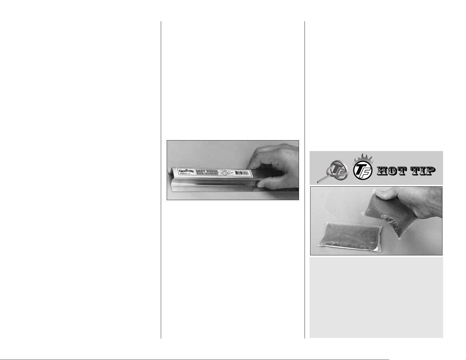
EASY-TOUCH™BAR SANDER
A flat, durable, easy to handle sanding tool is a
necessity for building a well finished model. Great
Planes makes a complete range of Easy-Touch Bar
Sanders (patented) and replaceable Easy-Touch
Adhesive-backed Sandpaper. While building the
Focke-Wulf we used two 5-1/2" Bar Sanders and two
11" Bar Sanders equipped with 80-grit and 150-grit
Adhesive-backed Sandpaper.
Here’s the complete list of Easy-Touch Bar Sanders
and Adhesive Backed Sandpaper:
5-1/2" Bar Sander (GPMR6169)
11" Bar Sander (GPMR6170)
22" Bar Sander (GPMR6172)
33" Bar Sander (GPMR6174)
44" Bar Sander (GPMR6176)
11" Contour Multi-Sander (GPMR6190)
12’ roll of Adhesive-backed:
80-grit sandpaper (GPMR6180)
150-grit sandpaper (GPMR6183)
180-grit sandpaper (GPMR6184)
220-grit sandpaper (GPMR6185)
Assortment pack of 5-1/2" strips (GPMR6189)
We also use Top Flite 320-grit (TOPR8030, 4 sheets)
and 400-grit (TOPR8032, 4 sheets) wet-or-dry
sandpaper for finish sanding.
We recommend using plastic bags filled with lead
shot for building weights. They assume the shape
of the curved surfaces to apply uniform pressure
without making dents in the balsa. You can
purchase shot at sporting goods stores where
hunting supplies are sold. We use #6 lead shot.
One 25 lb. bag costs about fifteen to twenty dollars.
You can use small sealable food storage bags to
hold the shot. Tape them shut for security. Each bag
holds about two to three pounds.Ten to fifteen bags
may be required for this model.
- 6 -
Page 7
IMPORTANT BUILDING NOTES
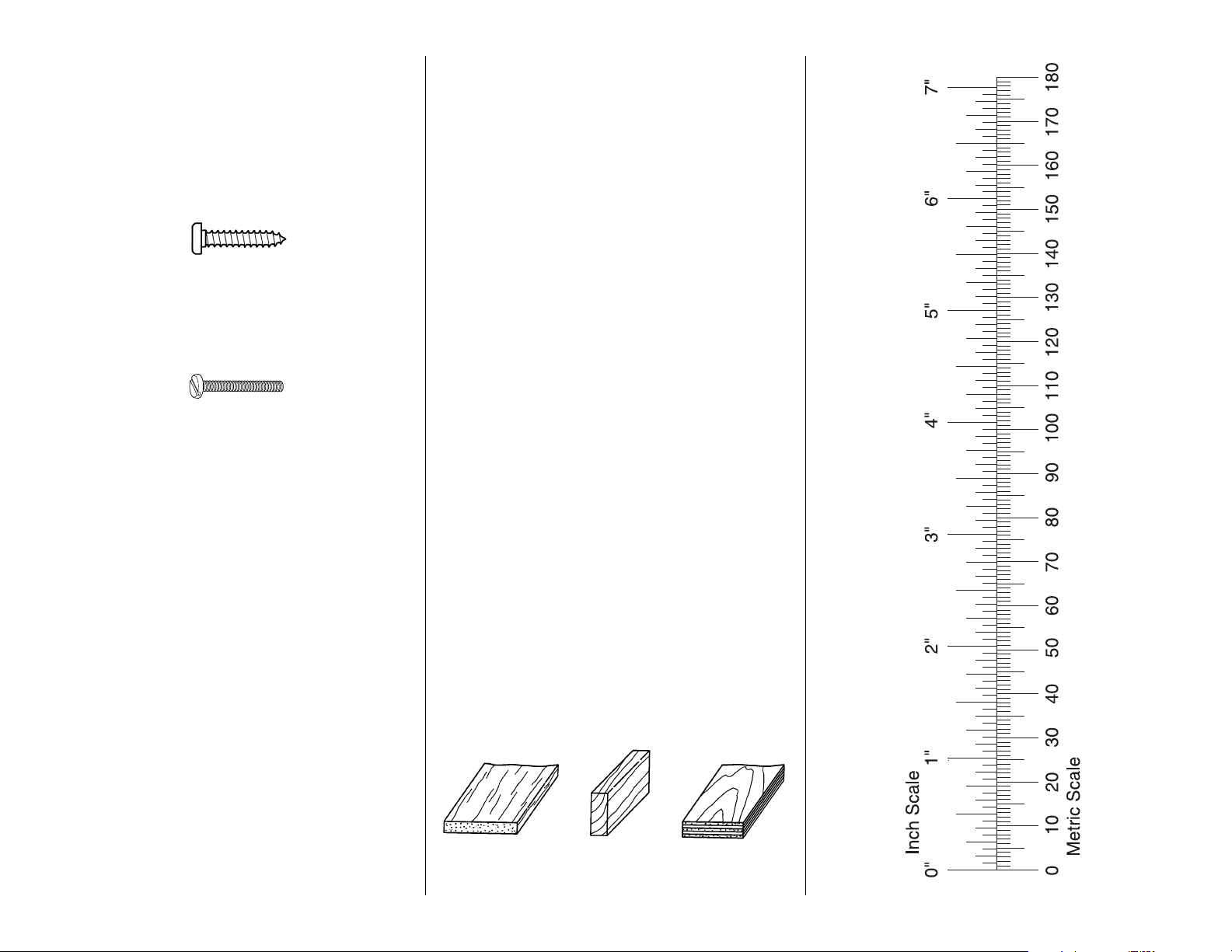
There are two types of screws used in this kit:
Sheet metal screws are designated by a number
and a length.
For example #6 x 3/4" long [1.91mm]
Machine screws are designated by a number,
threads per inch, and a length.
For example 4-40 x 3/4" long [1.91mm]
•
When you see the term
test fit
in the instructions,
it means that you should first position the part on
the assembly without using any glue, then
slightly modify or
custom fit
the part as necessary
for the best fit.
•
Whenever the term
glue
is written you should rely
upon your experience to decide what type of glue to
use. When a specific type of adhesive works best for
that step the instructions will make a recommendation.
•
Whenever just
epoxy
is specified you may use
either
30-minute epoxy or6-minute epoxy. When
30-minute epoxy is specified it is highly
recommended that you use only 30-minute (or
45-minute) epoxy because you will need the
working time and/or the additional strength.
•
Occasionally we refer to the
top
or
bottom
of the
model or
up
or
down
. To avoid confusion, the
top
or
bottom
of the model is as it would be when the
airplane is right side up and will be referred to as
the top even if the model is upside-down during
that step,
i.e.
the top main spar is always the top
main spar even if the wing is upside-down when
you are working on it. Similarly,
move the former
up
means move the former toward the top of the
fuselage even if the fuselage is upside-down when
you are working on it.
•
When you get to each step, read that step
completely through to the end before you begin.
Frequently there is important information or a note
at the end of the step that you need to know before
you start.
•
Photos and sketches are placed before the step
they refer to. Frequently you can study photos in
following steps to get another view of the same parts.
TYPES OF WOOD
BALSA BASSWOOD PLYWOOD
1/64" = .4mm
1/32" = .8mm
1/16" = 1.6mm
3/32" = 2.4mm
1/8" = 3.2mm
5/32" = 4mm
3/16" = 4.8mm
1/4" = 6.4mm
3/8" = 9.5mm
1/2" = 12.7mm
5/8" = 15.9mm
3/4" = 19mm
1" = 25.4mm
2" = 50.8mm
3" = 76.2mm
6" = 152.4mm
12" = 304.8mm
15" = 381mm
18" = 457.2mm
21" = 533.4mm
24" = 609.6mm
30" = 762mm
36" = 914.4mm
METRIC CONVERSION
1" = 25.4mm (conversion factor)
- 7 -
Page 8
- 8 -
DIE-CUT PATTERNS
Page 9
- 9 -
DIE-CUT PATTERNS
Page 10
GET READY TO BUILD
❏ 1. A miniaturized building plan is included in the
middle of this manual. It may be removed and used as
a quick, handy reference, so you don’t have to get out
the full-size plan when you are not building over it.
❏ 2. If you’ve already purchased your retractable
landing gear, or as soon as you do, take the air lines
out of the package, unravel them and hang them
somewhere in your shop. By the time you are ready
to install the air lines, all the kinks will be out and
they’ll be easier to work with.
❏ 3. Remove all the parts from the box. Use a
ballpoint pen (not a felt tip pen) to lightly write the
name or size on each piece so you can identify it later.
Use the
die-cut patterns
on pages 8 & 9 to identify
and mark the die-cut and laser-cut parts before you
remove them from their die sheets. Place a
straightedge across the punchmarks on the die sheet
on both sides of the forward wing joiner and draw a
centerline. When it's time to join the wing halves, the
centerline can be used to align the forward wing joiner.
Many of the parts already have numbers stamped on
them, but in some cases the numbers are located
alongside the parts or only on the die drawings in the
manual. You may remove all the die-cut parts from
their die sheets now, or wait until you need them. If a
part is difficult to remove, don’t force it out, but cut
around it with a hobby knife and a #11 blade. After you
remove the parts from their die sheets, lightly sand the
edges to remove slivers or die-cutting irregularities.
Save some of the larger scraps of wood.
❏ 4. Separate the parts into groups such as stab,
fin, wing, and fuse. Store smaller parts in zipper-top
food storage bags.
BUILD THE TAIL SURFACES
Build the stabilizer and elevators
❏ 1. Cut the stab plan from the fuse plan sheet and
place it over your building board. Cover the stab plan
with Great Planes Plan Protector or waxed paper to
protect it from glue. Note: If you are a neat builder,
there is no need to protect the plan as the glue joints
are raised off the plan.
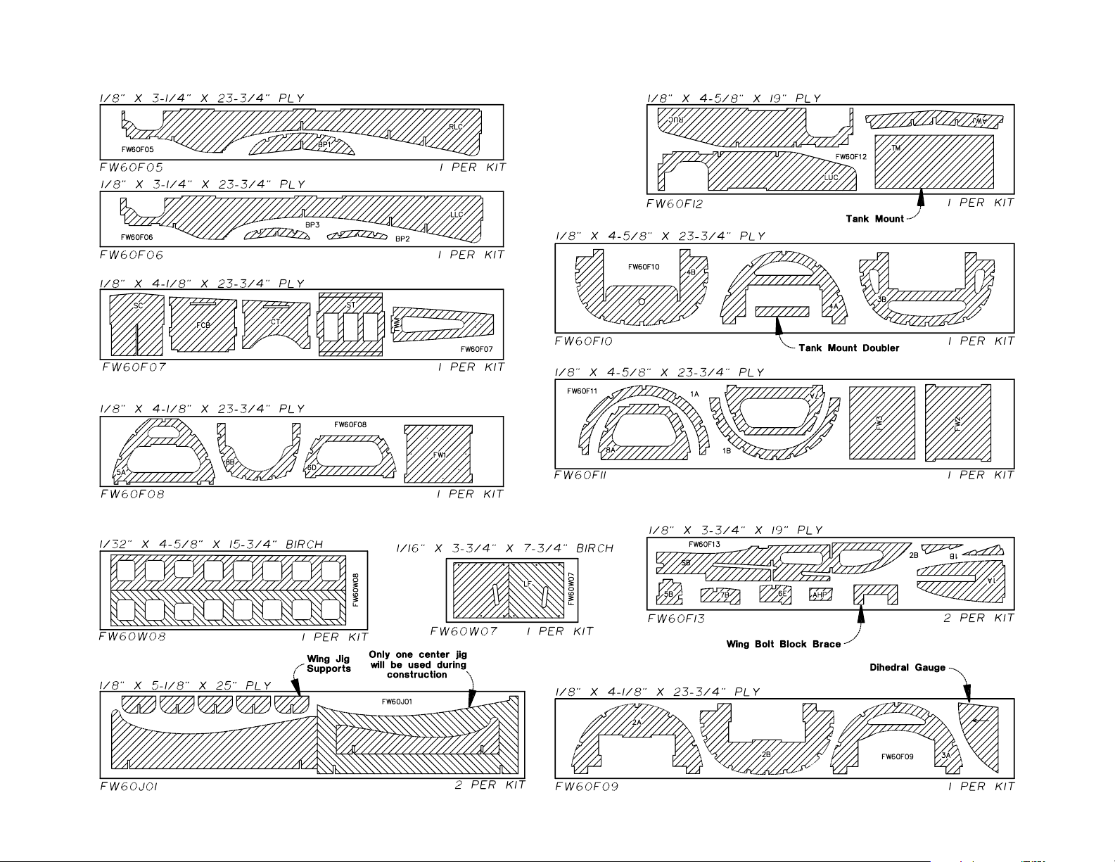
❏ 2. Use a single-edge razor blade to extend the
slots through the leading edge in the die-cut 3/32"
balsa stab ribs S-1 and S-2.
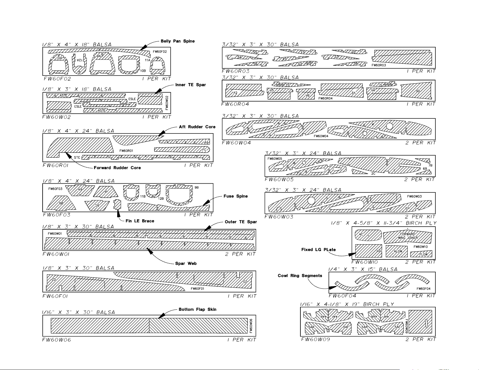
❏ 3. Without using any glue, join S-1 and both S-2’s
to the die-cut 1/8" plywood stab center. Join the stab
center with the ribs to the die-cut 1/8" balsa stab TE
(trailing edge), followed by the rest of the stab ribs
and the die-cut 1/8" balsa elevator LE (leading
edge) spars.
❏ 4. Position the assembly over the stab plan. Cut
twenty 2-1/2" long rib jig sticks from two 1/4" x 1/4"
x 30" balsa sticks. Pin the rib jig sticks to the building
board on both sides of all the ribs (except S-1). As
you can see, the rib jig sticks securely hold the ribs
to the plan, yet will allow easy removal of the stab
from the building board after the sheeting is glued
into position. Temporarily remove the stab center to
position the rib jig sticks on the inside edges of ribs
S-2. Note: Make sure the T-pins do not protrude
above the ribs so they will not interfere with the top
stab sheeting that will be added later.
❏ 5. Make certain the stab TE is aligned over its
location on the plan and that the jig tabs of all the ribs
are contacting the plan. Use medium CA to glue the
stab TE to the ribs. Note: Make certain both S-6’s
remain perpendicular to the plan. This way the stab
and elevator tip blocks will align with the stab when
it’s time to glue them on.
- 10 -
Page 11
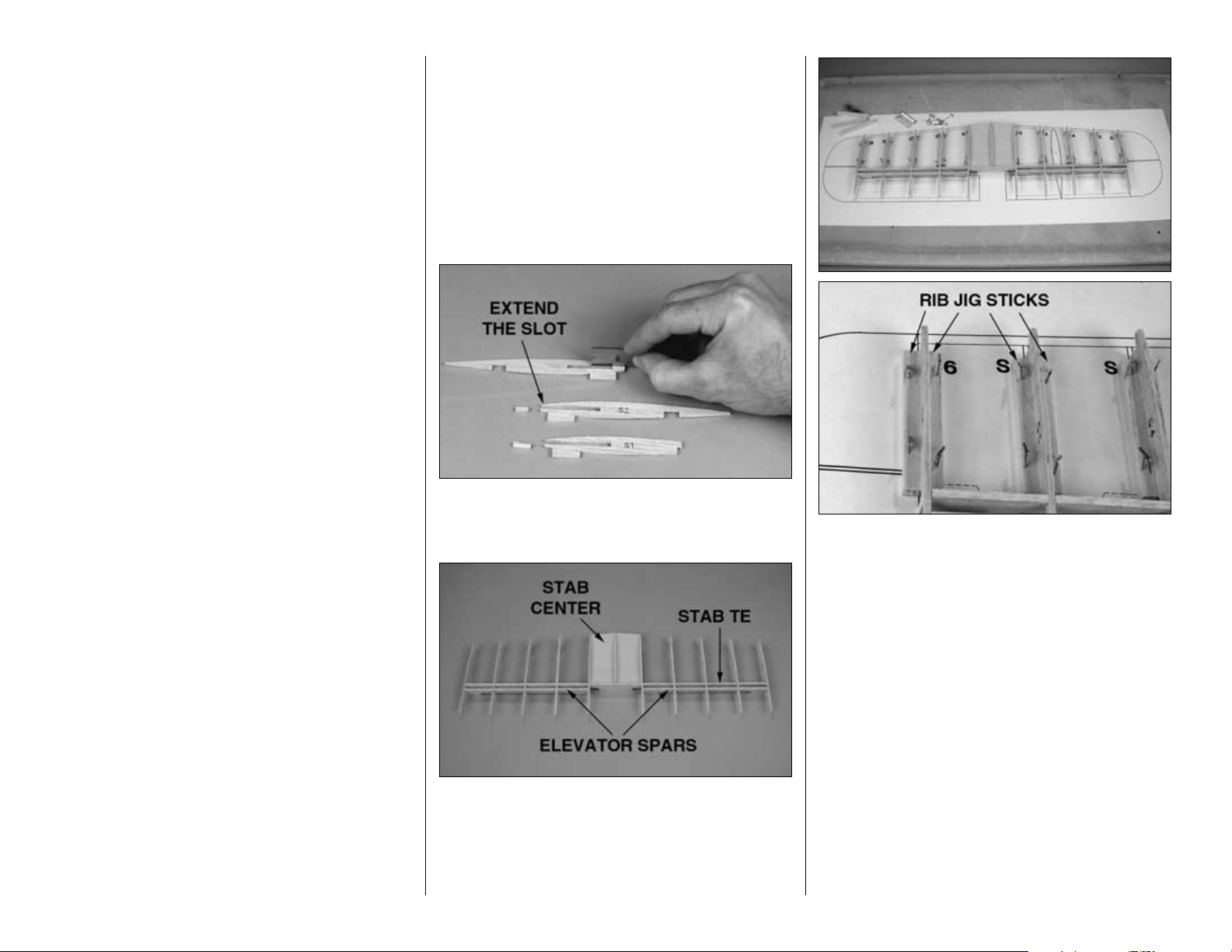
❏ 6. Cut 2" from a 3/16" x 3/16" x 30" balsa stick.
Use medium CA to glue the elevator LE spars to the
ribs, inserting the stick between the elevator LE spar
and the stab TE at each rib as you glue it.
❏ 7. Use a bar sander with 80-grit sandpaper or a
hobby knife to carefully bevel the front of the ribs to
match the aft sweeping angle of the LEs. Cut the 30"
long shaped balsa stab LE to the correct length for
both LEs. Glue them, centered vertically, to the front
of the ribs and stab center.
❏ 8. Use a bar sander with 80-grit sandpaper to
sand the tops of the ribs, the stab TE and the
elevator LE spars so they are all even.
❏ 9. Use the 1/16" x 3" x 30" balsa sheets supplied
with this kit and select four of the softer (and lighter)
sheets to be used for sheeting the tail surfaces.
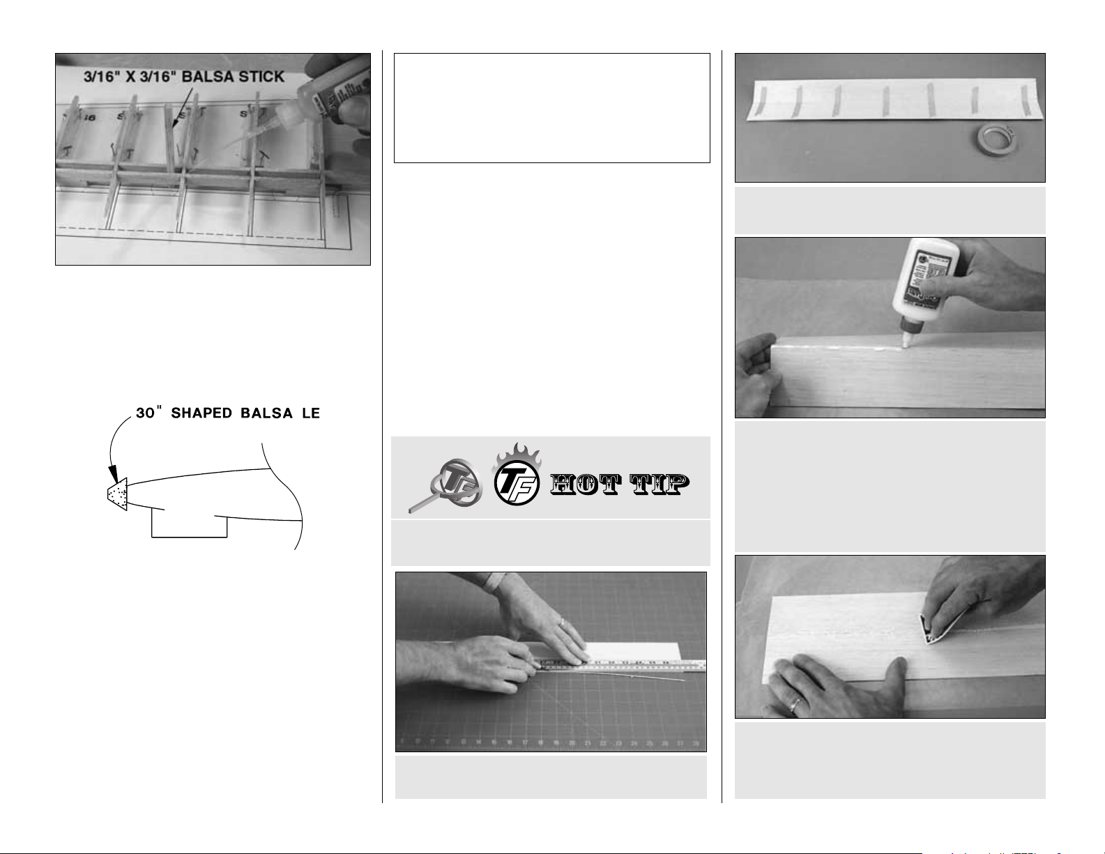
❏ 10. Use your own method or the
Hot Tip
that
follows to make two 1/16" x 6" x 30" sheets from the
four balsa sheets you selected in the previous step.
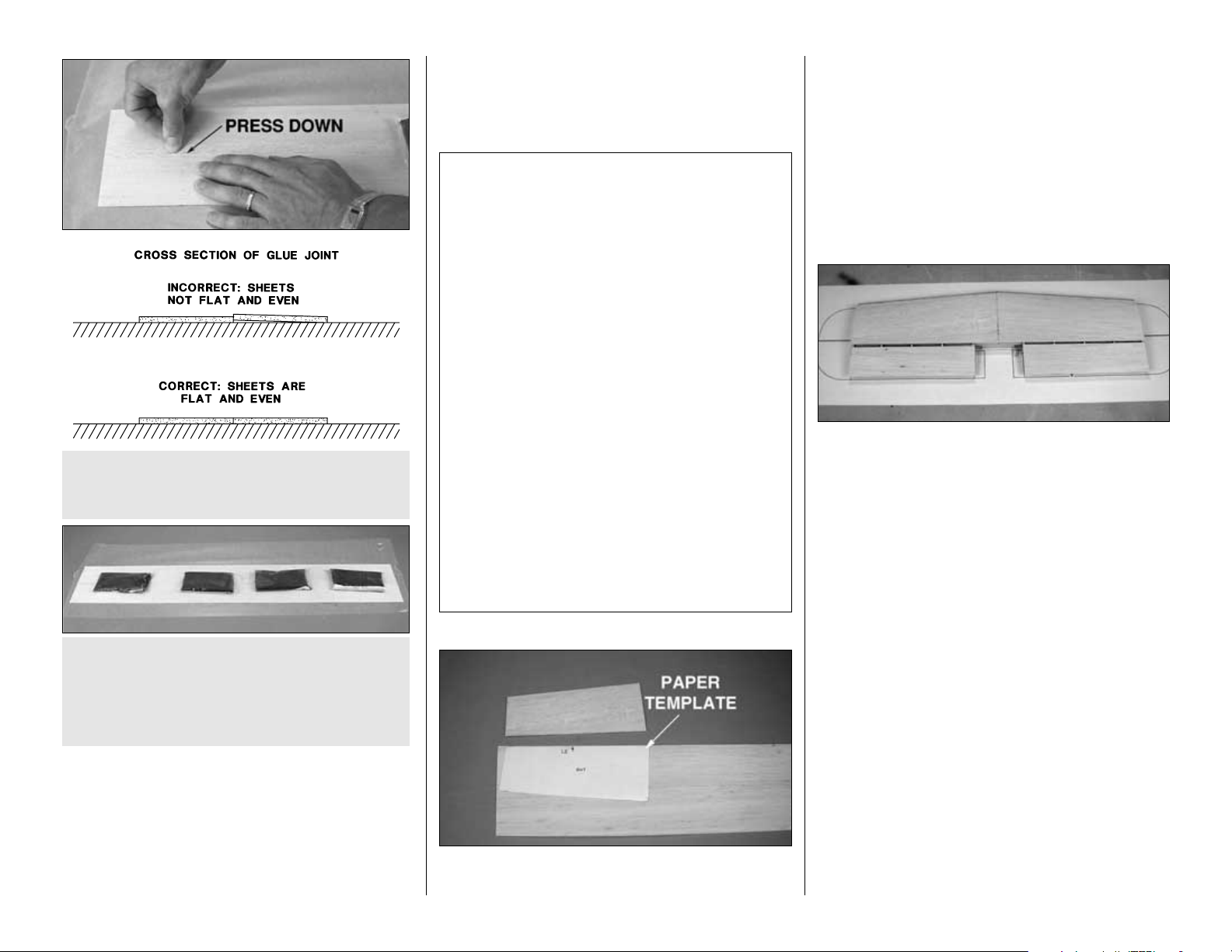
D. Lay the sheets on your workbench covered with
wax paper. Use a credit card or something similar
as a squeegee to simultaneously press the sheets
flat as you wipe the glue from the seam.
C. Turn the sheets over and apply slow drying
glue like Great Planes Pro aliphatic resin to the
joining edges. Some prefer to use CA, but it is not
recommended in this
Hot Tip
because CA does
not allow enough working time to align the sheets
and it is much harder than the balsa, making
sanding difficult.
B. Use masking tape to tightly tape the trued
edges of the sheets together.
A. Use a straightedge to true one edge of two
balsa sheets.
HOW TO MAKE THE STAB SKINS
Top Flite selects balsa that is intended for sheeting,
though occasionally a few of these sheets may
have a small nick or split near the ends. If your kit
contains a few of these sheets, arrange them and
glue them together so the defects will not interfere
with the final shape of the skin.
-11-
Page 12
Note: Some modelers tend to sand the sheeting too
much after it is applied to the structure, making thin
spots where fingers can easily go through. By
following the procedure above (specifically, by aligning
the joined edges of the sheets as shown in step E),
little sanding should be required. Most of the sanding
that isrequired should be done before the sheeting is
glued in place. The only sanding that should be
required after the sheeting is glued to the structure is
final sanding with 320 or 400-grit sandpaper.
❏ 11. Make four stab skins from the two 1/16" x 6"
x 30" balsa sheets you prepared in the previous
steps (you can get three skins from one sheet, but
will have to use the second sheet for the fourth skin).
Note that the grain is parallel with the LE. Hint: Make
a paper template and use it to make the skins.
Always cut the skins slightly oversize to allow for
trimming and positioning. Save the leftover sheeting
for the elevators and fin.
Refer to this photo for the following two steps.
❏ 12. Glue two of the skins to the top of the stab.
Usually we recommend using aliphatic resin for this
because of the time required for accurate positioning
and adjustment. However, this is a relatively small
stab, so if the skins fit well and you can work quickly,
medium CA may be used.
❏ 13. Use the smaller pieces of leftover balsa
sheeting to make four elevator skins. Glue two of
the skins to the top of the elevators.
❏ 14. Lift the stab from the building board. The ribs
should slide out from in between the rib jig sticks.
Glue the bottom of the stab center (where you
couldn’t reach when the stab was pinned to the
building board) to the rest of the structure.
Here are a few other things to keep in mind
while sanding balsa sheeting:
1. Make sure you sand the sheets on a flat work
surface that is free from hardened drops of glue or
other imperfections that will damage your
sheeting.
2. Sand the sheeting only as much as required.
The inside of the sheeting needs to be sanded just
enough to remove excess glue and doesn’t have
to be perfectly flat or smooth.
3. Though more material can be removed by
sanding across the grain, this leaves scratches in
the balsa. Balsa sheeting should be sanded with
the grain—especially when finish-sanding.
4. If some of the glue joints are uneven, it may be
best just to leave them that way, rather than to
sand the sheets too thin. A slightly uneven glue
joint is preferable to paper-thin balsa.
F. Place weights on top of the sheet to hold it flat
while the glue dries.
G. After the glue dries, sand the sheets flat
and even.
E. Press the joining edges of the sheets down to
make sure they are even. This is important. Little
sanding will be required if the sheets are even.
-12-
Page 13
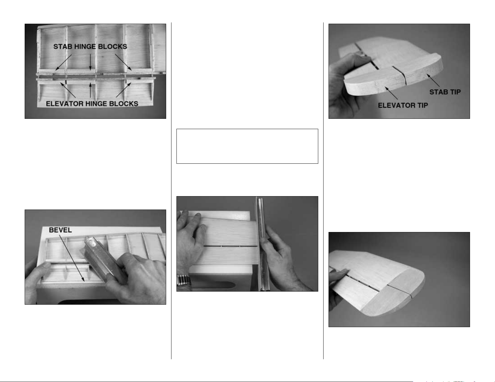
❏ 15. Cut the stab and elevator hinge blocks from
a 1/4" x 3/8" x 30" balsa stick and glue them into
position where shown on the plan.
❏ 16. Use a hobby knife to carefully trim the jig tabs
from the bottom of the ribs, the stab TE and the
elevator TE spars. Use a bar sander with 80-grit
sandpaper to sand the hinge blocks even with the
bottom of the stab and elevators.
❏ 17. Position the stab on your workbench or a flat
platform so that the TE of one of the elevator skins is
even with the edge. Carefully sand a bevel to the
elevator skin until the TE is 1/32" thick. The elevator
ribs will set your bar sander at the correct angle. The
line in the photo indicates the bevel. Sand the other
elevator skin the same way.
❏ 18. Sand a similar bevel to the inside of the
remaining two elevator skins. Glue the skins to the
bottom of the elevators.
❏ 19. Glue the bottom stab skins to the bottom of the
stab. Press the sheeting down evenly, being careful
not to add any twist.
❏ 20. Sand the sheeting on both ends of the stab
even with S-6.
❏ 21. Trim the top and the bottom of the stab LE’s
even with the sheeting, but don’t round them until
instructed to do so.
Refer to this photo for the following two steps.
❏❏22. Place one of the shaped 5/8" balsa stab
tips and one of the shaped 5/8" balsa elevator tips
over the plan (to be certain you identify the parts
correctly—they look similar to each other). Glue the
stab tip to the right side of the stab.
❏❏23. Slightly round the LE of the elevator tip. Glue
the elevator tip to the end of the elevator, but not to
the stab, with about a 1/16" space between them.
❏❏24. Shape the tips even with the stab and
elevator, but do not round them yet. Our preferred
method for shaping balsa tips is to first use a razor
plane, followed by a bar sander.
The stab is symmetrical. Now that it’s sheeted
there is no longer a “top” or a “bottom.” At any time
you can decide which surface looks the best and
designate that as the top.
-13-
Page 14

❏❏25. Finish shaping the stab and elevator tips by
rounding the corners. Round the LE on the right side
of the stab to match the cross-section on the plan.
❏ 26. Repeat the previous four steps for the left side
of the stab.
Finish the elevators
❏
1. Use a razor saw to cut through the ribs, freeing
both elevators from the stab.
❏ 2. Sand the protruding ends of the ribs and the
stab sheeting even with the stab TE. Do the same
with the both elevators and sand the ends of the
elevator sheeting even with both S-2’s.
❏❏3. Glue one of the 1/2" x 5/8" x 1-15/16" balsa
elevator root blocks to the end of one of the
elevators. Shape the block to match the rest of the
elevator. The corners on the end of the root block
remain square.
❏❏4. Cut the elevator leading edge from a 3/16" x
1/2" x 30" balsa stick, then glue it to the front of the
elevator. The same as you’ve done with the tip and root
blocks, shape the LE to match the rest of the elevator.
❏❏5. Mark a centerline on the LE of the elevator.
An accurate way to do this is to stick a T-pin in the
center of the elevator LE near both ends. Position a
straightedge against the T-pins and draw a line with
a ballpoint pen. Mark a centerline on the TE of the
stab the same way.
❏❏6. Using the centerlines you marked as a guide,
cut the hinge slots in the elevator and corresponding
stab half where shown on the plan. Of course, we
use a Great Planes Slot Machine™to cut hinge slots
for CA hinges.
(Note: This step is not necessary if you have
cut hinge slots with a Slot Machine.)
❏❏7. Drill a 3/32" hole, 1/2" deep in the center of
the hinge slots. Use a rotary tool with a drill bit or a
carbide cutter for the best results. Insert a knife blade
to clean out the slot after you drill the holes.
❏❏8. Cut three 3/4" x 1" hinges from the CA hinge
strip supplied with this kit. Snip the corners off so the
hinges go into the slots easier.
-14-
DRILL A 3/32" HOLE
1/2" DEEP, IN CENTER
OF HINGE SLOT
Page 15
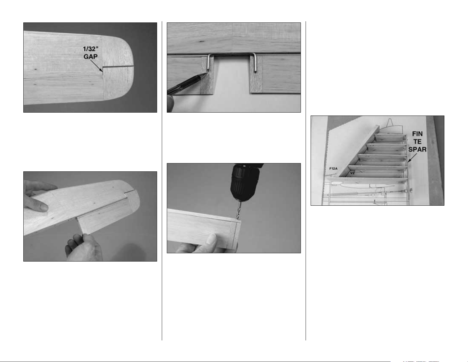
❏❏9. Test fit the elevator to the stab with the
hinges. Shift the elevator over to create a 1/32" gap
between the elevator tip and the end of the stab at
S-6. Sand the elevator tip to match the stab tip.
❏❏10. Shape the LE of the elevator to a “V” for
control throw. Make certain you can achieve 5/8" of
both up and down control throw as described in the
Control Throws section on page 58. Increase the
angle of the bevel if necessary.
❏ 11. Repeat steps 3 through 10 to finish the
other elevator.
❏ 12. With the elevators temporarily connected to
the stab with the hinges, center the elevator joiner
wire on the elevators where shown on the plan. Use
a ballpoint pen to mark the location of the joiner
wires on the elevator root blocks.
❏ 13. Drill 1/8" holes and cut grooves in both
elevators to accommodate the joiner wire. Hint: Use
a 1/8" brass tube sharpened on one end to cut the
grooves in the LE.
❏ 14. Test fit the elevators to the stab with the joiner
wire. Make certain both elevators are parallel. If
necessary, bend one of the “arms” of the joiner wire
to align the elevators with each other. Note: If you
found it necessary to bend the wire, it must be
inserted into the elevators the same way when it’s
time to glue it in.
Build the fin
❏ 1. Cut the fin plan from the side view of the fuse
plan along the dashed lines. Place the fin plan over
your building board. The same as the stab, if you
work carefully there is no need to protect the plan
from glue.
Refer to this photo for the following two steps.
❏ 2. Just the same as the stab, hold the die-cut 3/32"
balsa fin ribs V-1 through V-5 over the plan with rib
jig sticks cut from two 1/4" x 1/4" x 24" balsa sticks.
Note that the widest part of each rib is the LE. Add
the die-cut 1/8" balsa fin TE spar and align it over
the plan. Glue the ribs to the fin TE spar.
❏ 3. Sand the LE of the fin ribs to the angle of the
LE on the plan. Cut the fin LE from the 3/8" x 1-3/4"
x 12" balsa stick. Glue the fin LE to the front of the
ribs. Trim the left side of the fin LE to within 1/8" of
the upward facing (left side) of the ribs.
-15-
Page 16
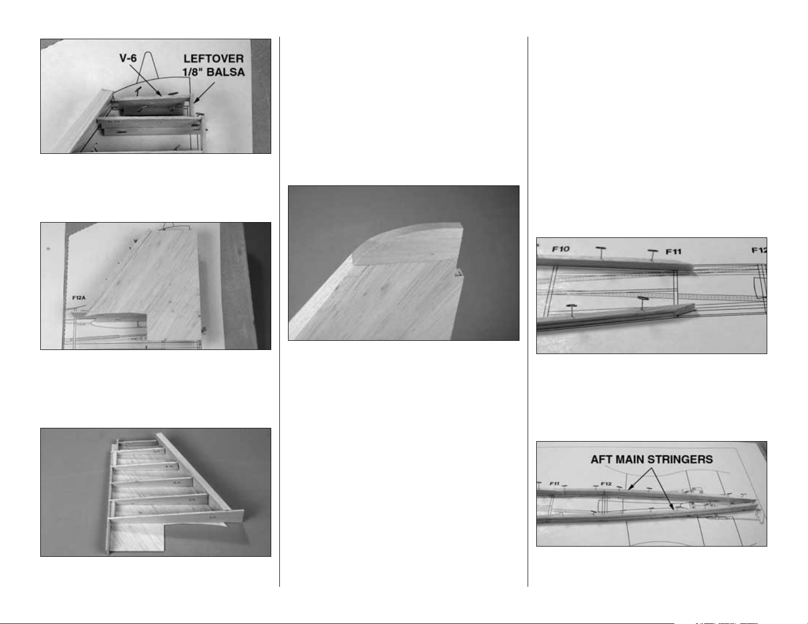
❏ 4. Add the die-cut balsa rib V-6 and the top of the
fin TE spar cut from leftover 1/8" balsa. Use a
builder’s square to make sure V-6 is perpendicular to
the building board.
❏ 5. Sand left side of the fin TE spar even with the
ribs. Use the pattern provided on the plan to make
two fin skins from the 1/16" sheeting leftover from
the stab. Glue one of the fin skins to the left side of
the fin.
❏ 6. After the glue has hardened, remove the fin
from the building board. Trim the jig tabs from the
right side of the fin ribs. Cut two fin hinge blocks
from the same 1/4" x 3/8" stick used for the stab and
elevator hinge blocks, then glue the hinge blocks to
the fin TE spar where shown.
❏ 7. Sheet the right side of the fin. Sand the fin
sheeting even with the fin tip and TE spar, then sand
the fin LE even with the sheeting. Do not round the
LE of the fin until instructed to do so.
❏ 8. Glue the 11/16" x 1-3/16" x 3-3/8" balsa fin tip
to the fin. Shape the tip to match the fin, but do not
round until instructed to do so (after the rudder is
completed).
This is all that can be done on the fin for now, until
the top of the fuse is built. The rudder is built directly
onto the fin when the fuse is near completion. So
now, it’s time to build the fuse!
BUILD THE FUSE
Frame the fuse top
Note: The formers that have part names stamped
on them are stamped with only the necessary
portion of their names (some formers are too
small to have a name stamped on them). For
example, former F-2A is stamped “2A”. As noted
earlier in the manual, refer to the die drawing
pages to identify the parts correctly.
❏ 1. Cut the top view of the fuse plan from the fuse
plan sheet. Place it over your building board covered
with Great Planes Plan Protector or wax paper.
❏ 2. Cut the forward main stringers from two 3/16"
x 3/8" x 48" grooved balsa sticks. Note the bevel that
must be cut on the aft end of the stringers at F-11.
It’s okay to cut the stringers an inch or so longer than
required so the excess extends forward of F-1. Pin
both stringers to the plan.
Refer to this photo for the next two steps.
❏ 3. Cut the aft main stringers from the remaining
3/16" x 3/8" x 48" grooved balsa stick. Be certain to cut
-16-
Page 17
the bevel on the front of the aft stringers to the correct
angle (if you cut the stringers a few inches longer than
required you will have enough material to make a few
adjustments until you get the angle just right).
❏ 4. Use a razor saw to cut partway through the
inside edges of the aft main stringers at F-12 so they
can make the bend. Pin the stringers into position
and glue them to the forward stringers. Add a few
drops of medium CA to the stringers where you cut
them at F-12.
Now for some of the fun stuff...
Note: All the following parts are die-cut 1/8" plywood
unless otherwise indicated.
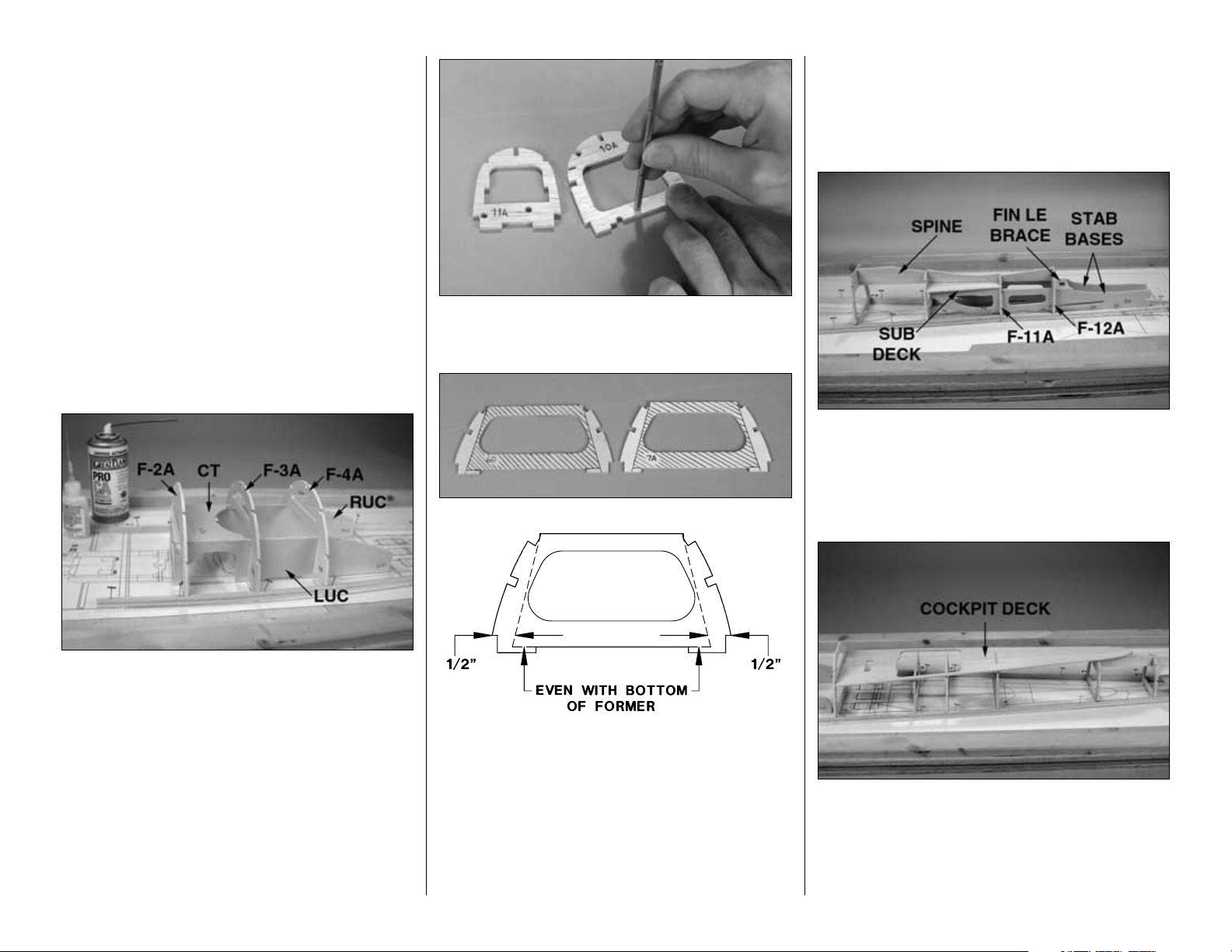
❏ 5. Without using any glue, join the parts of the
upper crutch assembly including the left and right
upper crutches (LUC, RUC), the crutch top (CT)
and F- 2A, F-3A and F-4A. Fit the assembly to the
main stringers over their location on the plan.
❏ 6. Glue the assembly together and to the main
stringers. Use a small builder’s square to make
certain the formers are perpendicular to the building
board. Note: Don’t worry about glue joints you can’t
reach while the fuse top is pinned to the building
board. We’ll remind you to reinforce them later.
❏ 7. Use a 3/16" brass tube sharpened at the end to
cut holes centered over the punchmarks in die-cut
1/8" balsa formers F-11A and F-10A.
❏ 8. If you are going to install the optional Top Flite
Scale Cockpit kit, use a straightedge and a ballpoint
pen to mark the cut-out lines on both die-cut 1/8"
plywood formers F-6D and F-7A as shown. The
shaded portions shown in the photo will be removed
later to accommodate the cockpit kit. Cut partway
through the formers, so they will be easier to cutout
after they are glued into position.
❏ 9. Glue formers F-5A through F-10A to the main
stringers over their location on the plan. Make certain
the formers are facing forward and use a builder’s
square to hold the formers perpendicular while
gluing them in place.
❏ 10. Assemble the stab base assembly at the back
of the fuselage with both stab bases (SB), the fin
LE brace, the die-cut 1/8" balsa formers F-11A & F12A, the die-cut 3/32" balsa sub deck and the die-
cut 1/8" balsa spine. Glue the pieces into position.
❏ 11. Glue together both halves of the die-cut 1/8"
balsa cockpit deck so the notches align. Sand the
pieces flat and even. If you are going to install the
scale cockpit interior, cut the deck along the partially
embossed lines and remove that section. Fit, then
glue the cockpit deck into position.
-17-
Page 18
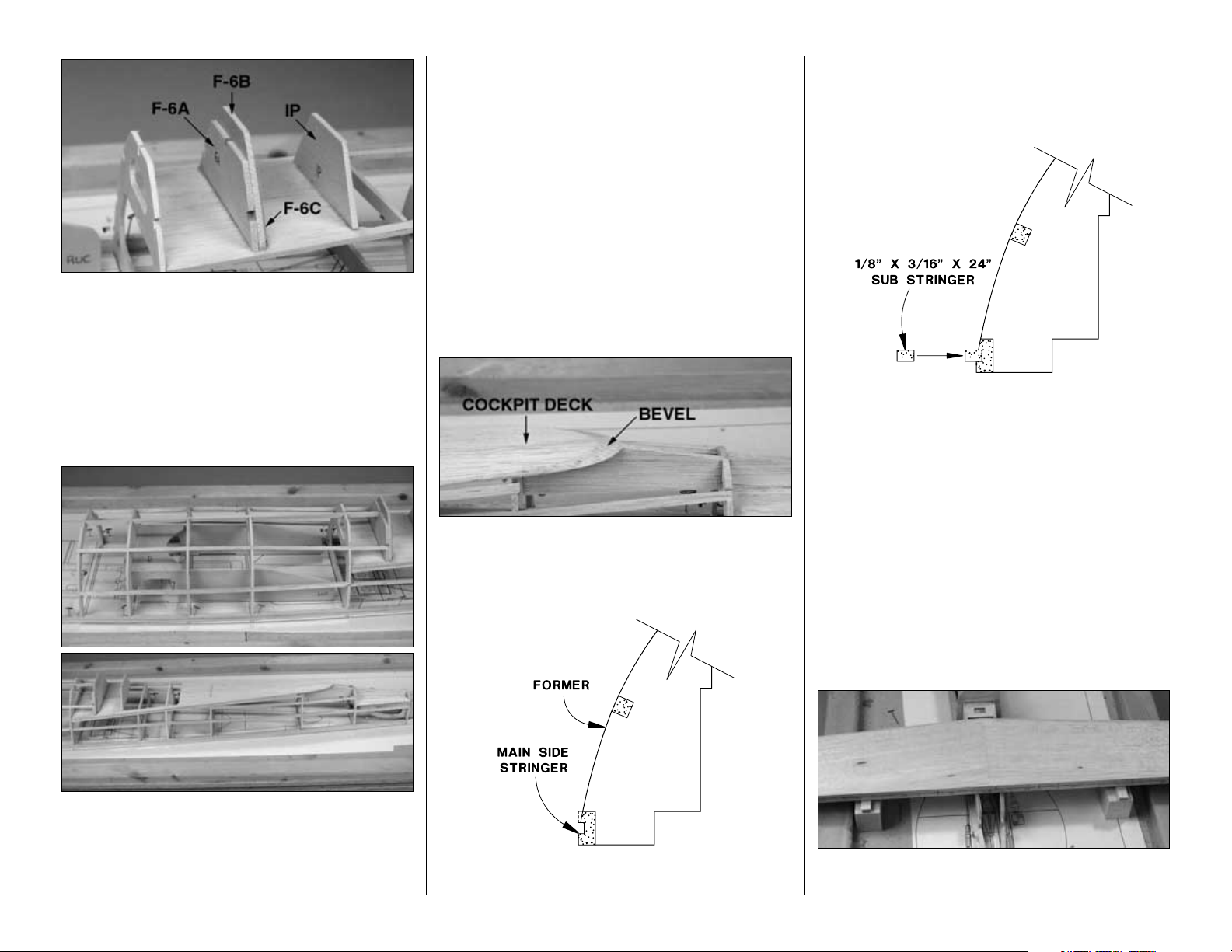
❏ 12. Glue together die-cut 1/8" balsa formers F-6A,
F-6B and F-6C, then glue them into the notch in the
cockpit deck. Glue the die-cut 1/8" balsa instrument
panel (IP) to the cockpit deck. Note that the
instrument panel and the F-6 assembly are
perpendicular to the building board, not to the
cockpit deck.
Now for the real fun part...
❏ 13. Use a total of seven 3/16" x 3/16" x 30" balsa
sticks for the stringers in the top half of the fuselage.
Without using any glue, start by fitting two stringers
into the top three notches of F-1 to F-6D (you’ll have
about a half of a stringer leftover). Next, fit two more
stringers into the notches of F-5A to F-9A
(immediately under the cockpit deck) on both sides
of the fuse (you’ll have two half-stringers leftover).
Then, fit the two leftover pieces into the notches of F8A to F-10A on both sides of the fuse. And finally, fit
three more stringers into the notches of F-1 to F-11A
on both sides of the fuse. They will have to be spliced
together at the notch in F-5A. Add former F-1A to the
assembly as you are fitting the stringers to the front
of the fuse.
❏ 14. After the stringers and former F-1A have been
fitted, glue them into position. Use a builder’s square
to make certain F-1A is perpendicular to the
building board.
❏ 15. Bevel the edges of the cockpit deck to match
the shape of the fuselage and the angle of the spine.
Sand all of the stringers and the sub deck even with
the formers.
❏ 16. Temporarily remove the T-pins from the main
stringers and take the fuse top off the building board.
Sand the main stringers to match the angle of the
formers. Replace the fuse top on the building board,
holding it down with T-pins.
❏ 17. Glue the five 1/8" x 3/16" x 24" sub stringers
into the groove of the main stringers. Make sure
none of the T-pins are protruding in the groove which
would interfere with the fit of the sub stringers.
Before we can sheet the fuse top, the stab and fin
must be glued into position.
Mount the stab and fin
❏
1. Position the stab on the stab base. Taking
careful measurements, make certain the stab is
centered, side-to-side, on the stab bases. Place a
weight on top of the stab to hold it down.
❏ 2. Measure the distance from the bottom of the
stab at both tips down to the building board. If the
-18-
Page 19
distances are not equal (if the stab is not level),
lightly trim the stab bases until you can get the stab
level. Use caution not to change the incidence
angle of the stab. If the stab is not exactly level, but
it’s close, sometimes all it takes is shifting the weight
slightly. Hint: Use balsa blocks of equal thickness to
level the stab. If you do this, make certain the stab is
fully contacting the stab bases.
❏ 3. Stick a T-pin into the center fuse stringer above
F-1. Tie a small loop in one end of a 50" piece of nonelastic line such as monofilament or Kevlar fishing
line. Slip the loop over the T-pin. Fold a piece of
masking tape over the string near the other end and
draw an arrow on it. Slide the tape along the string
and align the arrow with one end of the stab as
shown in the photo. Swing the string over to the
same position on the other side of the stab. Shift the
stab and slide the tape along the string until the
arrow aligns with both sides of the stab. The stab
must remain level and centered during this process.
❏ 4. Mark the stab where it aligns with the fuse so it
can be realigned after you take it off.
❏ 5. Remove the stab. Mix up a batch of 30-minute
epoxy. For additional strength, add Great Planes
Milled Fiberglass (GMR6165). Apply epoxy to the
stab bases and to the bottom of the stab where it
contacts the saddles. Reposition the stab and place
weights on top of it to hold it down. Confirm stab
alignment with the pin and string. Wipe away excess
epoxy and do not disturb the model until the epoxy
has fully hardened.
Refer to this photo for the following three steps.
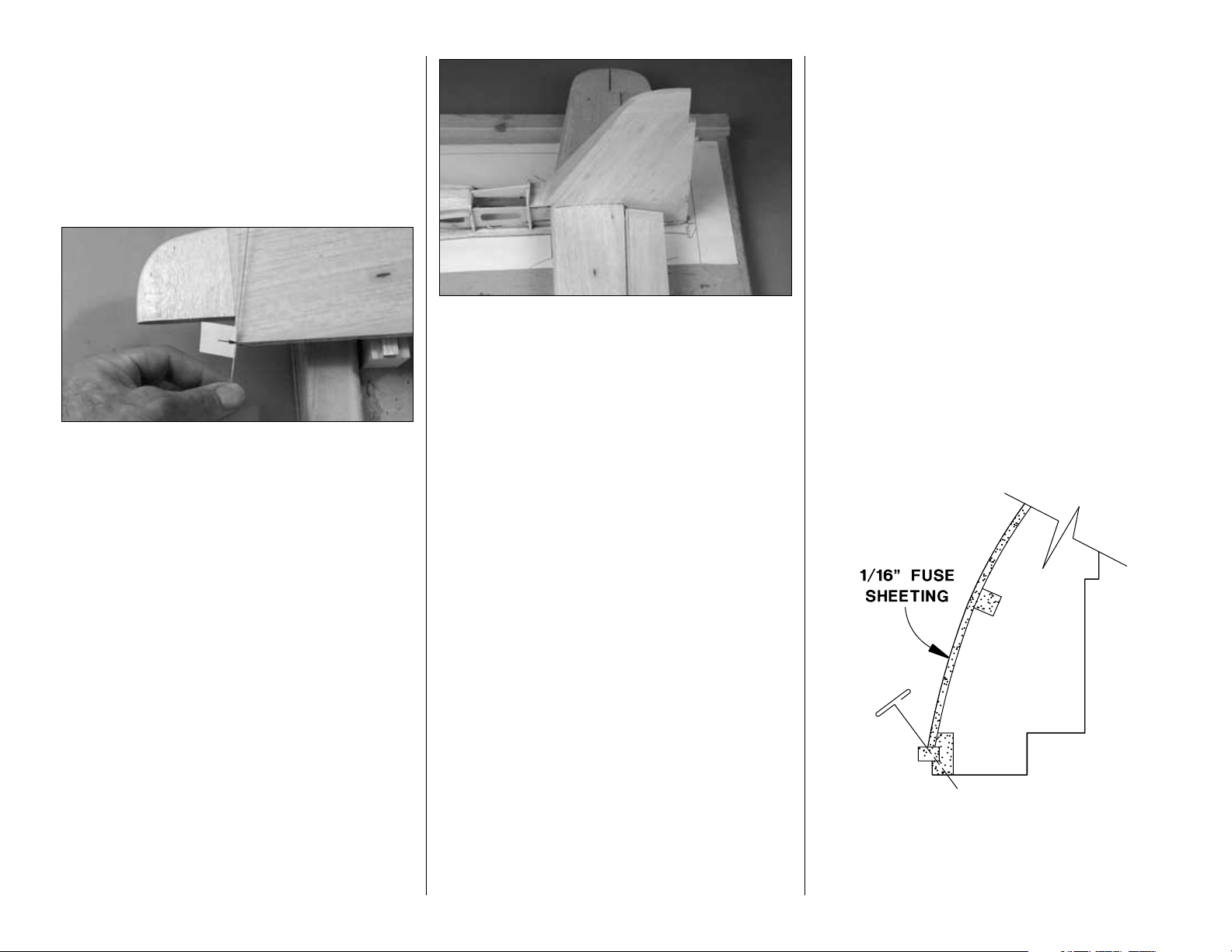
❏ 6. Use the “T-pin and straightedge” technique to
mark a centerline down the TE of the fin. After the
epoxy from the stab has fully hardened, test fit the fin
to the stab and fuse. Use a builder’s square placed
along the centerline you marked on the fin TE to
make sure the fin is vertical. Trim the fin sheeting
where necessary for a good fit to the top of the stab
and the sub stringers.
❏ 7. Temporarily join the elevators to the stab with
the elevator joiner wire and the hinges. Cut round
notches in the fin sheeting to accommodate the
elevator joiner wire.
❏ 8. With the elevator joiner wire in position, glue
the fin into position with 30-minute epoxy. Before the
epoxy cures, make certain the fin is vertical and the
front of rib V-1 is centered on F-12. Do not build up a
fillet of epoxy between the fin sheeting and the stab.
Sheet the top of the fuse
By now you’ve noticed that the Focke-Wulf fuselage
has some interesting lines and curves. Unlike many
other warbirds that have either a round fuselage
(such as a Corsair) or a “slab-sided” fuselage (such
as a Mustang), the Focke-Wulf fuse features a
mixture of irregular curves and converging angles.
While this doesn’t necessarily make sheeting the
fuselage difficult, careful thought and planning were
required during the construction of our prototype to
determine a procedure that modelers could
duplicate. Blocks are used in areas where it would be
too difficult to sheet. If you are an expert at sheeting
models, or if you prefer to do it a different way, you
could venture off. For most modelers, we
recommend that you carefully follow these
instructions to end up with a fuselage that replicates
the lines of the Focke-Wulf.
❏ 1. One at a time, remove the T-pins from the main
stringer and reinsert them as shown in the sketch.
This way, the pins won’t be concealed under the
sheeting when it’s time to take the fuse off the
building board.
-19-
Page 20
This is really the only “tricky” piece of sheeting.
We’ve provided three photos to make sure you
can do it correctly.
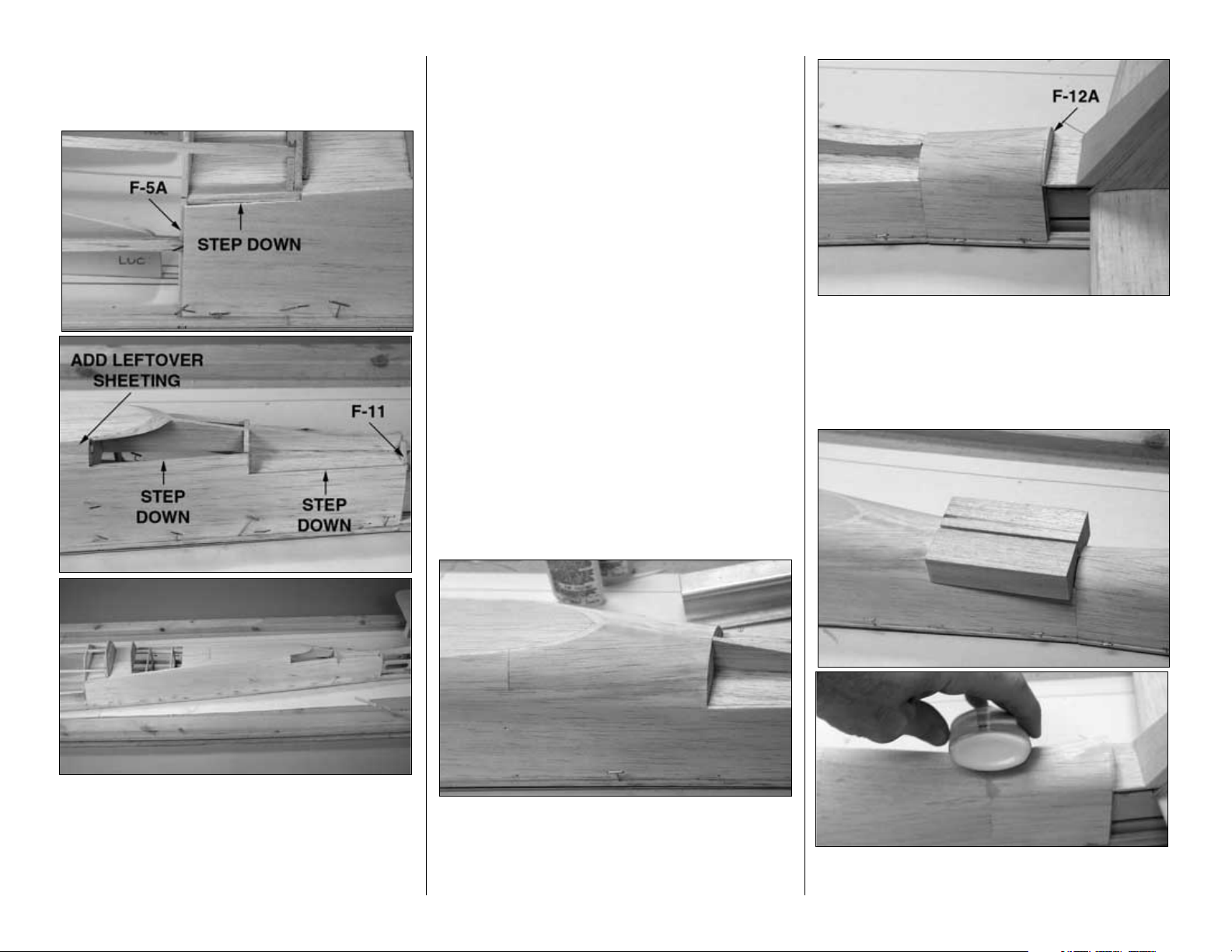
❏ 2. Cut 4" from a 1/16" x 3" x 30" balsa sheet. Set
the 4" piece aside for use later. Cut the larger portion
of the sheet to fit the fuse as shown. The sheet
extends from the middle of F-5A to the middle of
F-11. Cut the top edge of the sheet slightly higher
than the cockpit deck (to be sanded flush later). The
bottom of the sheet rests against the sub stringer. A
piece of leftover 1/16" sheeting will have to be added
to the top of the sheet where it cannot reach the
cockpit deck. Note that the aft edge of the fuse sheet
“steps down” twice; once to the middle of the stringer
and once more to the top edge of the sub deck. The
front of the sheet also has a step down to the stringer
at F-6B. Once you have cut the sheet to fit, use a
ballpoint pen to trace its outline onto another sheet
to make a pattern for the right side.
❏ 3. Glue the sheet into position. We prefer to use
aliphatic resin to glue the sheet to the main and sub
stringers holding it in place with T-pins. After the glue
dries, wet the sheet with water or window cleaner (it
shouldn’t need much, it’s only 1/16" thick), then use
medium CA to glue it to the rest of the stringers,
formers, sub deck and cockpit deck. Fit, then trim
and glue the other sheet to the right side (setting
aside another 4" portion of the sheet as you did in
the previous step). Hint: When wetting the sheeting,
use a paint brush to avoid getting over-spray on the
rest of the structure.
❏ 4. Cut two 5" pieces from another 1/16" x 3" x 30"
balsa sheet. Save the remaining 20" sheet for use
later. Use the 5" pieces to sheet both sides of the
fuse aft of the cockpit deck between F-9A and F-10A
as shown in the photo.
❏ 5. Sheet both sides of the fuse between F-11A
and F-12A using both of the 4" pieces you cut in step
2 and 3. You’ll have to add a strip of leftover sheeting
to the bottom of the 4" sheet so it will reach all the
way up to the spine. Note that the aft edge of the
sheet extends to the middle of F-12A.
❏ 6. Glue both 1" x 1-3/16" x 4-1/8" balsa aft turtle
deck blocks to the sub deck and the spine. Shape
-20-
Page 21

the blocks to match the shape of the sheeting and
the spine. Hint: After carving the block to the
approximate shape, wrap a piece of Great Planes
80-grit adhesive back sandpaper around a glue
bottle for a curved sander.
❏ 7. Sheet both sides of the front of the fuse as
shown using one 1/16" x 4" x 30" balsa sheet.
❏ 8. Cut 8" from the 20" sheet leftover from step 4.
Use the 8" piece to sheet the top of the fuse from
F-6B to a point 7/8" ahead of F-4A. Save the
remaining 12" piece to sheet the fuse under the stab.
Sheet the rest of the front of the fuse using a 1/16" x
3" x 30" balsa sheet. Note: Don’t be too concerned
about the appearance of the sheeting from F-6B to
F-4A. This area of the fuse will be concealed by the
molded ABS machine gun cover.
❏ 9. Sheet the instrument panel from F-6B to the IP
with leftover 1/16" balsa.
❏ 10. Remove all the T-pins and take the fuse top off
the building board. Trim the sheeting and stringers
even with F-1A. Look for glue joints you couldn’t get
to while the fuse top was pinned to the building board
or ones that don’t look strong enough and reinforce
them with CA.
❏ 11. Use the 12" piece of 1/16" sheeting leftover from
step 8 to sheet both sides of the fuse under the stab.
❏ 12. Use the pattern provided on the plan to shape
the 1-1/8" x 1-7/8" x 3" balsa fin fillet block as
shown in the photo.
❏ 13. Glue the fin fillet block into position. Carve,
then sand the fin fillet block blending it to the fin and
the fuse. As you proceed, round the LE of the fin, but
-21-
Page 22

do not round the tip of the fin until instructed to do so.
Fill the gap between the fuse sheeting and the fin
fillet block with balsa filler.
Note: From some viewpoints, the aft end of the fuse
where it joins the fin features some “funny” angles.
Due to the added fuse section, this represents the
actual shape of the full-size Fw 190D. In truth, your
model probably looks better than the real one!
Hey,
they didn’t build ‘em pretty, they just had to get the
job done!
Build the fuse bottom
❏ 1. Reinforce the glue joint inside the fuse between
the bottom of the stab and the stab bases with a
small fillet of 30-minute epoxy. For additional
strength, mix in milled glass fibers.
❏ 2. Test fit your servos in the die-cut 1/8" plywood
servo tray. If necessary, make adjustments to the tray
so your servos will fit. Glue the two doublers to the
bottom of the servo tray for the servo screws. Drill a
5/16" hole through the punchmarks in the laser-cut 1/8"
ply former F-4C, then glue it to the front of F-4B so the
holes align. Remove glue from inside the holes before
it hardens.
Do you enjoy puzzles? If you do, you’ll enjoy the next
few steps.
❏ 3. All of the parts in this step are die-cut 1/8"
plywood. Fit but do not glue the right and left lower
crutches (RLC, LLC), the crutch bottom (CB), one
of the firewall laminations F-1, the servo tray and
F-2B through F-8B. Inspect all joints for a good fit
and make adjustments where necessary.
❏ 4. Once you are satisfied with the fit of all the
parts, permanently glue everything except for F-1B
into position.
❏ 5. Cut elevator and rudder pushrod exit slots in the
aft end of the fuse sheeting. Hint: Use a 3/16" brass
tube sharpened on the end to cut the slots. Slide the
tube through the holes in the formers so the slots will
be in the correct position and at the correct angle.
❏ 6. Cut two 3/16" pushrod guide tubes to a length
of 29" and 31". Scuff the guide tubes with coarse
sandpaper so glue will adhere.
❏ 7. Install the tubes and glue them to F-11A with
CA and to the sheeting where they exit the fuse with
epoxy mixed with microballoons. The tubes will be
sanded even with the sheeting after the rest of the
fuse is sheeted.
❏ 8. Glue F-1B and F-9B through F-12B to the main
fuse stringers and to their respective formers. Glue a
small strip of leftover 1/8" plywood across the glue
joint between both sides of F-1A and F-1B.
-22-
Page 23

❏ 9. Cut ten 3/16" x 3/16" x 36" balsa stringers to the
correct length, then glue them into the notches in the
formers on the bottom of the fuse. Carefully view the
formers and remove any twist as you glue the
stringers to them. The stringers nearest the main
stringer will have to be spliced together at F-5. Trim
the ends of the stringers even with F-1, F-4, F-8 and
F-12.
❏ 10. Sand the formers and stringers, blending them
together.
Sheet the bottom of the fuse
❏ 1. Sheet the right side of the fuse from F-1 to F-9
with a 1/16" x 3" x 36" balsa sheet. The aft end of the
sheet must align with the middle of F-9. The same as
you did when you glued the first piece of sheeting to
the top half of the fuse, we recommend you first glue
the sheet to the main stringer, allow the glue to dry,
then wet the sheet and glue it to the rest of the
stringers and formers. Trim the sheeting even with
the lower fuse crutches.
❏ 2. If you notice that, after it has been glued into
place, the sheeting bows noticeably outward in the
wing saddle area between F-4 and F-7 (it most likely
will), first allow the water you applied for bending to
fully dry. This may take a few hours or even
overnight. If the sheeting is still bowed outward, cut
that part of sheeting from the fuse and replace it with
a separate piece of leftover 1/16" sheeting.
❏ 3. Sheet the left side of the fuse the same way.
❏ 4. Sheet both sides of the fuse from F-9 to F-11
with one 1/16" x 3" x 30" balsa sheet.
❏ 5. Glue the pushrod guide tubes to F-9 & F-10.
❏ 6. Sheet the bottom of the fuse from F-8 to F-11
with two 1/16" x 3" x 30" balsa sheets.
-23-
Page 24

❏ 7. Sheet the rest of the fuse bottom from F-4 to
F-1 with 1/16" sheeting left over from the preceding
steps. Do this in three strips to distribute the
compound bending that will be required of each sheet.
❏ 8. Sheet the last section of the bottom of the fuse
from F-11 to F-12 using leftover 1/16" balsa sheeting.
❏ 9. Sand the fuse sheeting even with F-1, F-8 and
F-12.
Mount the tail gear
❏ 1. Cut the aft alignment post off the nylon tail
gear bracket.
❏ 2. Use pliers to flatten 1/4" of one end of the 1/8"
x 5/8" brass tube. Slide the tube onto the tail gear
wire and place the assembly over the top view of the
plan to make sure it is the correct length. Silver
solder the brass tube to the tail gear wire. Drill a
1/16" hole through the end of the brass tube where
shown on the plan. From now on this portion of the
tail gear wire will be referred to as the
steering arm
.
❏ 3. Drill a 1/16" hole through the two front
punchmarks and a 1/8" hole through the aft
punchmark in the die-cut 1/8" plywood tail gear
mount plate. Make a 1/8" x 1/4" x 3/4" doubler for
the screws that hold the tail gear mount and glue it
across the two forward holes in the plate. Temporarily
mount the tail gear mount to the tail gear mount plate
with two #2 x 3/8" screws (you can see the assembly
in the photo at step 6).
❏ 4. Use a tissue dampened with denatured alcohol
or a similar solvent to remove the oil coating from
one of the .074" X 36" pushrod wires. Cut twelve 3/8"
long bushings from the 6" white inner pushrod tube,
then slide them onto the wire and space them as
shown on the tail gear pushrod on the fuse plan.
Make sure you position the bushings at the ends of
the wire so they will not protrude from the rudder
guide tube, or the controls could become jammed
during flight. If the bushings slide onto the wires
easily, secure them with a drop of thin CA. Allow the
CA to fully harden before proceeding. If the bushings
are impossible to slide on, cut them to a shorter
length to provide less resistance.
❏ 5. Slide the pushrod wire with the bushings on it
into the rudder pushrod guide tube on the left side of
the fuselage. Place a straightedge on the fuse and
align it with the wire. Use a ballpoint pen to mark a
line along the straightedge.
-24-
Page 25

Refer to this photo for the following three steps.
❏ 6. Thread a nylon dual-ended ball link onto the
wire pushrod, then snap in a threaded ball. Reinsert
the pushrod into the guide tube. Neatly cut an exit
slot in the fuse sheeting to accommodate the
steering arm. The center of the slot should be 3/16"
below the line you drew on the fuse sheeting.
❏ 7. Without using any glue, position the tail gear
mounting plate on the fuse. Temporarily mount the
threaded ball (that you snapped into the ball link on
the pushrod) to the steering arm with an 0-80 nut.
❏ 8. Move the pushrod back and forth to see if the
slot is long enough for the steering arm. Lengthen
the exit slot if necessary.
❏ 9. Remove the tail gear mount from the tail gear
mounting plate. Permanently glue the mount plate to
the main stringers and F-12. Glue a couple of
leftover 1/8" balsa strips to the main stringers behind
the tail gear mount plate to take up the empty space.
❏ 10.Glue both shaped 1/4" balsa aft fuse side blocks
to F-12 and the bottom of the tail gear mount plate.
❏ 11. Permanently glue the 3/8" x 2" x 4-3/4"
forward fuse bottom block to F-12 and the aft fuse
side blocks. Tack glue the 3/8" x 1-3/8" x 4" x aft
fuse bottom block to the aft fuse side blocks so it
can be removed after it is shaped. After the fuse
bottom has been final shaped, the aft fuse bottom
block will be removed for installation of the tail gear.
Glue a strip of leftover balsa into the groove on the
main stringer on both sides of the fuse.
❏ 12. Remove the tail gear pushrod. Sand the guide
tubes on both sides of the fuse even with the fuse
sides. Use a razor plane or a carving knife followed
by sanding to shape the blocks to match the fuse.
❏ 13. Pop off the aft fuse bottom block that you tack
glued earlier. Permanently mount the tail gear mount
to the tail gear mount plate with two #2 x 3/8" screws.
Add a few drops of CA so the screws will never
loosen. Add a drop of thread locking cement to the
set screw that holds the wheel collar. Center the
steering arm, height-wise, in the slot, then tighten
the set screw. Add a drop of household oil to the tail
gear wire where it enters the nylon bearing tube (so
any glue that gets into the area will not adhere and
bind the steering).
❏ 14. Cut the aft fuse bottom block into two pieces. Cut
a half-round hole in each half that aligns with the tail
gear wire. Permanently glue the blocks into position.
-25-
Page 26

❏ 15. Glue the die-cut 1/8" balsa fin TE to the fin TE
spar. Sand the fin TE to blend in with the fin and the
bottom of the fuse.
Now the fuse is far enough along that the rudder can be
built. For a perfect match, it’s built directly onto the fin.
Build the rudder
❏
1. Glue together both die-cut 1/8" balsa parts of
the rudder core.
❏ 2. Place the rudder core over the rudder plan. Use
a ballpoint pen to mark the locations of the rudder
ribs on both sides of the rudder core.
Refer to this photo for the following three steps.
❏ 3. Make both rudder tip blocks from the 1/4" x 1-
7/8" x 6" balsa sheet and make both rudder base
blocks from the 3/8" x 2-1/8" x 7" balsa sheet. Glue
the blocks to the rudder core, then shape them to
match the rudder core, but do not round them yet.
❏ 4. Cut the rudder LE from the 1/4" x 7/8" x 12"
balsa stick, then tack glue it to the TE of the fin.
❏ 5. Securely glue the rudder core and the tip and
base blocks to the rudder LE that is tack glued to the
fin. Be certain the rudder is centered. Be careful not
to inadvertently glue the rudder to the fin. Hint: Use
a rubber band to hold the rudder to the fin while you
center it up for gluing it into position.
❏ 6. Start with a razor plane followed with a bar
sander to carefully blend the rudder tip blocks to the
fin, then round the fin tip and rudder tip to match
each other. Round the rudder base blocks to match
the bottom of the fuse.
❏ 7. Cut the rudder ribs from the 3/32" x 5/16" x 30"
balsa stick, then glue them to the rudder. Shape the
ribs to match the rudder.
❏ 8. Carefully break the rudder free from the fin. Cut
the rudder hinge blocks from strips of leftover 1/8"
balsa and glue them to both sides of the rudder core.
The same as you did for the elevators, draw a
centerline on the rudder LE and the fin TE and cut
slots for the hinges. Bevel the LE of the rudder and
round the balance tab to clear the fin. Test fit the
rudder to the fin. Make certain you can achieve 1-1/4"
of right and left control throw.
While we’re working on the rudder and the back of
the fuse, let’s go ahead and mount the control horns.
Do the rudder first.
❏ 9. Install the tail gear pushrod and temporarily
connect it to the steering arm on the tail gear the
same as you did before. Connect the rudder to the
steering arm using the hardware shown on the plan
and in the photo. Use silver solder to join the .074" x
4" pushrod to the threaded coupler.
-26-
Page 27

❏ 10. Adjust the metal clevis so the rudder will be
centered when the tail gear is centered.
❏ 11. After you mount the control horn to the rudder,
remove the control horn. Use a pin to poke several
holes in the balsa in the area of the control horn.
Apply a few drops of thin CA to the screw holes and
to the area of the pinholes to harden the balsa for the
control horn.
❏ 12. The same as you did the tail gear pushrod,
prepare the elevator pushrod from a .074" x 36"
threaded one end pushrod with 3/8" bushings cut
from the inner pushrod tube. Connect the pushrod to
a nylon clevis and a large nylon control horn. Mount
the control horn to the elevator with two 2-56 x 5/8"
screws and the nylon mount plate on the top of the
elevator (see the elevator cross-section on the plan).
❏ 13. Remove the elevator horn. The same as the
rudder, poke several holes in the rudder base block
in the area of the horn and apply a few drops of thin
CA. Sand smooth, then temporarily mount the
elevator horn.
Finish the turtle deck
❏ 1. Glue together both shaped 1-1/2" balsa
forward turtle deck blocks.
❏ 2. Cut the forward turtle deck pattern from the
plan. Use a ballpoint pen to trace its outline onto the
forward turtle deck block. Draw a centerline down the
top of the block as well.
❏ 3. Glue the forward turtle deck block to the top of
the cockpit deck. Use a razor plane followed by a bar
sander to shape the block to match the outline you
drew on the front. The block blends to the fuse in the
rear. It’s a little tricky to carve, because the shape of
the fuse changes angles at the base of the block as
shown in the sketch. Don’t final shape the forward
turtle deck block until you fit it to the canopy in the
following steps.
❏ 4. Use curved-tip scissors to trim the molded ABS
machine gun cover along the molded-in cutlines. The
cutlines are most easily seen from the inside. True the
edges with a bar sander and 80-grit sandpaper.
Temporarily hold the machine gun cover to the fuse with
masking tape. Note that the aft edge of the machine
gun cover aligns with the middle of former F-6B.
❏ 5. Trim the clear molded canopy along the molded-
in cutlines. True the edges with a bar sander and 80grit sandpaper. Test-fit the canopy to the fuse. The
front edges of the canopy should join the aft edge of
the machine gun cover. Trim both pieces as
necessary for a good fit.
-27-
Page 28

❏ 6. Trim the bottom edges of the canopy so that it
overlaps the fuse by approximately 3/16" to provide
a gluing surface.
❏ 7. Once you have achieved a good fit between the
canopy and the fuse and between the canopy and
the machine gun cover, finish shaping the forward
turtle deck block to fit the canopy. Use balsa filler to
blend the turtle deck block to the fuse at the seam
where they join.
Mount the engine
❏
1. Use thick CA or epoxy to glue together the diecut 1/8" plywood pieces FW-1, FW-2 and FW-3 that
make up the firewall. If the individual pieces are
twisted, clamp them to a flat table or piece of wood
covered with wax paper. Be certain they stay in
alignment. If the pieces are twisted, simply clamping
them together may not cancel the twist.
❏ 2. Drill four 7/32" holes through the punchmarks in
the firewall. Use a hammer to lightly tap four 8-32
blind nuts into the holes in the back of the firewall.
Permanently glue the blind nuts into the firewall with
a few drops of thin CA.
❏ 3. Cut a 2-3/4" long forward tank mount tab from
the 1/4" x 3/8" x 36" basswood stick. Save the
remainder of this basswood stick for the servo hatch
rails in the wing. Glue the tab to the back of the
firewall 1/8" above the bottom edge.
❏ 4. Mount the Great Planes .60-1.20 Adjustable
Engine Mount to the firewall with four 8-32 x 1-1/4"
socket head cap screws and #8 lock washers and
flat washers (note that the engine is mounted
inverted). Leave the screws loose enough to slide
the halves of the mount in and out. Adjust the mount
so it fits your engine, then tighten the screws and
temporarily clamp the engine to the mount with the
back plate of a 3" spinner 6-1/4" from the firewall.
Note: Some spinners have a flat back plate and
some spinners have an in-set back plate. Take this
into account when mounting your engine. It may be a
good idea to actually have your spinner back plate
mounted on your engine for this step.
❏ 5. Use a Great Planes Dead Center Hole Locator
(GPMR8130) to mark the locations of the holes in the
mount for mounting your engine. Remove the engine,
then drill four #29 (or 9/64") holes at the marks. Tap 832 threads into the holes. Mount the engine to the
mount with four 8-32 x 1" screws and washers.
Remove the engine mount from the firewall.
❏ 6. If you have your fuel tank on hand, drill 1/4" (or
15/64" for a perfect fit) holes through the firewall to
pass the fuel tubing. If you don’t have your tank yet
or plan a mounting method other than that shown in
the manual, you may wait until later to drill the holes.
❏ 7. Test fit, then glue the firewall to the fuse with 30-
minute epoxy. Add Great Planes Milled Glass Fibers
for additional strength. Make certain the firewall is
oriented correctly, so the engine will be mounted as
you intended (inverted if you’ve followed the
instructions and plan).
That’s about all that can be done on the fuse until we
have a wing, so...let’s build the wing.
BUILD THE WING
Preparation
Reminder: If you’re installing retracts, take the air
lines out of the package and hang them somewhere
in your workshop. This will straighten the lines and
make them easier to install when it’s time.
Each wing panel is built right-side up over the wing
panel plan. The manual shows photos of the right
wing panel, so start building the right wing panel first.
❏❏1. Cut the right (or left, if this is your second
wing panel) wing plan from the wing plan sheet and
place it over your building board. Cover the plan with
Great Planes Plan Protector or wax paper.
-28-
Page 29

Perform steps R5 through R8 only if you are
building your wing with RETRACTABLE landing
gear. An “R” placed in front of each step notes
that it is for RETRACTABLE landing gear ONLY.
❏❏R5. Use thick CA or epoxy to glue two die-cut
1/16" plywood rib doublers W-4AR to both sides of
the die-cut 3/32" balsa wing rib W-4. Glue two diecut 1/16" plywood rib doublers W-5AR to both sides
of the die-cut 3/32" balsa wing rib W-5.
❏❏R6. Use a hobby knife to remove the shaded
portion of balsa shown in the photo.
❏ R7. Repeat the previous two steps to make
another set of ribs for the other wing panel.
❏ R8. Use a 5/32" brass tube sharpened on the end
to cut two holes for the air lines in each set of ribs
W-1, W-2 and W-3. The holes should be located near
the top of the ribs and the aft edge of the holes
should be located 1/16" forward of the top and
bottom main spars as shown in the sketch.The holes
in both W-1’s should align with each other.
❏ 9. Glue one of the die-cut 1/8" plywood rib
doublers W-1A to one side of the die-cut 3/32" balsa
rib W-1. Glue the other W-1A to the other side of the
other W-1. Be certain you are making a right and a
left. If you’re installing retracts, drill the holes through
the doublers for the air lines.
❏ 10. Use a hobby knife and a straightedge to lightly
score both W-1’s as shown. When it’s time to join the
wing panels, this section of balsa will be removed to
accommodate the wing joiners.
Perform this step only if you are building flaps.
❏ 11. Use a straightedge to cut partway through ribs
W-3 through W-6 (and W-6B) from the aft notch to
the tip of the rib. This section of rib will be removed
when it’s time to build the flaps.
❏❏F2. Use thick CA or epoxy to glue two die-
cut 1/16" plywood rib doublers W-4AF to both
sides of the die-cut 3/32" balsa wing rib W-4.
Glue two die-cut 1/16" plywood rib doublers W-
5AF to both sides of the die-cut 3/32" balsa wing
rib W-5.
❏❏F3. Use a hobby knife to remove the shaded
portion of balsa shown in the photo.
❏ F4. Repeat the previous two steps to make
another set of ribs for the other wing panel.
Perform steps F2 through F4 only if you are
building your wing with FIXED landing gear.
An “F” placed in front of each step notes that
it is for FIXED landing gear ONLY.
-29-
Page 30

Frame the wing panel
Refer to this photo for the following two steps.
❏❏1. Without using any glue until instructed to
do so, join ribs W-2 through W-9 to the die-cut 1/8"
balsa spar web. Join the 1/4" x 3/8" x 30" basswood
top and bottom main spars, followed by the die-cut
1/8" balsa outer TE spar and the die-cut 1/8" balsa
aileron spar.
❏❏2. Join ribs W-10 and W-1 to the assembly. Make
certain the ends of the top and bottom spars extend
beyond W-1, so they can be trimmed flush later.
❏❏3. Place the assembly over the plan. Making
certain the parts are accurately aligned over the plan,
insert T-pins through the spar web to hold the bottom
spar and the spar web flat on the building board. Insert
T-pins through the TE spar (or use leftover rib jigs) to
hold the TE spar to the building board.
❏❏4. Join the die-cut 1/8" balsa inner TE spar to
the assembly and hold it down with jig sticks pinned
to the building board.
Now it’s time to glue!
❏❏5. Be sure that all the parts align with their
location on the plan, that the ribs are fully seated into
the notches of the outer TE spar and that the TE spar
is fully contacting the plan. Glue the spar web to the
top and bottom spars and to all ribs except W-1.
Glue the ribs to the outer TE spar and to the aileron
spar. Use a small builder’s square to make certain tip
rib W-10 is perpendicular to the building board (this
will align the wing tip blocks with the wing when it’s
time to glue them on).
Refer to this photo for the following two steps.
❏❏6. Insert strips of leftover 1/8" x 1/4" balsa
between the top and bottom main spars and rib W-1.
These will help support W-1 when a portion of it is
removed to accommodate the spar joiners.
❏❏7. Use the die-cut 1/8" plywood dihedral gauge
to hold W-1 at the correct angle, then glue it into
position. Don’t glue W-1 to the spar web. Just glue it
to the leftovers you glued in, in the above step and to
the inner TE spar.
Refer to this photo for the following three steps.
❏❏8. Cut the shaped 30" balsa leading edge to
the correct length to fit the wing from W-3 to W-10 as
shown on the plan. Glue the LE, centered heightwise, to the fronts of the ribs.
-30-
Page 31

❏❏9. Cut the remainder of the shaped LE to the
correct length, then glue it to ribs 2 and 3.
❏❏10. Cut the 1/2" x 1-1/4" x 7" center LE into two
3-1/2" pieces. Use the dihedral gauge to mark the
angle on one end of the center LE to match the angle
of W-1. Cut the center LE at the line you marked and
glue the center LE to the wing.
❏❏11. Add the die-cut 3/32" balsa rib tips W-2C,
W-6B and W-7B to the outer TE spar. While gluing
the ribs into position, use a straightedge to align
them with the other ribs on the wing.
❏❏12. Use a bar sander with 80-grit sandpaper to
sand the tops of the ribs and spars even.
Now the wing is ready for the top sheeting. But first,
you have to make the wing skins.
❏ 13. Glue together the wing skins the same as you
did the stab and fin skins. Start by making eight 6" x
30" balsa sheets from sixteen 1/16" x 3" x 30" balsa
sheets. (You can make all the skins in an
assembly-
line
fashion now, or make them as you need them.)
❏❏14. The top and bottom of both wing halves will
be sheeted with two of the 6" x 30" balsa sheets you
just made. The seam between the two pieces will be
centered over the main spars. Make a forward wing
skin for the top of the wing by trimming one of the 6"
x 30" sheets to fit between the LE and the middle of
the top spar. The grain direction is parallel with the
LE. The gap between the front of the skin and the LE
between ribs 1 and 3 (as seen in the following photo)
will be filled in later.
❏❏15. Take out T-pins that you will not be able to
get to after the sheeting is glued down.
❏❏16. Glue the forward wing skin into position. Our
preferred method is to first apply aliphatic resin to the
ribs, then to glue the sheet to the LE with thin CA.
Lay weights on top of the sheeting to hold it to the
ribs, then glue it to the main spar with thin CA.
❏❏17. Make an aft wing skin for the top of the
wing by trimming another 6" x 30" sheet to fit. The
grain is parallel with the outer TE spar. You’ll have to
trim a piece from the trailing edge of the sheet near
the tip, then glue it back onto the other end of the
sheet to make it wide enough. The aft skin ends in
the middle of the outer TE spar between rib W-6B
and rib W-2. This will create a “ledge” to support the
flap sheeting that will be added later. Glue the aft
wing skin into position. Do not glue the sheeting to
the inner TE spar and to rib 2 aft of the inner TE spar
(see the following photo).
❏❏18. Cut the sheeting from the wing from the
middle of the inner TE spar and the middle of rib W2 aft of the inner TE spar. This will create a ledge to
support the sheeting that will be added after the wing
panels are joined.
❏❏19. Make an aileron skin from 1/16" sheeting left
over from the top wing skins and glue it into position.
Sorry, the flap skin won’t be so simple...but it’s worth it.
-31-
Page 32

Refer to this sketch for the following seven steps.
❏❏20. Cut the 1/32" x 1" x 16" plywood sheet into
two 1/2" strips.
❏❏21. Cut a 1/2" x 16" strip and a 2-1/4" x 16" strip
from a 1/16" x 3" x 30" balsa sheet.
❏❏22. Laminate the 1/2" balsa strip to one of the
1/2" ply strips over a flat surface. You now have a
3/32" x 1/2" x 16" ply/balsa strip.
❏❏23. With the ply side down, glue one edge of the
ply/balsa strip to the edge of the 2-1/4" balsa strip.
This is now the top flap skin.
❏❏24. Sand the balsa side of the 1/2" x 3/32" portion
of the top flap skin to the same thickness as the rest of
of the top flap skin (which is 1/16" thick).
❏❏25. Trim the top flap skin to fit the wing from the
middle of W-2 to W-6B. The ply side goes down.Make
certain that the TE of the skin (the end with the 1/32"
ply strip) aligns with the TE of the flap on the plan.
❏❏26. Cut a 1/8" x 3/16" x 30" balsa stick to the same
length as the top flap skin, then glue it to the ply side
along the TE as shown in the sketch. Later, this will be
sanded to match the tapering angle of the wing.
❏❏27. Glue the top flap skin to the top of the wing.
❏❏28. Remove the wing panel from the building
board. Use leftover 1/16" balsa sheeting to fill in the
space between the forward skin and the LE. Look for
glue joints you’ve missed, or ones that could use a
little extra glue and reinforce them with CA. Apply a
bead of medium or thick CA where the sheeting
meets the LE inside the wing.
❏❏29. Trim the ends of the main spars close to the
ribs on both ends of the wing. Follow-up with a bar
sander with 80-grit sandpaper to sand the spars and
sheeting even with the ends of the wing. If you would
like to trim the top of the LE even with the sheeting,
you may do so at this time, but do not final shape the
LE until instructed to do so after the wing is sheeted
and both panels are joined. Trim the tabs off the
bottom of the outer and inner TE spars. Sand the
bottoms of the ribs even with the bottoms of the
spars to prepare the wing for the bottom sheeting.
When sanding the bottom of the wing, use the ends
of the ribs to guide your bar sander as you bevel the
top aileron skins down to 1/32" at the TE as shown in
the sketch.
-32-
Page 33

Fit the landing gear
Perform steps R1 through R12 only if installing
retractable landing gear. If installing fixed gear,
skip to step F13.
Refer to this photo for the following three steps.
❏❏R1. Test fit the 1/4" plywood forward and aft
landing gear rails in the slots in ribs W-4 and W-5.
If necessary, make adjustments to the notches or
remove glue bumps so the rails fit well.
❏❏R2. Mount a 3-3/4" wheel to your landing gear.
This model was designed to use CJM (Century Jet
Retracts) Focke-Wulf landing gear with Williams
Bros. #143 3-3/4" Smooth Contour Wheels
(WBRQ1143). These wheels have a narrow crosssection allowing the gear to fully lock in the retracted
position. “Fatter” wheels will contact the top wing
sheeting before the gear is fully retracted. Enlarge
the hole in the wheels for the landing gear axle with
a #12 drill bit.
❏❏R3. Temporarily remove the partially die-cut
section of ribs W-3 & W-4 to accommodate the
landing gear and the wheel for test fitting. Place the
landing gear on the rails where shown on the plan
(the edge of the aluminum body is 13/32" from the
1/16" ply rib doubler).
❏❏R4. Extend the landing gear. Adjust the strut so you
can barely detect any tow-in the wheel—about onedegree of tow-in is desirable to aid ground handling.
❏❏R5. Retract the gear into the wing. Make sure
the rails are correctly installed and are at the correct
angle. There must be clearance between the wheel
and the top wing sheeting when the gear is in the
retracted position and fully locked. If this is your
second time through and you’re on the left wing
panel, make sure that the left landing gear is
mounted at the same angle as the right landing gear.
❏❏R6. Once you have achieved a good fit of the
wheels in the wing, Use 30-minute epoxy to glue the
rails into position. Do not build up large fillets of glue
at this time.
❏❏R7. After the epoxy on the rails has fully
hardened, reposition the gear on the rails as
described earlier. Mark the location of the mounting
holes, then drill 3/32" holes in the rails for #6 x 1/2"
screws (not included).
❏❏R8. Test fit, then use 30-minute epoxy to glue
the die-cut 1/8" plywood forward and aft landing
gear webs into position. When you position the
webs, be certain they are not pushing up against the
inside of the top wing sheeting, thereby making a
bump in the top of the wing. Note that the forward
web should not extend below the forward rail.
Otherwise, it will interfere with part of the retract.
❏❏R9. Test mount the landing gear to the rails with
#6 x 1/2" screws. Retract and extend the gear to
make sure the wheel does not contact the top
sheeting and that the gear is able to fully lock in the
retracted position. Make certain you will be able to
route the air lines after the bottom sheeting is glued
into position. Remove the landing gear.
❏❏R10. Use epoxy thinned with alcohol or
finishing resin to apply light-weight glass cloth to the
inside of the top wing sheeting between ribs W-1
through W-4. This will strengthen the exposed
sheeting inside the wing and will seal the wood grain
for painting later on.
❏❏R11. Replace the section of rib W-2 you
temporarily removed for retracting the gear. Just tack
glue it into place. It will be removed after the bottom
of the wing is sheeted, but will support the sheeting
in the meantime.
-33-
Page 34

❏❏R12. Fill-in the notches in ribs 4 and 5 below the
landing gear rails with leftover balsa. Sand the balsa to
match the ribs so that it supports the bottom sheeting.
❏❏F21. Position the LG assembly between the
LG rails in the wing. Drill six 3/32” holes through
the LG plate into the rails. Remove the plate and
enlarge the holes in the plate only with a 5/32”
drill bit. Temporarily mount the assembly to the
wing with six #6 x 1/2” screws.
❏❏F20. Drill six 3/32" holes through the fixed
landing gear plate and the grooved mount where
shown on the plan. Enlarge the holes in the plate
only with a 1/8" drill bit. Mount the plate to the
grooved mount with six #4 x 1/2" screws.
❏❏F18. Chamfer the opening of the hole to
accommodate the bend in the landing gear wire.
Test fit one of the 3/16" landing gear wires into
the landing gear mount and torque block.
❏❏F19. Test fit the die-cut 1/8" plywood fixed
landing gear plate to the landing gear wire and
the grooved mount. If necessary, lengthen the slot
in the gear plate, so it can be centered,
lengthwise, on the grooved mount.
❏❏F16. Use 30-minute epoxy to securely glue the
3/4" x 3/4" x 7/16" maple torque block to one end
of the top of the 3" grooved landing gear mount.
❏❏F17. Drill a 3/16" hole through the groove in
the landing gear mount and the torque block 3/8"
from the end. This hole should be perpendicular
to the bottom surface of the landing gear mount
(for the most accuracy, use a drill press if you
have one, or borrow a friend’s). For easier
installation of the landing gear, you could enlarge
the hole with a #10 drill bit.
❏❏F15. Test fit, then use 30-minute epoxy to
glue the die-cut 1/8" plywood forward and aft
landing gear webs into position. When you
position the webs, be certain they are not pushing
up against the inside of the top wing sheeting,
thereby making a bump in the top of the wing.
Refer to this photo for the following three steps.
❏❏F13. Test fit the 1/4" plywood forward and
aft landing gear rails in the slots in ribs W-4 and
W-5. If necessary, make adjustments to the
notches or remove glue bumps so the rails fit well.
❏❏F14. Once you have achieved a good fit of the
rails, use 30-minute epoxy to glue them into position.
Do not build up large fillets of glue at this time.
Perform steps F13 through F25 only if you are
building fixed gear.
-34-
Page 35

Finish the bottom of the wing
Refer to this photo for the following three steps.
❏❏1. Cut three 1" long flap hinge blocks (only if
you are building flaps) and three 1-1/2" long
aileron hinge blocks from the 1/2" x 1/2" x 6" balsa
sticks. Glue the hinge blocks into position. Note that
the aileron hinge blocks are centered, height-wise,
on the outer TE spar and that the flap hinge blocks
are even with the bottom of the outer TE spar.
❏❏2. Glue the die-cut 1/8" plywood control horn
plate into the notches of the aileron LE spar and rib 8.
❏❏3. Cut the aileron servo hatch rails from the
remainder of the 1/4" x 3/8" x 36" basswood stick you
used for the forward tank mount tab. If you are
building flaps, cut the flap servo hatch rails from
the same stick. Keep the rest of the stick for the aft
tank mount tab. Glue the rails into position.
Return to page 28 and repeat the process for
building the left wing panel. Don’t forget to build
over the left wing plan!
Join the wing panels
❏ 1. Cut the center out of rib W-1 on both wing
panels. Make a half-round groove in the center LE
block in alignment with the slot in W-1 to
accommodate the wing dowel.
❏ 2. Test fit both die-cut 1/8" plywood forward wing
joiners in both halves of the wing. Make adjustments
where necessary so the joiners fit half-way.
❏ 3. Without using glue, test join the wing halves with
the forward joiners. Lay one of the panels flat on the
❏❏F22. Glue pieces of leftover 1/4" x 1/4" or
3/16" x 3/16" balsa around the fixed LG plate (but
not to it) to support the sheeting after an opening
is cut for the plate. Remove the plate, then sand
the sticks even with the rest of the ribs .
❏❏F23. Take out all the screws and
disassemble the landing gear assembly. Add a
few drops of thin CA to the holes in the LG rails in
the wing and to the holes in the grooved landing
gear mount.
❏❏F24. Enlarge the hole in the wheels with a
or #9 (or 13/64") drill so they will fit on the landing
gear wires.
❏❏Test fit the wheel to the landing gear with a
3/16” wheel collar on both sides. File flat spots
where the set screws of the wheel collars lock
onto the gear.
-35-
Page 36

workbench. Measure the distance from the tip of the
other panel down to the workbench. The distance
should be 6-11/16", plus or minus 1/8", as measured
from the bottom main spar at rib 12. If necessary, make
adjustments so this measurement can be achieved.
❏ 4. Once the correct dihedral has been confirmed,
and any other adjustments have been made for a
good fit, permanently join both wing panels with 30minute epoxy. Make certain the epoxy you are using
provides enough working time to join all the parts
and position your clamps. For the strongest bond,
coat all contacting surfaces with epoxy (both sides of
the spar web and the correct side of the forward wing
joiners). Make certain the root rib W-1 of the panels
are in alignment.
❏ 5. Use fuelproof paint or epoxy thinned with
alcohol to coat and fuelproof the landing gear area.
If you prefer to do this at a later time, make sure it is
done before the covering is applied, otherwise the
paint may soak through the top sheeting and blemish
iron-on coverings. You can use brush-on paint, but
you will have the most uniform coverage and the best
results if you apply the paint with an airbrush. Mix a
drop or two of blue to an ounce of yellow to get the
light shade of green resembling chromate green
used to protect aluminum in aircraft.
❏ 6.Test fit, then glue the die-cut 1/8" plywood aft wing
joiner and the die-cut 1/8" plywood ribs W-2B to the
wing (these parts can be seen in following photos).
❏ 7. Drill #7 (or 13/64") holes through the 1/8" x
1-1/4" x 7" plywood wing bolt plate where shown on
the plan. Trim one edge of the wing bolt plate as
shown in the sketch. This will now be the front. Cut
partway through both sides of the center of the wing
bolt plate. Bend the wing bolt plate to the same angle
as the wing, trying not to break it. If you do, glue it
together at the same angle as the aft wing joiner.
This photo gives you an idea of how to clamp the
wing bolt plate into position.
❏ 8. Test fit the wing bolt plate to the wing. Trim the
ends as necessary for a good fit. Use 30-minute
epoxy to glue the wing bolt plate to the aft wing
joiner. Glue ribs W-1B to the assembly.
Sheet the bottom of the wing
If you haven’t done so already, make four 6" x 30"
wing skins from eight 1/16" x 3" x 30" balsa sheets.
❏ 1. Plan the routing of the aileron and flap servo
cords. They can be installed in the wing after the
model is finished, though some may prefer to do it
now. Cut a hole in rib 1 so the cords can be
connected inside the wing, then passed through a
hole cut in the top sheeting.
❏ 2. With the wing upside-down on a stand or a
cradle, trim two of the 6" x 30" sheets to make the
forward skins for both sides of the bottom of the
wing. Do not glue the skins to the wing yet.
❏ 3. Use the other two 6" x 30" balsa sheets to make
the aft skins. For now, cut the aft skins oversize to
allow for trimming and positioning after the forward
skins have been glued into position.
❏ 4. Sand the skins flat, smooth and even.
-36-
Page 37

❏ 5. Make the five wing sheeting cradles from the
die-cut 1/8" plywood parts as shown.
❏ 6. Place the wing upside-down on the cradles.
Position the highest cradle over the centerline of the
wing with the tab against the end of the W-1 ribs.
Position the next highest cradles over rib 6. Position
the shortest cradles over rib W-10. Place weights on
the wing to hold it to the cradles. It may take more
weights out toward the tips near the TE to lock-in the
washout built into the wing. Note: If you find it
helpful, you could tack-glue the cradles to the top
wing sheeting.
❏ 7. Glue both forward skins to the bottom of the
wing. Hold the skins down with T-pins and/or weights.
❏ 8. Now that the forward skins are glued into
position, the aft skins can be trimmed to fit. Trim the
aft skins to fit between the forward skins and the
outer TE spar. The aft edge of the skins should
extend beyond the outer TE spar by approximately
3/32" to allow for trimming later. Glue the aft skins
into position. Use weights and/or T-pins to hold the
sheeting down until the glue dries.
❏ 9. Make the bottom aileron skins from leftover
1/16" balsa sheeting. Bevel the aft edge of the skins
the same as the top skins (with the TE thinned-down
to 1/32"). Glue the bottom aileron skins to the wing
and to the top skins.
❏ 10. After the glue dries, remove the weights and T-
pins and take the wing off the cradles. Finish
sheeting the open area between the forward skin
and the LE with leftover 1/16" balsa. Trim the bottom
of the LE even with the bottom sheeting, but do not
final shape the LE yet.
Build the wing tips
Refer to this photo for the following two steps.
❏❏1. Sand the ends of the wing sheeting even with
the ends of the wing. Glue two of the 3/4" shaped
balsa wing tips together. Glue the wing tip to one
end of the wing. Make sure the aft end of the wing tip
is even with (or extends slightly beyond) the outer TE
spar (so it can be sanded even later).
❏❏2. Glue the shaped 3/4" balsa aileron tip to the
end of the aileron.
❏❏3. Starting with a razor plane and/or a carving
knife, then finishing with a bar sander and 80-grit
sandpaper, shape the tips to match the wing, but do
not round them yet.
-37-
Page 38

❏❏4. Round the wing tip and aileron tip.
❏ 5. Repeat steps 1 through 4 to build the other
wing tip.
Build the flaps
We’ll show you the right flap...
❏❏1. Cut the right aileron from the wing. True up the
outer TE spar in the aileron area by sanding the
remainders of the ribs and the top and bottom sheeting.
❏❏2. Cut the bottom flap skins from a 1/16" x 3"
x 30" balsa sheet. The skins extend from rib W-6B to
middle of rib W-2C. Glue both skins into position.
Sand the skins and the 1/8" x 3/16" balsa strips on
the underside of the top flap skins even with the
bottom of the wing.
Refer to this photo for the following two steps.
❏❏3. Finish cutting the rest of the way through ribs
W-3 through W-6B (where you cut partway through
during preparation) and remove that portion of the ribs.
❏❏4. Trim the bottom wing sheeting even with the
outer TE spar in the flap area.
❏❏5. Mark the locations of the flap ribs on the die-
cut 1/16" balsa bottom flap skins where shown on
the plan.
Note: The flap must be constructed over a flat
surface so it fits the wing.
❏❏6. Cut the flap LE from a 1/4" x 7/16" x 24" balsa
stick and glue it to the top of the bottom flap skin.
❏❏7. Cut the flap ribs from a 3/32" x 1/4" x 30"
balsa stick. Cut the flap hinge blocks and the flap
control horn base from the remainder of the 1/4" x
7/16" x 24" balsa stick you used for the flap LE. Glue
the flap ribs, the hinge blocks and the control horn
base to the flap. Use a bar sander with 80-grit
sandpaper to bevel the ribs, the TE of the skin and
the flap LE as shown in the sketch.
❏❏8. Glue the die-cut 1/32" plywood flap frame to
the flap.
If you are building working flaps, go to step 3. If you
are not building working flaps, perform step 2, then
go to Finsh building the ailerons on page 39.
-38-
Page 39

❏❏9. Test fit the flap to the wing. With the flap
resting in position, sand the 1/8" x 3/16" balsa strip
glued to the underside of the top flap skin even with
the bottom flap skin. Make other adjustments where
necessary for a good fit. Temporarily hold the flap
skin to the wing with a strip of masking tape while
you build the other flap.
❏ 10. Return to step 1 and build the other flap the
same way.
Hinge the flaps
❏❏1. Use a straightedge and a ballpoint pen to
lightly mark lines on the bottom wing sheeting,
noting the location and alignment of the hinges. The
lines should be perpendicular to the flap LE and the
wing TE and centered over the hinge blocks.
❏❏2. Using the lines you marked on the bottom of
the wing as an alignment cue, drill 7/64" holes in the
outer TE spar 1/8" above the bottom of the wing for
Great Planes small Pivot Point Hinges GPMQ4001
(not included). It’s okay to angle the drill slightly to
clear the top flap skin, as long as the opening of the
holes remain 1/8" above the bottom of the wing.
Hint: Use a piece of leftover 1/8" balsa as a gauge
to align the drill.
❏❏3. Drill 7/64" holes through the LE of the flap the
same way. Use the 1/8" balsa gauge to make sure
the holes are correctly aligned.
❏❏4. Enlarge the openings of the holes to
accommodate the hinge pins, thus allowing the
hinges to be inserted half-way in both the flap and
the wing.
❏❏5. Test fit the flap to the wing with the hinges.
Make certain all the hinges go in all the way. Make
adjustments if necessary.
❏❏6. Use a straightedge and a ballpoint pen to
lightly draw a line across the bottom of the flap 1/4"
from the leading edge. Use a razor plane, followed by
a bar sander with 80-grit sandpaper, to bevel the flap
from the center of the LE up to the line you drew.
❏❏7. Reposition the flap to the wing with the
hinges. Make certain you can get 1-11/16" of control
throw as described in the back of the manual.
Increase the angle of the bevel if necessary.
❏ 8. Drill the holes for the hinges and fit the other
flap to the wing the same way.
Finish building the ailerons
We’ll show you the right aileron first.
❏❏1. Sand the top and bottom aileron sheeting
and the aileron tip even with the aileron spar. Cut the
aileron LE from the 1/4" x 3/4" x 30" balsa stick.
Glue the aileron LE to the aileron.
❏❏2. Shape the top and bottom of the LE even
with the top and bottom of the aileron.
-39-
Page 40

❏❏3. Use masking tape to securely tape the
aileron to the wing with the tips in alignment. Shape
the aileron LE in the tip area even with the wing tip
and the aileron tip.
❏❏4. Remove the aileron. Use the “T-pin and
straightedge” technique to mark centerlines down
the LE of the aileron and the outer TE. Cut the hinge
slots, then test fit the aileron to the wing with the
hinges. Make adjustments where necessary.
❏❏5. Bevel the LE of the aileron for control throw.
Make certain you can achieve 11/16" of up and down
throw as described on page 58 of the manual.
❏ 6. Return to step 1 and build the other aileron.
Hook up the flaps and ailerons
❏
1. Cut a small hole in the bottom wing sheeting 8"
from where the sheeting meets the right wing tip.
Carefully enlarge the opening until you can just fit one
of the die-cut 1/16" plywood hatches. Hint: As you
“zero-in” on the opening, use the hatch itself as a
template for trimming the edges of the balsa sheeting.
❏ 2. With the hatch in the wing, drill 1/16" holes
through the punch marks in the hatch and through
the servo rails. Remove the hatch. Enlarge the holes
in the hatch only with a 3/32" drill. Use a Dremel
#178 cutting bit to countersink the holes in the hatch
for the #2 x 3/8" flat head screws.
❏ 3. Use a straightedge and a new #11 blade to
carefully trim the edges of the opening so there will
be approximately 1/32" clearance all the way around.
Use thin or medium CA to glue the wing sheeting to
the ribs and the rails (remember, we instructed you
earlier not to glue the sheeting to the ribs and rails in
this area). Add a few drops of thin CA to the holes in
the rails and allow to fully dry. Temporarily mount the
hatch with six #2 x 3/8" flat head screws.
❏ 4. Mount the other aileron hatch and both flap
hatches to the wing the same way. Make certain the
hatches are positioned as shown on the wing plan.
Note: All the die-cut 1/16" plywood hatches are
the same and are interchangeable, except for
the left flap hatch, which is noted “LF” on the die
sheet. Reference the plan for the correct
orientation of the hatches and servos.
-40-
Page 41

❏ 5. This will show the right aileron, so refer to the
right aileron servo and hatch on the wing plan for the
correct orientation of the servo. Use the screws that
came with your servo to mount the aileron servo to
two 5/16" x 3/4" x 7/8" basswood servo mount
blocks. There should be an approximately 1/32"
clearance between the blocks and the servo, and
between the servo and the hatch. Hint: Use leftover
1/32" plywood or cardstock as shims under the servo
and between the servo and the blocks when drilling
the holes into the blocks.
❏ 6. Use 30-minute epoxy to glue the servo mount
blocks to the right aileron hatch. Make certain the
servo is positioned so the servo arm will be
centered and aligned with the slot in the hatch.
Note: The basswood servo mount blocks are porous
and rapidly absorb epoxy. After applying the first coat
of epoxy to the mount blocks, wait a few minutes and
apply an additional coat. You will see that in between
coats, most or all of the epoxy will have soaked in,
leaving little behind for gluing. Do this procedure a
few times until a thick coat of epoxy remains.
❏ 7. Mount the left aileron servo and both flap
servos to the hatches the same way.
❏ 8. Install a long servo arm on the right aileron
servo. Mount the right aileron hatch in the wing.
Connect the servo to the aileron with the hardware
shown on the plan. Add a few drops of thin CA to the
holes in the aileron and the horn mount plate for the
#2 x 3/8" screws.
❏ 9. Connect the left aileron servo to the left aileron
the same way.
❏ 10. Make the pushrods and connect the flap
servos to the flaps. Glue a small block of leftover
balsa inside the flap where the aft #2 x 3/8" screw
goes through the bottom flap skin. The same as the
elevators and rudder, use a T-pin to poke several
holes in the bottom flap skin where the flap control
horn mounts to the flap. Harden the area by adding
a few drops of thin CA to the holes. Allow the CA to
dry, then sand smooth. Note that the flap control
horn is mounted “backwards.”
Finish the wing
❏ 1. Use leftover 1/16" balsa to sheet the bottom of
the center section of the wing between the flaps. Use
the holes in the wing bolt plate as a guide to cut
holes in the bottom sheeting.
❏ 2. Sheet the top of the center section of the wing.
-41-
Page 42

Perform steps R3 through R6 only if installing
retractable landing gear. If installing fixed gear,
skip to step F7.
❏ R3. The same as you did for the hatches, start by
cutting a small hole, then enlarging it to
accommodate the right landing gear mount. The
cutout will have to be slightly over-size due to the
extra clearance required when inserting the gear.
Mount the right landing gear in the wing.
❏ R4.
Now you know how to do it!
Start by cutting a
small hole, then gradually enlarge it until the wheel
and the landing gear strut fit into the wing. Remove
the portion of rib W-2 that you temporarily tack-glued
back into position. Note: The hole in the wing for the
wheel won’t be circular, but will be oval shaped due
to the angle at which the wheel fits into the wing.
Allow approximately 3/16" to 1/4" clearance between
the wheel and the aft edge of the opening (in case
the strut gets bent slightly during a rough landing).
❏ R5. Glue leftover 1/16" balsa or 1/32" plywood (not
included) to the inside of the bottom sheeting around
the wheel opening. The grain should be perpendicular
to the grain of the bottom sheeting. This will strengthen
the sheeting around the edges of the opening, which is
typically rather delicate. If you prefer, you could
substitute 1/32" plywood (not included).
❏ R6. Cut the opening for the gear in the other wing
panel the same way.
❏ 10. If you haven’t done so already, final-sand the
wing rounding the leading edges and tips as shown
on the cross-sections of the plan. If you have to do
much sanding to even any glue joints in the sheeting,
it may be best just to leave the glue joints slightly
uneven rather than over-sanding the sheeting.
❏ 11. Use 30-minute epoxy to glue the 2" wide strip
of glass cloth around the center section of the wing.
❏ F8. Temporarily mount the gear assembly to the
wing. If necessary, trim the edges of the opening
so the gear will fit.
❏ F9. Fit the landing gear in the other wing panel
the same way.
❏ F7. The same as you did for the hatches, start
by cutting a small hole, then enlarging it to
accommodate the right fixed LG mount plate.
Perform the following three steps ONLY if you
are installing fixed landing gear.
-42-
Page 43

FINAL CONSTRUCTION
Mount the wing to the fuse
❏ 1. Round one end of the 5/16" x 5" wing dowel.Test
fit the rounded end into the hole in former F-4. If
necessary, sand the end of the dowel so it snugly fits into
the hole, yet will not make removal of the wing difficult.
Glue the dowel into the wing with 30-minute epoxy.
❏ 2. Trim the fuse sheeting even with the ply
crutches. Glue the 1/2" x 7/8" x 4-1/2" filler block to
former 8B and to the fuse sheeting. Sand the filler
block even with the fuse.
❏ 3. Test fit the wing to the fuse. Trim sheeting on
both sides of the fuse until the wing is fully contacting
the 1/8" ply crutches.
❏ 4. Use 30-minute epoxy to glue both 1/2" x 7/8" x
1-1/4" maple wing bolt blocks and both die-cut 1/8"
plywood wing bolt block braces to the fuse
crutches where shown on the plan. Hint: Use a
leftover balsa stick to hold the blocks tightly to the
crutches until the epoxy hardens.
❏ 5. Use the pattern provided on the plan to make
two wing fillet bases from the 1/32" x 19" x 4"
plywood strip. Lightly score both sides of the fillet
bases where shown (at the TE of the wing), then
carefully bend the fillets upward. Add a few drops of
medium CA across both sides of the seam and allow
to dry. Don’t worry if the ends break off, just glue
them back on at the angle shown on the plan.
❏❏6. Tape the fillet bases to the fuse crutches.
Position the wing on the fuse. You may have to trim
the fuse sheeting a little further to accommodate the
fillet bases.
❏ 7. With the fillet bases taped to the fuse and the
wing in position, place the fuse upside-down in a
building cradle. Place weights on the wing to hold it
to the fuse.
❏ 8. Stick a T-pin into the center of the bottom of the
fuse just ahead of the rudder. Center the wing using
the same “pin and string” technique we showed you
for centering the stab.
❏ 9. Refer to the Hot Tip below. Using the wing bolt
plate inside the wing as a guide, drill #7 (or 13/64")
holes through the wing bolt blocks in the fuse.
Some modelers have difficulty drilling accurate
holes in the wing bolt blocks. Here are a few things
you can do to improve your results:
A. Use a #7 (or 13/64") drill or a 3/16" brass tube
sharpened on the end to cut holes through the top
sheeting in alignment with the holes in the wing
bolt plate in the wing.
B. Once the wing is positioned in the fuse as
described in the previous steps, mark the location
of the wing bolt holes on the wing bolt blocks with
a piece of wire dipped into some paint.
-43-
Page 44

❏ 10. Remove the wing from the fuse. Use a 1/4-20
tap to tap threads in the wing bolt blocks. Enlarge the
holes in the wing only with a 17/64" (or 1/4") drill.
❏ 11. Harden the threads in the wing bolt blocks by
adding a few drops of thin CA or epoxy and allowing
to fully harden. Retap the threads.
❏ 12. Mount the wing to the fuse with the 1/4-20 x 2"
nylon wing bolts. If you prefer, you can cut 3/4" off
the bolts.
A. Use masking tape to securely hold the elevators
neutral. Mount the incidence meter to the stab. Make
certain the elevator remains neutral. Use additional
masking tape if necessary. Adjust the meter until it
reads +1 degree.
B. Without disturbing the model, remove the
incidence meter from the stab and mount it to the
wing near the fuselage. The wing should also have
+1 degree incidence at the root. Due to washout, the
wing should have minus 1 degree at both tips (when
the ailerons are neutral).
C. Make adjustments to the wing incidence if necessary.
To achieve the highest degree of accuracy, some
modelers prefer to measure the wing incidence
during construction, and if necessary, correct it
before finishing the model. If this is your
preference, now is the time to measure the wing
incidence and make adjustments if necessary. If
adjustments are required, this can be
accomplished by inserting shims of balsa
between the 1/32" ply fillet base and the fuse
sheeting, and between the fuse crutches and the
wing, or by removing material from the fuse
sheeting and the crutches. A Great Planes
®
AccuPoint™Laser Incidence Meter (GPMR4020)
is shown in the following illustration.
F. Use the drill jig to guide your drill bit when
drilling through the wing into the wing bolt blocks.
Now your wing bolts will accurately align with the
bottom of the wing and the wing bolt blocks.
C. Remove the wing and see where you made the
marks. This is where the holes will be drilled.
D. If the marks are near the center of the blocks,
you’re
good to go!
Reposition the wing and go to
the next step. If the marks are near the edges of
the blocks, there may be an alignment problem.
Realign the wing and try it again.
E. Make a drill jig by using a drill press to drill a
#7 (or 13/64") hole through an approximately 11/2" x 2" x 2-1/2" hardwood block.The purpose for
using a drill press is to ensure that the hole in the
block is perpendicular to the base.
-44-
Page 45

Make the wing fillets
❏ 1. Remove the wing from the fuse. Cover the top
of the center section of the wing with Great Planes
Plan Protector or wax paper to keep glue from
sticking when you glue the fillet bases to the fuse
(with the wing in position).
❏ 2. Bolt the wing back onto the fuse. Stand about
six to ten feet behind the model and observe the
distance between both sides of the stab and the
wing. If both distances are equal as shown in the
sketch, then the wing is level (A = A). If the wing is
not level, loosen the wing bolt on the “high” side and
slip shims from leftover balsa between the fuse
sheeting and the fillet base to bring the wing into
alignment with the stab. Glue the balsa shims to the
fuse, but not to the ply fillet bases.
❏ 3. Remove the wing and the fillet bases from the
fuse. Mix up a batch of 30-minute epoxy and
microballoons. Apply the glue to the fuse crutches
and to the fuse sheeting. Reposition the fillet bases
and hold them in place with masking tape. Mount the
wing to the fuse. Confirm the wing alignment with the
stab. Adjust if necessary. Wipe away excess epoxy
before it hardens.
❏ 4. Use CA to glue the fillet bases, aft of the wing,
to the fuse. Do not disturb the model until the epoxy
has fully hardened.
❏ 5. Trim the ply fillet bases even with the TE of the
wing. Glue strips of leftover balsa to the fillet bases and
to the fuse to strengthen the joint and to take up space,
reducing the amount of filler that will be required.
❏ 6. Remove the wing. Use the pattern provided to
make a wing fillet applicator from leftover ABS
plastic. This will spread the balsa filler while
simultaneously providing the correct shape.
❏ 7. Use the wing fillet applicator to apply
lightweight, sandable balsa filler to the fuse and the
fillet bases. Note how the fillet has a concave shape.
Do as neat a job as you can to smoothly apply the
filler, thus minimizing sanding that will be required
after it dries.
❏ 8. Bolt the wing to the fuse and place the model
upside-down in a building stand. Glue leftover 1/16"
balsa to the bottom of the fillet bases blending the
bottom of the wing to the fuse. Blend the bottom of
the fillet bases to the fuse with balsa filler. Sand
when dry.
-45-
Page 46

Build the belly pan
❏ 1. Position the die-cut 1/8" plywood belly pan
formers BP-1 and BP-3 on the bottom of the wing
up against the fuse where shown on the plan. If
necessary, trim the tops of the formers so they are
1/16" shorter than the fuse bottom to accommodate
the 1/16" belly pan sheeting.
❏ 2. Glue BP-1 and BP-3 and the die-cut 1/8" balsa
belly pan spine to the bottom of the wing. Be certain
you don’t inadvertently glue the formers to the fuse,
and be certain to leave a 3/32" gap between BP-3 and
the fuse and a 1/16" gap between BP-1 and the fuse.
❏ 3. Glue BP-2 to the bottom of the wing where
determined by the notch near the middle of the spine.
❏ 4. Cut the four stringers for the belly pan from two 3/16"
x 3/16" x 30" balsa sticks and glue them into position.
❏ 5. Glue two pieces of leftover 1/4" x 3/8" balsa to
the bottom wing sheeting and to the stringers over
the wheel wells. This will support the belly pan
sheeting after it is trimmed even with the wheel wells.
❏ 6. Glue pieces of leftover 3/16" x 3/16" balsa to the
stringers and to the bottom of the wing on both sides
of the wing bolts. This will tie the stringers together
after the holes are cut for the wing bolts.
❏ 7. Sheet one side of the belly pan with a 1/16" x
3" x 30" balsa sheet. The sheet extends from the
center of the belly pan spine to the outer stringer
(and can be seen in following photos).
❏ 8. Carve the bottom of one of the 1" x 1-1/4" x 3"
balsa belly pan blocks to fit the wing when placed
on the forward belly pan former and the wing. Glue
the block into position.
❏ 9. Finish shaping the belly pan block to match the
fuse bottom, the belly pan and the wheel opening.
Trim the belly pan block and the belly pan sheeting
and stringers to reopen the wheel well.
❏ 10. Trim the belly pan sheeting and stringer as
necessary to accommodate the 9/16" paper wing bolt
tube. Cut 1" from the tube and use thick or medium CA
to glue the 1" piece to the belly pan sheeting.
-46-
Page 47

❏ 11. Sheet the other side of the belly pan and add
the paper wing bolt tube and the belly pan block.
❏ 12. Blend both sides of the belly pan to the wing
and the fuse with sandable balsa filler. Sand the filler
after it dries.
Assemble the cowl
❏ 1. Use curved-tip scissors to trim the molded ABS
forward and aft cowl halves along the molded in
cutlines. The cutlines are most easily seen from
the inside.
❏ 2. Use 150-grit sandpaper to thoroughly sand the
seams all the way around both cowl halves where
they will be glued together.
❏ 3. Place the forward cowl over the aft cowl and
glue them together with thin or medium CA. Use only
a small amount of CA accelerator if necessary. Too
much CA accelerator can soften the plastic.
❏ 4. Temporarily clamp the 1/2" x 1/2" x 5/8" maple
cowl mount blocks to former W-1 in the “3, 6, 9 &
12" positions as shown on the plan. Cut both die-cut
1/4" balsa cowl rings into two halves. Trim the cowl
rings as necessary so they fit between the cowl
mount blocks. Glue the cowl rings to F-1.
❏ 5. Remove the cowl mount blocks. Sand the cowl
rings even with the fuse sheeting, then round them
as shown on the plan.
❏ 6. Slightly round the cowl mount blocks to match the
curvature of the cowl. Glue the cowl mount blocks to the
fuse between the cowl rings with 30-minute epoxy.
Note: Be certain the cowl mount blocks are positioned
so the cowl will fit over them. An additional 1/32"
clearance at each cowl mount block should be allowed
to accommodate the glass cloth that will be added to
the inside of the cowl later. You don’t want to have to
“stretch” the cowl by forcing it over the cowl mount
blocks if they are spaced too far apart.
-47-
Page 48

❏ 7. While the epoxy on the cowl mount blocks is
hardening, reinforce the seam between the cowl
front and rear with a 1" wide strip of glass cloth and
30-minute epoxy. Note: The inside of the cowl must
be thoroughly scuffed with coarse sandpaper for
the epoxy to adhere.
❏ 8. Mount the engine to the firewall. Position the
cowl on the fuse over the cowl mount blocks. Mount
a spinner and a prop to your engine. Align the cowl
so there is adequate spacing between the front of
the cowl and the propeller and between the back of
the cowl and the fuse. Trim the aft edge of the cowl if
necessary. Once the correct alignment has been
achieved, tape the cowl into position.You can see the
correct cowl alignment in the following photo.
❏ 9. Drill 3/32" holes through the cowl and the cowl
mount blocks. Remove the cowl and enlarge the holes
in the cowl only with a 1/8" bit. Test mount the cowl to
the fuse with four #4 x 3/8" screws and #4 washers.
❏ 10. Remove the cowl. Harden the threads in the
cowl mount blocks by adding a few drops of thin CA
to each hole.
❏ 11. A pattern is supplied on the plan to make a
baffle from 1/8" lite-ply (not supplied) to direct
incoming air over the head of the engine. The cutout
fits the O.S. Max .61 FX engine. If you are using a
different engine, you will have to trim the baffle to fit
your setup. Make the baffle, then use medium CA to
tack-glue it to the inside of the cowl.
❏ 12. Test fit the cowl to the fuse, trimming the baffle
as necessary until it fits around your engine. Once
you have achieved a good fit, use 30-minute epoxy
to glue four 2" long strips of 1" glass cloth to the cowl
and the baffle. Glue a 4" strip of glass cloth across
the aft edge of the bottom of the cowl. Glue three 1"
strips over the three remaining cowl attachment
screw holes inside the cowl.
Mount the muffler
❏ 1. While the epoxy from the previous step is
curing, attach the header and muffler to the engine.
On our prototype, we cut 3/16" from the exhaust
header to allow the muffler to fit.
❏ 2. Cut an opening in the bottom of the fuse to
accommodate the muffler and to allow adequate air flow.
Mount the engine to the fuse with the muffler attached.
❏ 3. Use leftover 1/8" and 1/16" ply to make a 3/16"
thick muffler mounting plate as shown on the plan.
-48-
Page 49

Mark the location of the holes in the muffler for the
mounting screws onto the plate, then remove the
plate and drill 3/32" holes for the screws. Reinstall
the plate, glue it to F-2, then mount the muffler to the
plate with the screws and the silicone pads included
with the muffler.
❏ 4. Remove the muffler. Harden the threads in the
muffler mounting plate by adding a few drops of thin
CA to each hole.
❏ 5. If you are going to use a fuel filler valve, mount the
valve at this time.We made a mount for a Great Planes
Fuel Filler Valve and mounted it to the front of former 2
inside the fuse. Cut a hole through the sheeting in
alignment with the filler valve. Reinforce the 1/16" balsa
sheeting with a small sheet of leftover ABS or 1/32"
plywood glued to the inside of the sheeting. Securely
glue the filler valve mount into position.
❏ 6. Cut an air passage in the bottom of the cowl
under the head of the engine and additional holes as
necessary to access the needle valve and other
accessories as required.
The model is nearly ready to final sand and cover,
but before doing so let’s take care of a few final
details...
Hook up the throttle
Refer to these photos to hook up the throttle.
❏ 1. Mount your throttle servo to the servo tray with
the screws included with the servo.
❏ 2. Drill a 3/16" hole through the firewall right next
to the left fuse crutch that is in alignment with the
arm on your carburetor, then connect the carb arm to
the throttle servo with a .074" wire pushrod, a 3/16"
guide tube, a nylon clevis and a screw-lock pushrod
connector supplied with this kit. If your setup is
different, or if you prefer, you could substitute the
supplied hardware and use your own equipment to
hook up the throttle (such as a throttle cable). Make
certain the screw in the screw-lock pushrod
connector does not protrude below the wing fillet
base - it’s close, but should not be a problem).
❏ 3. Support the guide tube near the servo with a
“U” channel made from strips of leftover 1/16" balsa
glued to the fuse crutch and the guide tube.
❏ 4. Mount the elevator and rudder servos to the
servo tray with the screws included with the servos.
-49-
Page 50

Install the fuel tank
Refer to this photo for the following two steps.
❏ 1. Glue the die-cut 1/8" plywood tank mount
doubler along the aft edge of the top of the die-cut
1/8" plywood tank mount.
❏ 2. Assemble the fuel tank according to the
instructions that came with the tank (we used a GP.
14 oz tank, GPMQ1406). Mount the tank to the tank
mount with rubber bands and a sheet of R/C foam
rubber in between.
Refer to this photo for the following two steps.
❏ 3. Cut the aft tank mount tab to a length of 2-3/4"
from the last piece of 1/4" x 3/8" basswood (leftover
from the servo hatch rails in the wing). Drill two 3/32"
holes through the tab 1/4" from both ends. Glue the
tab to former F-4 where shown on the plan.
❏ 4. Fit the front of the tank mount under the forward
tank mount tab on the back of the firewall.Use the holes
in the aft tank mount tab as a guide to drill two 1/16"
holes through the tank mount. Mount the tank mount to
the aft tank mount tab with two #2 x 1/2" screws. Drill
1/4" (or 15/64" for a perfect fit) holes through the firewall
for the fuel lines.
Now you’ve got a secure, yet readily removable tank
mounting system for inspecting your fuel tank and
lines whenever necessary. While we’re installing
“tanks”, go ahead and install the air tank for the
retracts (if you’re installing retracts).
❏ 5. Connect the air line to the air tank for the
retracts. Mount the tank to the cockpit deck inside the
fuse as shown on the plan using RTV silicon cement.
This installation is secure, yet not permanent in case
the tank needs to be removed.
Test fit the cockpit kit
If you are not installing the Top Flite scale cockpit
kit, skip this section. You may make your own,
scale appearing cockpit from balsa, ply and/or
thin cardboard (from breakfast cereal boxes).
❏ 1. Cut out formers 6 & 7 along the lines you
marked previously.
❏ 2. Cut out the cockpit kit according to the
instructions that came with it and test fit it into the
fuselage. Make adjustments where necessary so all
the parts fit. Make sure none of the radio
components (receiver, battery pack, on/off switch,
etc.) you are going to install will interfere with the
cockpit kit when it’s permanently glued into position
later on.
❏ 3. While you’re working on the cockpit kit, now is a
good time to assemble and test fit your pilot. We
used a Top Flite 1/7th scale WWII pilot (TOPQ9000).
You can install just the upper part of the body, or glue
his legs and feet on and install the full body.
❏ 4. The cockpit kit and pilot can be painted and
glued into position at any time before the canopy is
permanently glued to the fuse.
-50-
Page 51

Mount the receiver and battery pack
There is more than one way to mount your receiver
and battery pack. Some modelers have developed
their own proven methods. However you decide to
mount your receiver and battery, they should be
cushioned with R/C foam rubber and securely
mounted so they cannot come loose upon a rough
landing or abrupt maneuvers. Simply stuffing them
into place with foam is not recommended. Space is a
little tight inside the Focke-Wulf fuselage, but there’s
plenty of room for all the components if you plan
carefully. The following steps illustrate the way we
mounted the receiver, battery pack and air valve
setup in our proto.
❏ 1. Make a 3" x 5" receiver mounting plate from
1/8" plywood (not included). Mount the battery pack,
receiver and retract and air valve system to the plate.
On our prototype we mounted a 6 volt battery pack,
cushioned with a piece of 1/2" R/C foam rubber, to
the top of the plate and secured it with nylon filament
tape. Connect the retract servo to the air valve
according to the manufacturer's instructions (CJM
system shown). The air valve was mounted to a
basswood block. The receiver, also cushioned with
1/2" R/C foam rubber, was secured to the platform
with two #64 rubber bands. Note: We used a 6 volt,
1,000 mAh battery pack in our prototype. Whatever
type of pack you use, a larger capacity pack, such as
800 mAh or 1,000 mAh, is recommended if you have
built your model with flaps and retracts.
❏ 2. Glue two 1/4" x 3/8" basswood rails (not
included) to formers F-4 and F-5 where shown on
the plan. Mount the platform to the rails with four #2
x 3/8" screws (not included).
❏ 3. Mount the on/off switch, charge jack (if you use
one) and the retract air filler valve in a location that is
easily accessible, that will not interfere with anything
inside the model and is out of the way of engine
exhaust residue. If you mount any of those items
directly to the fuse sheeting, first glue a sheet of
leftover ABS or 1/32" plywood to the inside of the
sheeting in those areas.
Some modelers prefer to mount the receiver,
battery pack and associated hardware (on/off
switch, charge jack, air filler valve for retracts, etc.)
after the model is covered. One advantage to
doing this is that those components can be
positioned where necessary to minimize
additional weight that may be required to achieve
the correct C.G. If, for example, while balancing
the model (
see
Balance your model on page 57),
you find that it is tail heavy, you could mount the
battery pack in a location ahead of the C.G., so
that no additional nose weight will be required.
Our flying prototype, with the O.S. Max .61 FX
engine, required no additional ballast to achieve
the correct C.G. with the battery pack and receiver
mounted where shown in the following steps. If
you are using a similar setup, you could go ahead
and mount your receiver and battery pack where
shown and rest assured that little or no additional
nose or tail weight will be required. If, however,
you prefer to mount these components after the
model is covered, return to this section when you
are ready.
-51-
Page 52

Balance the airplane laterally
IMPORTANT: Do not confuse this procedure with
“checking the C.G.” or “balancing the airplane
fore and aft.”...That very important step will be
covered later in the manual.
Now that the basic airframe is completed, it’s time to
balance the airplane laterally (side-to-side).
❏ 1. Make sure all the main components are installed
in the model (landing gear, servos, engine, exhaust
system, etc.). Mount the wing to the fuse.
❏ 2. With the wing level, have an assistant help you
lift the model by the engine propeller shaft and the
bottom of the fuse under the TE of the fin. Do this
several times.
❏ 3. If one wing always drops when you lift the
model, it means that side is heavy. Balance the
airplane by gluing weight inside the other wing tip.
An airplane that has been laterally balanced will
track better in loops and other maneuvers.
FINISHING
Final Preparations
❏
1. If you haven’t already done so, remove all
components including the engine, servos, pushrods,
landing gear, etc.
❏ 2. Use fuelproof model paint, finishing resin or
epoxy thinned with alcohol to fuelproof areas that
may be exposed to fuel or engine exhaust. These
include the wheel wells, the underside of the wing
sheeting in the flap area, the firewall and the engine
and muffler compartment, the fuel tank area, the
wing saddle in the fuse, belly pan formers BP-1 and
BP-3 and the paper wing bolt tubes.
❏ 3. Inspect all surfaces for uneven glue joints and
seams that require filler. Apply filler where needed.
Many small dents or scratches in the balsa can be
repaired by applying a few drops of water to the area
and allowing to dry. This will cause the wood to swell,
so you can sand it back to shape.
❏ 4. Final sand the entire model with progressively
finer grits of sandpaper, finishing with 320 or 400-grit.
Don’t press down too hard while sanding over sheeted
areas (
which is pretty much the whole model!
). This
can cause thin spots in the sheeting over ribs or
formers. It’s also helpful to use fresh, new sandpaper.
Trim scheme
The Focke-Wulf features a spray painted camouflage
“patchwork” trim scheme where the transition from
one color to the next is “feathered” with no defined
lines. This means that, for the most accurate
representation, the finish on the model should be
spray painted. However, the balsa sheeting must first
be prepped and sealed. This is typically done with
the traditional “glass cloth and resin” method, where
the entire model is covered with light-weight glass
cloth bonded to the skin with polyester or epoxy
resin. There are many products in the hobby industry,
specially developed for this purpose, that have the
correct viscosity and working time and that are
sandable. Glass cloth and resin is unquestionably
the most durable and long-lasting way to finish a
balsa model, though it is probably also the most time
consuming and has the potential to add much weight
if not done correctly.
An alternate method to glass cloth for prepping the
balsa for painting, and the method we have selected
for the model on the kit box cover, is to cover it with
dove gray MonoKote film. We have painted over
some of our MonoKote-covered models with Top
Flite LustreKote, and painted over others with
Testors Model Master Acrylic paint. The colors used
for the Focke-Wulf on the cover are Testors Dunkel
Grun (dark green) RLM #82, Lichtblau (light blue)
RLM #76, and Grauviolette (gray violet) RLM # 75.
The cockpit interior was painted Gray RLM #02. RLM
numbers are Germany’s official, standardized
military colors. After the Testors paint was applied,
the finish was sealed with a light coat of LustreKote
crystal clear (TOPR7200) to provide a fuelproof
coating and to provide a smooth surface for the
decals to adhere. After the clear sealer coat, the
decals and panel lines were applied, then the entire
model was once again painted with a coat of
LustreKote flat clear. The trim scheme selected was
taken from the Tamiya 1/48 scale Fw 190D, kit
number 61041.
If you prefer not to go through all the work of a
painted trim scheme, you may be able to find a
simpler scale trim scheme, or make up your own,
scale-appearing trim scheme by simply covering
your Focke-Wulf with a few of the flat military
MonoKote colors such as flat dove gray, flat olive
drab, flat tan, and flat black.
The following instructions provide details on how to
finish your model like the model on the kit box cover
using a MonoKote-covered and painted trim scheme.
Cover the model
Warning: Never cut the covering on critical
structural areas of the model. These areas include
the stab sheeting, fin sheeting and wing sheeting—
especially near the fuse where the stresses can be
high. Modelers who cut the covering on the model
tend to cut into the sheeting, weakening it.
Occasionally it may be necessary to make a small
cut in the covering here and there. This is
acceptable as long as the cut is small and is not
over sheeting on a critical area. Cuts that go
across the grain weaken the balsa more than cuts
that go with the grain.
-52-
Page 53

❏ 1. Use a dust brush, compressed air or a Top Flite
Tack Cloth to remove balsa dust from the model.
Thoroughly clean your work area, removing any balsa
dust or particles that could get underneath the covering
and mess up your finish. Get out your covering tools
and “gear up” your work shop for covering.
❏ 2. Cover the control surfaces first (rudder,
elevators, ailerons and flaps—if used). It may be
helpful to mark which elevator and aileron is the right
and left in an inconspicuous location.
❏ 3. Cover the wing. Begin with the belly pan, then
the bottom of both panels, then the top of both
panels. Cover the aileron and flap hatches.
❏ 4. Cover the fuse. Use your own preferences on
the exact covering sequence. Usually it’s best to first
cover the bottom, then the sides, then the top of the
fuse. If you are going to paint the covering as has
been described, consider priming, then painting the
wing fillet instead of covering it.
Machine gun cover
Note: If you are finishing your model by painting
over MonoKote or glass cloth, glue the machine gun
cover to the model before painting. If you are going
for an entirely MonoKote-covered finish, paint the
machine gun cover first, then glue it to the model
after it has been covered.
❏ 1. Position the machine gun cover on the fuse (with
the aft edge aligned with the middle of former 6B).
❏ 2. Use a felt-tip pen to draw the outline of the
machine gun cover onto the covering.
❏ 3. Use a sharp hobby knife to carefully cut the
covering from the model slightly inside the lines you
marked. Remove any ink left on the covering with
denatured alcohol.
❏ 4. Remove the covering from the fuse, so the
machine gun cover will be glued to bare balsa.
❏ 5. Glue the machine gun cover into position. If you
have not yet painted the model, you could use thin or
medium CA to glue the machine gun cover on. If the
machine gun cover is already painted, it may be
safer to use “canopy glue” (such as J & Z Products Z
R/C 56) that will not damage the finish and can be
removed with water.
Supercharger intake
Note: Just the same as the machine gun cover, if
you are finishing your model by painting over
MonoKote or glass cloth, glue the supercharger
intake to the model before painting. If you are going
for an entirely MonoKote-covered finish, paint the
supercharger intake first, then glue it to the model.
❏ 1. Cut out the two parts of the molded ABS
supercharger intake.
❏ 2. Glue the super charger intake together with CA.
Use automotive Bondo filler or plastic filler to fill the
seam between the two parts. Test fit the
supercharger intake to the fuse. Trim as necessary
for a good fit.
❏ 3. The same as you did for the machine gun cover,
trim the covering from the fuse around the
supercharger intake and remove the covering.
❏ 4. Glue the supercharger intake into position.
-53-
Page 54

Landing gear covers
Note: The landing gear covers as featured on the kit
box cover and shown in these instructions are not
included with the kit and, if you have retractable landing
gear, are not intended to be in position for flying. This is
because the landing gear does not fully retract into the
wing, thus leaving the covers extending below the wing
creating much drag. Additionally, the landing gear
covers interfere with the belly pan. They are intended
for static display only.
❏ 1. Use the pattern provided on the plan to make two
landing gear covers from 1/8" lite-ply or 1/8" balsa.
❏ 2. Make two landing gear cover mounts for each
landing gear cover as shown in the sketch from 3/8"
thick basswood. If you are using CJM retracts, start
by drilling a 3/8" hole through an approximately 3/8"
thick sheet of basswood, then cut the sheet through
the middle of the hole and trim the edges to make
two mounts.
❏ 3. Glue the mounts to the inside of the wheel
covers. Cover or paint the wheel covers, then mount
them to the struts with the mounts with double-sided
tape or something similar.
Display propeller
❏
There are different ways to make a propeller and
spinner for static (non-moving/flying) display,
depending upon how much effort you want to put
forth and how accurate you wish the propeller to be.
We simply used a Du-Bro white 3" 3-blade spinner
(DUBQ3704) and a Master Airscrew 14" 3-bladed
propeller (MASQ1947). This spinner and prop are
the approximate scale size for a Focke-Wulf of this
scale, but are not the correct shape (the actual
Focke-Wulf spinner is more “blunt” and the propeller
blade tips are more rounded). Paint the spinner to
match the trim scheme you have selected. Note: The
size of this propeller is not suitable for flying this
model. Fly your model with the appropriate size
propeller recommended by the engine manufacturer.
Painting
❏ 1. Prime the cowl with LustreKote
®
white primer,
allow to dry, then wet-sand with 400-grit sandpaper.
Paint the cowl with LustreKote dove gray to match
the dove gray on the fuse. Paint the inside of the cowl
and the engine baffle flat black.
❏ 2. Temporarily join the control surfaces to the
wing, stab and fin with the hinges, but do not glue the
hinges into place yet. Attach the cowl to the fuse.
This way, all patchwork of the camo trim scheme will
line up (as shown in the photo).
❏ 3. Wipe the model down with a dust-free cloth and
denatured alcohol. Follow with a tack-cloth to remove
residual dust particles and lint.
❏ 4. Use an airbrush to paint the model according to
the trim scheme you have selected.
-54-
Page 55

❏ 5. Allow the paint to dry. Since Testors is not fuel
proof, it must be sealed with fuelproof paint. Remove
the control surfaces. Paint all parts of the model that
were painted with Testors with two very light coats of
LustreKote crystal clear (TOPQ7200).
❏ 6. After the clear has dried, temporarily rejoin the
control surfaces to the model with the hinges. Cut the
decals from the included decal sheet and place them
on the model where shown on the kit box. For larger
decals, peel the decal from its backing, then dip it in
a solution of warm water and soap (about five or six
drops of liquid dish soap per quart of water). This will
aid in positioning the decal and eliminate air bubbles.
Place the decal on the model, slide it into position,
then squeegee the water out from underneath with a
rubber squeegee or a piece of soft balsa. Some
small wrinkles can be removed with a little heat from
a heat gun.
❏ 7. Apply panel lines with a Top Flite Panel Line
Pen (TOPQ25210). Draw the various hatches and
rivets with a Top Flite
Scale Template
(TOPR2187).
Specialized templates can be made from sheets of
plastic. Use a flexible straightedge such as a plastic
strip or a thin, metal ruler to apply the panel lines.
Apply a few strips of vinyl tape to the underside of
your straightedge. This will raise it slightly off the
surface, so the ink from the panel line pen will not
“bleed” underneath.
❏ 8. After the panel lines and decals have been
applied, remove the control surfaces and apply a light
mist coat of LustreKote flat clear (TOPQ7199) to all
parts of the model. A light mist is required so that the
panel lines will not run. After the mist coat has been
applied, spray on an additional coat of flat clear.
❏ 9. After the canopy has been cut out and trimmed
to fit the fuse, carefully sand the edges with 400-grit
sandpaper, then wash the canopy in warm,
soapy water.
❏ 10. Mask the clear areas of the canopy. Use a
pencil to simultaneously press the tape into the
corners while marking guidelines for trimming.
❏ 11. Use a hobby knife to trim the masking tape
along the pencil-drawn guide lines, then peel off the
excess tape.
❏ 12. Mask the rest of the clear areas of the canopy
the same way and cover the inside of the canopy
with tape or paper to protect it from over spray.
❏❏13. Paint the canopy. In the case of our prototype
model on the kit box cover, the canopy was painted with
Testors paint to match the rest of the model. After the
Testors dries, apply a light mist coat of LustreKote flat
clear to fuelproof the Testors.
Exhaust stacks
❏
1. Cut out both molded ABS exhaust stacks as shown.
❏ 2. Paint the exhaust stacks. You could paint them a
burnt, golden brown to match a full-size Focke-Wulf, or
just paint them flat black. If the paint you are using is not
fuelproof, coat the exhaust stacks with fuelproof paint.
❏ 3. The same way you did the machine gun cover,
position the exhaust stacks on the fuse and trim
around them with a felt-tip pen. Cut the covering from
the fuse and glue the exhaust stacks into position.
Do not spray LustreKote directly on the canopy.
Eventually, LustreKote will curl the butyrate plastic
that the canopy is made of. If you are following
these instructions and are painting the model with
Testors, it will serve as a barrier, so if misted on
lightly over the Testors, LustreKote will not distort
the plastic. If you are not using Testors paint,
select another type of paint that will not react with
butyrate such as Pactra Formula-U or Chevron.
Details for painting the canopy follow.
-55-
Page 56

FINAL ASSEMBLY
Join the control surfaces
❏ 1. Start with the stab and elevators. Remove a
small strip of covering from the hinge slots.
❏ 2. Without using any glue, insert the hinges into
the stab. Fill the torque rod holes in the elevators with
30-minute epoxy.
❏ 3. Join the elevators to the stab and the joiner wire.
Wipe away excess epoxy with a tissue dampened with
alcohol. If the hinges don’t remain centered as you join
the elevators, remove the stab and insert a pin in the
center of the hinges. Make sure there is approximately
a 1/64" gap between the elevators and the stab so you
do not glue them together.
❏ 4. Cut a paper towel into 2" squares. Add six drops
of thin CA to the center of the hinges on both the
top and bottom. The
tunnels
you drilled will
wick
the
CA into the entire hinge surface. Use the paper towel
squares to absorb excess CA from the hinge gap.
❏ 5. Use the same hinging method to join the rudder
to the fin and the ailerons to the wing.
❏ 6. If you’ve built working flaps, use a toothpick to
apply a small amount of petroleum jelly to the pivot
points of the hinges to keep epoxy out.
❏❏7. Mix enough 30-minute epoxy to do one flap
at a time. Use a piece of wire or a toothpick to
thoroughly coat the holes in one of the flaps and the
holes in the wing with epoxy. Coat one side of the
flap hinges with epoxy and insert them into the wing.
Coat the other side of the hinges with epoxy and join
the flap. Wipe away excess epoxy before it hardens.
❏❏8. Join the flap to the wing. Tape the flap in
place until the epoxy has fully hardened.
❏ 9. Join the other flap to the wing the same way.
❏ 10. Reinstall the pushrods you disconnected
before covering, and mount the control horns to the
ailerons, flaps, elevator and rudder. Reinstall any
hardware and other components you may not
already have in place such as the fuel tank and fuel
lines, servos, on/off switch, air tank, engine, muffler,
fuel filler valve, air filler valve, etc.
Hook up the controls
❏
1. If you’ve built your model for retracts, route the
air lines through the wing and hook up the air lines to
the control valve and air tank in the fuse. Leave the
lines long enough so they can be connected to the
landing gear outside of the wing. Connect the air
lines to the landing gear, then mount the gear. If you
haven’t already done so, secure the set screw that
holds the axle to the strut with a drop of thread
locking compound. Add a drop of oil to the axles
(even if the wheels spin freely now, the plastic hubs
can soften and deform due to the friction caused by
the speed and weight of the model while taking off
and landing (we’ve seen it happen!).
❏ 2. Mount the engine and muffler and hook up all
the systems inside the cowl including the fuel lines,
in-line fuel filler valve, etc.
Do not use CA accelerator on any of the
hinges and do not glue the hinges with
anything but thin CA. Do not attempt to glue
one half of the hinge at a time. The hinges will
not be properly secured and could come out
while the model is in flight.
-56-
Page 57

❏ 3. Apply a few drops of thin CA to the holes in the
servo blocks and servo tray for the servo mounting
screws and allow to dry. Mount the servos in the wing
and fuse. Install servo extension cords as necessary.
Secure all connections with vinyl tape, heat shrink
tubing, or special clips intended for that purpose.
Make certain none of the servo cords will interfere
with the landing gear or other moveable systems.
❏ 4. Mount the control horns to the control surfaces
(remember that the flap horns are mounted
“backwards”).Temporarily connect the servos to your
receiver and battery pack (they may not yet be
mounted in the model), turn on your radio, center the
trims on the transmitter, then center the arms on all
the servos except the flap servos. The arms on the
flap servos should be in a position that holds the
flaps up when the flap switch on the transmitter is in
the “up” position.
❏ 5. Install the elevator and rudder pushrods in the
fuse. Connect the pushrods to the elevator and
rudder/tail gear. With the rudder and elevators
neutral, use a felt-tip pen to mark the pushrods
where they cross the holes in the servo arms. Make
a 90-degree bend in the wires at the marks you
made. Temporarily install a nylon Faslink™on the
wires, then cut them so that about 1/16" protrudes
from the bottom of the Faslink. Connect the pushrods
to the servos with the Faslinks. Disconnect the radio.
❏ 6. Mount the flap and servo hatches in the wing
with the #2 x 3/8" flat head screws. Hookup the
ailerons and flaps with the pushrods you’ve already
made. Use a silicone retainer on all clevises.
❏ 7. Mount the receiver and battery pack if you are
not waiting until checking the C.G. to determine
where to mount them.
Mount the canopy
Here’s a close-up photo of the canopy after the
model has been finished.
❏ 1. If you haven’t already done so, install the
cockpit kit (if you’ve built one) and pilot.
❏ 2. Position the canopy on the fuse. Use a felt-tip
pen to trace its outline onto the covering. Use a
hobby knife with a sharp #11 blade to carefully cut a
1/16" strip of covering from the fuse. Remove the
covering, exposing the bare balsa.This will allow the
canopy to be securely attached to the fuse—not just
to the covering.
❏ 3. Securely glue the canopy to the fuse using
canopy glue such as J & Z Products
Z RC/56
(JOZR5007). Use rubber bands or masking tape to
hold the canopy in position until the glue dries.
GET YOUR MODEL READY TO FLY
Balance your model
NOTE: This section is VERY important and must
NOT be omitted! A model that is not properly
balanced will be unstable and possibly unflyable.
At this stage your model should be in ready-to-fly
condition with all of the systems in place including
the engine, landing gear, covering and paint, and the
radio system (less the receiver and battery pack if
you are planning to determine their location based
upon the current C.G. location).
❏ 1. Accurately mark the C.G. on the top of the wing
on both sides of the fuselage. The C.G. is shown on
the plan (CG), and is located 2-3/4" back from the
leading edge at the LE “break” in the wing at rib
W-3. This is where your model should balance for
your first flights. Later, you may wish to experiment
-57-
Page 58

by shifting the C.G. up to 13/64" forward or back to
change the flying characteristics. Moving the C.G.
forward may improve the smoothness and arrow-like
tracking, but it may then require more speed for
takeoff and make it more difficult to slow down for
landing. Moving the C.G. aft makes the model more
agile with a lighter and snappier feel. In any case,
start at the location we recommend and do not at
any time balance your model outside the
recommended range.
❏ 2. With the wing attached to the fuselage, all parts of
the model installed (ready to fly), an empty fuel tank
and the landing gear retracted (if you have retracts),
place the model upside-down on a Great Planes CG
Machine at the balance point you marked, or hold it
upside-down in a stand with the stabilizer level.
❏ 3. If the tail drops, the model is “tail heavy” and you
must add weight to the nose to balance. If the nose
drops, the model is “nose heavy” and you must add
weight to the tail to balance. An easy way to
determine how much weight to add, and where to
add it is to temporarily set segments of Great Planes
(GPMQ4485) “stick-on” lead weight directly on the
outside
of the fuselage over a location where the
weight could be permanently attached
inside
the
fuselage. For example, if the model is tail heavy, a
good place to add weight would be to former F-2
(don’t attach weight to the cowl—it is not intended to
support weight). Begin by placing incrementally
increasing amounts of weight on the bottom of the
fuse over F-2 until the model balances. Once you
have determined the amount of weight required, it
can be permanently attached to F-2 inside the fuse.
This process should first be done with your receiver
and battery pack if you have not yet mounted them.
Add additional weight if required. Tail weight, if
required, may be added by cutting open the bottom
of the fuse aft of the tail wheel and gluing it
permanently inside.
Note: Do not rely upon the adhesive on the back of
the lead weight to permanently hold it in place. Over
time, fuel and exhaust residue will soften the
adhesive and cause the weight to fall off. Use #2
sheet metal screws, RTV silicone or epoxy to
permanently hold the weight in place.
❏ 4. Once you have determined where to mount the
battery pack and receiver and/or any additional weight
required to achieve the correct balance, take the model
off the balance stand and remove the wing.
❏ 5. If you have not already done so, mount the
receiver and battery pack. Attach additional lead
weight where required.
❏ 6. IMPORTANT: Recheck the C.G.
Set the control surface throws
❏ 1. If you haven’t already done so, center all the
servos. The servo arms on the flap servos should be
positioned so the flaps are up when the switch on the
transmitter is in the “up” position.
❏ 2. Make certain all the controls move in the correct
direction.
❏ 3. Adjust your pushrod hookups, ATV’s and dual
rates as necessary to provide the proper control
surface movements as shown.
CONTROL SURFACE THROWS
❏ NOTE: Throws are measured at the widest part
of the elevators, rudder, ailerons and flaps. Use a
Great Planes AccuThrow™meter to accurately
measure control throw.
We recommend the following control surface throws:
ELEVATOR: (High Rate) (Low Rate)
5/8" up 7/16" up
5/8" down 7/16" down
RUDDER: (High Rate) (Low Rate)
1-1/4" right 7/8" right
1-1/4" left 7/8" left
AILERONS: (High Rate) (Low Rate)
11/16" up 7/16" up
11/16" down 7/16" down
FLAPS: (Maximum setting) 1-11/16" down
The balance point and control surface throws
listed in this manual are the ones at which the
Focke-Wulf flies best. Set up your aircraft to those
specifications. If, after a few flights, you would like
to adjust the throws or C.G. to suit your tastes, that
is fine. Too much control surface throw can make
your model difficult to control or force it into a stall,
so remember...More is not better.
-58-
Page 59

PREFLIGHT
Identification
No matter if you fly at an AMA sanctioned R/C club
site or if you fly somewhere on your own, you should
always have your name, address, telephone number
and AMA number on or inside your model. It is
required at all AMA R/C club flying sites and AMA
sanctioned flying events. Fill out the identification tag
included with the decal sheet and place it on or
inside your model.
Charge batteries
Follow the battery charging procedures in your radio
instruction manual. You should always charge your
transmitter and receiver batteries the night before
you go flying, and at other times as recommended
by the radio manufacturer.
NOTE: Checking the condition of your receiver
battery pack is highly recommended. All battery
packs, whether it’s a trusty pack you’ve just taken
out of another model, or a new battery pack you just
purchased, should be cycled, noting the discharge
capacity. Oftentimes a weak battery pack can be
identified (and a valuable model saved!) by
comparing its actual capacity to its rated capacity.
Refer to the instructions and recommendations that
come with your cycler. If you don’t own a battery
cycler, perhaps you can have a friend cycle your
pack and note the capacity for you.
Balance propellers
Carefully balance your propellers before you fly. An
unbalanced prop is the single most significant cause
of vibration that can damage your model. Not only
will engine mounting screws and bolts loosen,
possibly with disastrous effect, but vibration may also
damage your radio receiver and battery. Vibration
can also cause your fuel to foam, which will, in turn,
cause your engine to run hot or quit.
We use a Top Flite Precision Magnetic Prop
Balancer
™
(TOPQ5700) in the workshop and keep a
Great Planes Fingertip Prop Balancer (GPMQ5000)
in our flight box.
Ground check
Follow the engine manufacturer’s instructions to
break-in your engine. After you run the engine on
your model, inspect your model closely to make sure
all screws remain tight and your pushrods and
connectors are secure.
Range check
Ground check the operational range of your radio
before the first flight of the day. With the transmitter
antenna collapsed and the receiver and transmitter
on, you should be able to walk at least 100 feet away
from the model and still have control. Have an
assistant stand by your model and, while you work
the controls, tell you what the control surfaces are
doing. Repeat this test with the engine running at
various speeds with an assistant holding the model,
using hand signals to show you what is happening.
If the control surfaces do not respond correctly, do
not fly! Find and correct the problem first. Look for
loose servo connections or broken wires, corroded
wires on old servo connectors, poor solder joints in
your battery pack or a defective cell, or a damaged
receiver crystal from a previous crash.
ENGINE SAFETY PRECAUTIONS
Keep all engine fuel in a safe place, away from high
heat, sparks or flames, as fuel is very flammable. Do
not smoke near the engine or fuel; and remember
that engine exhaust gives off a great deal of deadly
carbon monoxide. Therefore do not run the engine
in a closed room or garage.
Get help from an experienced pilot when learning to
operate engines.
Use safety glasses when starting or running engines.
Do not run the engine in an area of loose gravel or
sand; the propeller may throw such material in your
face or eyes.
Keep your face and body as well as all spectators
away from the plane of rotation of the propeller as
you start and run the engine.
Keep these items away from the prop: loose clothing,
shirt sleeves, ties, scarfs, long hair or loose objects
such as pencils or screwdrivers that may fall out of
shirt or jacket pockets into the prop.
Use a “chicken stick” or electric starter to start the
engine. Do not use your fingers to flip the propeller.
Make certain the glow plug clip or connector is
secure so that it will not pop off or otherwise get into
the running propeller.
Make all engine adjustments from behind the
rotating propeller.
The engine gets hot! Do not touch it during or right
after operation. Make sure fuel lines are in good
condition so fuel will not leak onto a hot engine,
causing a fire.
Failure to follow these safety precautions may
result in severe injury to yourself and others.
-59-
Page 60

To stop a glow engine, cut off the fuel supply by
closing off the fuel line or following the engine
manufacturer’s recommendations. Do not use
hands, fingers or any other body part to try to stop
the engine. To stop a gasoline powered engine an
on/off switch should be connected to the engine coil.
Do not throw anything into the propeller of a running
engine.
AMA SAFETY CODE (Excerpt)
Read and abide by the following Academy of Model
Aeronautics Official Safety Code:
GENERAL
1. I will not fly my model aircraft in sanctioned
events, air shows, or model flying demonstrations
until it has been proven to be airworthy by having
been previously successfully flight tested.
2. I will not fly my model aircraft higher than
approximately 400 feet within 3 miles of an airport
without notifying the airport operator. I will give right
of way to, and avoid flying in the proximity of full
scale aircraft. Where necessary an observer shall be
used to supervise flying to avoid having models fly in
the proximity of full scale aircraft.
3. Where established, I will abide by the safety
rules for the flying site I use, and I will not willfully
and deliberately fly my models in a careless,
reckless and/or dangerous manner.
7. I will not fly my model unless it is identified
with my name and address or AMA number, on or in
the model.
9. I will not operate models with pyrotechnics
(any device that explodes, burns, or propels a
projectile of any kind).
RADIO CONTROL
1. I will have completed a successful radio
equipment ground check before the first flight of a
new or repaired model.
2. I will not fly my model aircraft in the
presence of spectators until I become a qualified
flier, unless assisted by an experienced helper.
3. I will perform my initial turn after takeoff
away from the pit or spectator areas, and I will not
thereafter fly over pit or spectator areas, unless
beyond my control.
4. I will operate my model using only radio
control frequencies currently allowed by the Federal
Communications Commission...
❏ 1. Fuelproof all areas exposed to fuel or exhaust
residue such as the firewall, engine
compartment, fuel tank compartment, wing
saddle area, trailing edge of the wing in the flap
area and wheel wells, etc.
❏ 2. Check the C.G. according to the measurements
provided in the manual.
❏ 3. Secure the battery and receiver. Simply stuffing
them into place with foam rubber is not sufficient.
❏ 4. Extend your receiver antenna and make sure it
has a strain relief inside the fuselage to keep
tension off the solder joint inside the receiver.
❏ 5. Balance your model
laterally
as explained in
the instructions.
❏ 6. Use threadlocking compound to secure critical
fasteners such as the set screws that hold the
wheel axles to the struts, screws that hold the
carburetor arm (if applicable), screw-lock
pushrod connectors if used, etc.
❏ 7. Add a drop of oil to the axles so the wheels will
turn freely.
❏ 8. Make sure all hinges are securely glued in place.
❏ 9. Reinforce holes for wood screws with thin CA
where appropriate (control horns, servo
hatches, servo mounting screws, etc.).
❏10. Confirm that all controls operate in the correct
direction and the throws are set up according
to the manual.
❏11. Make sure there are silicone retainers on all
the clevises and that all servo arms are
secured to the servos with the screws
included with your radio.
❏12. Secure connections between servo wires and
Y-connectors or servo extensions, and the
connection between your battery pack and the
on/off switch with vinyl tape, heat shrink tubing
or special clips suitable for that purpose.
❏13. Make sure any servo extension cords you may
have used do not interfere with other systems
(servo arms, landing gear, pushrods, etc.).
❏14. Secure the pressure tap (if used) to the muffler
with high temp RTV silicone, thread locking
compound or J.B. Weld.
❏15. Make sure the fuel lines are connected and are
not kinked.
❏16. Use an incidence meter to check the wing for
twists and attempt to correct before flying.
CCCCHHHHEEEECCCCKKKK LLLLIIIISSSSTT
TT
During the last few moments of preparation your
mind may be elsewhere anticipating the
excitement of your first flight. Because of this, you
may be more likely to overlook certain checks and
procedures that should be performed after your
model is built. To help avoid this, we’ve provided a
checklist to make sure you don’t overlook these
important areas. Many are covered in the
instruction manual, so where appropriate, refer to
the manual for complete instructions. Be sure to
check the items off as you complete them (that’s
why we call it a
check list!
).
-60-
Page 61

❏17. Balance your propeller (and spare propellers).
❏18. Tighten the propeller nut and spinner.
❏19. Place your name, address, AMA number and
telephone number on or inside your model.
❏20. Cycle your receiver battery pack (if necessary)
and make sure it is fully charged.
❏21. If you wish to photograph your model, do so
before your first flight.
❏22. Range check your radio when you get to the
flying field.
FLYING
The Top Flite Focke-Wulf is a great-flying scale warbird
that flies smoothly and predictably. It does not, however
possess the self-recovery characteristics of a primary
R/C trainer and should be flown only by experienced
R/C pilots.
Fuel mixture adjustment
A fully cowled engine may run at a higher
temperature than an un-cowled engine. For this
reason, the fuel mixture should be richened so the
engine runs at about 200 rpm below peak. By
running the engine slightly rich, you will help prevent
dead stick landings caused by overheating.
Takeoff
Before you get ready to takeoff, see how the model
handles on the ground by doing a few practice runs
at low speeds on the runway. Hold “up” elevator to
keep the tail wheel on the ground. If necessary,
adjust the tail wheel or main wheels until the model
rolls straight down the runway. If you need to calm
your nerves before the maiden flight, shut the engine
down and bring the model back into the pits. Top off
the fuel, then check all fasteners and control
linkages for peace of mind. Takeoff on high rates—
especially if you are taking off into a crosswind.
When you’re ready for takeoff, point the model
straight down the runway, hold a bit of up elevator to
keep the tail on the ground to maintain tail wheel
steering, then gradually advance the throttle. As the
model gains speed decrease up elevator allowing
the tail to come off the ground. One of the most
important things to remember with a tail dragger is to
always be ready to apply right rudder to counteract
the torque of the engine, keeping the model heading
straight. Gain as much speed as your runway and
flying site will safely allow before gently applying up
elevator, lifting the model into the air. At this moment
it is likely that you will need to apply more right
rudder to counteract engine torque. Be smooth on
the elevator stick, allowing the model to establish a
gentle climb to a safe altitude before turning into the
traffic pattern.
For reassurance and to keep an eye on other traffic,
it is a good idea to have an assistant on the flight line
with you. Tell him to remind you to throttle back once
the plane gets to a comfortable altitude. While full
throttle is usually desirable for takeoff, most scale
models fly more smoothly and more scale-like at
reduced speeds.
Flight
Take it easy with your Focke-Wulf for your first few
flights, gradually getting acquainted with it as your
engine breaks in. Adjust the trims to maintain
straight and level flight. After flying around for a
while, and still at a safe altitude, execute practice
landing approaches by reducing the throttle and
extending the gear to see how the model handles at
slower speeds. If you plan to land with the flaps,
practice slow flight and landing approaches with the
flaps extended while still at a comfortable altitude.
Add power to see how she climbs with flaps as well.
Continue to fly around, executing various maneuvers
and making mental notes (or having your assistant
write them down) of what trim or C.G. changes may
be required to fine tune the model so it flies the way
you like. Mind your fuel level, but use this first flight
to become familiar with your model before landing.
Landing
Landings may be executed with or without flaps.
Modelers unfamiliar with flaps usually make their
first few landings without them, but learn to prefer
landing with flaps later on. If you are unsure, you
could always land with the flaps set to half of their full
setting. When you’re ready to land with flaps,
maintain an engine R.P.M. that is slightly higher than
normal to overcome the additional drag. Flaps and
landing gear (if you’ve installed retracts) should be
extended after the throttle and airspeed have been
reduced and the model is on the downwind leg of the
landing pattern.
CAUTION (THIS APPLIES TO ALL R/C
AIRPLANES): If, while flying, you notice any unusual
sounds, such as a low-pitched “buzz,” this may
indicate control surface
flutter.
Because flutter can
quickly destroy components of your airplane, any
time you detect flutter you must immediately cut the
throttle and land the airplane! Check all servo
grommets for deterioration (this may indicate which
surface fluttered), and make sure all pushrod
linkages are secure and free of play. If the control
surface fluttered once, it probably will flutter again
under similar circumstances unless you can
eliminate the free-play or flexing in the linkages. Here
are some things which can cause flutter: Excessive
hinge gap; Not mounting control horns solidly; Poor
fit of clevis pin in horn; Side-play of pushrod in guide
tube caused by tight bends; Poor fit of Z-bend in
servo arm; Insufficient glue used when gluing in the
elevator joiner wire; Excessive
play
or
backlash
in
servo gears; and Insecure servo mounting.
-61-
Page 62

To initiate a landing approach, make your final turn
toward the runway (into the wind) keeping the nose
down to maintain airspeed and control. Level the
attitude when the model reaches the runway
threshold, modulating the throttle as necessary to
maintain your glide path and airspeed. If you are
going to overshoot, smoothly advance the throttle
(always ready on the right rudder to counteract
torque) and climb out to make another attempt.
When you’re ready to make your landing flare and
the model is a foot or so off the deck, smoothly
increase up elevator until it gently touches down.
Once the model is on the runway and has lost flying
speed, hold up elevator to place the tail on the
ground, regaining tail wheel control. Refrain from
using flaps during dead-stick landings unless you’re
near the runway and already lined-up. Without
power, flaps will reduce the model’s range causing it
to land shorter than you may normally expect.
Have a ball! But always stay in control and fly in
a safe manner.
GOOD LUCK AND GREAT FLYING!
Focke-Wulf Fw 190D-9
Type: Single Seat Fighter Bomber
Manufacturer: Focke-wulf
First Flight: Late 1942
Engine: Liquid cooled Junkers Jomo
213A-1 Inverted V12
Horsepower: 1,776 hp (2,240 hp
Emergency Boost)
Wing span: 34 ft 5-1/2 in
Length: 33 ft 5-1/4 in
Height: 11 ft 1/4 in
Empty weight: 7,720 lbs
Loaded weight: 10,670 lbs
Maximum Speed: 404 mph
Range: 560 miles
Initial Climb: 3,300 ft per minute
Service Ceiling: 32,810 ft
Armament: Two 13mm MG 131 above
engine
Two 20mm MG 151/20 in
wing roots
Two 20mm MG 151/20 or
30mm Mk 108 in outer wings.
Bomb Load: One 1,100 lb bomb on
centerline.
Top Flite®Gold Giant P-47
Thunderbolt
(TOPA0415)
If you enjoyed building this Top Flite Gold Edition kit,
and if you've ever thought of getting into giant-scale
modeling, try the 85" wingspan Top Flite Gold Giant
P-47 Thunderbolt. The Thunderbolt has long been
recognized as a great flying plane—in any size! And
because of its Gold Edition engineering and familiar
wood construction, it's an ideal transition into giantscale modeling.
-62-
Page 63

Great Planes®AccuPoint™Laser
Incidence Meter
(GPMR4020)
• Measures incidence, washout and engine
thrust angle with 1/4 degree accuracy!
If picture-perfect performance from your plane is a
must, Great Planes' AccuPoint Laser Incidence
Meter is an essential tool when you build. It's a
perfect way for kit builders to see if kit incidence
matches plan incidence, and a fast, easy aid for
scratch builders as well. In either case, accurate
incidence is the goal- and that's where the Laser
Incidence Meter (literally!) shines. A low-energy
laser, powered by the included battery, provides the
incredible accuracy, and adjusting the angle of the
laser sight does away with the need to level the
entire plane. Just clamp it in place, turn it on, take
readings and make adjustments as needed. It's a
slick way to prevent warped wings and bad wing-totail alignment--and useful for setting accurate engine
thrust angles and heli pitch, too. Included 20” bar fits
wing chords up to 16". 1-year warranty. Available
separately: an extra-long 36” Bar for big wings.
Great Planes®C.G. Machine
™
Airplane Balancer
(GPMR2400)
Pat. D399,220
• Brings out your plane’s best performance!
Give your basic trainer maximum stability...make
your low-wing aerobats more agile...help your pylon
planes fly faster than ever. How? Balance them with
optimum accuracy, using the ingenious and easy-to
use Great Planes C.G. Machine! It works without the
measuring, marking and error-prone finger
gymnastics that balancing by hand requires. And it
can be used with kits or almost ready-to-fly planes of
any size and any wingspan. Slanted wire balancing
posts accept any plane up to 40 lb...built-in rulers
position the model exactly at the center of gravity
recommended in the model’s instruction manual.
There’s no guesswork...in fact, the C.G. Machine is
so easy to use that even first-time pilots will achieve
accurate results.
Great Planes®Cordless Slot
Machine
™
Motorized Hinge
Slotting Tool
(GPMR4011)
• The ultimate in slot cutting convenience
and ease!
Now Great Planes adds cordless convenience to the
Slot Machine's many advantages! Charge up the
maintenance-free NiCds built into the case, and you
have enough "juice" to cut 60 slots (for 30
hinges)...about the same number you'll find in an
average kit. Recharging is easy with the included AC
wall charger, and takes only about 3 hours. In the
meantime, you can be installing hinges into the
clean, accurate slots the Slot Machine is known for.
And like the original, it arrives fully assembled, with
two replaceable blades...all you have to do is place
the blades against the wood, hit the "ON" switch and
let Slot Machine do the work.
-63-
Page 64

3-VIEW DRAWING
Use this layout for your trim scheme planning only.
Not suitable for scale documentation.
Printed in USA
Page 65

 Loading...