

Page 1
WARRANTY.....Top Flite Models guarantees this kit to be free of defects in both material and workmanship at the date of purchase. This
warranty does not cover any component parts damaged by use or modification. In no case shall Top Flite’s liability exceed the original cost of the purchased
kit. Further, Top Flite reserves the right to change or modify this warranty without notice. In that Top Flite has no control over the final assembly or material
used for final assembly, no liability shall be assumed nor accepted for any damage resulting from the use by the user of the final user-assembled product.
By the act of using the user-assembled product the user accepts all resulting liability. If the buyer is not prepared to accept the liability associated with the
use of this product, the buyer is advised to immediately return this kit in new and unused condition to the place of purchase.
Top Flite Models P.O. Box 788 Urbana, Il 61803 Technical Assistance Call (217)398-8970 www.top-flite.com
P396P03 V1.1
READ THROUGH THIS INSTRUCTION BOOK FIRST. IT CONTAINS IMPORTANT INSTRUCTIONS AND WARNINGS CONCERNING THE ASSEMBLY AND USE OF THIS MODEL.
Entire Contents © Copyright 1999
MADE IN
™
Wingspan
63” [1600mm]
Wing Area
742.8 sq in [47.9sq. dm.]
Weight
8 - 10 lbs
[3629 - 4536 grams ]
Wing Loading
24.8 - 31.0 oz./sq.ft.
[76 - 95 g/sq. dm.]
Fuselage Length
55.25” [1403.5mm]
USA
Page 2
TABLE OF CONTENTS
AND BUILDING SEQUENCE
INTRODUCTION..................................................3
PRECAUTIONS ...................................................3
DECISIONS YOU MUST MAKE ..........................3
Engine selection .............................................3
Retractable landing gear................................3
Flaps...............................................................4
Propellers.......................................................4
COMPETITION-MINDED MODELERS................4
DOCUMENTATION..............................................4
POWER................................................................4
FLIGHT CHARACTERISTICS.............................4
OTHER ITEMS REQUIRED.................................5
BUILDING SUPPLIES.........................................5
Glue & Filler ...................................................5
Tools...............................................................5
DIE-CUT PATTERNS......................................6&7
IMPORTANT BUILDING NOTES ........................8
GET READY TO BUILD......................................8
BUILD THE TAIL SURFACES.............................9
Make the stab skins.......................................9
Build the stabilizer........................................10
Build the elevators ........................................11
Build the fin and rudder................................13
BUILD THE FUSELAGE ...................................15
Frame the fuselage top................................15
Mount the stab and fin .................................17
Sheet the top of the fuselage .......................18
Build the bottom of the fuselage..................20
Install the pushrods......................................21
Install the engine..........................................23
Retract installation (nose gear)....................24
BUILD THE WING .............................................25
Build the wing panels...................................26
Retract installation (main gears)..................28
Sheet the bottom of the wing.......................29
Installing the aileron servos ........................29
Joining the wing halves ................................30
Install the ailerons........................................31
Build the flaps...............................................31
Sheet the top of the wing.............................33
Fit the wing to the fuselage ..........................35
FINISH THE LOWER FUSELAGE....................36
Nose Gear Steering
Pull-pull system installation (Retracts only)...36
Canopy installation .......................................38
Cowling installation ......................................38
Mount the receiver and battery....................39
FINISHING .........................................................39
Prepare the model for covering....................39
Balance the airplane laterally .......................40
Cover your model with MonoKote®..............40
Covering sequence......................................41
Painting ........................................................41
Join the control surfaces..............................41
FINISHING TOUCHES.......................................42
Decals ..........................................................42
Panel lines....................................................42
GET YOUR MODEL READY TO FLY...............42
Balance your model .....................................42
Final hookups and checks ...........................43
Control surface throws.................................43
PREFLIGHT.......................................................43
Identify your model.......................................43
Charge your batteries...................................43
Balance your propeller.................................43
Ground check your model ............................44
Range check your radio...............................44
ENGINE SAFETY PRECAUTIONS...................44
AMA SAFETY CODE ........................................44
FLYING...............................................................45
Takeoff..........................................................45
Flight.............................................................45
Landing.........................................................45
Two-View Drawing.........................Back Cover
Your P-39 Airacobra is not a toy, but a sophisticated
working model that functions very much like an
actual airplane. Because of its realistic performance,
if you do not assemble and operate your P-39
Airacobra correctly, you could possibly injure
yourself or spectators and damage property.
To make your R/C modeling experience totally
enjoyable, get assistance with assembly and your first
flights from an experienced, knowledgeable modeler.
You'll learn faster and avoid risking your model before
you're truly ready to solo. Your local hobby shop has
information about flying clubs in your area whose
membership includes qualified instructors.
You can also contact the Academy of Model
Aeronautics (AMA), which has more than 2,500
chartered clubs across the country. We recommend
you join the AMA which will insure you at AMA club
sites and events. AMA Membership is required at
chartered club fields where qualified flight instructors
are available.
Contact the AMA at the address or toll-free phone
number below.
Academy of Model Aeronautics
5151 East Memorial Drive
Muncie, IN 47302
(800) 435-9262
Fax (765) 741-0057
or via the Internet at: http://www.modelaircraft.org
Your Top Flite Gold Edition P-39 Airacobra is intended
for scale and general sport flying including mild
aerobatics such as loops, stall turns, rolls, etc. Its
structure is designed to withstand such stresses. If you
intend to use your Airacobra for more abusive types of
flying such as racing or aggressive aerobatics it is your
responsibility to reinforce areas of the model that will be
subjected to the resulting unusually high stresses.
PROTECT YOUR MODEL,
YOURSELF & OTHERS
FOLLOW THIS IMPORTANT
SAFETY PRECAUTION
2
Page 3

INTRODUCTION
Congratulations and thank you for purchasing the
Top Flite Gold Edition P-39 Airacobra. We are sure
you are eager to build and fly your P-39 Airacobra
just as we were eager to build and fly our prototypes.
The nice thing about the Gold Edition P-39 Airacobra is
that although it is a highly detailed scale model with all
the goodies, such as a realistic looking scale outline,
built up tail surfaces, retracts and flaps, it is one of the
few military aircraft that had a tricycle gear
configuration. Those of you who have not yet mastered
airplanes that are tail draggers, will appreciate this
model's great ground handling characteristics.
One last note before you continue: we highly
recommend you get some pictures or a book about
P-39 Airacobras or send for your documentation
package as soon as possible. This way you can
study the drawings and photos to get a feel for how
your P-39 Airacobra should look when you're done.
This will also help you figure out what scale details to
add and decide on a trim scheme.
Well, this should be enough to get your juices
flowing, so get your other projects off your
workbench, say goodbye to your significant other for
a while and...keep reading!
Please inspect all parts carefully before you start
to build! If any parts are missing, broken or
defective, or if you have any questions about
building or flying this model, please call us at
(217) 398-8970 or e-mail us at www.top-flite.com
and we'll be glad to help. If you are calling for
replacement parts, please look up the part
numbers and the kit identification number
(stamped on the end of the carton) and have
them ready when you call.
PRECAUTIONS
1.You must build the plane according to the plan and
instructions. Do not alter or modify the model, as
doing so may result in an unsafe or unflyable model.
In a few cases the plan and instructions may differ
slightly from the photos. In those instances you
should assume the plan and written instructions
are correct.
2.You must take time to build straight, true
and strong.
3. You must use a proper R/C radio that is in first
class condition, the correct sized engine and correct
components (fuel tank, wheels, etc.) throughout your
building process.
4. You must properly install all R/C and other
components so that the model operates properly on
the ground and in the air.
5. You must test the operation of the model
before every flight to insure that all equipment is
operating and you must make certain that the model
has remained structurally sound.
6. If you are not already an experienced R/C pilot,
you must fly the model only with the help of a
competent, experienced R/C pilot.
Remember: Take your time and follow instructions to
end up with a well-built model that is straight and true.
DECISIONS YOU MUST MAKE
ENGINE SELECTION
Recommended engine size:
.61 to .75 cu. in. [10cc to 13cc] 2-stroke
.70 to .91 cu. in. [12cc to 16cc] 4-stroke
Your Top Flite Gold Edition P-39 Airacobra will
perform well with any of the engines within the
recommended range. We flew our prototype with
the O.S.®61FX and had more than ample power.
With a larger engine you will most likely find
yourself throttling back to achieve scale-like
speeds for level flight but will have plenty of extra
power to vertically climb away from the pursuing
enemy aircraft.
RETRACTABLE LANDING GEAR
You may build your P-39 Airacobra either with
fixed or retractable landing gear. All the hardware
you need for fixed gear is supplied with this kit. We
do, however, provide detailed instructions on how
to install retractable landing gear available from
Robart. They are pneumatic to simplify installation
and hookup. You may choose to use another type
of retract but it is up to you to make modifications
required to fit them. For Retractable Landing Gear
you will need these items:
❏ 85 degree Main gear #606HD (ROBQ0006)
❏ 105 degree Nose gear #TFP39 (ROBQ1660)
❏Robart #188VR Variable rate air control kit
(ROBQ2302)
❏ Extra air tubing (ROBQ2363)
❏ Robart #164G Hand pump w/gauge (ROBQ2388)
❏ Quick disconnects (ROBQ2395)
❏ (4) #4 Flat washers (GPMQ3402)
❏ Pull-Pull kit (SULQ3121)
❏ Main gear strut covers (ROBQ2703)
❏ Standard servo to operate air control valve
❏ (4) 3/16" [4.8mm] Wheel collars (GPMQ4308)
❏ (2) 3/16" [4.8mm] Adjustable axle (GPMQ4282)
NOTE: We, as the kit manufacturer, provide you with a
top quality kit and great instructions, but ultimately the
quality and flyability of your finished model depends on
how you build it; therefore, we cannot in any way
guarantee the performance of your completed model,
and no representations are expressed or implied as to
the performance or safety of your completed model.
3
Page 4

COMPETITION-MINDED MODELERS
We designed our P-39 Airacobra from scale threeview drawings supplied by Scale Model Research
(address follows) and photos taken of various P-39
Airacobras. The scale of your Gold Edition P-39
Airacobra is 1 to 6.5.
If you plan to enter your P-39 Airacobra in scale
competition, this kit qualifies for Fun Scale and the
Sportsman and Expert classes in Sport Scale. Fun
Scale and Sport Scale have the same flight
requirements where you must perform ten maneuvers,
five of which are mandatory. The other five are up to
you–easy stuff like cycling your landing gear, a slow,
low "inspection pass" with flaps extended, or maybe a
touch-and-go. If you have never competed in a scale
contest, you could start out in Fun Scale. In Fun Scale,
the only documentation you need for static judging is
any proof that a full size aircraft of this type, in the
paint/markings scheme on your model, did exist. A
single photo, a kit box cover, even a painting is
sufficient proof! If you're interested, contact the AMA
for a rule book which will tell you everything you need
to know. Look in the back of the AMA magazine (Model
Aviation) for a schedule of events.
If you are not concerned with a scale trim scheme you
can make a variation of the one on the box, or design
your own. If you are going to compete in scale
competition use the photos in your documentation
package as a guide for your trim scheme.
DOCUMENTATION
Three view drawings and photo packs of full size
P-39 Airacobras are available from:
Scale Model Research
3114 Yukon Ave, Costa Mesa, CA 92626
(714) 979-8058
Fax: (714) 979-7279
SCALE ACCURACY
The Top Flite P-39 Airacobra is a faithful reproduction
of the full size aircraft, with a few exceptions:
1. The size of the horizontal stab / elevators has been
increased by about 10% to improve pitch stability.
2. The size of the vertical fin / rudder has been
increased by about 10% to improve yaw stability.
3. The position of the retractable landing gear has
been moved 1/2" [13mm] aft to allow a scale 4"
[100mm] wheel to clear the wing spar.
POWER
With the .61 2-stroke engine the model will fly very well.
The .61 will provide more power than the model needs
for a scale speed, but you will appreciate the extra
power when vertical maneuvers are being performed.
FLIGHT CHARACTERISTICS
During our flight testing we found no bad
characteristics in this airplane. Take-offs were
straightforward with good ground handling. The plane
was airborne in approximately 100' [30m]. Once the
plane is flying it goes exactly where you point it. Rolls
are very scale-like with the low rate settings. At high
rate it can roll more like an aerobatic sport plane.
Power-off stalls were very soft and predictable with
only the nose dropping in the stall. There was no
tendency for the plane to tip stall. Landings were
straightforward with or without the flaps. Without flaps
you should maintain a bit more airspeed on your
approach. With full flap deployment the plane slows
very nicely and allows for a very soft landing. Unlike
some models, the P-39 Airacobra does not exhibit
any pronounced ballooning when flaps are deployed.
A full flap landing will generally require a little steeper
approach than an approach without flaps. Try setting
up your approach from a slightly higher altitude than
you might typically use for a landing without flaps.
Deploy full flaps and gradually decrease the power.
Keep the nose down and maintain a consistent
approach to the beginning of the runway. When you
are over the runway threshold pull off all power and
the plane will settle in nicely to final touchdown. If you
have never flown with flaps this is an excellent
model to learn with. The extra effort to construct the
P-39 Airacobra with flaps is well worth the effort when
the model is completed.
Flaps
Your P-39 Airacobra is designed to incorporate
scale split flaps; however, flaps are optional and
not necessary for an excellent flying experience.
Without flaps, the takeoff roll is a bit longer and the
landing speed is slightly faster. If you do not wish
to build the flaps, just disregard parts of the
manual involving flap construction.
The flaps are not difficult to build, but they do
require good craftsmanship to fit and operate well.
Flaps add nicely to the model's flight characteristics
and scale appearance. Trim changes were not
needed for our prototype when flaps were
extended. The only exception was when they were
deployed when flying at full power. The trim
corrections are discussed later in the manual during
radio set up and you will find more information on
the use of the flaps in the flying section.
For flaps you will need one additional standard servo.
PROPELLERS
We did our test flying using Top Flite® Power Point
™
Propellers and an OS .61FX engine. Initial test
flights were with the 12x6 and 12x8. As with any
model, you may experiment with different propellers
to find out what type and pitch works best for you.
4
Page 5
OTHER ITEMS REQUIRED
These are additional items you will need to complete
your P-39 Airacobra that are not included with your
kit. Order numbers are in parentheses (GPMQ4130).
Our exclusive brand is listed where possible: TOP is
the Top Flite®brand, GPM is the Great Planes
®
brand, and HCA is the Hobbico®brand.
❏ 4 to 6 Channel radio with 5 to 7 servos
❏ Engine
O.S. Engines Prop
.61 FX 2-stroke 12 x 6, 13 x 6
FS .70 Surpass 4-stroke 13 x 8
Super Tigre
®
Prop
G-75 2-stroke 12 x 8, 13 x 8
G-90 2 stroke 14 x 6, 15 x 6-10
❏ Propellers appropriate for your engine
❏ (1) Muffler extension (engine to muffler)
(for .61FX OSMG2582)
❏ (2) 4" [100mm] Main wheels (ROBQ1518)
❏ (1) 2-1/2" [64mm] Nose wheel (ROBQ1512)
❏ (2) 3/16" [4.8mm] Wheel collars (GPMQ4309)
❏ (4) 5/32" [4mm] Wheel collars (GPMQ4306)
❏ (1) 12 oz. [360cc] Fuel tank (GPMQ4105)
❏ (1) Y-connector for Aileron servos
❏ (2) 6" [152mm] Servo extensions (1-aileron, 1-flap)
❏ (1) 24" [610mm] Servo extension for battery
❏ Approximately 12" [300mm] Medium silicone fuel
tubing (GPMQ4131)
❏ (1) Fuel filler valve (GPMQ4160)
❏ (1) 3-1/2" [89mm] Spinner (CBAQ5430)
❏1/2" [13mm] (HCAQ1050) or 1/4" [6mm] (HCAQ1000)
R/C Foam rubber padding
❏ (3) rolls of Top Flite Super MonoKote®covering
❏ (1) 1/7 Scale pilot figure (TOPQ9000)
❏ (1) Fuel drop tank (TOPQ7900)
BUILDING SUPPLIES
Here's a checklist of supplies you should have on
hand while you're building. Some of these are
optional. Use your own experience to decide what
you need. We recommend Great Planes Pro™CA
and Epoxy.
GLUE/FILLER
❏ 4 oz. [120g] Thin CA (GPMR6004)
❏ 2 oz. [60g] Medium CA (GPMR6009)
❏ 2 oz. [60g] Thick CA (GPMR6015)
❏ CA Accelerator (GPMR6035)
❏ CA Debonder (GMPR6039)
❏ CA Applicator tips (HCAR3780)
❏ 30-minute (GPMR6047)
or
❏ 45-minute (GPMR6048) Epoxy
❏ 6-minute Epoxy (GPMR6045)
❏ 4 oz. [120g] Pro wood glue (GPMR6161)
❏ Lightweight hobby filler (balsa color, HCAR3401)
TOOLS
❏ #11 Blades (HCAR0311, 100 qty.)
❏ Single edge razor blades (HCAR0312, 100 qty.)
❏ Razor plane (MASR1510)
❏ Hobbico builder's triangle (HCAR0480)
❏ T-Pins (HCAR5100 (S), HCAR5150 (M), HCAR5200 (L)
❏ Drill bits:
1/16" [1.6mm] 3/32" [2.4mm] (or #41)
9/64" [3.6mm] (or 1/8") 5/32" [4.0mm]
1/4" [6.4mm] 3/16" [4.8mm] (or #10)
❏ 1/4-20 Tap and drill (GPMR8105)
❏ 6-32 Tap and drill (GPMR8102)
❏ 8-32 Tap and drill (GPMR8103)
❏ Tap wrench (GPMR8120)
❏ Curved tip scissors (HCAR0667)
❏ Great Planes plan protector (GPMR6167) or
wax paper
❏ Masking tape (TOPR8018)
❏ Easy-Touch™bar sanders
❏ Dremel®#178 cutting bit for countersinking
screws in the servo hatch covers (DRER1178)
RECOMMENDED COVERING
TOOLS AND ACCESSORIES
❏ Top Flite Heat Gun (TOPR2000)
❏ Top Flite Trim Seal Tool (TOPR2200)
-and-
❏ Top Flite Sealing Iron (TOPR2100)
❏ Top Flite Hot Sock™(TOPR2175)
-or-
❏ 21st Century®Sealing Iron (COVR2700)
❏ 21st Century Cover Sock (COVR2702)
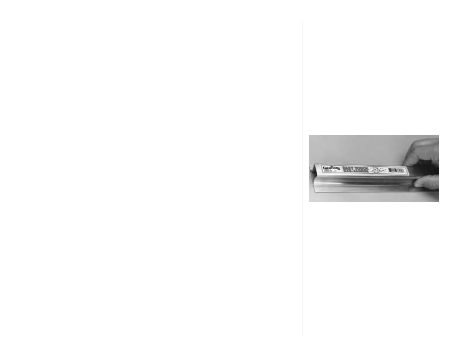
EASY-TOUCH™BAR SANDER
A flat, durable, easy to handle sanding tool is a
necessity for building a well finished model. Great
Planes makes a complete range of Easy-Touch Bar
Sanders (patented) and replaceable Easy-Touch
Adhesive-backed Sandpaper. While building the P-
39 we used two 5-1/2" [140mm] Bar Sanders and
two 11" [280mm] Bar Sanders equipped with 80-grit
and 150-grit Adhesive-backed Sandpaper. Here's
the complete list of Easy-Touch Bar Sanders and
Adhesive Backed Sandpaper.
5-1/2" [140mm] Bar Sander (GPMR6169)
11" [280mm] Bar Sander (GPMR6170)
22" [560mm] Bar Sander (GPMR6172)
33" [840mm] Bar Sander (GPMR6174)
44" [1120mm] Bar Sander (GPMR6176)
11" [280mm] Contour Multi-Sander (GPMR6190)
(continued on page 8)
5
Page 6
6
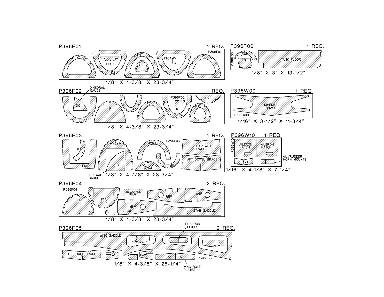
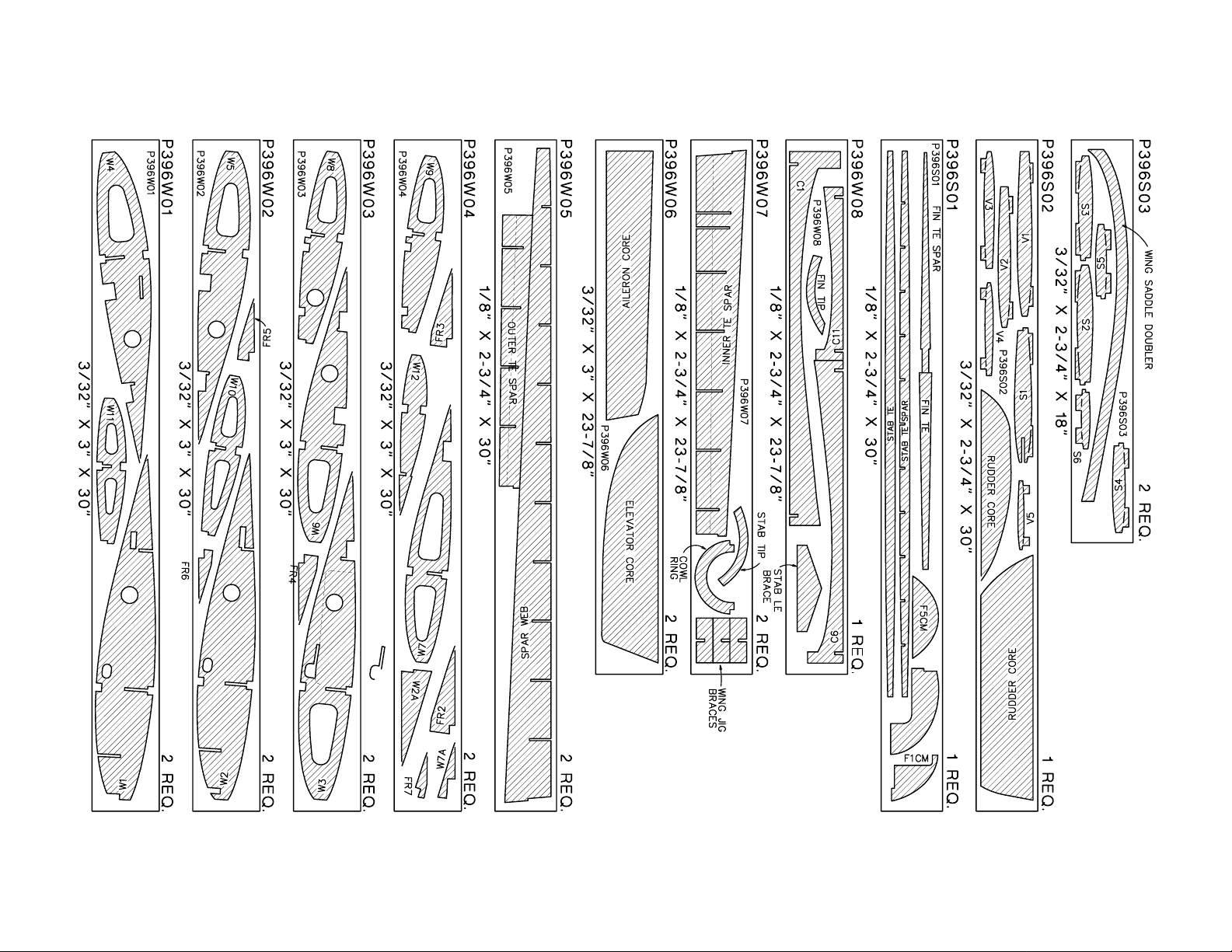
DIE-CUT PATTERNS
Page 7
7
DIE-CUT PATTERNS
Page 8
(continued from page 5)
12' [300mm] roll of Adhesive-backed sandpaper:
80-grit (GPMR6180)
150-grit (GPMR6183)
180-grit (GPMR6184)
220-grit (GPMR6185)
Assortment pack of 5-1/2" [140mm] strips (GPMR6189)
We also use Top Flite 320-grit (TOPR8030, 4 sheets)
and 400-grit (TOPR8032, 4 sheets) wet-or-dry
sandpaper for finish sanding.
IMPORTANT BUILDING NOTES
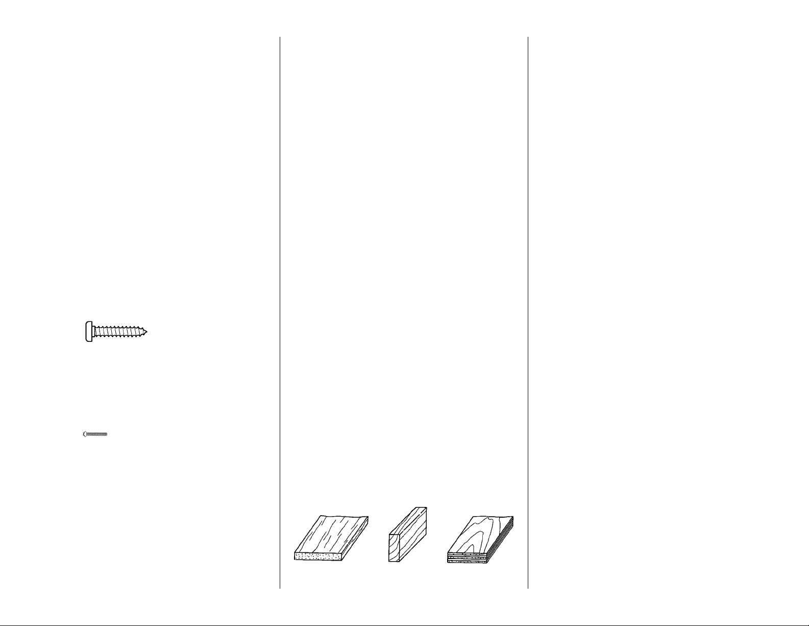
There are two types of screws used in this kit:
Sheet metal screws are designated by a number
and a length.
For example #6 x 3/4" [19.1mm]
Machine screws are designated by a number,
threads per inch and a length.
For example 4-40 x 3/4" [19.1mm]
When you see the term test fit in the instructions, it
means that you should first position the part on the
assembly without using any glue, then slightly
modify or custom fit the part as necessary for the
best fit.
Whenever the term glue is used you should rely
upon your experience to decide what type of glue to
use. When a specific type of adhesive works best for
that step we will tell you what type of glue to use.
Whenever just epoxy is specified you may use either
30-minute epoxy or 6-minute epoxy. When 30-minute
epoxy is specified it is highly recommended that you
use only 30-minute (or 45-minute) epoxy because you
will need the working time and/or the additional strength.
Occasionally we refer to the top or bottom of the
model or up or down. To avoid confusion, the top or
bottom of the model is as it would be when the
airplane is right side up and will be referred to as the
top even if the model is upside down during that
step, i.e. the top main spar is always the top main
spar even if the wing is upside down when you are
working on it. Similarly, move the former up means
move the former toward the top of the fuselage even
if the fuselage is upside down when you are working
on it.
When you get to each step, read that step completely
through to the end before you begin. Frequently
there is important information or a note at the end of
the step that you need to know before you start.
Photos and sketches are placed ahead of the step
they refer to. Frequently you can study photos in
following steps to get another view of the same parts.
COMMON ABBREVIATIONS
Deg = degrees Elev = elevator
Fuse = fuselage " = inches
LE = leading edge Ply = plywood
Stab = stabilizer TE = trailing edge
LG = landing gear mm = millimeters
TYPES OF WOOD
BALSA BASSWOOD PLYWOOD
Metric Conversion Chart
1” = 25.4mm (conversion factor)
Note: An inch/mm scale is provided on the
fuselage plan.
GET READY TO BUILD
1. Unroll the plan sheets. Roll them inside out so
they lie flat.
2. Remove all the parts from the box. Use a ballpoint
pen (not a felt tip pen) to lightly write the name or size
on each piece so you can identify it later. Use the
die-cut patterns on pages 6 and 7, to identify and mark
the die-cut parts before you remove them from their die
sheets. Many of the parts already have numbers
stamped on them, but in some cases the number is
located alongside the parts or only on the die drawings.
You may remove all the die-cut parts from their die
sheets now or wait until you need them. If a part is
difficult to remove, don't force it out but cut around it with
a #11 blade. After you remove the parts from their die
sheets, lightly sand the edges to remove slivers or diecutting irregularities. Save some of the larger leftover
pieces of wood.
3. Separate the parts into groups such as stab, fin,
wing, and fuse. Store smaller parts in zipper-top
food storage bags.
1/64" = .4mm
1/32" = .8mm
1/16" = 1.6mm
3/32" = 2.4mm
1/8" = 3.2mm
5/32" = 4mm
3/16" = 4.8mm
1/4" = 6.4mm
3/8" = 9.5mm
1/2" = 12.7mm
5/8" = 15.9mm
3/4" = 19mm
1" = 25.4mm
2" = 50.8mm
3" = 76.2mm
6" = 152.4mm
12" = 304.8mm
15" = 381mm
18" = 457.2mm
21" = 533.4mm
24" = 609.6mm
30" = 762mm
36" = 914.4mm
8
Page 9
BUILD THE TAIL SURFACES
MAKE THE STAB SKINS
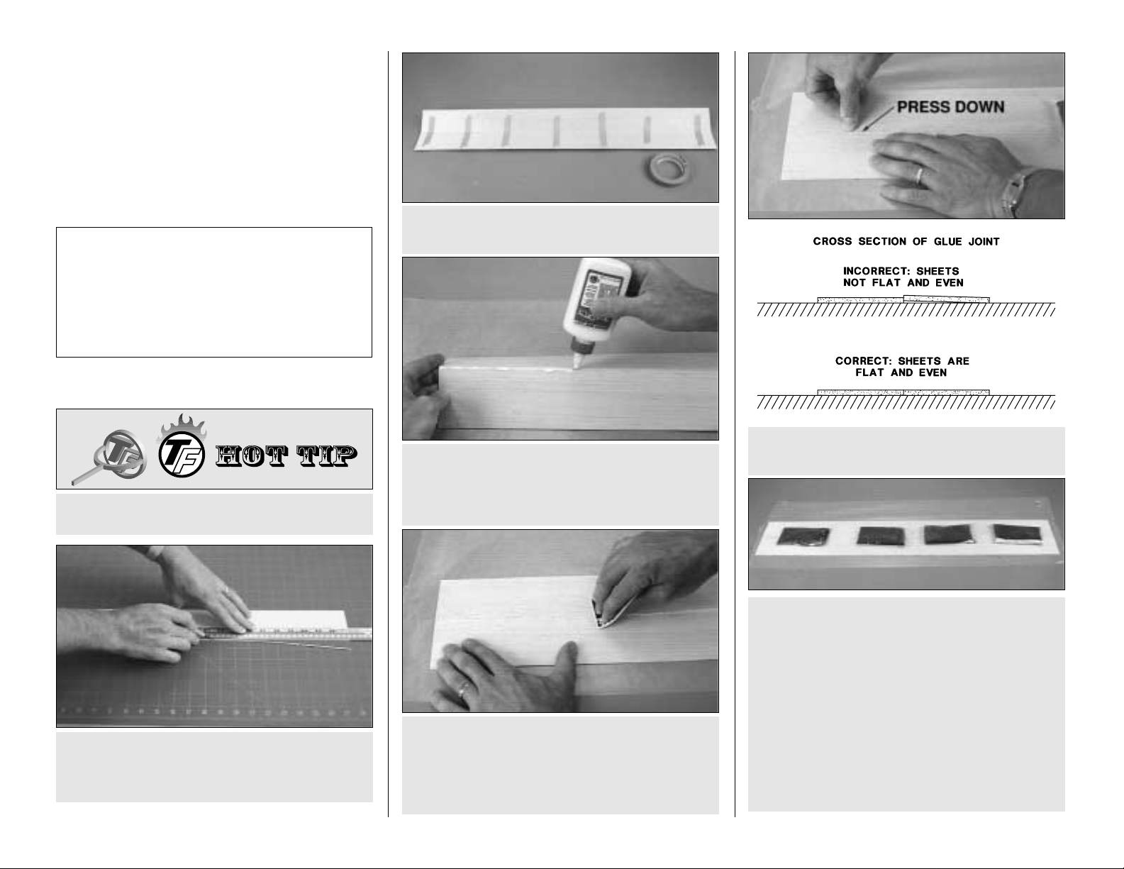
❏ 1. Use the Hot Tip that follows or your own method
to glue two 1/16" x 3" x 30" [1.6 x 76 x 762mm] balsa
sheets together to make a 1/16" x 6" x 30" [1.6 x 152
x 762mm] sheet for one of the stab skins.
F. Place weights on top of the sheets to hold them
down. We prefer plastic bags filled with lead shot, but
anything similar will do the job.
G. After the glue dries, remove the weights and
masking tape. Sand the sheet flat with your bar sander
and 150-grit sandpaper. The idea is to sand the
sheeting before you glue it to the structure. This
eliminates low spots that can occur over the ribs from
excessive sanding.
This is the same procedure we recommend when it is
time to make the wing and fuse skins.
E. Inspect the seam and press the sheets together
where they do not align.
D. Use a credit card or something similar to
simultaneously press the sheets flat as you squeegee
the excess glue from the seam. Wipe the glue off your
squeegee so it’s ready for the next time. Immediately
proceed to the next step.
C. Place a sheet of Plan Protector or wax paper on
your workbench. Turn the taped together sheets over
and apply aliphatic resin (wood workers glue such as
Great Planes Pro) to the seams.
B. Tightly tape the trued edges of the sheets together
with masking tape.
A. Use a straightedge and a sharp #11 blade to true
one edge of both sheets. Do not cut all the way
through the first time but make several passes with
your knife to prevent the wood from splitting.
HOW TO MAKE THE STAB SKINS
Top Flite selects balsa that is intended for
sheeting, though occasionally a few of these
sheets may have a small nick or split near the
ends. If your kit contains a few of these sheets,
arrange them and glue them together so the
defects will not interfere with the final shape of
the skin.
9
Page 10
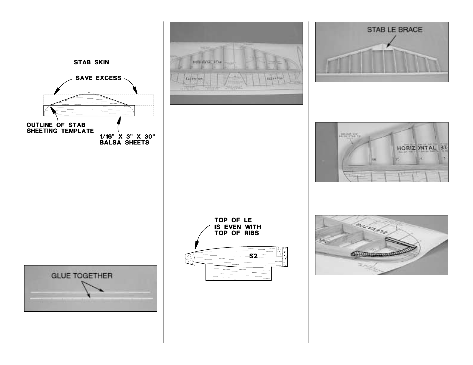
❏ 2. Place one of the balsa skins over the stab plan
and cut the sheeting as shown in the sketch below.
Be sure to cut the balsa skins slightly larger than the
plan to allow for positioning.
❏ 3. Use a small piece of the excess that you cut off
to fill in the small area at the front of the stab skin.
❏ 4. Cut a second skin to the same size and shape.
Build the stabilizer
❏ 1. Cut the stab plan along the dashed line and
tape it to your building board. Cover the stab plan
with Plan Protector.
❏ 2. Glue the die-cut 1/8" [3.2mm] balsa stab TE
spar to the die-cut 1/8" [3.2mm] balsa stab TE.
These pieces are symmetrical so it does not matter
how you join them.
❏ 3. Insert all the die-cut 3/32" [2.4mm] balsa stab
ribs except for rib S1 into the TE spar and place the
assembly over the plan.
❏ 4. Make sure all the ribs are fully seated into the
TE spar and that the jig tabs are contacting the
building board. Use a square to make sure the TE is
perpendicular to your building board. Glue the ribs
to the TE with thin CA.
❏ 5. Sand a bevel on the front of the ribs to
accommodate the aft sweep of the LE. Cut the 5/16”
x 15” [7.9 x 381] tapered balsa leading edge at the
angles shown on the plan. When you are satisfied
with the fit, glue the leading edge to the front of the
ribs. Be sure that the top of the tapered balsa leading
edge is flush with the top of the ribs.
❏ 6. Fit the Stab LE Brace into the slot in rib S1. Test
fit S1 and the stab brace as shown on the plan.
When you are satisfied with the fit, glue S1 and the
stab LE brace into position.
❏ 7. Glue the stab tips to the stab where shown on
the plan. Make sure the tips are centered (vertically)
on tip ribs S6 and the trailing edge.
❏ 8. Relocate any T-pins that are protruding above
the structure so they will not be in the way when you
sand the stab tip and the leading and trailing edges.
Use a bar sander and 80-grit sandpaper to bevel the
top of the stab tips to accommodate the sheeting.
Shape the top of the TE and LE to blend with the
stab tips and the ribs. We've marked the centerline of
the stab tip and highlighted the top of it so you can
see how the stab tip is tapered.
10
Page 11
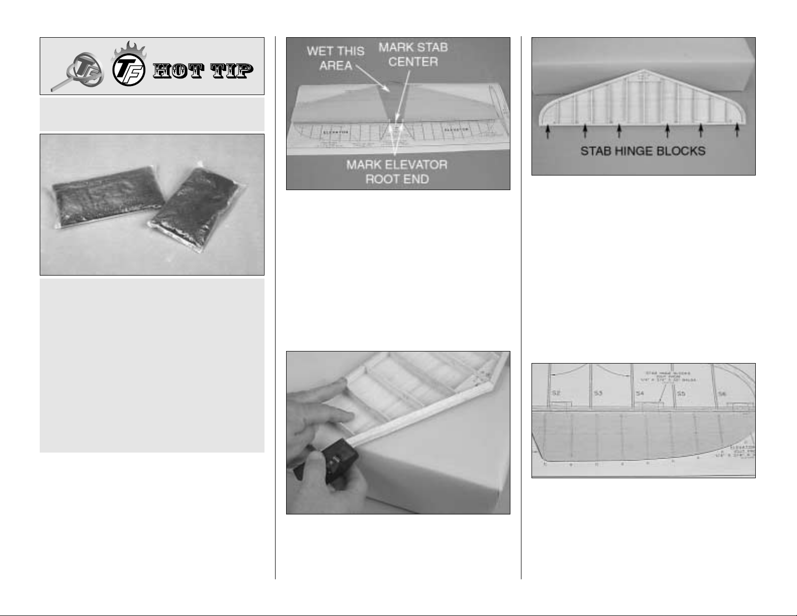
❏ 9. Before you sheet the top of the stab, refer to the
photo at step 10. Use a ballpoint pen and a square
to mark the center of the stab and the root end of
both elevators on the TE of the stab. The marks will
help you align the stab with the fuse and align the
elevators with the stab later on.
❏ 10. Sheet the top of the stab with one of the stab
skins you've already prepared. We recommend
using aliphatic resin to glue the skin to the ribs and
CA to glue the skin to the TE, LE and tips. Wet the
outside of the sheeting in the middle near the leading
edge. This will make the skin flexible enough to glue
to the structure. Apply aliphatic resin to the ribs and
position the top skin on the stab. Place your weights
on top of the stab skin, then use CA to glue the skin
to the LE, TE and tips. Leave the weights in position
until the aliphatic resin dries. Thirty minutes to an
hour is enough time.
❏ 11. Remove the stab from your building board. T urn
the stab over and cut the jig tabs from the bottom of
the ribs, then trim the bottom of the LE even with the
ribs. Trim the stab tips and the bottom of the TE near
the tips the same way you did on the top.
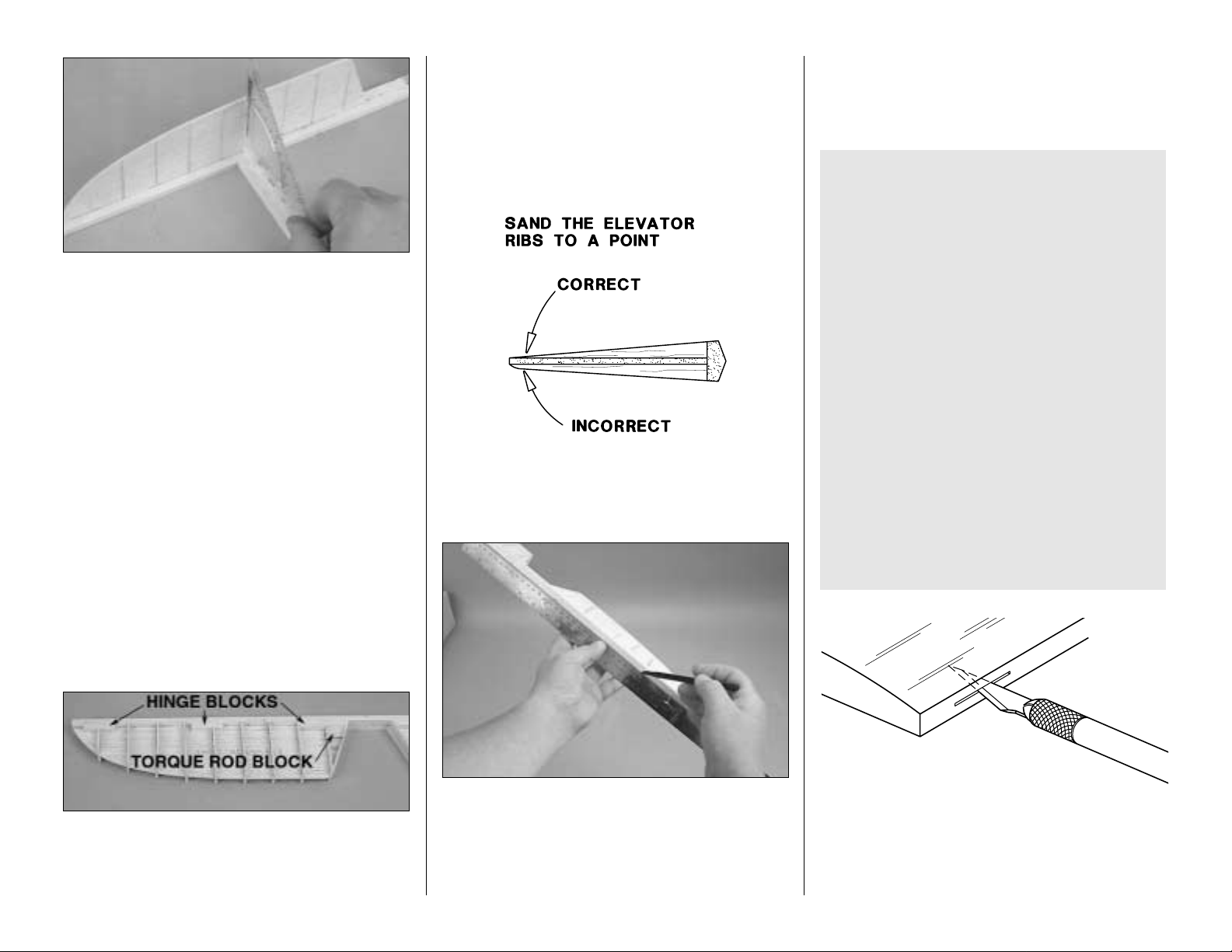
❏ 12. Cut the stab hinge blocks from one of the
1/4" x 3/4" x 30" [6.4 x 19.1 x 762mm] balsa sticks.
Glue the hinge blocks to the TE, ribs, and top
sheeting where shown on the plan. Trim the hinge
blocks even with the TE and ribs.
❏ 13. Sheet the bottom of the stab with the other
stab skin you prepared. Use care not to add any twist
to the stab as it is no longer supported by the jig tabs.
Once again, we suggest using aliphatic resin to glue
the skin to the ribs and medium CA for the rest.
Build the elevators
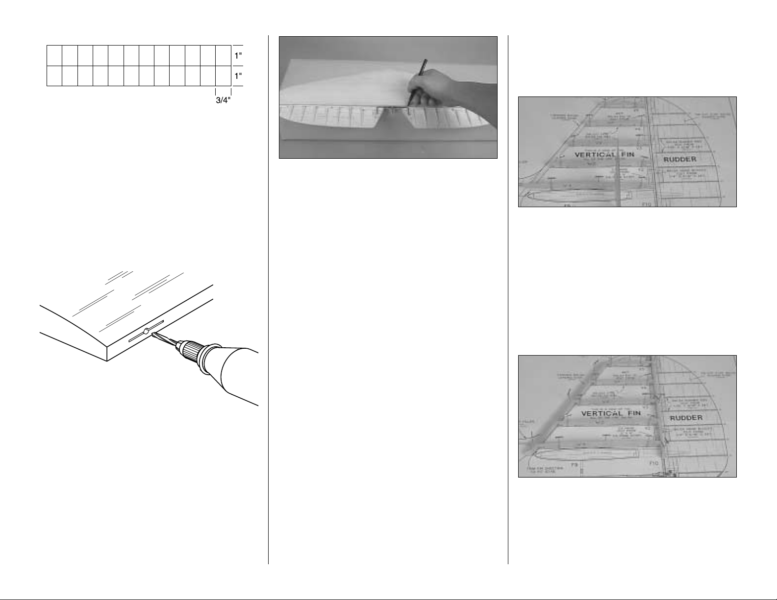
❏❏1. Mark the location of the elevator ribs on both
sides of one of the die-cut 3/32" [2.4mm] balsa
elevator core where shown on the plan. This is easy.
Simply lay the die-cut core on the plan and draw a line
from the "tick" marks at the leading and trailing edge
of the elevator core. This will give you the positioning
for the ribs. When you have completed one side
transfer the lines to the other side.
When we glue sheeting to a structure (wing, stab,
fin), we use plastic bags filled with lead shot to
hold the sheeting down. These plastic bags filled
with lead take the shape of the curved surfaces to
apply uniform pressure and do not put marks in
the balsa wood. You can purchase lead shot at
most stores where hunting supplies are sold. We
use #6 lead shot. One 25 lb. [1.134kg] bag costs
approximately fifteen to twenty dollars. You may
use small zip lock food storage bags to hold the
shot. Tape the bags shut to make sure they don't
open. Each bag should hold between 2-3 lbs.
[907-1361g.] of lead. Ten to fifteen 2-3 lbs. [9071361g.] bags should be enough for most projects.
WEIGHT BAGS
11
Page 12
❏❏2. Cut a 1/4" x 3/4" x 30" [6.4 x 19.1 x 762mm]
balsa stick to the length shown on the plan for the
elevator leading edge. Use a straightedge to draw
a center line the length of the elevator leading edge.
Glue the elevator core to the LE directly on top of the
line so that the core will be centered on the LE. Use
a square to make sure you glue the LE perpendicular
to the elevator core.
Hint: Place a 1/4" [6.4mm] piece of balsa under the
square to raise it to the level of the LE.
❏ ❏ 3. Make the elevator hinge blocks from a 1/4"
x 5/16" x 24" [6.4 x 7.9 x 610mm] balsa stick. Glue
the hinge blocks to the elevator as shown on the plan
(Do this for the top and bottom of the elevator core).
See photo at step 5.
❏❏4. Make the elevator torque rod blocks from
1/4" x 5/16" x 24" [6.4 x 7.9 x 610mm] balsa. Glue the
blocks to the elevator as shown on the plan. (Do this
for the top and bottom of the elevator core.) See
photo at step 5.
❏❏5. Use four 1/16" x 5/16" x 24" [6.4 x 7.9 x
610mm] balsa sticks to make the elevator ribs. Cut
the sticks to the correct length, then glue them to the
elevator core and the leading edge of the elevator.
❏❏6. Use a piece of leftover 1/16" [1.6mm]
sheeting to make the elevator root cap. Glue the
root cap into position.
❏❏7. Place the elevator on the stab TE and shape
the elevator LE to match the shape of the stab TE.
❏❏8. Proceed slowly and carefully, shaping the
elevator ribs and the hinge blocks to match the
elevator LE and the cross section on the plan.
❏❏9. Insert two T-pins through the center of one of
the elevator LE, near the tip and near the root. Place
a straightedge across the T-pins and draw the
centerline on the elevator LE with a ballpoint pen.
Draw a centerline along the TE of the stab the
same way.
❏ 10. Carefully cut away the center section of the
elevator leading edge so the elevators match the
shape as shown on the plan. Note which elevator
matches which side of the stab.
❏❏11. Mark the location of the hinge slots on the
elevator and stab where shown on the plan. With a
#11 blade, cut the hinge slots in the elevator and the
stab along the centerlines you marked earlier.
IMPORTANT NOTES ABOUT CA HINGES
This kit is supplied with a CA hinge material
consisting of a 3-layer lamination of Mylar and
polyester. It is specially made for hinging model
airplane control surfaces. When properly
installed, this type of CA hinge provides the best
combination of strength, durability and easy
installation. We trust all of our Gold Edition war
birds to these hinges, but it is essential to install
them correctly. Carefully follow the hinging
instructions in this manual for the best result.
The most common mistake made by modelers
when installing CA hinges is making the hinge
slots too tight restricting the flow of CA to the back
of the hinges; or not using enough glue to fully
secure the hinge over its entire surface area. This
results in hinges that are only tack glued into the
hinge slots. The techniques for cutting the hinge
slots and gluing in CA hinges (near the end of the
manual) have been developed to ensure thorough
and secure gluing.
12
CUT HINGE SLOT
WITH HOBBY KNIFE
AND #11 BLADE
Page 13
❏ 12. Using the sketch above, cut six hinges from
the CA hinge strip supplied with this kit. Snip the
corners off so they go into the slots easier. You may
cut all the hinges now, or cut them as you need them.
❏❏13. Test fit the hinges into the slots. If the hinges
do not slide into the slots easily, work your knife
blade back and forth in the slot a few times to provide
more clearance (it is really the back edge of the
blade that does the work here in widening the slot).
❏❏14. Drill a 3/32" [2.4mm] hole, 1/2" [12.7mm]
deep in the center of the hinge slots. Use a rotary
tool with a 3/32" [2.4mm] drill bit or a carbide cutter
for the best results. Reinsert your knife blade to
clean out the slot after you drill the holes.
❏❏15. Test fit the elevator to the stab with the
hinges. If any hinge slots are not wide enough or are
misaligned, make adjustments so the elevators
accurately fit the stab.
Return to Step 1 and build the other elevator.
❏ 16. Determine which side of the stab looks the
best. Designate that side as the top. Use a file or a
rotary tool with a cut-off wheel to remove sharp
edges or burrs on the ends of the elevator joiner
wire. Place the horizontal Stab and elevators over
the plan and position the elevator joiner wire on the
top of the elevators in the location shown. Mark the
leading edge of the elevators where the arm portion
of the joiner wire will enter as shown on the plan.
❏ 17. Drill a 9/64" (or 1/8") [3.6mm] hole at the marks
you made on the centerline of both elevator leading
edges for the joiner wire. Cut a groove in the
leading edge of both elevators to accommodate the
joiner wire.
Hint: Use a 5/32" [4mm] brass tube sharpened at
one end to cut the grooves.
❏ 18. Bevel the leading edges of the elevators to a
"V" as shown in the cross section on the plan. Use
the centerline on the elevator leading edges as a
guide. Test fit the elevators to the stab with the joiner
wire and the hinges. Note that the horn on the joiner
wire points downward. Cut a small notch in the TE of
the stab for the horn on the joiner wire. If necessary,
remove the joiner and tweak it so both elevators are
in the same plane.
❏ 19. Once more, test fit the elevators to the stab
with the hinges and the joiner wire. Make sure you
can obtain the control throws indicated on page 43 of
the manual. If you cannot, increase the "V" on the
leading edge of the elevators.
Set the stab and elevators aside.
Build the fin and rudder
❏ 1. Tape the fuse plan to your building board. Cover
the fin and rudder portion of the plan with Plan Protector.
❏ 2. Pin balsa fin ribs V1 through V5 to the plan
using T-pins as shown in the photograph. Check that
the fin ribs are perpendicular to the building board
using a triangle or square.
❏ 3. Carefully bevel the front of the ribs to
accommodate the sweep of the tapered LE stick.
❏ 4. Cut the balsa leading edge from a 5/16" x 15"
[7.9 x 381mm] tapered balsa leading edge. Cut it to
the length shown on the plan.
❏ 5. Pin the balsa leading edge stick and the die-cut
1/8” balsa fin TE spar to the plan in the same manner
as the ribs in step 2. Be sure to align the top of the fin
LE with the tops of the ribs, allowing the excess to
protrude below the ribs (to be trimmed later). Do the
same with the fin TE spar. Once you are satisfied with
the fit, glue the ribs to the LE and TE.
13
DRILL A 3/32" HOLE
1/2" DEEP, IN CENTER
OF HINGE SLOT
Page 14
❏ 6. Glue the die-cut 1/8” balsa fin TE to the fin
TE spar.
❏ 7. Glue the die-cut 1/8 balsa fin tip between the TE
spar and the top of V5. Be sure that the tip is centered
on the LE and TE as shown in the photograph.
❏ 8. Cut three balsa hinge blocks from the 1/4" x
5/16" x 24" [6.4 x 7.9 x 610mm] balsa stick and glue
in place as shown on the plan.
❏ 9. Rearrange any T-pins that protrude above the
structure so they will not interfere with your bar
sander. Lightly sand the top of the LE and TE to
match the airfoil shape of the ribs to accommodate
the fin skin.
❏❏10. Cut a 1/16" x 3" x 30" [1.6mm x 76 x 762mm]
balsa sheet into two 8-1/2" [215.5mm] long pieces
and one 4-1/2” [114mm] long piece. Edge glue the
three sheets together in the same way the stab
sheeting was done. This will become one of the fin
skins. Use the Fin Skin Pattern on the plan to make
one fin skin.
❏ 11. Repeat step 10 to make a second fin skin.
❏ 12. Remove the T-pins from the fin assembly and
glue one of the fin skins in position. Align the rear of
the skin with the TE of the fin and the bottom of the
skin with V1.
❏ 13. Remove the fin from the building board.
Remove the jig tabs from the other side of the fin and
lightly sand the fin ribs, LE and TE to shape.
❏ 14. Glue the second fin skin in position on the fin.
Take care not to twist the fin when gluing the fin skin
in place.
❏ 15. At this point set the fin aside and proceed with
the assembly of the rudder.
❏16. Glue the die-cut 3/32" [2.4mm] balsa front and rear
rudder core pieces together to form the rudder core.
❏ 17. Mark the location of the rudder ribs on both
sides of the die-cut 3/32" [2.4mm] balsa rudder core
where shown on the plan. Use the same procedure
as in step 1 of building the elevator.
❏ 18. Cut a 1/4" x 1/2" x 24" [6.4 x 12.7 x 610mm]
balsa stick to the length shown on the plan to make
the rudder leading edge.
❏ 19. Draw a centerline on the LE material and glue
the rudder core on to the center line.
❏❏20. Cut four balsa hinge blocks from a 1/4" x
5/16" x 24" [6.4 x 7.9 x 610mm] balsa stick and fit
them to the LE of the rudder as shown on the plan.
Glue them in place on the left side of the rudder as
shown in the photo at Step 22.
❏❏21. Use a 1/16" x 5/16" x 24" [1.6 x 7.9 x
610mm] balsa stick to make the rudder ribs. Cut the
sticks to the correct length, then glue them to the
rudder cores and the leading edge of the rudder.
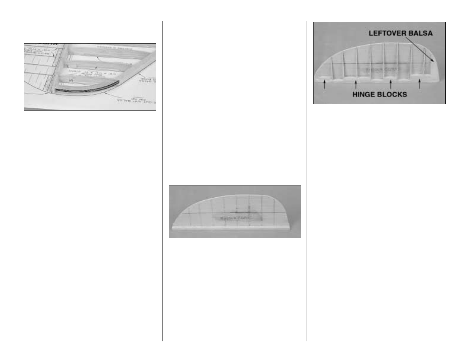
❏❏22. Glue a leftover piece of balsa to the bottom
of the rudder to help in shaping the rudder for
covering. The photo above shows one side of the
rudder with the ribs, hinge blocks and leftover balsa
in place and shaped.
Repeat steps 20-22 for the right side of the rudder.
❏ 23. Draw a centerline on the LE of the rudder.
Mark the location of the hinges. Cut your hinge slots
in the same manner you did for the elevator. When
this is complete, taper the LE the same way as the
leading edge of the elevator.
❏ 24. Install the rudder control horn. Rest the small
nylon control horn on the rudder as indicated on the
plan and mark where to position the die-cut 1/16"
[1.6mm] plywood control horn mount. Remove the
balsa from this area and glue the control horn mount to
the rudder. Mount the control horn to the plywood base
with two #2 x 3/8” sheet metal screws.
❏ 25. It's time to do the final sanding of the rudder.
Verify the shape and taper of the rudder against the
fin. When you are satisfied, set it aside and we'll get
started on the fuselage.
14
Page 15
BUILD THE FUSELAGE
Frame the Fuselage top
❏ 1. Cut the fuselage plan on the dashed lines and
tape the fuse top view to your building board. Cover
the plan with Plan Protector.
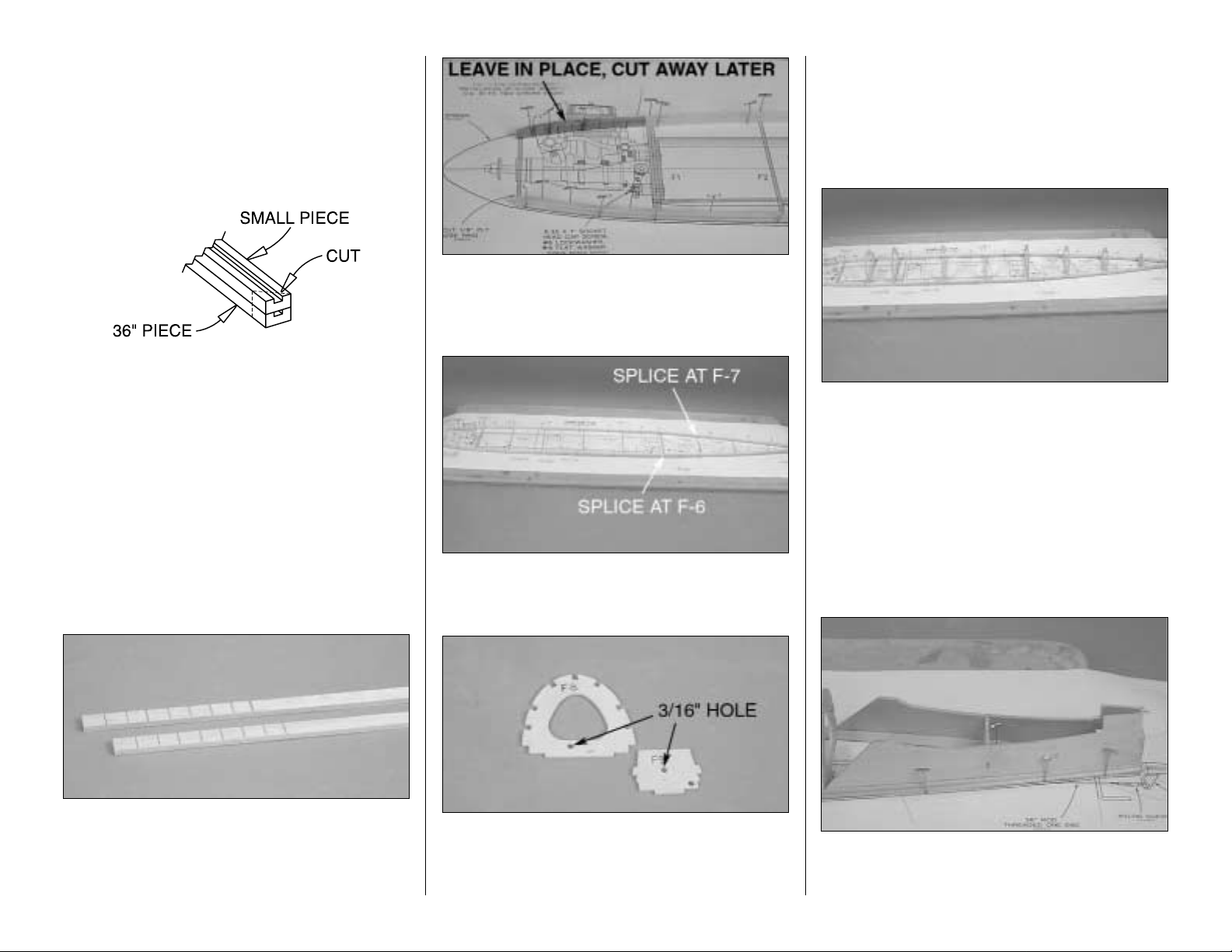
❏ 2. Gather the three 3/16" x 3/8" x 36" [4.8 x 9.5 x
914mm] grooved main stringers. Cut one of the
stringers into two pieces. One piece will be 20-3/4"
[527mm] long; the other piece, 15-1/4" [387.5] long.
Place the 20-3/4 " [527mm] long main stringer on top
of the 36" [914mm] main stringer so the ends align.
Cut the stringers and position them so that the left
side main stringer has the splice at former F6. Do the
same thing with the 15-1/4" [394mm] main stringer
on the right side but with the splice location at F7.
The splice locations are noted on the top view of the
plan. Cut, splice and glue them together at an
approximately 45-degree angle as shown in the
sketch (use your miter box if you have one).
❏ 3. Use a razor saw to cut small v-notches, 3/32"
[2.4mm] deep in the inside of the 36" [914mm]
stringer. Do this in the area that will be glued between
the nose ring and F1. This will allow the stringers to
conform to the shape as shown on the plan.
❏ 4. You will notice that the right side main stringer
gets cut away forward of F1. Leave it in place for
now. This will help to secure the nose ring as we
begin the process of framing the fuselage.
❏ 5. Pin the two stringers to the plan so the left side
main stringer is spliced at F6 and the right side main
stringer is at F7 as shown on the plan.
❏ 6. Refer to the Pushrod Locations area on the fuse
plan and drill 3/16" [4.8mm] holes through the punch
marks in the die-cut 1/8" [3.2mm] plywood formers
F8 and F9. One hole in F8, two in F9.
❏ 7. Locate the two formers F1 and F1A. Using
6-minute epoxy, glue the two F1 formers together
and then the two F1A formers and set them aside
to dry . Do not glue the F1 and F1A formers together
at this time.
❏ 8. Test fit all die-cut 1/8" [302mm] plywood formers
(F2 through F10) to the main stringers over their
locations on the plan. You may need to bevel the
notches in some of the rear formers to accommodate
the angle at which they join the main stringers. Use a
small square to make sure the formers are vertical
and glue them to the main stringers. Don't be
concerned if the formers are slightly warped. You will
be able to straighten them when you add the stringers.
❏ 9. Test fit and then glue the Stab Saddles into
position over the main stringers and to former F9
and F10.
15
Page 16

❏ 10. Test fit former F1 onto the main stringers. Use
the die-cut 1/8" [3.2mm] ply firewall gauge (FG) to
set the proper amount of down thrust. Permanently
glue F1 into position.
❏ 11. Carefully bevel the front of the main stringers
to the angle shown on the plan. Glue one half of the
nose ring, part NR, to the face of the main stringers.
Be certain when gluing the nose ring into position
that the notches for the stringers are on the left side
of the fuselage.
❏❏12. Temporarily place the stab on the stab saddles
and hold it in place with weights. Cut the ends of two
3/16" x 3/16" x 30" [4.8 x 4.8 x 762mm] balsa stringers
so they fit the stab saddle as shown in the photo (from
now on, all 3/16" x 3/16" x 30" [4.8 x 4.8 x 762mm]
stringers will be referred to as just stringers). Cut the
other end of the stringers so they end in the middle of
former F3. Use a small square to hold the formers
vertical as you glue the stringers to them and to the
stab saddle.
❏ 13. Repeat step 12 for the right side of the fuselage.
❏ 14. Glue stringers from F3 to the front of the nose
ring on the left side of the fuselage. Glue stringers
from F3 to F1 on the right side. Use the firewall gauge
to set the down thrust angle on the nose ring to match
the firewall.
❏ 15. Glue one of the 1/8" x 3/16" x 36" [3.2 x 4.8 x
914mm] stringers into the slot in the side of the main
stringer. Cut part of another stringer to length to fill
the rest of the slot. Repeat this for the other side of
the fuselage.
❏❏16. Test fit one of the 3/32" x 3" x 36" [2.4 x 76
x 914mm] balsa sheets onto the main stringer on the
left side of the fuselage. Fit the sheet from the back
of the fuselage forward. Minor trimming may be
required to get a good fit. When you are satisfied
with the fit, tape the sheet in place where the
sheeting meets the main stringer.
❏❏17. Trim the sheeting so that it can be glued to
the second stringer. When you are satisfied with the
fit, cut the excess sheeting at F4. Glue the sheeting
to the two side stringers, the main stringer, the stab
saddle and F4.
Hint: Form the sheeting to the stringer and draw a
line along the stringer from the back side of the
sheet. Now mark a line 3/32" [2.4mm] below that
line. This will give you a cut line that will allow the
sheeting to be in the center of the stringer.
❏ 18. Repeat step 16 & 17 for the right side of
the fuselage.
❏ 19. Cut one of the 3/32" x 2 3/4" x 30" [2.4 x 70 x
762mm] balsa sheets to a length of 14" [356mm].
Test fit the 14" [356mm] long balsa sheet onto the
main stringer from F4 forward to former F1 on the
fuselage right side. Trim the sheeting to fit between
the main stringer and the second stringer. When
satisfied with the fit, glue the sheeting to the stringers
and the formers F1- F4.
❏ 20. Measure the distance from former F4 to F2.
Cut the remaining piece of sheeting to that length
and glue it in position on the left side of the fuselage.
Note: The photo in step 19 shows the proper
positioning for the sheeting when you have
completed steps 19 and 20. Subsequent
photographs show the sheeting already in place to
the nose ring. Disregard the fact that the sheeting is
there, the instructions will be correct.
16
Page 17

Mount the stab and fin
❏ 1. Remove the elevators from the stab.
❏ 2. Place the stab on the stab saddle, aligning the
centerline mark on the trailing edge of the stab with
the center of the fuselage. Place weights on top of
the stab to hold it in position. View the fuse from the
rear and make sure the stab is level. To confirm,
place balsa blocks (not included) under both sides of
the stab and measure the distance from the
centerline on the TE of the stab to your building
board. If necessary, reposition the balsa blocks, shift
the weight or carefully sand the high stab saddle until
the stab will rest level. Be sure to sand carefully and
a little at a time so as not to change the incidence
angle of the stab.
❏ 3. With the stab resting on the saddles and
weights on top to hold it down, check the stab
incidence by placing an Incidence Meter across one
side of the stab, then the other side of the stab near
the fuse. If necessary, adjust the stab saddles so the
incidence is parallel with your building board.
❏ 4. Place a leftover piece of 3/16" x 3/16" [4.8 x
4.8mm] stringer in the top center notch of formers F3
and F4. Insert a T-pin in the center of the stringer at F3.
Place a Hobbico Retractable Fabric Tape Measure
(HCAR0478) (or any suitable measuring device) over
the T-pin and measure the distance from the pin to the
left tip of the horizontal stab and then to the right tip of
the stab. Adjust the stab until the distance from the pin
is the same on both sides of the stab
❏ 5. Recheck to see that your stab is still level. Mark
the exact location where you will glue the stab to
the saddle.
❏ 6. Now that you are sure the stab will align, remove it
and apply 30-minute epoxy to the joining areas and
glue it to the fuse sheeting and the ply stab saddle. Use
the tape measure technique to recheck your alignment.
Make sure the stab is level and the incidence is correct.
Wipe away excess epoxy before it cures. Do not disturb
the fuse until the epoxy is fully cured.
❏ 7. Test fit the fin on the fuselage at former F10.
Sand a little of the stab where the leading edge comes
together. This is necessary to give proper clearance
for the leading edge of the fin to attach to the front of
the stab. Sand the fin sheeting as needed to achieve
a good fit with the stab.
❏ 8. Remove the vertical fin and place the elevator
joiner wire into position into the slot in the stab saddle.
❏ 9. After you are satisfied with the fit of the fin to the
stab, apply a film of 30-minute epoxy to the base of
fin rib V1 and to the stab sheeting. Pin V1 of the fin
assembly so that you get a good glue joint between
V1 and the stab. Align the LE of the fin with the
centerline on the plan. Immediately proceed to the
next step.
17
Page 18

❏ 10. Hold the fin vertical with masking tape strapped
across the top of the fin over to both stab tips. Adjust
the tension on the masking tape to pull the fin to one
side or the other until it is vertical. Re-check alignment
and do not disturb the fin until the epoxy is fully cured.
❏ 11. Draw a centerline on the balsa TE. Place the
rudder into position on the rudder TE and mark the
location of the hinges. Cut the hinge slots into the fin
and the rudder LE.
❏12. Now's a good time to sand all of the components
of the tail structure.
Let's get the top of the fuselage sheeted and get it off
the building board!
Sheet the top of the fuselage
Before proceeding with sheeting the top of the
fuselage, you need to decide how you are going to
finish the cockpit area. You have the option of
creating a full cockpit or simply gluing a pilot bust
under the canopy. There is no question the addition
of the full cockpit interior is going to really add to your
model. We would suggest that you take the
additional time to do this.
❏1. Cut formers F3, F4 and F5 flush with the top of the
sheeted stringers. This will create our cockpit area.
❏ 2. Locate and glue the die-cut 1/8" [3.2mm] ply
former F5C and former IP into position as shown on
the plan.
❏ 3. Test fit the stringers into position in the notches
on former F5C back to the tail. At the tail, sand the
stringers to fit where they meet with the fin and stab.
When you're satisfied with the fit, glue the stringers
in place.
❏ 4. Test fit the stringers into position in the notches
on former IP forward to the nose ring and firewall.
The stringers go to the nose ring on the left and
center stringer. The right side stringer should stop at
the front of F1. Glue them in place when you are
satisfied with the fit.
Have you decided on your cockpit option yet? No
more procrastination!
18
Page 19

❏ 5. Cut away former F3 and IP as shown in
the photograph.
❏ 6. Cut the tail fillet pattern from the plan and
make two of them from some of the leftover pieces of
3/32 [2.4mm] balsa sheeting.
❏ 7. The fillet pattern is slightly oversized, so you will
have to do some final fitting to get a good fit. The fillet
should fit around the tail surfaces and forward to the
center of F8. When you are satisfied with the fit, wet
the fillet pieces with a solution of water and alcohol.
This will allow the balsa to become flexible without
cracking. When the balsa has become flexible
enough, glue the fillet into position.
❏8. After the fillet has been glued into place use some
Lightweight Hobby Filler (Balsa Color, HCAR3401)
to fill any gaps and create a smooth fillet.
❏ 9. Cut one of the sheets of 3/32" x 2-3/4" x 30" [2.4
x 70 x 762mm] balsa sheeting to form the front and
rear decking. Before test fitting it into place, wet the
wood with the water and alcohol solution so that the
wood becomes flexible enough to conform to the
shape of the formers. We recommend cutting a piece
for the left side of the fuselage and one for the right,
joining the two sheets on the center stringer. The
radius of the formers is too tight to complete the
sheeting with one sheet of balsa. When you have
completed one side of the fuselage do the same for
the other side.
NOTE: The photo above, incorrectly shows sheeting
on the left side of the fuselage in the nose area. Do
not sheet the area from F-2 forward to the nose ring
on the left side of the fuselage.
If you are choosing to have a full cockpit interior,
make a deck out of the 1/16" x 3" x 24" [1.6 x 76
x 610mm] balsa sheeting. This should be placed
between formers F4 and F5C and trimmed flush
with the side stringers.
CONSTRUCTION WITH A FULL
COCKPIT INTERIOR
If you are choosing not to have a full cockpit
interior, make a deck out of the 1/16" x 3" x 24"
[1.6 x 76 x 610mm] balsa sheeting. This should
be placed between formers IP and F5C and
trimmed flush with the side stringers.
CONSTRUCTION WITHOUT A FULL
COCKPIT INTERIOR
19
Page 20

❏ 10. Cut out the ABS plastic exhaust stacks. After
trimming, mark "left"on one and "right" on the other,
on the back of each piece so you are sure to get a
good fit when doing the final assembly. Tape one in
place on the side of the fuselage as shown on the
plan. Trace around the part with a pen to indicate
where you will be cutting balsa wood away.
❏ 11. Cut out the area you just marked. Do this
carefully so the exhaust stack will have a good fit into
this cavity. Set the stack aside for now. It will be
glued in place after the final covering.
❏ 12. Do the same for the other side of the fuselage.
That's it for the top half of the fuselage. You're
halfway there! Let's proceed with the bottom half.
Build The Bottom Of The Fuselage
❏ 1. Place the fuselage upside down in a stand. We
prefer the Robart Super Stand. You can see it in
many of the following photos.
❏ 2. Locate the die-cut 1/8" [3.2mm] plywood
fuselage formers F1A through F10A for the bottom
of the fuselage.
❏ 3. Glue former F3AD to F3A. From now on the
F3A/F3AD assembly will be referred to as F3A.
❏ 4. Locate the two wing saddles. Cut 1/8" [3.2mm]
off of the front end of one of the saddles. This will be
the right wing saddle. This is very important! By
assembling the saddle correctly you will have the
proper amount of right thrust needed for the plane to
fly well.
❏ 5. If you will be installing fixed landing gear, drill
3/16" [4.8mm] holes in formers F2A through F5A for
the nose gear steering pushrod. These holes are on
the left side of the former. Refer to the plan for the
location of the holes. Cut the slot on the left wing
saddle as shown in the sketch above. There are
embossed cut lines on the saddle.
PPPP--33339999 FFFFaaaacccctt
tt
At the time this manual was published there
was only one flyable P-39 in the world!
20
Page 21

❏ 6. Test fit formers F1A, F3A and F6A to the wing
saddle. The formers and saddle have been notched
to allow the structure to interlock together. When you
assemble this structure, the longer wing saddle
should be on the left side of the assembly.
Remember, you are building this upside down. Make
sure that you have the longer wing saddle on what
will be the left side of the fuselage.
❏ 7. Both formers must be square to the saddles.
When you are satisfied with the fit, glue F3A and F6A
to the saddles with CA.
❏ 8. Glue F1A to the saddle using 30-minute epoxy.
Set the saddle assembly aside to dry.
❏ 9. When the epoxy in the saddle assembly has
cured, test fit the saddle assembly to the fuselage.
❏ 10. When you are satisfied with the fit, glue it
permanently in place onto the fuselage. This should
be done with 5-minute epoxy and some weights to
hold it in place. Allow the epoxy to cure.
❏ 11. Locate the 1/8" x 2-3/4" x 2-3/4"[3.2 x 70 x
70mm] firewall backplate. Glue it to the back of F1
and F1A with 5-minute epoxy. Locate it as shown on
the plan.
❏ 12. Glue two F4A formers and two F5A formers to
each side of the wing saddle as shown on the plan.
Glue former F2A in place as shown on the plan.
❏ 13. Glue formers F7A, F8A, F9A and F10A into
position as shown on the plan. Be sure that they are
straight when you glue them in place. Do not glue
F6AD in position yet.
❏ 14. Temporarily place two balsa side stringers in
position as shown in the photograph. This will give
you the position for gluing F6AD in place. When
satisfied with the fit, glue F6AD to F6A, and remove
the stringers.
Install the Pushrods
❏ 15. Before we close the rest of the fuselage, this
would be a good time to position the pushrods and
servo mounting rails. Locate a 1/4" x 3/8" x 36"
[6.4 x 9.5 x 914mm] basswood stick and cut four
pieces as shown on the plan to fit the fuselage.
These become the servo mounting rails.
❏ 16. Glue the servo mounting rails into position as
shown on the plan (See photo at Step 21.)
❏ 17. Cut a plastic pushrod outer tube to length for
the elevator and put it in place. This tube should go
through the hole that you previously drilled in F9.
Roughen the tube with sandpaper in the areas where
the tubes will be glued.
❏ 18.Mark the rudder pushrod exit on the left side of
the fuse where shown on the fuselage plan. Drill a
3/16" [4.8mm] hole on the mark. Angle the drill
approximately 25 degrees when drilling on the mark.
This will allow the pushrod to exit the fuse at the
correct angle
❏ 19. Cut the plastic pushrod outer tube to length for
the rudder. Roughen the tube with 150 grit
sandpaper where it will be glued to the wood. Glue
the tube in position through the hole you just drilled
in the side of the fuselage.
❏ 20. Cut the .074 wire pushrods to length for each
of the control surfaces. Clean residual oil from the
pushrod wire with a cloth dampened with alcohol or
other solvent. Cut six 3/8” spacers from the white
inner pushrod tube, then slide them, evenly spaced,
onto the wire. Make sure you position the bushings
at the ends of the wire so they will not protrude from
the guide tube, or the controls could become
jammed during flight. If the spacers slide easily onto
the wire, secure them with a drop of thin CA (make
sure the CA sets before you slide the pushrod into
the guide tube!). If the spacers are difficult to slide
on, cut them to a shorter length so they will be a little
easier to slide onto the wire.
21
Page 22

❏ 21. Locate five die-cut 1/8" [3.2mm] ply guide
tube holders. Drill a 3/16" [4.8mm] hole through the
punch mark on the holders.
❏ 22. Support the plastic outer pushrod tube with
the five die-cut 1/8" [3.2mm] ply guide tube holders
by gluing them in place at F6 - F8.
This next step only applies if you are going to
have a fixed gear. Skip step 23 if you are
installing retracts.
❏ 23. Install the plastic pushrod outer tube for the
nose wheel steering by cutting the tube to length and
then inserting it through the holes that you drilled in
the die-cut fuselage formers F2A through F5A on the
left side of the fuselage. The tube should pass
through the slot in the wing saddle and reach to the
front of the firewall. Use a 3/16" [4.8mm] drill to make
a hole in the firewall at the position the pushrod will
exit the firewall.
❏ 24. Mount the elevator, rudder and throttle servos
into position as shown on the plan. Once they are in
place and you are satisfied with the position of the
servos and the plastic outer pushrod tubes, glue the
tubes in place with a few drops of CA.
❏ 25. This is a good time to get the fuel tank
installation finished. Cut the cross-brace on F2 out of
the fuselage. This is necessary to give clearance for
the fuel tank.
❏ 26. It's time for you to make another decision. The
P-39 (as in other models you may have built) has a
very tight compartment for the fuel tank. The easy
way would be to make the fuel tank a permanent
installation. Though it is easier, this has some
potential long-term problems. If you wish to mount it
permanently, go ahead and do that now.
We recommend that you take a little time and use the
following instructions to mount the tank so it can be
removable. It will be a little tedious and may require
you to do a little shaping, but the end result will be
fairly easy tank removal if needed.
❏ 27. Locate the die-cut 1/8" fuel tank floor. Put a
piece of 1/4" [6.4mm] foam between the floor and the
fuel tank. Attach the tank to the floor with #32 rubber
bands (included in the kit). Trial fit the fuel tank into the
fuselage. The floor should extend all the way to the
firewall and 1/4" [6.4mm] beyond former F3. The
notches in the leading edge of the floor are there to
allow some clearance for the blind nuts that will be
added to the firewall later. The tab in the center of the
floor is going to be the point at which the floor will attach
to the firewall. Remove the assembly from the fuselage.
❏ 28. Cut a piece of 1/4" x 3/8" [6.4 x 9.5mm]
basswood to fit between the wing saddles and locate
it approximately 1/4" [6.4mm] behind F3. Glue it in
place so that the basswood strip is flush with the top
of the wing saddle structure.
22
Page 23

❏ 29. Trial fit the floor assembly with the fuel tank
into the fuselage. Be sure that the aft end of the floor
is resting against the basswood block you glued in.
Mark a line on the firewall where the floor rests.
Remove the tank and floor.
❏ 30. From leftover 1/4" x 1/2" [6.4 x 12.7mm] balsa,
cut two pieces 5/8" [15.9mm] in length and glue them
to the firewall. One will be 1/16" [1.6mm] above the
mark on the firewall. The other will be 1/16" [1.6mm]
below the mark. These two blocks form the channel
that your floor will slide into when put into place.
❏ 31. T est fit the fuel tank assembly into the fuselage
and make sure the floor slides in between the two
blocks you glued to the firewall. Drill a pilot hole in
the floor where the floor meets the basswood block
and then screw the floor to the basswood block with
a #2 x 3/8" [9.5mm] screw.
❏ 32. With the fuel tank floor still in place, cut a plastic
outer pushrod tube to length for the throttle servo.
❏ 33. Hold your engine against the firewall to locate
where the throttle pushrod will need to come through
the firewall. Drill a 3/16" hole in that location. Slide
two of the ply guide tube holders over the plastic
pushrod, and then put the pushrod in place so that it
is just extending through the firewall. The ply guide
tube holders should be positioned at F3 and F4. A
notch is in the fuel tank floor to allow placement of
the guide tube holder at F3. Double check the
positioning to be sure everything lines up properly.
❏ 34. Glue the pushrod in place at the firewall.
❏ 35. When you installed the pushrods in the rear of
the fuselage you glued the guide tube holder to the
formers. For the tank installation use #2 x 3/8"
[9.5mm] screws to attach the guide tube holders to
formers F3 and F4. This will allow you to move the
throttle pushrod out of the way when the need to
remove the tank arises.
❏ 36. Glue the outer pushrod tube to the guide tube
holder at F4. Do not glue the outer pushrod to the
guide tube holder at F3.
Note: When you want to remove your fuel tank you
will need to slide the guide tube holder at F3 back to
F4. If it has been glued in place it will be difficult to
remove the tank assembly.
❏ 37. Carefully cut away the right side main stringer
that has been holding the nose ring in place.
❏ 38. Locate and drill 15/64" [6mm] holes through the
firewall to accommodate the fuel line and pressure line.
Install the Engine
❏ 39. On firewall former F1 there are four pin punch
marks. Connect the pin punch marks with a pencil as
shown on the sketch. Continue the centerline onto
former F1A.
❏ 40.Use CA to tack-glue the engine mount to the
firewall. Use the lines just drawn on the firewall as a
reference for locating the engine mount in the center
of the firewall.
❏ 41. Once you are satisfied with your engine mount
position, drill four 3/16" [4.8mm] holes for the engine
mount. (A long drill bit may prove helpful if you have
one, but is not necessary. We drilled ours using a
standard bit). After you have drilled the holes, install
four 6-32 blind nuts and fit the engine mount to the
firewall.
23
Page 24

Step 41 - 43 apply only for the fixed gear installation.
Skip to step R1 if you are installing retracts.
❏ 42. Drill 1/8" [3.2mm] holes in F1A at the four
punch marks for the nose gear bearing mount.
Mount the nose gear bearing to the firewall with 4-40
bolts, washers and blind nuts.
❏ 43. Enlarge the 5/32” hole in the nose gear bearing
with a 3/16” drill bit. Install the steering arm assembly
into the nose gear bearing. Put the nose gear wire
in position.
❏ 44. Cut the nose gear pushrod to length and install
it using a Z-bend at the steering arm and a screwlock pushrod connector at the servo.
❏ R6. Bolt the nose gear retract into position on
the rails with #4 flat washers and 3/8" [9.5mm]
sheet metal screws included in the kit. The nose
wheel steering control will use a pull-pull system
which will be installed when we get to finishing the
lower half of the fuselage.
We will discuss the installation of the main gear
retracts when we get to that point in the
wing construction.
❏ R5. The left side of the landing gear plate
requires a slight modification to accommodate the
narrow fuselage. Using a Dremel cut-off wheel or
a bench grinder, remove the corner of the plate on
the left side of the landing gear plate as shown in
the photo. Drill a 1/8" hole in the position shown in
the photo.
❏ R4. Glue the two plywood nose gear rails to the
bottom of the firewall, wing saddle and triangle
stock with 30-minute epoxy. Clamp them in
position and set the assembly aside to dry.
❏ R3. Cut the 3/8"x 30" [9.5 x 762mm] balsa
triangle stock into two pieces approximately
4-1/8" [105.2mm] in length. Glue the triangle
pieces to the inside edges of the wing saddle with
30-minute epoxy.
❏ R2. Locate the 1/4" x 1" x 12" [6.4 x 25.4 x
305mm] plywood nose gear rail. Cut two rails to
match the pattern on the plan. Sand them to match
the photograph above. Be sure you sand enough
wood away to give clearance for the fuselage as
it tapers forward to the nose ring.
❏ R1. Using the pattern on the plan as a guide, cut
out the center portion of the firewall to give
clearance for the Robart nose gear unit and the
mounting rails.
Retract Installation (nose gear)
24
Page 25

❏ 45. Glue the other half of the nose ring (NR) in
position on the front of the fuselage. Temporarily glue
a few 1/16" [1.6mm] spacers to the nose ring to act
as spacers for the spinner.
❏ 46. Position the engine in place on the engine
mount. With the spinner backplate centered on the
nose ring, tack glue the spinner backplate to the
1/16" [1.6mm] spacers. Lock the spinner backplate in
place with the prop nut. This now shows the exact
position for mounting the engine.
❏ 47. Mark the location of the mounting holes on
the mount. Remove the engine but leave the spinner
backplate glued to the nose ring spacers. Drill a #29
hole ( a 1/8" [3.2mm] bit will be close if you don't have
a set of number bits) and tap the mount with a 8-32 tap.
Hint: The Great Planes Dead Center™Tool works
great for this!
❏ 48. Install the engine onto the engine mount and
put the prop nut back on the engine to hold the
spinner backplate tight to the nose ring spacers.
❏ 49. Locate the piece of 3/32" x 2 3/4" [2.4 x 70mm]
balsa sheet that was left over from sheeting the
fuselage on page 16, step 20. Glue it in position from
F2 to the nose ring.
❏ 50. Leave the engine and spinner backplate
mounted in place throughout the entire sheeting of
the fuselage. This will assure you that the nose ring
and spinner backplate will be properly aligned when
the sheeting is glued in place. Some of the
photographs shown in the manual do not show the
engine and spinner backplate mounted. We removed
them for clarity in the instructions, but be sure to
leave the engine and spinner in place as you
continue building.
Hint: When you complete the entire fuselage
construction and sheeting, wet the fuselage sheeting
from F2 forward to the nose ring and let it dry
overnight. After the wood has dried you can break
the spinner backplate away from the nose ring and
the temporary shims.
❏ 51. At this point you must install the pushrod for the
elevator. After we get the fuselage closed you will no
longer have access to the clevis. Make sure when
installing the clevis that you have a piece of tubing
over it to keep it locked in position. You may also
install the rudder and throttle connections at this time.
Set the fuselage aside and get started on the wing.
Don't be concerned that we still have some work
remaining on the fuselage, it will be helpful to leave
it open until the wing is all mounted.
BUILD THE WING
NOTE: The wing panels are built "UPSIDE-DOWN"
on the plan. Since it is the standard procedure to
show the Top View of the wing and the wing
panels are built upside-down, the LEFT wing
panel is built over the RIGHT Wing Top View and
vice-versa. This does not present any problems just be sure to build a left and a right wing.
❏ 1. Locate the four 1/4" x 3/8" x 36" [6.4 x 9.5 x
914mm] basswood Wing Spars, then cut them so they
are 1/2" [12.7mm] longer than shown on the plan. Save
the cut-off ends for the flap servo hatch mounts.
❏ 2. Perform this step only if you are going to be
installing flaps. Drill 1/8" [3.2mm] holes through the
25
4-40
BLIND
NUT
Page 26

punch marks in the two die-cut 1/8" [3.2mm] plywood
Flap Bellcrank Plates. Assemble the bellcrank parts
as shown in the sketch (don't worry, there is no right
and left - you can't build them backwards). Put a drop
of 6-minute epoxy on the 4-40 blind nut and threads
to prevent the bellcrank from vibrating loose.
❏ 3. Punch out all of the die-cut 3/32" [2.4mm] balsa
Wing Ribs and the die-cut 1/8” ply Rib Doublers.
Smooth out any imperfections with sandpaper.
❏ 4. Locate wing ribs W-4, W-5, W-6 and plywood
doublers W4-R, W5-R, W6-R. Use 6-minute epoxy
to glue the ribs and doublers together. Be sure to
make a LEFT and a RIGHT of each rib assembly.
❏ 5. If you are going to be installing the retractable
landing gear, cut away the shaded area as shown in
the photograph. Do this for ribs W4, W5, and W6.
Build The Wing Panels
Reminder, as you are building the wings you are
building them upside-down.
❏❏1. Locate two of the basswood wing spars you
cut earlier, the die-cut 1/8" [3.2mm] balsa spar web
and one set of wing ribs.
❏❏2. Test fit wing ribs W4 - W1 1 onto the die-cut 1/8"
[3.2mm] balsa spar web. DO NOT glue together yet.
Perform steps 3 and 4 only if you intend to install flaps.
(If you have never had flaps, this would be an excellent
plane to use them on. When flaps are deployed there
is very little ballooning and the plane slows very nicely
without tip stalling. We would recommend you take the
extra effort and put them on).
❏❏3. Slide the flap bellcrank mount into the slot in
W4. Be sure that the bellcrank is oriented as shown
on the plan and that it faces the top of the wing.
❏❏4. Put W3 in place on the balsa spar web and
slide the bellcrank mount into the slot in W3 as shown.
❏❏5. Put W2 in place on the balsa spar web.
❏❏6. Pin one of the 1/4" x 3/8" [6.4 x 9.5mm]
basswood wing spars on the plan, and then place the
rib and spar web assembly onto the spar.
❏❏7. Test fit the die-cut 1/8" [ 3.2mm] balsa inner
TE spar and the die-cut 1/8" [3.2mm] balsa outer
TE spar onto the end of the ribs. Sand the spars
where they meet and make sure you get a good joint.
Make sure that when the ribs are positioned in the
spar slots they are contacting the top of the slot.
Take a close look down the trailing edge of the ribs
and be sure they are in line with one another.
❏❏8. Pin the inner and outer trailing edge spars to
the flat work surface.
❏❏9. Once you are satisfied that everything fits
well, glue the balsa spar web to the ribs and the
basswood spar with CA glue. It is important that the
glue joint between the basswood spar and the balsa
spar web is solid. Be sure you glue the ribs to both
TE spars.
❏❏10. Glue the remaining basswood spar in place
in the bottom rib slots.
Saturate the flap ribs with some thin CA. This will
prevent them from breaking off when you are
handling the wing during the building process.
26
Page 27

❏❏1 1. Position W1 onto the spars. Locate the die-cut
1/8” dihedral gauge (DG). Use the gauge to set the
angle of W1 when it is fit into the spars. When you are
satisfied that everything fits well, glue W1 in place.
❏❏12. Glue W12 in position on the end of the
wing spars.
❏❏13. Now that all of the ribs have been glued in
place, glue the bellcrank mounting plate in position
with CA.
❏❏14. Bevel the front of the ribs at a slight angle to
achieve a good fit between the ribs and the tapered
leading edge.
❏❏15. Locate the tapered balsa leading edge and
position it over the plan. At the wing tip you will see the
leading edge has a pronounced curve. Cut four or five
V-notches on the back side of the leading edge to
help the balsa take on the curved shape. Wetting the
balsa with water will also help to bend the wood.
❏❏16. When you have the correct curvature, glue
the leading edge to the front of the ribs.
❏❏17. Glue the basswood servo bay rails into the
notches in W8 and W9 with 6-minute epoxy. These
should be cut from the 1/4" x 3/8" [6.4 x 9.5mm]
basswood stock that was leftover from the wing spars.
Complete Steps 18 - 22 only if you are installing the
fixed gear. If you are installing retracts skip ahead to:
Installing the retracts.
❏❏18. Locate the two 1/2" x 3/4" x 6-3/4" [12.7 x
19.1 x 171mm] grooved basswood landing gear
mounts and the 1/2" x 3/4"x 1" [12.7 x 19.1 x
25.4mm] maple fixed gear blocks.
❏❏19. Glue the maple fixed gear block to the
grooved landing gear block with 30-minute epoxy.
❏❏20. When the glue has cured, drill a 3/16"
[4.8mm] hole through the grooved block and the
maple block.
❏❏21. Glue the landing gear block assembly into
the slots in the wing with 30-minute epoxy . Be sure to
get a good bond between the maple block and W4.
❏❏22. Do not sheet the wing at this time. When it
is time to do the final wing sheeting, cut the sheeting
to fit the gear as shown in the photograph.
27
Page 28

If you have installed the fixed gear, skip the
following 6 steps.
PPPP--33339999 FFFFaaaacccctt
tt
The Airacobra was never outstanding in
combat and was shunned by the American and
British pilots. However, it was excellent for lowlevel operations against ground targets and
used successfully by the Soviets who scored
an impressive number of air victories.
❏❏R5. Though this is not absolutely necessary,
we recommend that you create a wheel well in the
wing. This will help to support the wing sheeting
after the final hole has been cut in the sheeting of
the wing. Our wheel well was made from some
.030" plastic sheet. Y ou can do this or use balsa, lite
ply or even some poster board material. Be sure to
support the wheel well with some leftover balsa.
If you choose not to make a wheel well, be sure to
add some additional balsa around the well so that
you have something to glue the sheeting to.
❏❏R6. Install all of the retract air lines through
ribs W1 - W6.
❏❏R4. When you are satisfied there is adequate
clearance, mark the position for the landing gear
and drill holes for the mounting screws in the
hardwood rails. Also, drill a hole in W6 to allow for
the air line to pass through.
❏❏R3. Cut the embossed lines on W3 to open
the wheel cavity. Using your retract landing gear
as a guide, cut away the portion of W5 that is
needed to make clearance for the air cylinder.
Note: The plastic strut cover shown is an optional
item. See the Retract items on page 3 for the
part number.
❏❏R2. Cut the grooved landing gear block to 5-3/4"
[146mm] in length. Test fit this into the notches in the
wing. When you are satisfied with the fit, use 30minute epoxy to glue the plywood rail and the landing
gear block into place. Be sure that when you glue the
landing gear block in place you glue it in with the
groove towards the top of the wing.
❏❏R1. Cut the 1/4" x 5" x 16" [6.4 x 127 x 406mm]
plywood rail to a length of 5-3/4" [146mm] and test
fit it into the aft notches in ribs W4, W5 and W6.
❏ Before starting on any of the landing gear
installation move the air cylinder to the other side
of the retract unit as shown in the photograph.
This is very easy and the full instructions are
included with the Robart landing gear. Please
refer to the instructions included with the retracts.
You will also need to cut the 3/16" [4.8mm] wire to
a length of 4-7/8" [124.2mm]. Cut the wire so that
the coil is no longer a part of the wire. This length
is the proper length if you are using the
recommended 4"[102mm] tires.
Retract Installation (Main Gears)
We have designed this kit around the Robart
#TFP39 Nose Gear Retract and the #606 HD 85degree main gear retract. If you have chosen to
install the retractable gear, you should already
have the nose gear installed. The following steps
show the installation method for the main gear.
28
Page 29

Sheet The Bottom Of The Wing
❏❏1. Remove the T-pins. Use a sanding bar to sand
the LE, TE spars and ribs so they are smooth and
even. Be careful not to change the shape of the ribs.
❏❏2. Glue four sheets of 1/16" x 3" x 30" [1.6 x 76
x 762mm] balsa together in the same manner as you
did for the horizontal stabilizer. This will create the
bottom wing skin.
❏❏3. Cut the skin to the shape of the wing, but cut
it approximately 1/4" [6.4mm] larger than the wing.
This will provide a bit of excess when positioning the
skin. Save the excess that was cut away for later use
in the sheeting process.
❏❏4. Glue the skin to the wing ribs and spar. Use
an aliphatic glue for this. Tape the leading and trailing
edges of the sheet to the leading and trailing edge of
the wing. Hold the skin in place on the ribs with a few
weighted bags.
Note: DO NOT GLUE the skin to the area around the
aileron hatch cover. This will be cut away in the next
step. Gluing the skin to the spar around the hatch will
make it difficult to cleanly remove the hatch.
❏❏5. After the glue has dried, cut away the openings
for the landing gear and the aileron servo hatch. Start
by cutting the hatch opening under size and carefully
enlarge it using a fresh #11 blade and a straightedge
until the die-cut 1/16" [1.6mm] ply hatch cover fits.
Hint: As you zero-in on the final shape of the hatch
opening, use the hatch cover itself as a template to
finalize the exact shape and size of the opening.
❏❏6. Use thin CA to adhere the sheeting at the
aileron hatch opening and the wheel well.
❏❏7. Cut the trailing edge support on the
embossed line.
Installing the Aileron Servos
This is a good time to get the aileron servos installed.
Doing it now will make it easy to run the wires and
get the hatches to fit.
❏❏1. Locate the die-cut 1/16" [1.6mm] aileron
servo hatch and fit it to the opening in the wing.
❏ ❏ 2. Use six of the #2 X 3/8" [9.5mm] flat head
sheet metal screws to mount the hatch to the servo
rails. Place the hatch cover on the servo hatch rails
making sure it is in the correct orientation as shown
on the plan. Drill 1/16" [1.6mm] holes through the
punch marks in the hatch cover into the rails.
Enlarge the holes in the hatch cover only with a 3/32"
[2.4mm] drill bit. Countersink the holes for the #2 x 3/8"
[9.5mm] flat head screws with a countersink or Dremel
#178 bit. Test fit the hatch cover to the rails with the
screws. If necessary , sand the edges of the hatch cover
so they align with the edges of the hatch opening.
Note: If you find it difficult to countersink the holes in
the hatch cover for the flat head screws, you could
use regular #2 x 3/8" [9.5mm] screws (not supplied)
and not countersink the holes.
❏❏3. Locate two of the 5/16" x 3/4" x 7/8" [7.9 x
19.1 x 22.2mm] basswood aileron servo mounting
blocks and mount the servo to the blocks.
29
Page 30

❏❏4. Use some coarse sandpaper to roughen the
inside of the ply hatch and the end of the mounting
block. Glue the mount to the hatch with 30-minute
epoxy, centering the servo arm over the opening in
the door. Secure the blocks in position by screwing
the block to the hatch with one #2 x 3/8" [9.5mm]flat
head screw in each block
❏❏5. Cut the aileron and flap hinge blocks to the
size shown on the plan and glue in place. Trim any
excess wing sheeting. Sand and shape the leading
edge and wing sheeting.
That's it for the bottom of the left wing. Build the right
wing half, by repeating the same steps!
Joining the Wing Halves
❏ 1. Locate the two die-cut Leading Edge Dowel
Braces and glue them together with 5-minute epoxy.
❏ 2. Locate four die-cut Wing Bolt Mounting
Plates. Glue two of them together with 5-minute
epoxy. Do the same for the remaining two plates.
❏ 3. Using 5-minute epoxy, glue a wing bolt
mounting plate in position in the slot between W1
and W2. Glue the doubler W1D and W2D in position
on ribs W1 and W2 to support the mounting plate. Do
this for both wing panels.
❏ 4. Cut a slot in W1 and W2 as shown in the sketch.
This slot is needed to allow clearance for the die-cut
1/8" ply [3.2mm] wing spar web brace and the
die-cut 1/16" [1.6mm] ply dihedral brace. Do the
same for the other wing panel.
❏ 5. Test fit the wing spar web brace into the slot you
cut into the ribs.
❏ 6. Test fit the dihedral brace into the slot and make
sure it fits well with the spar web brace.
❏ 7. Use 30-minute epoxy to glue the wing spar web
brace and the dihedral brace to one wing panel. Be
sure to use enough epoxy to assure a good bond of the
web brace, dihedral brace and the spars. When the
glue has fully cured we will glue the two halves together.
30
Page 31

❏ 8. For this step it will be helpful to position something
under the wing so that you can give support to the two
wing halves while they are being joined together. Use
30-minute epoxy to permanently join the two wing
halves together. Glue the spar web brace and the
dihedral brace into the other wing panel. Use small
clamps to hold the wings together, making sure you get
a good joint between the wing spars and the two
W1 ribs.
❏ 9. Once the wing is clamped together, epoxy the
die-cut 1/8" [3.2mm] ply LE dowel brace and the aft
dowel brace into position. Set the wing assembly
aside to dry.
Install the Ailerons
❏ ❏ 1. Locate one of the two die-cut 3/32" [2.4mm]
balsa aileron cores. Pin it over the plan.
❏❏ 2. Mark the location where the ribs will be glued to
the aileron core by connecting the marks on the plan.
Draw these lines on both sides of the aileron core.
❏ ❏ 3. Locate a 1/4" x 3/4" x 24" [6.4 x 19.1 x
610mm] balsa stick and mark a centerline on both
sides of it. Glue the aileron core on the centerline.
Use the same procedure that was used in making
the elevator cores.
❏ ❏ 4. Use 3/32" x 3/8" x 24" [6.4 x 9.5 x 610mm]
balsa sticks to make the ribs. Glue them onto both
sides of the ailerons at the location that you
previously marked.
❏ ❏ 5. Sand the ribs to the shape shown on the plan.
❏ ❏ 6. Shape the aileron leading edge to a V-shape
as shown on the plan. Use the centerline that you
drew as a guide when shaping.
❏ ❏ 7. Cut the hinge slots in the aileron and the wing
as indicated on the plan. Use the same slotting
method used for the elevators and rudder.
❏ 8. Do the same for the other aileron.
Build the Flaps
Perform steps 1-20 only if you are building working
flaps. If you are not building working flaps go to
step 21.
❏ 1. Cut two servo mounting rails from the leftover
1/4" x 3/8" [604 x 9.5mm] basswood sticks that were
used for the wing spars. Glue them in position as
shown on the plan. Mount the flap servo to the rails.
❏ 2. Install the threaded ball onto the servo arm.
After installing the ball, place the dual-end ball link
connector onto the ball.
❏ 3. Use one 2-56 x 6" [152mm] threaded rod, one 256 x 12" [305mm] threaded rod, two clevises and two
solder-on threaded couplers to make the flap
pushrods. Make sure the servo is in position with the
dual-end ball link connector in place so you can use it
to determine the proper length for the pushrods.
31
Page 32

Make the right flap first, followed by the left flap.
❏ ❏ 4. Refer to the sketch above. Use medium or
thick CA to glue a 1/32" x 3/4"x 14-1/2" [0.8 x 19.1
x 369mm] plywood strip on top of a piece of 1/16"
[1.6mm] balsa sheet. Use a piece of leftover wing
sheeting for this. Trim the balsa to be the same size
as the plywood.
❏ ❏ 5. Sand 1/32" [0.8] from the balsa so that the total
thickness of the laminated piece is 1/16"[1.6mm]. This
laminated piece will become the flap trailing edge.
Sand a taper on the balsa/plywood trailing edge.
❏ ❏ 6. Make a skin for the bottom of the flap. The flap
skin will consist of the laminated flap TE, a new 1/16"
x 3" x 30" [1.6 x 76 x 762mm] balsa sheet and a piece
of 1/16" [1.6mm] sheeting that was left over from the
trimmed wing sheeting. Use the plan to cut the sheet
to the correct shape. Glue the three pieces together
as shown in the sketch with the ply facing down.
❏ ❏ 7. Locate flap ribs FR2-FR7 and a 1/4" x 3/8" x
24" [6.4 x 9.5 x 610mm] balsa stick.
❏ ❏ 8. Pin the balsa flap skin over the flap plan. Be
sure the plywood on the trailing edge is facing down
on the plan. Mark the location for the flap ribs on the
skin, using the tick marks on the flap plan.
❏ ❏ 9. Cut the 1/4" x 3/8" x 24" [6.4 x 9.5 x 610mm]
balsa stick to the length of the leading edge of the
flap skin shown on the plan. Glue the balsa stick and
flap ribs FR2- FR7 to the flap skin and the balsa
leading edge.
❏ ❏ 10. Cut the flap hinge blocks from 1/4" x 1/2" x
24" [6.4 x 12.7 x 610mm] balsa and glue them into
position as shown on the plan.
❏ ❏ 11. Drill 3/32" [2.4mm] holes in the hinge blocks
for the pivot point hinges. Do not glue the hinges in
place yet.
❏ ❏ 12.Test fit the flap to the trailing edge of the
wing. Make sure when the flap is in the up position
that it is resting on the wing ribs and that the flap ribs
fit the wing trailing edge. Check to make sure that the
flap has approximately 2" [51mm] of down travel.
The cross section view of the flap on the plan shows
how to shape the flap LE.
❏ ❏ 13. Position the flap and mark the hinge locations
on the trailing edge of the wing. Drill 3/32" [2.4mm]
holes for the hinges in wing trailing edge.
❏ ❏ 14. Test fit formers W2A and W7A in the
position shown on the plan. Trim the ends of the flap
to get a good fit of the flap between W2A and W7A.
When you are satisfied with the fit, glue W7A and
W2A into position on the wing TE.
❏ ❏ 15.Locate die-cut part FR3D. Drill a 3/32" [2.4mm]
hole at the punch mark. Glue FR3D to FR3. Drill a 3/32"
[2.4mm] hole through FR3 at the hole in FR3D.
32
Page 33

❏ ❏ 16. Locate the 2-56 ball, ball link socket and
2-56 nut. Attach the ball through FR3D and FR3 and
retain it with the nut. After tightening the nut put a small
drop of CA on the threads to prevent it from loosening.
❏ ❏ 17. Cut a small piece of leftover 3/8" [9.5mm]
triangle stock and glue it to FR3 and the flap skin.
❏ ❏ 18. Cut a slot through the trailing edge of the
wing, just large enough for the 2-56 pushrod. See the
photo at step 16.
❏ ❏ 19. Cut one of the 2-56 x 12" [305mm] pushrods
to fit from the bellcrank to the ball link. Make a
Z-bend in the wire and attach it to the bellcrank as
shown on the plan.
❏ 20. Repeat steps 4-19 for the left flap.
Sheeting the flap area when flaps are
not used.
Perform steps 21 and 22 only if there will not be
working flaps.
❏ ❏ 21. Use a new 1/16" x 3" x 30" [1.6 x 76 x
762mm] balsa sheet and a piece of 1/16" [1.6mm]
sheeting that was left over from trimming the wing
sheeting to make the skin for the flap area. Edge
glue the two skins together and cut them to fit onto
the wing using the flap plan as a guide.
❏ ❏ 22. When satisfied with the fit, glue the skin in
place to the wing.
Sheet the top of the Wing
❏ ❏ 1. Glue four of the 1/16" x 3" x 30" [1.6 x 76 x
762mm] balsa sheets together in the same way as
you glued the other sheeting. After the glue has
dried, cut the sheeting to the outline of the wing. Be
sure to save the portion of the sheet that you cut
away at the leading edge. This will be used in step 5.
Note: The sheeting will not cover the entire top of the
wing. The flap area will not be sheeted in
this step.
❏ ❏ 2. Locate balsa parts C1, C6, C11 and six wing
jig braces. Assemble three wing jigs as shown in
the photographs.
❏ ❏ 3. Support the wing with the three wing jigs.
Place C1 at the wing root, C11 at the wingtip and C6
centered in the middle of the wing. Glue the sheeting
in place on the wing using the same method as the
bottom of the wing. Trim the sheeting at the LE, tip
and TE after it has dried.
❏ ❏ 4. Test fit the aileron. Sand the aileron to fit
between the ribs with 1/16" [1.6mm] clearance at
each end of the aileron. Sand the ailerons to match
the airfoil of the wing.
PPPP--33339999 FFFFaaaacccctt
tt
Approximately 9,560 Airacobras were
produced, about half of which were sent to
Russia under the Lend-Lease program.
33
Page 34

❏ ❏5. Test fit the flaps into position. Sand as needed
to fit the flaps between the ribs with 1/16" [1.6mm]
clearance at each end.
❏ ❏ 6. Make a skin to cover the flap area from
another of the 1/16" x 3" x 30" [1.6 x 76 x 762mm]
balsa sheets and the portion of the skin that was cut
away when you sheeted the top of the wing in step
1. Glue the two sheets together.
❏ ❏ 7. Cut a 1/32" x 3/4" x 14-1/2" [0.8 x 19.1 x
369mm] plywood strip like your did for the bottom of
the flap.
❏ ❏ 8. Lay the plywood strip on the trailing edge of
the wing sheeting and cut a 3/4" [19.1mm] strip of the
balsa skin away as shown in the photograph. Glue
the balsa strip to the 1/32"x 3/4"x 14-1/2 [0.8 x 19.1
x 369mm] ply. Sand the balsa side of this assembly
so that the total thickness of the two pieces is
1/16"[1.6mm], the same thickness as the rest of the
wing skin. Edge glue the balsa and ply strip back into
the wing skin with the ply strip on the top.
.
❏ ❏ 9. Sand a taper on the balsa / plywood trailing
edge the same way as was done with the bottom of
the flap. Refer to the sketch in step 5 of "Building
the Flap".
Perform step 10 only if you are
building working flaps.
❏ ❏ 10. Glue the final portion of the wing skin into
position on the ribs.
Perform step 11 only if you are
not building working flaps.
❏ ❏ 11. Glue the final portion of the wing skin into
position on the ribs and to the bottom wing skin at the
wing TE.
❏ 12. Do the same for the other side of the wing.
❏ ❏ 13. Insert a leftover piece of 1/8” balsa between
the wing mounting block and the wing skin. Use a
1/8" [3.2mm] drill to drill a hole through the wing
mounting block and through the skin sheeting on the
top of the wing. This will provide a pilot hole to help
locate where to drill once the center gets sheeted.
❏ ❏ 14. Use pieces of the remaining 1/16" [1.6mm]
sheeting to sheet the remaining center section of the
bottom of the wing.
34
Page 35

❏ ❏ 15. Using the 1/8" [3.2mm] pilot hole as a guide,
drill through the pilot holes from the top of the wing
through the bottom center section sheeting. This will
give you a proper alignment for the wing bolts. Once
the hole has been drilled, enlarge the diameter of the
hole in the bottom sheeting to allow the head of the
1/4 - 20 nylon wing bolt to pass through the skin
and tighten down onto the wing bolt mounting plate.
Glue a piece of the cardboard wing bolt tube in the
hole between the sheeting.
❏ ❏ 16. Glue the shaped balsa wing tips to the end
of the wing. Shape to match the airfoil of the wing.
Use the plan as a guide for the final shape.
Fit the wing to the fuselage
❏ 1. Test fit the wing onto the wing saddle. Be sure
that the center of the LE is at the center of F3A.
❏ 2. Wing alignment is important to good flight
characteristics so take your time to do it correctly.
With the wing in the saddle, visually check the
alignment of the wing in relation to the horizontal
stab. If needed, sand a small amount of the wing
saddle until the wing is parallel to the horizontal stab.
❏ 3. Measure the distance from the right wing tip to
the center of the fuselage at the tail. Do the same for
the left side of the fuselage. Make adjustments to the
wing position until the distance from the fuselage to
each wing tip is the same. When you are satisfied,
mark the exact wing location on the fuselage.
❏ 4. From the front of the fuselage, drill two 1/4"
holes through the existing holes in F3 and F3A and
into the ply LE dowel brace of the wing. Make sure
that you drill the hole through the ply LE dowel brace
and the aft dowel brace. A long drill bit will be helpful
in doing this step, but if you have only a standard bit,
drill through the LE dowel brace, then remove the
wing and drill the hole through the aft dowel brace.
With the wing off of the fuselage the standard bit will
reach all the way through.
❏ 5. Glue each of the 1/4" x 3" [6.4x 76mm] wood
dowels in place in the holes you drilled. The dowels
should extend out of the dowel brace 3/8" [9.5mm] .
Round the end slightly to help the dowel easily slide
into the fuselage. A small amount of epoxy spread on
the dowels should be more than adequate to retain
the dowels.
❏ 6. When the glue has cured on the dowels, place
the wing in position in the saddle. Place the 1/4"x
3/4" x 2" [6.4 x 19 x 51mm] wing bolt plates in
position under the holes in the wing. Mark these
locations on the side of the saddles.
35
AA
Page 36

❏ 7. Use 30-minute epoxy to glue the blocks in place on
the saddles. Clean any excess epoxy from the block.
Glue some leftover 3/8” tri balsa to the block and wing
saddle to reinforce the joint.
The parts you have just glued together are going to
take some time to cure. This would be a good time to
cut out and assemble the plastic parts that are on
page 38 of the manual.
❏ 8. After everything has cured, put the wing back in
position on the saddle and double check to make
sure the wing is properly positioned. When you are
satisfied with the fit, drill a #10 (or 13/64") [5.2mm]
hole through the holes in the wing and through the
mounting blocks you just glued into position. The #10
(or 13/64") [5.2mm] drill is the proper diameter for
tapping the mounting block.
❏ 9. Remove the wing and tap the holes in the
mounting block with a 1/4 - 20 tap. Wick some thin
CA into the threads to harden them. Allow the CA to
cure fully. Run the tap through the threads again to
clean up the threads. Drill out the holes in the Wing
Bolt Plate only with a 17/64" [6.7mm] bit.
FINISH THE LOWER FUSELAGE
❏ 1. Glue the die-cut balsa wing saddle doubler onto
each side of the fuselage. Some sanding of the
doubler is going to be required in order to match the
shape of the wing saddle. Make sure that you test fit
the wing to the fuselage before you glue the saddle
doubler in place. The saddle doubler should uniformly
contact the wing along the entire chord length.
❏ 2. Glue the remaining 3/16" [4.8mm] stringers to
the rear of the fuselage the same way you did with
the top half. The stringer at the middle of the
fuselage side runs the full length of the fuse. Splice
two stringers together the same way you did the top
stringers. Make one for each side.
❏ R2. Retract the nose gear with the cable in place
and make sure there is clearance for the cables as
they retract into the nose of the model. Make
adjustments to the landing gear plate as needed.
❏ R1. Attach the cable to the servo arm and the
nose steering arm following the instructions
included in the Pull-Pull kit.
Nose Gear Steering
Pull-Pull System installation.
This step is only if you have retracts installed.
We will use the Sullivan Pull-Pull System (SULQ3121)
PPPP--33339999 FFFFaaaacccctt
tt
Production models of the P-39 started arriving
at Air Corps squadrons in January 1941; six
months later the first Airacobras reached
England. The British had planned to order 675
of the planes, but after disappointing combat
experience, the order was canceled.
36
Page 37

❏ 3. Glue former F1F into position on the stringers
and glue the remaining center stringer in position.
This will provide something to which the sheeting
can be glued.
❏ 4. Sheet the back half of the fuselage from the tail
to the wing saddle using 3/32" x 3" x 30" [2.4 x 76 x
762mm] balsa sheet.
❏ 5. Sheet the rest of the fuselage from the wing
saddle forward to the nose using 3/32" x 3" x 30" [2.4
x 76 x 762mm] balsa sheet. Some wetting of the
wood will probably be necessary to make the balsa
conform to the stringers at the nose. Reminder! Now
is a good time to wet the front of the fuselage as
instructed on page 25 step 50.
❏ 6. Cut out the two plastic wing fillets. Sand the
inside edges of the fillets to improve the glue bond.
❏ 7. Cut the 1/32" x 5" x 17" [0.8 x 127 x 432mm] ply
into two pieces as shown in the sketch. Use the
outline on the top view of the fuse plan as a guide.
Test fit them to the wing saddle and the wing saddle
doubler. Mark the location of the 1/4-20 bolt holes
and drill 17/64" [6.7mm] holes in the ply wood
sheeting. When everything is aligned, glue the
sheeting in place to the wing saddle and the wing
saddle doubler.
❏ 8. Bolt the wing onto the fuselage. Carefully fit the
plastic fairings to the fuselage side and the 1/32"
[0.8mm] ply. The sharply curved tip of the fairing
where it meets the fuselage and the leading edge of
the wing should be cut away to allow clearance for
the wing to be removed. Once you are satisfied with
the fit, glue the fairing to the fuselage and the ply.
Hint: Thin CA with a micro tip works well to glue the
fairing in place with minimal excess glue.
❏ 9. Once the fairing is glued in place, trim away the
excess 1/32" [0.8mm] plywood sheeting. Blend the
fairing to the fuse with a lightweight filler.
❏ 10. Using leftover balsa and filler, make a fairing
on the underside of the fuselage where the saddle
and fuselage come together. Do the same to create
a nice blend where the leading edge of the wing and
the fuselage come together. Use the 1/2” x 1-1/4” x
6” [12.7 x 31.7 x 152] balsa block to fair the wing LE
to the fuselage.
❏ 1 1. Glue the 1/16” balsa fin/fuselage fillet in place as
shown on the plan.
❏ 12. Cut the plastic air scoop and glue the two halves
together. After they have been glued together cut out
the front of the scoop to form the air intake. See photo
in step 9. Glue the scoop in place after it has been
painted and the fuselage has been covered.
37
Page 38

❏ 13. Cut out the two plastic cannon pods. We made
the cannons from 3" x 1/4" [76 x 6.4mm] brass tube,
7/32"x 1/2" [5.6 x 12.7mm] brass tube and a #2
washer (cannon parts are not included in the kit).
Glue the 7/32" [5.6mm] tube into the 1/4" [6.4mm]
tube. Glue the #2 washer to the end of the 7/32"
[5.6mm] tube to form the gun barrel. Sharpen the
end of an additional 1/4" [6.4mm] brass tube and use
it to cut a hole in the cannon pod. Glue the cannon
into the center of the pod.
❏ 14. Glue on the air scoop, exhaust stacks and gun
pods after they have been painted and the model
has been covered.
Canopy Installation
❏ 1. Trim the canopy to fit onto the stringer at the top
of the cockpit deck. Mark where the canopy rests on
the top of the fuselage. Sand that area so that when
the canopy is attached it will be flush with the fuselage.
❏ 2. Glue former F5CM at the back of the cockpit. This
will give you a surface to glue the canopy to. Before
painting the canopy read the painting recommendations
in the Finishing section of this manual.
❏ 3. When you finish the covering and the cockpit
installation (Follow the instructions included with the
cockpit kit), paint the canopy and glue it in place on
the fuselage. Be sure to follow painting
recommendations on page 41 of this manual.
Cowling Installation
❏ 1. Locate the two die-cut 1/8" [3.2mm] ply F1CM
parts. Glue the two parts together.
❏ 2. Cut the plastic cowl to fit the right side of the
fuselage. Locate the die-cut 1/8" [3.2mm] balsa cowl
ring. The cowl ring and F1CM will be used to mount
the cowl to the fuselage.
❏ 3. Position the cowl ring on the back side of part
NR (the nose ring). Drill two 1/16" [1.6mm] holes
through NR and the cowl ring. Re-drill the 1/16" hole
in NR to 3/32". This will provide clearance when
mounting the cowl. Be sure to only drill the
clearance hole in NR, not the cowl ring. Counter sink
the holes in NR. Screw the nose ring to NR with the
#2 x 3/8" [9.5mm] wood screws.
❏ 4. Position F1CM on the firewall. Drill two 1/16"
[1.6mm] holes through F1CM and the firewall. Re-drill
the 1/16" [1.6mm] hole in F1CM to 3/32" [2.4mm]. This
38
Page 39

will provide clearance when mounting the cowl. Be
sure to only drill the clearance hole in F1CM, not the
firewall. Apply some thin CA to the holes in the balsa
cowl ring and F1CM to harden them.
❏ 5. When the plastic cowl fits well to the fuse, glue the
cowl to F1CM and the cowl ring. Be careful not to glue
the cowl to the firewall or NR. Hint: slide some wax
paper or part of a plan protector between the F1CM
and the firewall and between NR and the nose ring.
❏ 6. Use poster board to make a pattern of the
engine cut-out. Place masking tape under the
pattern and trace the pattern. This will help you put it
in place when the cowling is reinstalled.
❏ 7. Remove the engine and re-install the cowl. Put
the pattern back in position and trace the shape to be
cut away onto the cowl.
❏ 8. Cut out the area you masked on the plastic
cowl. You will probably need to make some small
adjustments to the cut-out area. Remove small areas
at a time to get a good fit.
Hint: Do not cut the plastic cowl all the way through
below the muffler. Make the cutout to fit the engine
and muffler exactly. Mount the cowl over the engine
and the install the muffler. Access to the muffler
mounting screws is in the cut-out above the engine.
Mount the Receiver and Battery
We found there was more than adequate room to
mount the receiver and battery in foam between the
fuselage side and the wing saddle structure. We
would recommend you do the same, holding the
receiver and battery in place with #64 rubber bands.
FINISHING
Prepare the model for covering
❏ 1. At this stage, there shouldn't be much left to do.
We've installed the radio system along the way, all the
hinge slots are cut and the control surfaces are all
temporarily connected, the engine is mounted and the
retracts (if you are installing them) have been fitted. If
there are any areas left that you haven't fuelproofed,
now is the time to do it. We recommend removing the
engine, landing gear and any other systems that may
get in the way of painting or fuelproofing. Make sure
you fuelproof the inside of the flaps and the flap area
in the wing, the wheel wells, the fuel tank
compartment, the wing saddle and the front of the
wing, etc. For fuelproofing, we recommend any kind of
fuelproof model airplane paint but, of course, we
prefer Top Flite LustreKote.®See the Hot Tip that
follows on how to use LustreKote to fuelproof these
important areas.
Note: You should always fuelproof the model before
you cover it. Otherwise, some types of paint may
soak through the wood and cause blemishes that
may show through the covering.
PPPP--33339999 FFFFaaaacccctt
tt
The Bell engineers wanted to mount the
cannon so it would fire directly through the
propellor shaft. This meant the engine would
have to be located deep in the fuselage,
behind the pilot. This, in turn dictated that the
machine would have a tricycle gear--the first
such ever used on a production fighter.
39
Page 40

❏ 2. Inspect all surfaces for uneven glue joints and
seams that require filler. Apply filler where needed.
Many small dents or scratches in balsa can be
repaired by applying a few drops of water or
moistening the area with a wet tissue. This will swell
the wood so you can sand it when it dries.
❏ 3. Final sand your entire model with progressively
finer grits of sandpaper, finishing with 320 or 400-grit
sandpaper.
❏ 4. Use a large brush, compressed air or a Top Flite
Tack Cloth to remove dust from the model.
Balance the airplane laterally
❏ 1. Before balancing the airplane make sure you have
the engine and all of the radio equipment installed.
❏ 2. Mount your wing.
❏ 3. With the wing level, carefully lift the model by the
nose and the aft end of the fuselage under the stab
(this may require two people). Do this several times.
❏ 4. If one wing always drops when you lift the model,
that side is heavy. Balance the airplane by gluing
weight inside the other wing tip. Do this by carving a
cavity in the bottom of the balsa wing tip and filling it
with the amount of weight required to balance the
model laterally. Glue the weight in place with epoxy
and cover the rest of the cavity with balsa filler. An
airplane that has been laterally balanced will track
better in most maneuvers.
Cover your model with MonoKote
®
It is assumed that you are an intermediate to
advanced modeler, so we won't go into many details
on covering techniques, but here are some tips you
should consider:
1. Most importantly, NEVER CUT THE COVERING
DIRECTLY ON THE SHEETING. The P-39 depends
upon the wood sheeting for some of its strength.
Modelers who cut through the covering tend to cut
into the sheeting and this will weaken the structure.
2. We recommend priming the plastic wing fillets,
airscoop and exhaust stacks before covering the
fuse, then apply color after you cover the fuse. This
way you can "build up" the paint to nearly the same
level as the covering for a nearly invisible transition
between the two.
3. Use a Top Flite®Hot Sock™for your Top Flite
covering iron to minimize dents in the wood from
your covering iron. You'll probably go through three
or four socks by the time you finish covering your P-
39. The Top Flite MonoKote Trim Seal Tool is highly
recommended for this model due to the curved lines
and fillets in the fairings and fin area.
4. Some modelers have three irons going at once:
one on high heat without a Hot Sock for stretching
the covering around curves like wingtips; one on
medium heat with a Hot Sock for bonding the
covering to large sheeted areas like the wing and
stab; and a Trim Iron for small areas.
5. When covering large sheeted surfaces such as
the wing, bond the covering in the middle and work
outward, pushing out air as you proceed. Do not
move the iron in a circular motion, but move it spanwise with the grain of the wood.
6. Areas that require an extraordinary amount of
shrinking (such as the bottom of the fuse at the front)
can be successfully shrunk tight with a heat gun. Use
a glove to avoid burning you fingers.
7. When covering smaller parts with square edges
such as the elevators and ailerons, cover the ends
first with separate pieces of covering. Then, all you
have to do is wrap the covering around the top and
bottom and iron it down.
8. One method we like to use is to "pre-cut" the
covering when possible to accurately fit the part,
leaving "handles" in curved areas like the dorsal fin
and the tip of the fin. Cover the main surface of the
part and the straight lines of the leading and trailing
edges first. Hold onto the handles as you heat the
covering and wrap it around. Cut the handles off
when you're done. You can use this method for the
wing and stab too.
9. We recommend drilling or cutting small vent holes
through the ribs in the ailerons, rudder and the
elevators with holes on the ends of those parts to
allow expanding hot air to escape while you cover.
Otherwise, air sealed inside the control surfaces will
expand and never allow the covering to fully shrink.
If you plan to cover your model with Top Flite
MonoKote film and you will be using Top Flite
LustreKote spray paint for parts that require painting
and/or fuelproofing, you may find it easier to apply
LustreKote to some of those areas with a paint brush
instead of spraying it from the can. To apply
LustreKote with a brush, hold a tube (such as a
drinking straw) to the spray nozzle, with the other end
of the tube emptying into a container. Depress the
spray nozzle until you have enough paint in your
container to do the job. Spraying LustreKote into a
tube will keep most of it from becoming airborne. Allow
the paint to stabilize for about ten minutes before you
brush it on. This is a handy method for painting visible
areas on the outside of the model that require
fuelproofing and must match your MonoKote finish
(such as the wheel wells and the insides of the flaps).
To simulate the Zinc Chromate used on the inside of
aluminum airplanes, mix yellow and blue.
40
Page 41

Covering sequence
Refer to the painting section that follows before you
cover the fuse.
Fuselage
1. Stab bottoms, then stab tops
2. Fin
3. Aft fuse bottom
4. Forward fuse bottom (two pieces)
5. One fuse side, then the other (with the two halves
joining in the middle of the top)
6. Bottom, then top of elevators
7. Rudder
Wing
1. Bottom, one side
2. Bottom, other side
3. Top, one side
4. Top, other side
5. Bottom, then top of ailerons
6. Bottom of flaps
Painting
We used Top Flite LustreKote for everything that
needed to be painted or fuelproofed, except for the
clear butyrate canopy. Do not paint the clear
canopy with LustreKote directly from the can, it
can cause the plastic to curl. We recommend
Formula-U for painting the clear canopy or the
following procedure for LustreKote. LustreKote
spray paint will attack and cause clear butyrate
plastic to curl. We have, however, developed a
method you can use for successfully painting your
canopy with LustreKote:
The recommended procedure requires that the paint
be sprayed into a jar or plastic mixing cup. This is
best done by spraying the paint through a small
brass tube or straw into the jar. For best results spray
no more than 1 oz. of paint into the jar at a time. As
the propellant "boils off" it will cause the paint to foam
slightly . Leave the paint in the open container , stirring
every 15 minutes until no more foam appears on the
surface of the paint and the paint has warmed to
room temperature. This allows the propellant and
some of the thinner to evaporate out of the paint.
Depending on the amount of paint in the jar, this
process may take about 1 hour.
After allowing the propellant to boil off, use an
airbrush to spray paint the canopy. If the paint is too
thick to spray properly, it can be thinned with a small
amount of lacquer thinner. The paint can also be
brushed on, but brushing will not produce the high
quality finish of spraying.
Earlier in the manual we recommended you prime
the wing fillet, air scoop, gun pods and exhaust
stacks before you cover the fuselage and add the
color paint after you cover the model. To do it this
way, first roughen the plastic parts attached to the
fuse with 320-grit sandpaper, then spray on a coat of
primer. After the primer dries, sand with 400-grit. W et
sanding works best because it keeps your
sandpaper from becoming clogged, but of course
you want to avoid getting the rest of the balsa fuse
wet. You may wet sand if you are careful by shaking
most of the water off your sandpaper after you wet it.
Keep a cloth handy to wipe water from the balsa.
After you are done wet sanding, allow the fuse to dry
for a while, then dry sand it once more to smooth
surrounding balsa that may have been wetted. Wet
sand and prime the engine cowl too. Now the fuse is
ready for covering.
To achieve the finish on the box we painted the
MonoKote with Top Flite LustreKote. If you wish to
copy the paint scheme, cover the whole model with
#211 Dove Grey MonoKote. Lightly sand the
MonoKote with 600 grit wet or dry sandpaper. This
will help the paint adhere to the covering. Once the
model is sanded, paint the airplane with Tan
LustreKote (TOPR7216). Allow the tan to mist onto
the grey bottom. This gives the feathered look that
was common on camouflaged warbirds. After the tan
has dried, paint the olive drab by making various
shaped cutouts from poster board. Hold the cutouts
away from the model approximately 1" to 2" and
spray the olive drab over the tan. If you own an
airbrush you can spray olive drab LustreKote
(TOPR7210) into a small bottle and then use the
paint in your airbrush. The airbrush allows you much
greater control and you should be able to spray the
camouflage markings freehand without the need for
the poster board templates. Panel lines were applied
using the Top Flite Panel Line Pen (TOPQ2510)
following the instructions on page 42 in this manual.
When we had finished the panel lines and the
application of all of the decals, the entire plane was
given a coat of LustreKote Flat Clear (TOPR7199).
When applying the clear coat start with a very light
mist for the first few applications. Putting it on too wet
will cause the panel lines to bleed. Multiple light
applications is the best way to achieve a good finish.
For masking fine lines, use Top Flite Fine Line
Masking Tape (TOPR8012) and use Kyosho
®
Masking Cover Sheet (KYOR1040) for masking
large areas. Lightly use a Top Flite Tack Cloth
(TOPR2185) to remove dust just before you paint.
Join the control surfaces
❏ 1. Start with the stab and elevators. Remove a
small strip of covering from the hinge slots.
❏ 2. Fit the hinges in the stab or elevators only
(without glue). Fill the elevator joiner wire holes in the
elevators with epoxy.
❏ 3. Join the elevators to the stab with the hinges,
simultaneously installing the elevator joiner wire in
the elevators. If the hinges don't remain centered as
41
Page 42

you join the elevators to the stab, remove the stab
and insert a pin in the center of the hinges to keep
them centered. Use a tissue dampened with alcohol
to remove excess epoxy that comes out of the
elevators. Make sure there is approximately a 1/64"
[0.4mm] gap between the elevators and the stab so
you do not glue them together.
❏ 4. Cut a paper towel into approximately 2" [51mm]
squares. Add six drops of thin CA to the center of the
hinges on both the top and bottom. The tunnels you
drilled will wick the CA into the entire hinge surface.
Use the paper towel squares to absorb excess CA
from the hinge gap before it cures.
❏ 5. Use the same hinging method to join the rudder
to the fin and the ailerons to the wing.
❏ 6. If you've built working flaps, use a toothpick to
apply a small amount of petroleum jelly to the pivot
points of the hinges to keep epoxy out.
❏ 7. Use a piece of wire or a toothpick to thoroughly
coat the holes for the flap hinges in the wing and the
flap with the epoxy . Coat one side of the flap hinges with
epoxy and insert them into the wing. Coat the other side
of the hinges with epoxy and join the flaps to the wing.
Wipe away excess epoxy before it cures.
❏ 8. Tape the flaps in place to hold the flaps aligned
with the TE spar until the epoxy has fully cured.
❏ 9. Reinstall all the pushrods and mount the control
horns to the ailerons and flaps. Reinstall any
hardware and other components you may not
already have in place such as the engine and
muffler, retract, fuel tank, servos, on/off switch, fuel
filler valve, air filler valve, etc.
FINISHING TOUCHES
Decals
1. Study the photos on the box to decide where to
place the decals.
2. Thoroughly clean your airplane before you apply
the decals.
3. Trim the decals as close as practical and carefully
apply them to your model. You can float the decals
into position by first applying soapy water to the
model's surface (just a teaspoon of dish detergent to
a quart of water), then squeegeeing out the water
and soap with a piece of soft balsa or a credit card
wrapped with a tissue. Blot the surface dry and let
the decal adhesive cure for at least 12 hours before
running the engines.
Panel lines
No scale model is complete without panel lines.
Panel lines really finish the job and set your model
apart from others (besides, they tend to distract the
eye from any building imperfections and uneven
surfaces–not that your model has any!). Study the
photos and documentation you have gathered and
decide which panel lines to add. There are two
methods for adding panel lines. The first method is to
use a Top Flite Panel Line Pen (TOPQ2510) with a
flexible straightedge. We used a piece of thin plastic
so we could curve it around the fuselage. Apply a
few strips of masking tape to the back of your
straightedge about 1/8" [3.2mm] from the edge to
raise it off the surface so the ink won't bleed
underneath. Place the straightedge directly on your
model and use it as a guide to mark your panel lines.
Use the Top Flite Scale Template (TOPR2187) for
rivets, hatches, fuel caps and other details. You can
make your own templates from thin plastic or
cardboard for special areas like the exit door or other
hatches. Some cleaners will remove the ink lines, so
test your cleaner on the ink before spraying the
cleaner on your model. The inked-on panel lines stay
well but have to be "freshened up" from time to time
due to spilled fuel or exhaust residue.
The second method for applying panel lines is to use
a Top Flite Smart Stripe
™
to cut narrow strips of
MonoKote film. Iron the panel lines in position. Black
or Charcoal MonoKote film is recommended.
GET YOUR MODEL READY TO FLY
Balance your model
NOTE: This section is VERY important and must
NOT be omitted! A model that is not properly
balanced will be unstable and possibly unflyable.
❏ 1. Accurately mark the balance point on the top of
the wing on both sides of the fuselage. The balance
point is shown on the plan (CG) and is located 4-3/16"
[106mm] back from the leading edge of the center
section of the wing as shown in the sketch and on the
plan. This is the balance point at which your model
should be balanced for your first flights. Later, you
may experiment by shifting the balance up to 3/8"
[10mm] forward or back to change the flying
characteristics. If you move the balance point forward
it may improve the smoothness and tracking, but your
P-39 may then require more speed for takeoff and
become more difficult to slow for landing. If you move
the balance aft it may make your P-39 more agile with
a lighter feel and allow you to slow the model more for
landing. In any case, please start at the location we
recommend and do not at any time balance your
model outside the recommended range.
❏ 2. All components should be in the model and it
should be ready to fly but with an empty fuel tank.
42
Page 43

❏ 3. With the wing attached to the fuselage, the
landing gear extended (if you have retracts) and an
empty fuel tank, lift the model at the balance point or
place it on your C.G. Machine™(shown in the sketch).
If the tail drops, the model is tail heavy and you must
relocate your battery pack or other components
forward or add weight to the nose. If the nose drops,
it is nose heavy and you must relocate your battery
pack or other components aft or add weight to the tail.
In order to save weight, relocate your battery pack
and/or receiver or other components before you add
additional weight to arrive at the correct C.G. You
may install nose or tail weight by gluing lead weights
inside the fuselage where necessary.
Note: The amount of weight required will depend on
the engine, density of the wood provided and how
heavily or lightly the tail was built.
Final hookups and checks
❏ 1. Take the servo arms off the servos, turn on the
transmitter and center all the trims. Reinstall all the
servo arms and secure them with the screws.
❏ 2. Double-check all the servos and make sure the
servo arms are secure and all the clevises have a
silicone retainer.
❏ 3. Make sure the control surfaces move in the
proper direction as illustrated in the following sketch.
❏ 4. Adjust your pushrod hookups and set up your
radio to provide the control surface movements as
follows. Use a ruler or a Great Planes Accu Throw
™
Control Surface Deflection Meter (GPMR2405) to
measure the throws.
The balance point and control surface throws listed
in this manual are the ones at which the P-39 flies
best. Set up your aircraft to those specifications. If,
after a few flights, you would like to adjust the throws
or C.G. to suit your tastes, that is fine. Too much
control surface throw can make your model difficult
to control or force it into a stall, so remember...More
is not better.
PREFLIGHT
Identify your model
Regardless if you fly at an AMA sanctioned R/C club
site or if you fly somewhere on your own, you should
always have your name, address, telephone number
and AMA number on or inside your model. It is
required at all AMA R/C club flying sites and AMA
sanctioned flying events.
Charge the batteries
Follow the battery charging procedures in the radio
instruction manual. Always charge your transmitter and
receiver batteries the night before you go flying and at
other times as recommended by the radio manufacturer.
Balance the propellers
Carefully balance your propellers before you fly. An
unbalanced prop is the single most significant cause
of vibration that can damage your model. Not only
will engine mounting screws and bolts loosen,
possibly with disastrous effect, but vibration may
also damage your radio receiver and battery.
Vibration can also cause the fuel to foam, which will,
in turn, cause the engine to run hot or quit.
Recommended Control Surface Throws
Low Rate High Rate
Aileron 3/8" up 5/8" up
3/8" down 5/8" down
[9.5mm] [15.9mm]
Elevator 5/16" up, 1/2" up
5/16" down 1/2" down
[7.9mm] [12.7mm]
Rudder 1" left, 1-1/2" left
1" right 1-1/2 down
[25.4mm] [38mm]
Flaps 2" down [51mm]
43
4-CHANNEL RADIO SETUP
(STANDARD MODE 2)
ELEVATOR MOVES UP
4-CHANNEL
TRANSMITTER
RIGHT AILERON MOVES UP
4-CHANNEL
TRANSMITTER
4-CHANNEL
TRANSMITTER
4-CHANNEL
TRANSMITTER
LEFT AILERON MOVES DOWN
RUDDER MOVES RIGHT
CARBURETOR WIDE OPEN
Page 44

We use a Top Flite Precision Magnetic Prop
Balancer (TOPQ5700) in the workshop and keep a
Great Planes Fingertip Prop Balancer (GPMQ5000)
in our flight box.
Ground check your model
If you are not thoroughly familiar with the operation
of R/C models, ask an experienced modeler to
inspect your radio installation and control surface
set-up. Follow the engine manufacturer's instructions
to break-in your engine. After you run the engine on
your model, inspect your model closely to make sure
all screws remain tight and your pushrods and
connectors are secure.
Range check your radio
Ground check the range of your radio before the first
flight of the day. With the transmitter antenna
collapsed and the receiver and transmitter on, you
should be able to walk at least 100 feet away from
the model and still have control. Have an assistant
stand by your model and, while you work the
controls, tell you what the control surfaces are doing.
Repeat this test with the engines running at various
speeds with an assistant holding the model, using
hand signals to show you what is happening. If the
control surfaces do not respond correctly, do not fly!
Find and correct the problem first. Look for loose
servo connections or broken wires, corroded wires
on old servo connectors, poor solder joints in your
battery pack or a defective cell in your battery pack,
or a damaged receiver crystal from a previous crash.
ENGINE SAFETY PRECAUTIONS
NOTE: Failure to follow these safety precautions
may result in severe injury to yourself and others.
Store model fuel in a safe place away from high heat,
sparks or flames. Do not smoke near the engine or
fuel as it is very flammable. Engine exhaust gives off
a great deal of deadly carbon monoxide so do not
run the engine in a closed room or garage.
Get help from an experienced pilot when you are
learning to operate engines.
Use safety glasses when you operate model engines.
Do not run the engine near loose gravel or sand; the
propeller may throw loose material in your face or eyes.
When you start and run the engine, keep your face
and body as well as all spectators away from the
plane of rotation of the propeller.
Always be aware and very conscious of hand
movements and be deliberate in your reach for the
needle valve, glow plug clip, or other items near a
spinning propeller.
Keep loose clothing, shirt sleeves, ties, scarfs, long
hair or loose objects away from the prop. Be
conscious of pencils, screw drivers or other objects
that may fall out of your shirt or jacket pockets.
Use a chicken stick or electric starter and follow the
instructions to start your engine.
Make certain the glow plug clip or connector is
secure so that it will not pop off or get into the
running propeller.
Ask an assistant to hold the model from the rear
while you start the engines and operate the controls.
Make all engine adjustments from behind the
rotating propeller.
The engine gets hot! Do not touch the engine during
or immediately after you operate it. Make sure fuel
lines are in good condition so fuel will not leak onto
a hot engine and cause a fire.
To stop the engine, close the carburetor barrel (rotor)
or pinch the fuel line to discontinue the fuel flow. Do
not use your hands, fingers or any body part to stop
the engine. Never throw anything into the prop of a
running engine.
AMA SAFETY CODE (excerpts)
Read and abide by the following Academy of Model
Aeronautics Official Safety Code:
GENERAL
1. I will not fly my model aircraft in sanctioned
events, air shows, or model flying demonstrations
until it has been proven to be airworthy by having
been previously successfully flight tested.
2. I will not fly my model aircraft higher than
approximately 400 feet [120m] within 3 miles [4.8km]
of an airport without notifying the airport operator. I
will give right of way to and avoid flying in the
proximity of full scale aircraft. Where necessary an
observer shall be used to supervise flying to avoid
having models fly in the proximity of full scale aircraft.
3. Where established, I will abide by the safety rules
for the flying site I use and I will not willfully and
deliberately fly my models in a careless, reckless
and/or dangerous manner.
4. I will not fly my model unless it is identified with my
name and address or AMA number, on or in the model.
5. I will not operate models with pyrotechnics (any
device that explodes, burns, or propels a projectile of
any kind).
RADIO CONTROL
1. I will have completed a successful radio
equipment ground check before the first flight of a
new or repaired model.
2. I will not fly my model aircraft in the presence of
spectators until I become a qualified flier, unless
assisted by an experienced helper.
3. I will perform my initial turn after takeoff away from
the pit or spectator areas and I will not thereafter fly
over pit or spectator areas, unless beyond my control.
44
Page 45

4. I will operate my model using only radio control
frequencies currently allowed by the Federal
Communications Commission.
FLYING
Takeoff
Take offs with this airplane are very straightforward
and uneventful. Accelerate slowly and steer the
plane down the centerline. One of the great benefits
of a tricycle gear configuration is that it is not
generally affected by torque like a taildragger.
Flight
The flight characteristics of this plane are very good
at all ranges of the flight envelope. Slow speed flight
is stable and shows no sign of tip stalling. Stalls are
straight forward and gentle with the nose dropping
straight ahead. The roll rate at the low rate is very
scale like and predictable. Rolling at the high end of
the recommended aileron throw will provide a much
faster roll rate. As you get used to the plane in the
first flight we think you will agree that the plane is
stable, predictable and a joy to fly.
If you have installed the flap option we recommend
that you get some altitude, decrease the throttle, and
add the flap. Do some slow flying with the flaps
down. When power is reduced you should see very
little ballooning of the airplane. Flying with flaps
should prove to be quite simple even if this is your
first airplane with flaps. Our prototype was powered
with the O.S. 61 FX. This power plant proved to have
plenty of power for all maneuvers including loops
and hammerheads.
Landing
If you have the retract option, don't forget to extend
your landing gear! This is very important! The sink
rate on this airplane is fairly slow, so don't expect it to
drop out of the sky when you pull back on the power.
We recommend that you make your approach from
an altitude that would be typical for most sport
airplanes. Reduce the power as you approach until
you are over the runway threshold. Then pull off all
the power and flair the plane to touchdown.
If you have installed the flaps we recommend a
slightly different approach for landing. Set your
landing approach a little higher than normal, deploy
the flaps, point the nose at the runway and maintain
that approach until you are over the runway. Pull the
power off and flair to touch down. With the flaps you
will find that the plane comes in very slowly. Be
careful not raise the flaps during an approach. This
could cause an abrupt loss of altitude.
Have a ball! But always stay in control and fly in a
safe manner. GOOD LUCK AND GREAT FLYING!
Top Flite Drop Tank 108 Gallon
TOPQ7899
For more authenticity—both on display and in
flight—install this scale version of the tank used by
the full-size P-39 Airacobra. Top Flite includes
hardware for attachment and in-flight release.
Top Flite Static Display
3-Bladed Propeller
TOPQ7907
Enhance your model's realism with this injectionmolded propeller. It reproduces the 3-bladed style of
the original warbird, in the correct scale size. For
static display use only—not intended for flight.
Top Flite MonoKote
Strong, fuel resistant and easy to apply, MonoKote
film's special adhesive shrinks drum-tight with just an
iron or heat gun...and stays tight season after
season! Choose from dozens of Flat Finish and highgloss colors.
45
Page 46

Top Flite Corsair
TOPA0101
62” Wing span 7-9.5 lbs
Top Flite P-51
TOPA0110
65” Wing span 8-10 lbs
Top Flite P-40E Warhawk
TOPA0120
64” Wing span 8-10.5 lbs
Top Flite Spitfire MK IX
TOPA0140
63” Wing span 7.5-8.5 lbs
46
If you enjoyed building the Top Flite P-39, try one of these other outstanding .60 size Gold Edition kits as your next project.
Page 47

Top Flite Bonanza
TOPA0305
81” Wing span 11-13 lbs
Top Flite P-47D Thunderbolt
TOPA0135
63” Wing span 8.5-10.5 lbs
Top Flite 1/7 Scale Warbird Pilot
TOPQ9000
Make your cockpit come alive with this paintable WWII American pilot. Featuring
fewer than a dozen pieces, it's made of a soft plastic that can be positioned in
lifelike attitudes. Use it as a full body or pilot bust.
Top Flite P-39 Aira Cobra Cockpit Kit
TOPQ8408
This easy-to-install kit includes such precision-formed pieces as seat and
instrument panel, as well as seatbelt material, decals for gauges and
instruments, and more. Can be added to already assembled kits, too.
47
Page 48

TWO-VIEW
Use this drawing or photocopy it and use the copies to plan your trim scheme.
 Loading...