

Page 1
WARRANTY.....Top Flite Models guarantees this kit to be free of defects in both
materials and workmanship at the date of purchase. This warranty does not cover any component parts
damaged by use or modification. In no case shall Top Flite’s liability exceed the original cost of the
purchased kit. Further, Top Flite reserves the right to change or modify this warranty without notice.
In that Top Flite has no control over the final assembly or material used for final assembly, no
liability shall be assumed nor accepted for any damage resulting from the use by the user of the final
user-assembled product. By the act of using the user-assembled product the user accepts all
resulting liability.
If the buyer is not prepared to accept the liability associated with the use of this product, the
buyer is advised to immediately return this kit in new and unused condition to the place of purchase.
P476P03 V2.1
READ THROUGH THIS INSTRUCTION BOOK FIRST. IT CONTAINS IMPORTANT INSTRUCTIONS AND WARNINGS CONCERNING THE ASSEMBLY AND USE OF THIS MODEL.
Entire Contents © Copyright 2002
Top Flite Models
P.O. Box 788
Urbana, IL 61801
Technical Assistance - Call (217) 398-8970
D
™
A
M
USA
IN
E
Page 2
Introduction.........................................................3
About the airfoils.................................................3
Precautions..........................................................3
Decisions you must make early in the building
process ................................................................4
Engine selection................................................4
Razorback or Bubble canopy ............................4
Retracts or fixed gear........................................4
Wheel selection.................................................4
Flaps..................................................................4
Top Flite Scale Accessories...............................5
Scale Cockpit Interior ........................................5
Replica Radial Engine.......................................5
Static Display Prop............................................5
Drop Tanks........................................................5
Notes for the competition Minded modelers
and deviations from scale..................................5
Documentation....................................................5
Other Items required...........................................5
Optional.............................................................5
Suggested Supplies and
Tools .................................................................6
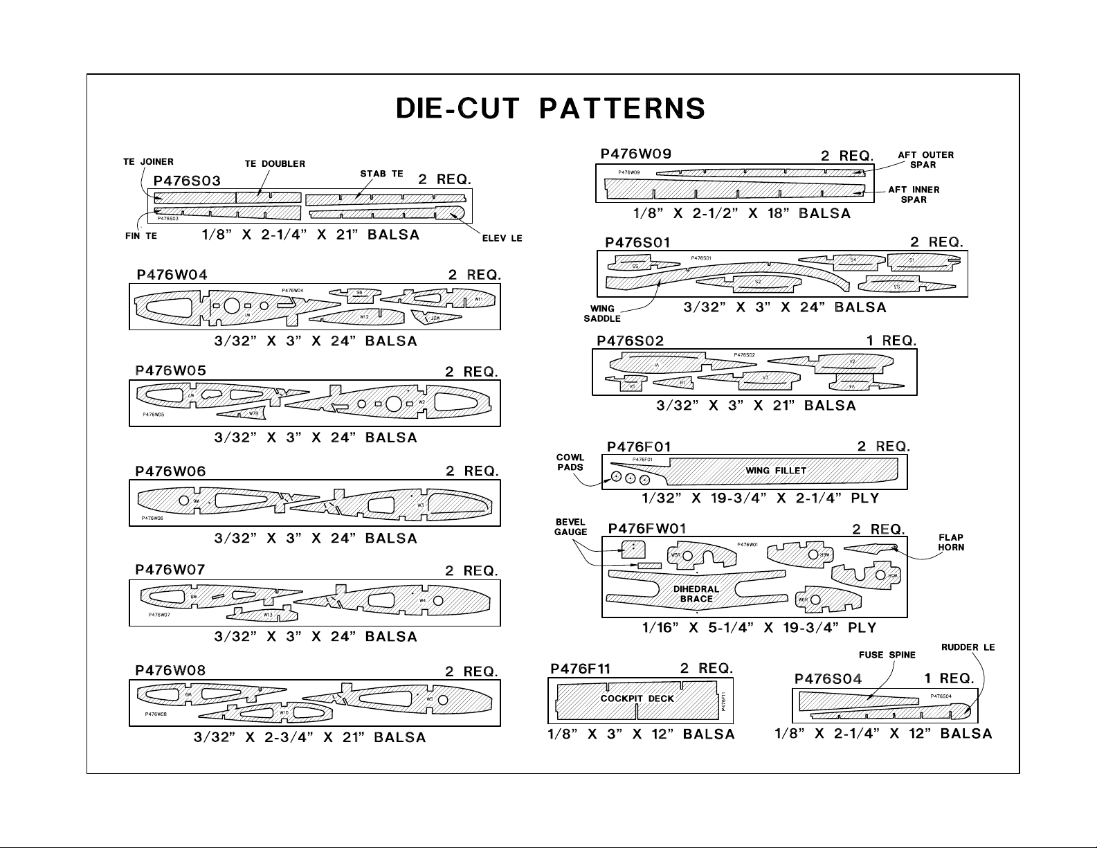
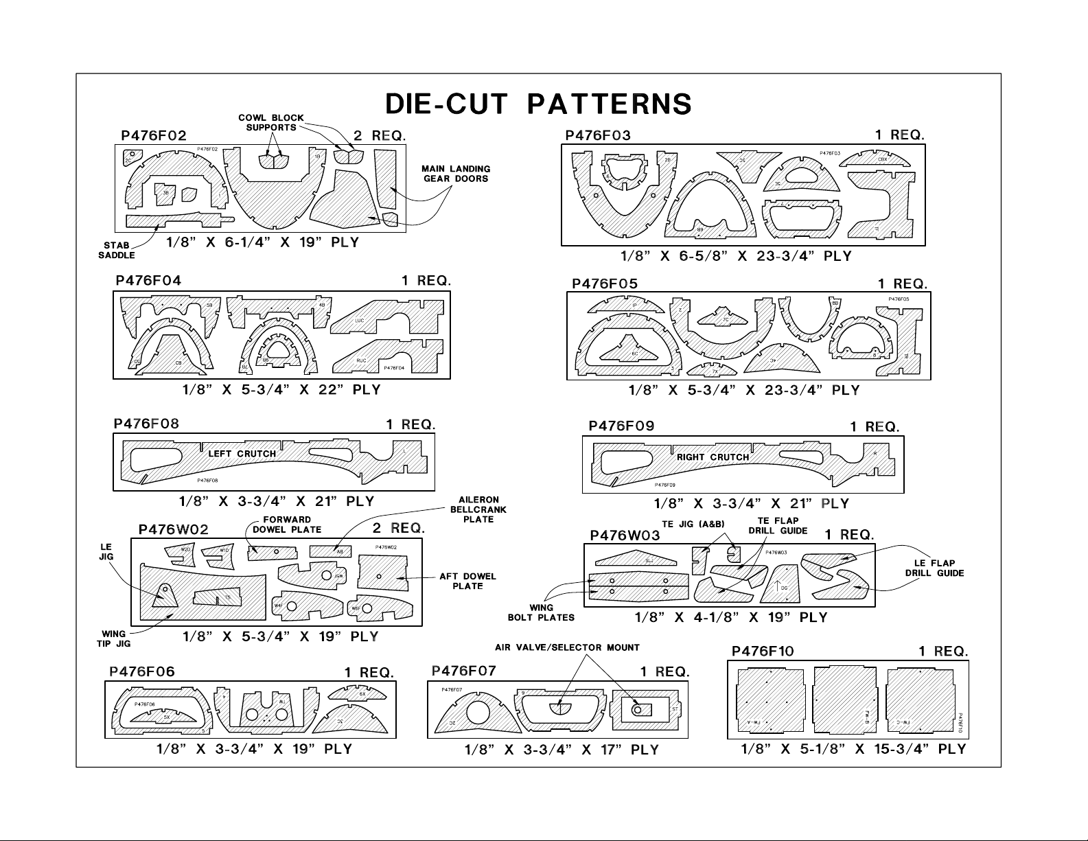
Die-Cut Patterns Page ...................................7-8
Common Abbreviations Used in the
Book and on the plans.......................................9
Metric Conversion Chart....................................9
Types Of Wood..................................................9
Get Ready to build.............................................9
Build the Tail Surfaces .......................................9
Build the stabilizer and elevators.......................9
Build the fin and rudder ...................................13
Build the Fuselage............................................15
Top Frame Assembly ......................................15
Razorback....................................................16
Bubble Canopy.............................................17
Glue the stabilizer and fin to the fuselage... 18
Complete The Fuse Top Razorback ............19
Complete The Fuse Top Bubble Canopy.....20
Final fit the canopy Razorback.....................20
Final fit the canopy Bubble Canopy .............20
Final steps before framing the lower fuse........21
Frame the fuse bottom ....................................21
Tail Gear Installation ...................................22
Fit the intercooler air exits............................24
Sheet the fuse bottom..................................25
Install the engine .............................................26
Install servo tray ..............................................27
Build the wing....................................................28
Preparation......................................................28
Retract modification for Century Jet Retracts..28
Build the wing panels.......................................29
Join the wing panels........................................33
Preparations before adding bottom
wing sheeting...................................................34
Sheet the bottom of the wing...........................34
Prepare the wing for the top sheeting..............35
Sheet the top of the wing.................................37
Build the flaps..................................................38
Fit the flaps......................................................39
Build the ailerons.............................................40
Mount the wing to the fuse...............................41
Build the wing fillet...........................................42
Build the wing belly pan...................................43
Sheet the belly pan..........................................44
Build and fit the cowl........................................45
Finish preparation.............................................46
Final sanding ..................................................46
Fuelproofing.....................................................46
Balance the airplane Laterally.........................46
Finishing............................................................46
Covering..........................................................46
Recommended Covering Sequence................47
Apply the decals..............................................47
Apply panel lines to the model.........................48
Painting............................................................48
Hinging ............................................................48
Final Assembly..................................................49
Retracts...........................................................49
Cockpit finishing ..............................................50
Optional cockpit interior...................................50
Add the molded scale details...........................50
Install receiver, switch and battery ..................51
Final hookups and checks...............................51
Control surface throws.....................................51
Balance your model.........................................52
Preflight..............................................................52
Charge batteries..............................................52
Find a safe place to fly.....................................52
Ground check the model .................................52
Range check your radio...................................52
Engine safety precautions...............................52
AMA Safety code...............................................53
Flying..................................................................53
Takeoff.............................................................53
Flying...............................................................54
Landing............................................................54
Three-view drawing – Back cover
-2-
TABLE OF CONTENTS
Inch Scal
e
0" 1" 2" 3" 4" 5" 6" 7"
0 10 20 30 40 50 60 70 80 90 100 110 120 130 140 150 160 170 180
Metric Scale
Page 3

PROTECT YOUR MODEL,
YOURSELF & OTHERS – FOLLOW
THIS IMPORTANT SAFETY
PRECAUTION
Your P-47 Thunderbolt is not a toy, but rather
a sophisticated, working model that functions very
much like an actual airplane.
Because of its performance, the Thunderbolt, if
not assembled and operated correctly, could
possibly cause injury to yourself or spectators and
damage property.
To make your R/C modeling experience
totally enjoyable, we recommend that you get
experienced, knowledgeable help with
assembly and during your first flights. You’ll
learn faster and avoid risking your model before
you’re truly ready to solo. Your local hobby shop
has information about flying clubs in your area
whose membership includes qualified instructors.
You can also contact the national Academy of
Model Aeronautics (AMA), which has more than
2,300 chartered clubs across the country. Through
any one of them, instructor training programs and
insured newcomer training are available.
Contact the AMA at the address or toll-free
phone number below:
Academy of Model Aeronautics
5151 East Memorial Drive
Muncie, IN 47302-9252
Telephone: (800) 435-9262
Fax: (317) 741-0057
INTRODUCTION
Thank you for purchasing the Top Flite
GOLD
EDITION
P-47 Thunderbolt.
The P-47 has long been recognized as an
excellent modeling subject. The wing plan form,
long tail moment and generous tail areas give the
P-47 modeler an excellent starting point. Top Flite
builds on these features with custom airfoils, 2-1/2
degrees of washout in the wing and 2-1/2 degrees
of right thrust. Top Flite’s advanced 3-D computer
engineering and interlocking construction
techniques combined with additional wing sheeting
jigs help you build a straight, lightweight model.
The result is a model warbird with exceptional
flight characteristics. The Top Flite P-47D is
smooth and forgiving both around the runway and
in high speed, high “G” flight.
Although this is a scale warbird with plenty of
detail, the builder can expect surprising results
because both the wing and fuse structure frame
up so fast. There is lots of sheeting to do over the
quickly framed structure but patterns are provided
with hints on how to prepare the sheets. When you
show up at the flying field with the Top Flite Gold
Edition P-47 your friends will see an “all out,” scale
warbird but you’ll recall a straightforward building
project with no complications (but you can keep
that a secret). Top Flite’s CAD designed structure
with interlocking parts and traditional wood
construction make this possible.
ABOUT THE AIRFOILS
Top Flite Design Engineer, David J. Ribbe,
and Low Speed Airfoil Expert, Dr. Michael Selig,
sat down over pizza to discuss what areas of the
model aircraft market could benefit from better
airfoils. One area that was identified was model
warbirds as they tend to have more wing taper
and higher wing loading than most sport/aerobatic
models. A warbird would benefit from a set of
airfoils that had better lift for a slower stall speed
and smooth, gentle stall characteristics.
Dave set out to develop a list of parameters;
things such as... stall speed, root chord, tip chord
and thickness, while making sure there would be
adequate room for retracts, compatibility with flaps,
spars, etc. These restraints were sent to Mike, so
he could design an airfoil around them. Mike used
a computer, with the latest low speed airfoil design
code to fine tune each airfoil’s shape.
The result is a root (S8036) and tip (S8037)
airfoil specifically designed for the needs of a
warbird like the P-47. We couldn’t be happier with
the results.
Please inspect all parts carefully before
starting to build! If any parts are missing, broken
or defective, or if you have any questions about
building or flying this model, please call us at
(217) 398-8970 and we’ll be glad to help. If you
are calling for replacement parts, please look up
the part numbers and the kit identification
number (stamped on the end of the carton) and
have them ready when calling.
PRECAUTIONS
1. You must build the plane according to the
plans and instructions. Do not alter or modify
the model, as doing so may result in an unsafe or
unflyable model. In a few cases the plans and
instructions may differ slightly from the
photos. In those instances you should assume
the plans and written instructions are correct.
2. You must take time to build straight, true
and strong.
3. You must use a proper R/C radio that is in firstclass condition, the correct-sized engine and
correct components (fuel tank, wheels, etc.)
throughout your building process.
4. You must properly install all R/C and other
components so that the model operates properly
on the ground and in the air.
- 3 -
Page 4

5. You must test the operation of the model
before the first and each successive flight to
insure that all equipment is operating and you
must make certain that the model has remained
structurally sound. Be sure to check external
nylon clevises often and replace them if they show
signs of wear.
6.You must fly the model only with the
competent help of a well-experienced R/C pilot if
you are not already an experienced R/C pilot at
this time.
Remember: Take your time, follow directions to
end up with a well-built model that is straight
and true.
to install retracts, there are the two types – wireand-coil or rigid struts with an oleo. Standard
wire struts absorb more shock on rough landings
and are less stressful to the airframe while the
oleo struts offer greater scale appearance. The
standard setup uses the Robart 606 HD
pneumatic system with 3/16” wire. Robart 650
oleo struts may be used and can be purchased
separately. Century Jet Models also offers the
TF P-47 pneumatic retract package with oleo
struts. See the “Other Items Required” section
and the “Retract Installation” section of the
manual for more information.
WHEEL SELECTION
Scale tire size for the P-47 is over 4" but we
recommend 3-1/2" wheels. 3-3/4" Wheels will
retract into the wing if extra care is taken
during construction.
FLAPS
This model is designed to incorporate scale
flaps; however, be assured that flaps are
optional and not necessary for an excellent
flying experience. The only difference is, without
flaps, the takeoff roll is a little longer and the
landing speed is slightly faster.
The flaps are not difficult to assemble, but
they do require good craftsmanship if they are to
fit well. They add nicely to the model’s flight
characteristics and scale appearance. Only
slight trim correction is needed when flaps are
deployed with the recommended throws. Flaps
add drag and lift to the model on landing
approaches, which gives the plane a very
steady, locked-in feel. The flaps require one
extra channel, a Y-harness and two standard
servos. They are a highly recommended
fun
option for those who wish to install them. More
information on the use of the flaps may be found
in the “Flying” section.
A .61-size Schnurle-ported engine will also provide
plenty of power for your P-47 –
especially if mostly
scale flying is in your repertoire. 1.20 4-stroke
engines should be reserved for proficient flyers
who can handle a model with a higher wing
loading and are used to the high torque
tendencies of such engines (lots of right rudder
on takeoff).
The included adjustable engine mount will
hold a range of engines from a .61 2-stroke
through 1.20 4-stroke.
A special Top Flite header and muffler is
available that will fit inside your cowling. They
are designed for 2-stroke engines as used on
our prototype:
Header for O.S .61SF (TOPQ7920)
Header for Super Tigre S61K-S75K (TOPQ7925)
Header for Super Tigre G75 (TOPQ7926)
Muffler for above (TOPQ7915)
RAZORBACK OR BUBBLE
CANOPY VERSION
Your Top Flite Gold Edition P-47D
Thunderbolt kit includes the parts and
instructions to build either the P-47D-23 known
as the “Razorback,” or the P-47D-25 “Bubble
Canopy” version. However, only the Razorback
canopy is included in the kit so if you decide to
build the Bubble Canopy version, all you need to
do is purchase the canopy set, which is offered
separately (TOPA1616). You do not need to
make this decision until about halfway through
fuselage construction.
RETRACTS OR FIXED GEAR
The choice of retractable or fixed landing
gear is yours. Retracts, once again, add to the
“presence” of your model in the air and really get
the attention of fellow modelers (and spectators).
Instructions are included for either option and
are quite detailed for retract installation so no
difficulty should be expected. Should you decide
ENGINE SELECTION
The recommended engine range is as follows:
.61 to .90 cu. in. 2-stroke
.91 to .120 cu. in. 4-stroke
The P-47 Thunderbolt will fly well with any of the
recommended engines. The 4-stroke engines and
most .90 2-stroke engines will turn a larger prop at
lower rpm’s. This is often desirable for scale
realism. If you use a .61 2-stroke, a Schnuerleported engine is preferred. The prototype P-47,
weighing 10 pounds with all of the options including
flaps, retractable landing gear and a releasable 108
gallon (scale of course) drop tank, was first flown
with the Super Tigre S-75K. This proved to be the
ideal size for a two-stroke power plant – large
enough to provide plenty of reserve power for
aerobatics and sport flying, yet small enough to
represent scale speeds when throttled back a little.
DECISIONS YOU MUST MAKE EARLY
IN THE BUILDING PROCESS
NOTE: We, as the kit manufacturer, can provide
you with a top quality kit and great instructions,
but ultimately the quality and performance of
your finished model depends on how you build
it. Therefore, we cannot in any way guarantee
the performance of your completed model, and
no representations are expressed or implied as
to the performance or safety of your completed
model aircraft.
- 4 -
Page 5
OTHER ITEMS REQUIRED
Item numbers (GPMQ4130) are suggested part
numbers recognized by distributors and hobby
shops and are listed for your ordering
convenience. TOP is the Top Flite brand, GPM is
the Great Planes brand and HCA is the prefix for
the Hobbico brand.
❏ 4 to 7 channel radio with 5 to 8 servos.
❏ 6" Aileron servo extension cords – Futaba J
HCAM2000
❏ Engine (see page 4)
❏ Propellers (see engine instruction manual for
proper propeller sizes)
❏ 14 oz. Fuel Tank – GPMQ4106
❏ 3-1/2" Main Wheels – Robart ROBQ1535
❏ 1-1/4" tailwheel – GPMQ4242
❏ 3/16" Wheel Collars – GPMQ4308, pkg. of 4
❏ 3/32" Wheel Collars – GPMQ4302, pkg. of 4
❏ Top Flite MonoKote covering, 3 rolls (see
Finishing
section)
❏ Paint (see
Finishing
section)
❏ Medium Silicone Fuel Tubing – GPMQ4131
❏
1/2" Latex Foam Rubber Padding – HCAQ1050
❏ Flexible cable throttle pushrod – GPMQ3700
-or-
❏ 1/16" x 12" threaded-end pushrod
OPTIONAL
For Flaps:
❏ Hobbico “Y” Harness (Fut J) – HCAM2500
-or-
❏ Futaba Dual Servo Extension – FUTM4130
❏ 6 Pcs. Robart #309 Super Hinge Points large
– ROBQ2509, pkg. of 6
For Retractable Landing Gear:
❏ Robart #606 85° HD Pneumatic Retracts –
ROBQ0006
❏ Robart #188 Air Control Kit – ROBQ2388
❏ Robart #164G Hand Pump – ROBQ2363
❏ 3 Pcs. Robart #190 Quick Connectors
– ROBQ2395 pkg. of 2
NOTES FOR THE COMPETITION-
MINDED MODELERS AND
DEVIATIONS FROM SCALE
The P-47D-23 Razorback was instrumental
in turning the tide of WWII. It was escorting
bombers to targets before the longer ranged
Mustangs appeared in significant numbers.
The “Bonnie” trim scheme shown on the box
was done with MonoKote film and the decals
supplied in the kit.
The main landing gear is simplified. They
pivot at the scale location, but the wells are
moved forward, slightly ahead of the main spar.
The model’s tires (3-1/2" to 3-3/4") are smaller
than scale in order to fit into the space provided,
but the stance on the ground is scale.
The elevator and rudder hinge lines have
been modified in order to simplify assembly and
use standard model hinging techniques.
The true scale factor of the Top Flite P-47 is
1:7.77, or approximately 1/8.
DOCUMENTATION
Following are some of the books that are
available showing various details of the P-47:
Thunderbolt – A Documentary History of the
Republic P-47, Roger A. Freeman.
Contains the excellent 5-view drawings that
the Top Flite P-47 was designed around. It also
contains many photos and historical information.
P-47 Thunderbolt – In Action, Squadron/Signal
Features “Bonnie” on the cover and includes
3-views and many photos and illustrations.
TOP FLITE SCALE ACCESSORIES
SCALE COCKPIT INTERIOR:
Another exciting
option made specifically for your Top Flite Gold
Edition P-47 is the Scale Cockpit Interior. It goes
without saying (we’ll say it anyway) that a full
cockpit interior really adds to the realism and
overall appearance of your model. Since it is
made for the P-47, installation is easy. This can
be done about 3/4 of the way through fuselage
construction or it may be saved until after
covering is finished. We urge you to take
advantage of this option as rarely do you find
such details offered by the manufacturer
specifically for their own model. Instructions for
painting and finishing are included with the
cockpit kit (TOPQ8405).
REPLICA RADIAL ENGINE:
A final touch of
scale realism is possible by installing the
specially designed 9-cylinder replica radial
engine inside the cowl. The replica radial adds
significantly to the look of the model and, when
backed up by 1/8" lite-ply, doubles as a cooling
baffle for the real engine. Made from vacuumformed ABS, the replica radial is easy to
assemble and can be modified to suit any
engine installation (TOPQ7902).
DROP TANKS:
To increase its range, the P-47
used one or more drop tanks. With the 108
gallon “Paper” Tank (TOPQ7899) and/or the 75
gallon Tank (TOPQ7900) you can give the P-47
that business-like “loaded down” look and add
even further to the scale realism. The release
mechanism is included with the tanks so they
can be made releasable in flight or may be
manually disconnected. Scale pylons are
included for the outboard Wing Tanks.
- 5 -
Page 6
❏
Robart #650 Straight Robostruts – ROBQ1700
(optional)
❏ Robart #189Air Restrictor Set – ROBQ2389
(optional)
-or-
❏ Century Jet Models Retracts
❏ Top Flite Header & In Cowl Muffler (See page
4 for description)
❏ Scale Pilot figure (1/6 Scale Williams Brothers
WBRQ2472 Military or WBRQ2476 Standard)
❏ Fuel Filler Valve – GPMQ4160
❏ Fuel Filter – GPMQ4250
❏ Top Flite 75 Gal. Drop Tank(s) – TOPQ7900
❏ Top Flite 108 Gal. Drop Tank – TOPQ7899
❏ Sullivan #507 Gold-N-Rod for releasable drop
tanks – SULQ3007
❏
Screw-Lock Pushrod Connectors – GPMQ3870
(optional)
❏ Switch & Charge Jack Mount – GPMM1000
❏ Top Flite Cockpit Interior Kit – TOPQ8405
❏ Top Flite 1/8th Scale Replica Radial Engine –
TOPQ7902
❏ #4x1/2 Button head screw – GPMQ3124
SUGGESTED SUPPLIES AND TOOLS
We recommend Top Flite Supreme™CA and Epoxy
❏ 2 oz.CA (Thin) – TOPR1003
❏ 2 oz. CA+ (Medium) – TOPR1008
❏ 1 oz. CA- (Thick) – TOPR1011
❏ CA Applicator Tips – HCAR3780
❏ CA Accelerator – TOPR1025
❏ 6-Minute Epoxy – TOPR1040
❏ 30-Minute Epoxy – TOPR1043
❏ Wood Glue – GPMR6160 (optional)
❏
Pacer Z-560 Canopy Glue – PAAR3300 (optional)
❏ Hand or Electric Drill
❏ Silver Solder w/flux – GPMR8070
❏ Sealing Iron – TOPR2100
❏ Heat Gun – TOPR2000 (optional)
❏ Hot Sock – TOPR2175 (optional)
❏ Trim Seal Tool
™
– TOPR2200 (optional)
❏ #1 Knife handle – XACR4305
❏ #11 Blades (100 qty.) – HCAR0311
❏ Single Edge Razor Blades – HCAR0312
❏ Razor Saw
❏ Common pliers
❏ Screwdrivers (Phillips and flat head)
❏ Robart Super Stand – ROBQ1401
❏ T-Pins – HCAR5100 small, HCAR5150
medium, HCAR5200 large
❏ Straightedge–Fourmost Non-Slip – FORR2149
❏
3/4 oz. Fiberglass Cloth – HCAR5000 (Optional)
❏ Masking Tape
❏ Sandpaper (see Hot Tip on this page)
❏ Easy-Touch
™
Bar Sanders – GPMR1670
❏ Waxed Paper
❏ HobbyLite
™
Balsa Filler – HCAR3401
❏ 1/8", 3/16", 1/4", 7/32" brass tube (optional)
❏ Tap wrench
❏ 1/4-20 Tap w/drill bit – GPMR8105
❏ 8-32 Tap w/drill bit – GPMR8103
❏ Denatured or Isopropyl Alcohol
❏ Dremel
®
Moto-Tool™or similar w/sanding
drum, cutting burr, cut off wrench (optional)
❏ 9/64" ball end hex wrench – GPMR8004
❏ Kyosho
®
Curved Scissors – KYOR1010
❏ Razor Plane – MASR1510
❏ String
❏ Auto body filler (Bondo
®
or similar)
❏ 3M #75 Repositionable Spray Adhesive
Drill Bits: ❏ 1/16" ❏ 3/16"
❏ 5/64" ❏ 7/32"
❏ 1/8" ❏ 15/64"
❏ 9/64" ❏ 1/4"
❏ 17/64"
On our workbench, we have four 11" Great
Planes
®
Easy-Touch™Bar Sanders, equipped
with #50, #80, #150 and #220-grit sandpaper.
This setup is all that is required for almost any
sanding task. Custom sanding blocks can be
made from balsa for sanding hard to reach
spots. We also keep some #320-grit wet-or-dry
sandpaper handy for finish sanding before
covering.
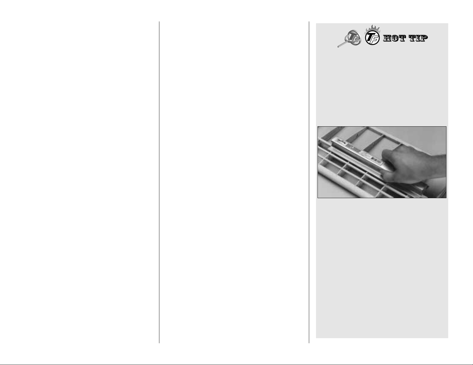
Great Planes Easy-Touch Bar Sanders are
made from lightweight extruded aluminum and
can be found at most hobby shops. They are
available in two sizes – 11" (GPMR6170) for
most general purpose sanding and 22"
(GPMR6172) for long surfaces such as wing
leading edges. We recommend using the 2"
wide self adhesive sandpaper sold in 12' rolls by
Great Planes. Standard sandpaper can be
attached by gluing it to the sander with brush-on
rubber cement. Apply the rubber cement to both
the bottom of the sander and the back of the
sandpaper. When both surfaces are dry to the
touch, press the sandpaper firmly onto the
sander. Spray adhesive can be used for this
purpose but it’s much harder to remove the
sandpaper when you need to replace it. Use
a knife blade for cutting sandpaper, not your
good scissors!
- 6 -
Page 7
- 7 -
Page 8
- 8 -
Page 9
COMMON ABBREVIATIONS USED IN
THIS BOOK AND ON THE PLANS:
Deg = Degrees
Fuse = Fuselage
LE = Leading Edge (front)
LG = Landing Gear
Lt = Left
Ply = Plywood
Rt = Right
Stab = Stabilizer
TE = Trailing Edge (rear)
" = Inches
Elev = Elevator
METRIC CONVERSION CHART:
INCHES X 25.4 = MM (CONVERSION FACTOR)
1/64"= .4 mm
1/32"= .8 mm
1/16"= 1.6 mm
3/32"= 2.4 mm
1/8" = 3.2 mm
5/32"= 4.0 mm
3/16"= 4.8 mm
1/4" = 6.4 mm
3/8" = 9.5 mm
1/2" = 12.7 mm
5/8" = 15.9 mm
3/4" = 19.0 mm
1" = 25.4 mm
2" = 50.8 mm
3" = 76.2 mm
6" = 152.4 mm
12" = 304.8 mm
18" = 457.2 mm
21" = 533.4 mm
24" = 609.6 mm
30" = 762.0 mm
36" = 914.4 mm
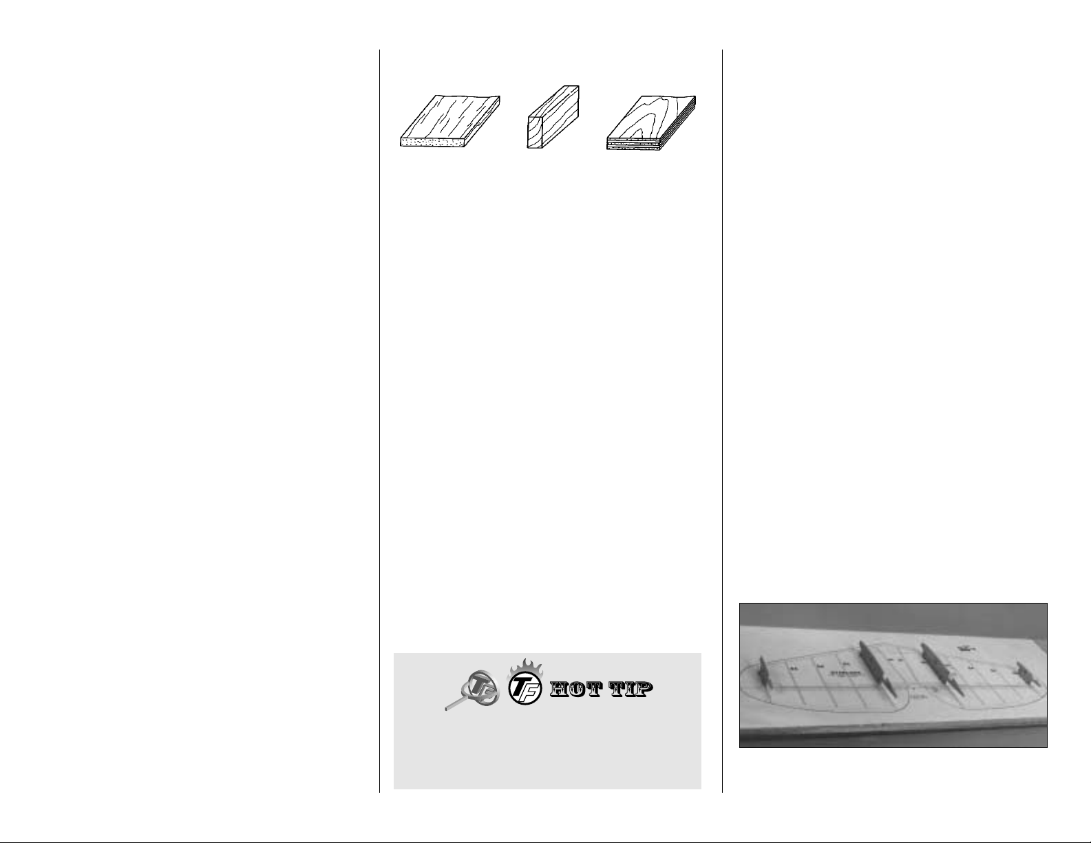
TYPES OF WOOD:
GET READY TO BUILD
❏ 1. Unroll the plan sheets. Reroll the plan
inside-out to make it lie flat.
❏ 2. Remove all parts from the box. As you do,
determine the name of each part by comparing it
with the plan and the parts list included with this
kit. Using a felt-tip or ball-point pen, lightly write the
part name or size on each piece to avoid
confusion later. Use the die-cut patterns shown on
pages 7 and 8 to identify the die-cut parts and
mark them before removing them from the sheet.
Stock up on scrap balsa by saving the large parts
of the remainder of the die-cut sheets after the
parts have been removed.
If any of the die-cut parts are difficult to remove, do
not try to force them! Instead, cut around
the parts with a hobby knife. After removing the
die-cut parts, use your Easy-Touch or sanding
block to lightly sand the edges to remove any
die-cutting irregularities.
❏ 3. As you identify and mark the parts, separate
them into groups, such as fuse (fuselage), wing,
fin, stab (stabilizer) and hardware.
BUILD THE TAIL SURFACES
BUILD THE STABILIZER AND ELEVATORS
❏ 1. Always build on a flat surface. Refer to the
plans to identify the parts and their locations.
The
plans may be cut apart if space is a problem.
Tape
them to your building board and cover them with
waxed paper.
❏ 2. Remove both sets of the die-cut 3/32" balsa
stab Ribs S-1 through S-6 and the die-cut 1/8"
balsa stab Trailing Edges (TE’s) and TE
Doublers. There is a Jig Tab on the bottom edge
of each of the ribs. If any of these break off,
carefully glue them back on with thin CA. Lightly
sand any imperfections. Use a pen to mark the
extensions of the bottom edge of the ribs across
the fore and aft ends of the jig tabs. These marks
will help when you trim off the jig tabs later.
❏ 3. Cut the Stab Leading Edges (LE’s) 1/4"
longer than shown on the plans from two pieces of
1/4" x 11-7/8" tapered balsa stock.
HINT: Bevel the front edge of the ribs to match the
sweep angle of the LE. This will give you a better
fit and a stronger glue joint.
❏ 4. Pin only the S-2 ribs and the S-6 ribs to the
building board over their locations on the plan.
Zipper-top food storage bags are handy to store
your small parts as you sort, identify and
separate them into sub-assemblies.
- 9 -
Balsa Basswood Ply
Page 10
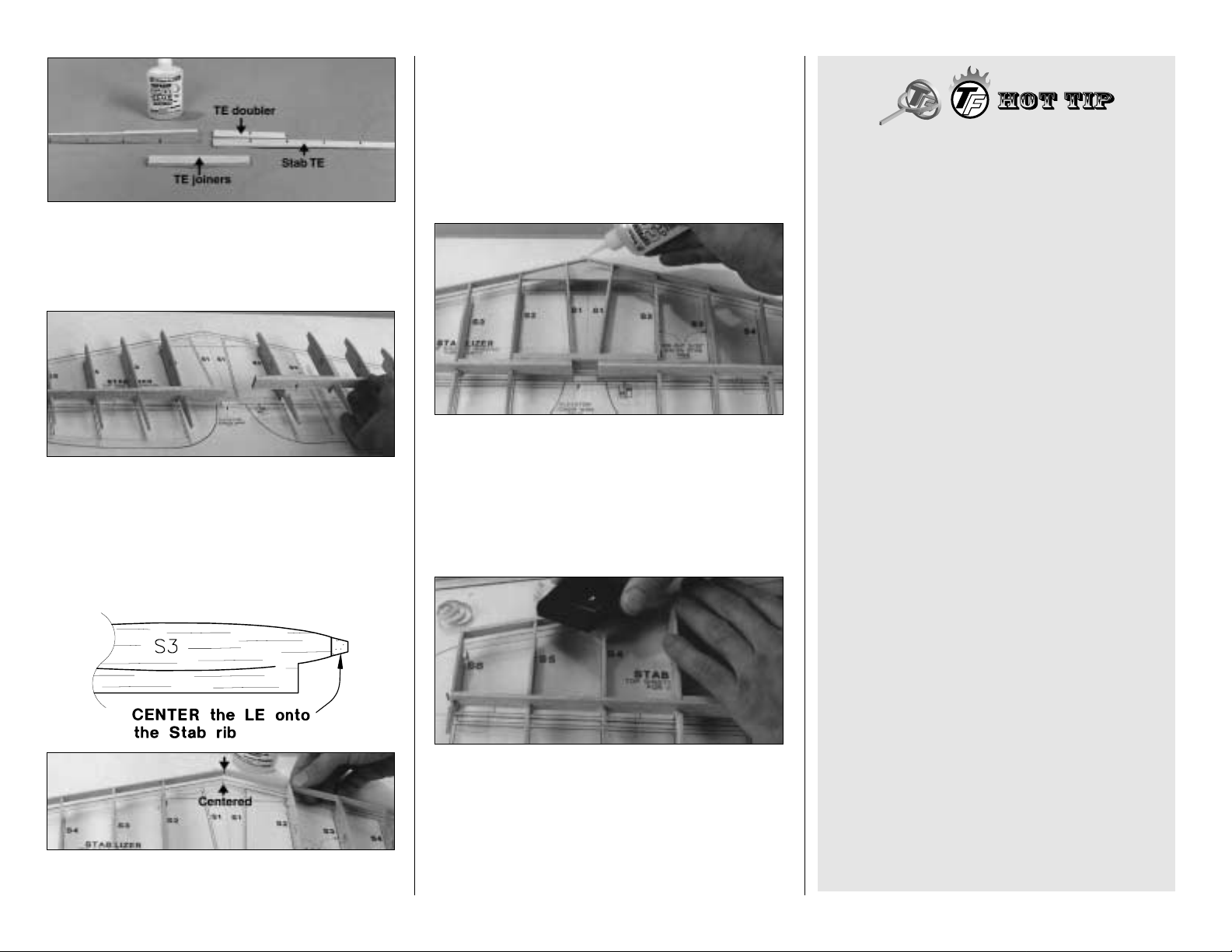
❏ 5. With the notch in one of the stab TE’s aligned
with the notch in a stab TE doubler, glue the pieces
together. Do the same with the other stab TE and
doubler. Make a right and a left half. Glue the
die-cut 1/8" balsa stab TE Joiners together.
❏ 6. Without using any glue, install ribs S3, S4
and S5 in the notches in the TE’s, then fit the
TE’s to ribs S6 and S2 previously pinned to the
building board.
During the next step make certain the jig
tabs on the ribs are contacting the building
board and the ribs are perpendicular to the
building board.
❏ 7. Vertically centered, glue one of the stab LE’s
to ribs S6 and S2, then do the same with the other
LE. Glue both TE’s to all the ribs then glue the rest
of the ribs to the LE.
❏ 8. Use thick CA to glue the TE joiner to the TE’s
making sure the jig tabs on the ribs are
contacting the building board. Wipe away
excess glue between the TE’s.
❏ 9. Trial fit both S1 ribs
without
the die-cut 1/8"
plywood LE Joiner. After any required adjustments
have been made to the S1’s, trial fit them
with
the
LE joiner. Make further adjustments if required then
securely glue the assembly in position. Use CA to
reinforce any glue joints that don’t look strong.
❏ 10. Prepare the top of the stab for sheeting. Use
a razor plane and a sanding block to trim the top
surface of the LE (particularly toward the tip) until it
is even with the ribs. Sand the TE to smoothly
blend with the ribs. The stab frame may be
removed from the building board for this step but
must be repinned to the flat building board to apply
the skins.
HOW TO MAKE WING AND
STAB SKINS
(Also see additional Hot Tip on page 34)
A. Wherever practical, prejoin the balsa sheets
to make a “skin” before attaching them to the
structure.
B. Many modelers like to sort the wood so they
can put the best wood with the most even grain
structure on the
top
of the wing and stab.
C. Make your skin larger than needed to allow
for misalignment. On a large surface like the
wing, 3/8" extra is suggested.
D. To make skins, the following steps are
suggested:
1. True up the edges of the sheets with a
metal straightedge and a sharp hobby knife or
an Easy-Touch Bar Sander.
2. Test fit the sheets together to make sure
they match well.
3. Method “A”: The fastest method for gluing
the sheets together is with thin CA over a flat
surface covered with waxed paper. A quick wipe
of the joint with a fresh paper towel will remove
most of the excess glue and make sanding
easier. Mark the poorest surface with an “I” as
the inside of the sheet.
Method “B”: An alternate method for gluing
the pieces that make up a stab or fin skin is to
glue them together with aliphatic resin (white
glue). Aliphatic resin sands much easier than
CA so your skins won’t get too thin from over
sanding. Use masking tape to hold the sheets
together until the glue cures – usually in about
thirty minutes.
- 10 -
Page 11
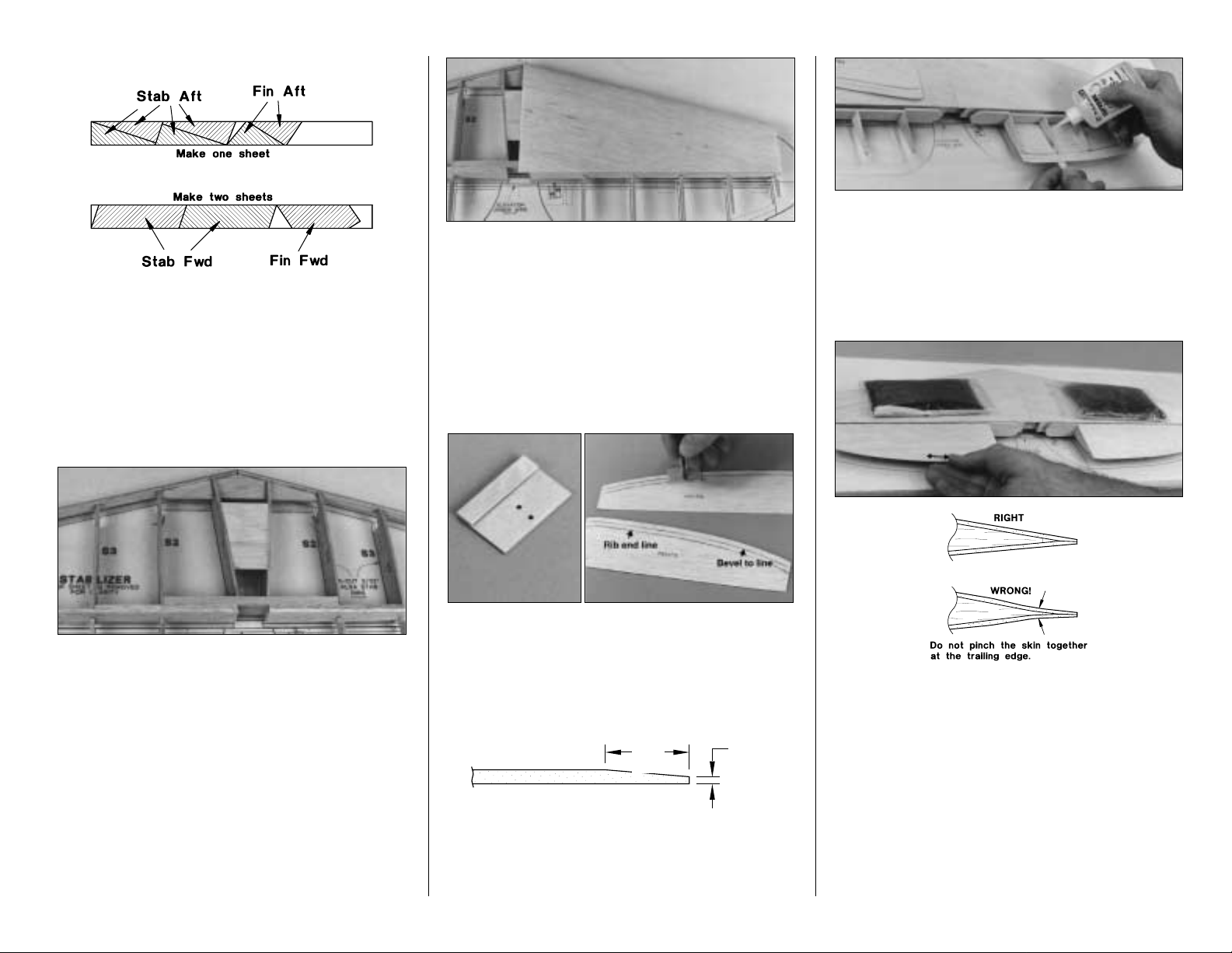
❏ 11. Make the skins for the stabs and fin using
three 1/16" x 3" x 36" balsa sheets. See the sketch
for the correct layout on the sheets. Refer to the
plans for the exact shapes and sizes but
remember to cut the sheets slightly oversize.
Note: The grain direction of the skins is
parallel
to the leading edges of stab and fin.
❏ 12. Cut a 2-1/2" wide cross-grain strip from one
of the 1/16" x 3" x 36" balsa sheets used for the
stab and fin skins, cut it to fit, then glue it between
the S1 stab ribs.
Caution: If you have recently used any CA
Accelerator on the structure during previous
steps, be aware that residual accelerator may
cause the thick or medium CA you may use
during the next step to harden prematurely.
Some modelers prefer to glue the skins to the
structure with aliphatic resin. Use T-pins to
hold the skins in position until the glue cures.
❏ 13. Be certain you can remove the stab from the
building board after you glued the skins on. Apply
an even bead of medium or thick CA to the upward
facing edges of the structure. Place a skin in its
proper position and press it down firmly until the
glue has set. Repeat this step for the other
top skin.
❏ 13. Use the template provided on the wing plans
to cut four Elevator Skins from a sheet of 1/16" x
3" x 36" balsa.
❏ 14. Build the Bevel Gauge from the die-cut
1/16" plywood then drill a #48 (or 5/64") hole at
each punch mark. Use the gauge with a ball-point
pen to mark the bevel and “rib end” indication
lines on the inside surfaces of the elevator skins.
Make rights and lefts.
❏ 15. Use your Easy-Touch with fresh 150 or 220-
grit sandpaper to bevel the aft 1/4" of the elevator
skins (indicated by the aft line drawn with the
gauge) down to roughly 1/32".
❏ 16. Glue the die-cut 1/8" balsa Elevator
Leading Edges to the notches in the ribs then
glue the bottom elevator skins in position. Note:
Be sure the LE’s are parallel to the stab TE. Hint:
A stick will serve as a lever to push up the elevator
skin to the elevator leading edge while you are
gluing it.
❏ 17. Glue the top elevator skin in position.
Weights placed on the stabilizer will help hold it to
your flat building board to assure a straight, true
stab and elevators.
❏ 18.
Carefully remove the stab and elevators from
your building board. Remove the jig tabs and use a
razor saw to separate the elevators from the
stab. Use an Easy-Touch loaded with 220-grit
sandpaper to blend the ribs to the trailing and
leading edges of the stab to prepare the structure for
the bottom skins.
- 11 -
1/4"
1/32"
3/8"
1/32"
Page 12
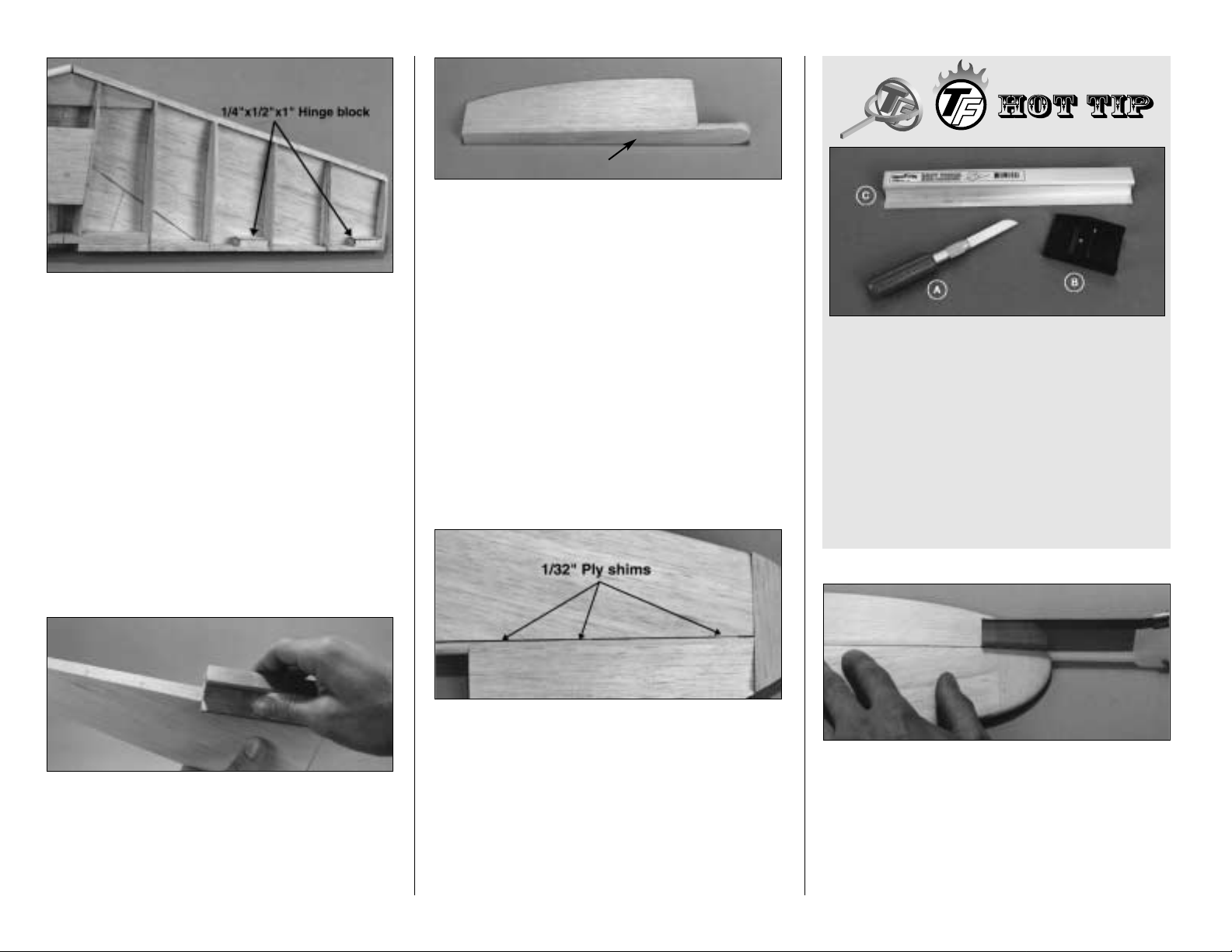
❏ 19. Cut another piece of 1/16" cross-grain
sheeting 2-1/2" long and glue it between the S1
ribs as you did in step 12. Add four 1/4" x 1/2" x 1"
Hinge Blocks to the inside of the stab trailing
edged as shown in the plans. The outer hinge
blocks will need to be trimmed to match the height
and contour of the stab TE.
❏ 20. Inspect all glue joints and add CA where
necessary. Glue the bottom stab skins just as you
did the top. A good glue joint here is important, so
apply a generous bead of thick or medium CA to
all the upward facing edges of the structure.
Remember: Residual accelerator can cause the
CA to cure prematurely. Be careful not to add
any twist in the stab as you apply the skins.
❏ 21. Use a sanding block to true up the tips of
the stab and elevators and to remove the
remnants of the ribs from the leading edges of the
elevators and the trailing edge of the stab.
IMPORTANT: Round the LE of the stab to match
the cross section on the plan.
❏ 22. Glue a 3/16" x 1" x 11-7/8" balsa Leading
Edge Cap to each elevator LE then trim to match
the length of the elevator LE. Use a razor plane,
then a sanding block to blend the top and bottom
of the leading edge cap to the skins. Round the
inboard ends to match the elevator LE.
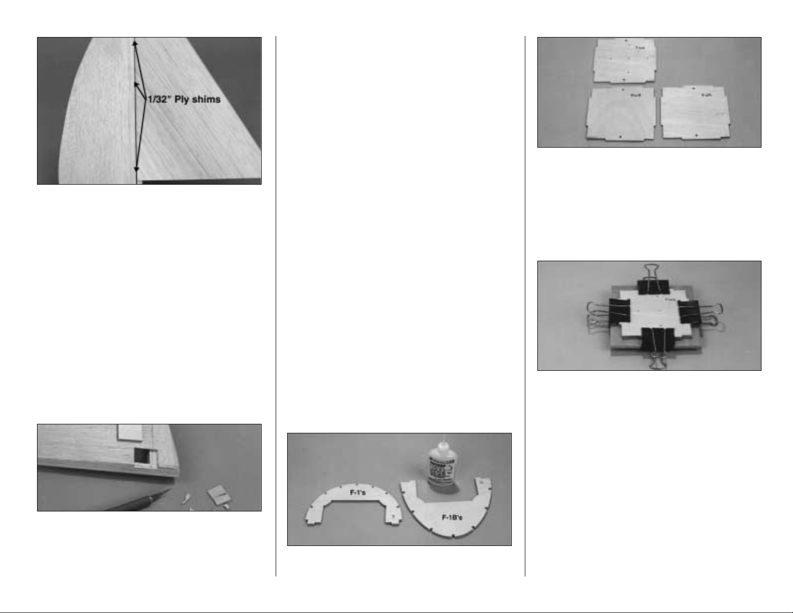
❏ 23. Tack glue three 1/32" scrap plywood shims
to the leading edge of each elevator, then tack
glue each elevator to the stabilizer with a drop of
CA on the shims. Make sure the outboard tips are
flush by sanding the edges with a sanding block
if required.
❏ 24. Noting their orientation on the plans, glue
the shaped 5/8" thick balsa Stabilizer Tips
simultaneously to the stab and elevator.
❏ 25. Use a razor plane and a sanding block to
shape and round the tips. Refer to the cross
section on the plans frequently during this process.
❏ 26. Separate the elevators from the stabilizer by
cutting the tips with a razor saw and breaking
away the tack glued 1/32" plywood shims.
Hint: Hold the razor saw close to the leading edge
of the elevators while cutting. Use a long sanding
block and 150-grit sandpaper to true the tips with
the leading edges of the elevators and the trailing
edges of the stabilizer.
SHAPING BALSA BLOCKS
The long carving blade in a heavy duty handle (A)
is the best tool to create the rough shape as a
large amount of wood can be easily removed.
Once the blocks are “roughed in,” use a razor
plane (B) to fine tune the shape. Finally, #50
coarse, #150 medium and #220 fine sandpaper on
an Easy-Touch Bar Sander will smooth out the
lines and flat spots. Don’t try to shave too much
wood at one time and inspect your progress
frequently. You can always remove wood, but it’s
difficult to put it back.
- 12 -
LE Cap
Page 13
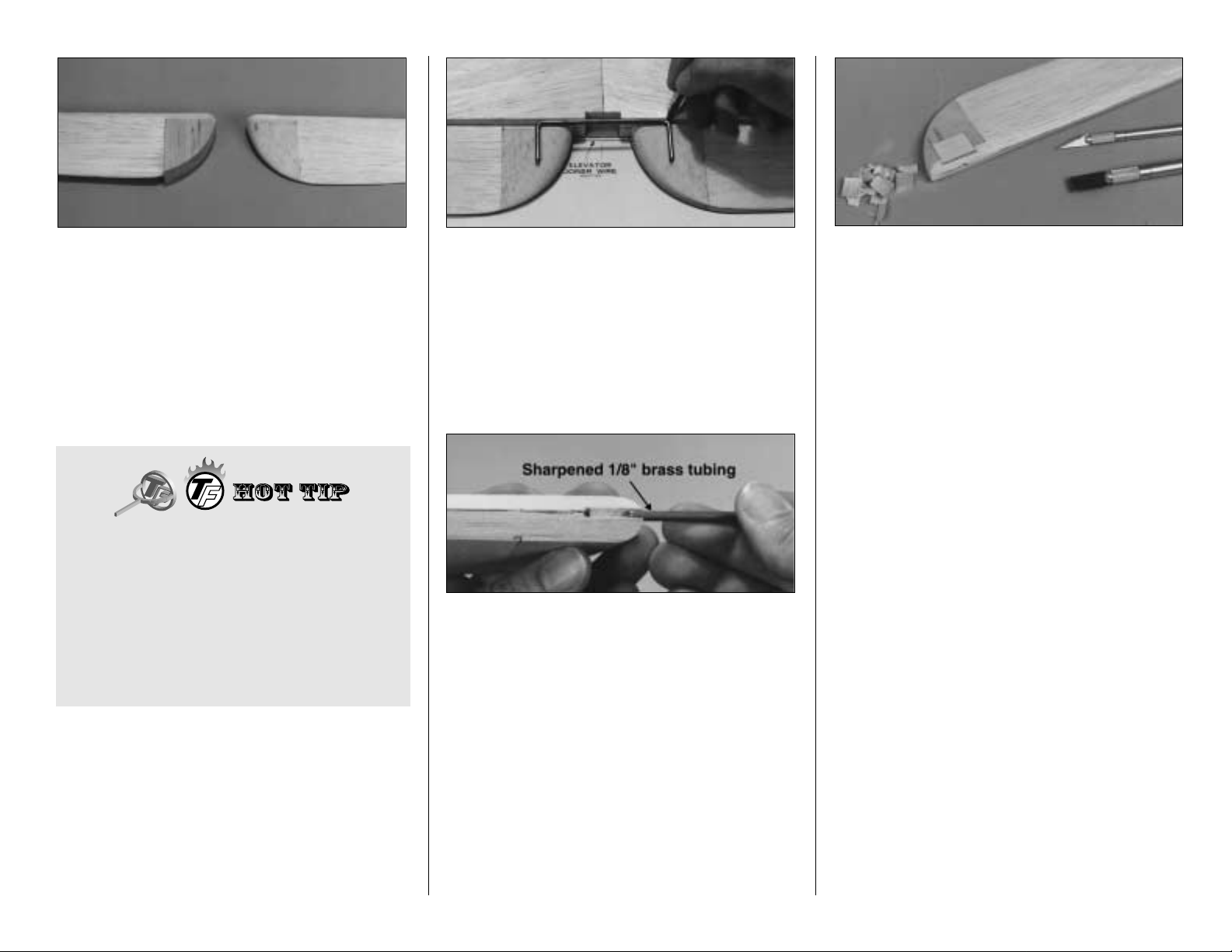
❏ 27. Glue the shaped 7/8" thick balsa Elevator
Root Blocks to the elevators then use a razor
plane and a sanding block to shape them as you
did the tips.
❏ 28. Draw centerlines on the leading edge of the
elevators and on the trailing edge of the stabilizer.
Mark the position of the hinges on the elevators
and stabilizer using the locations on the plans as
a guide.
❏ 29. Cut the hinge slots now and temporarily
install the hinges. Refer to the detailed hinging
instructions on page 48. NOTE: Do not glue the
hinges yet, but wait instead until after the
model is covered.
❏ 30. Sand the elevator LE’s to a “V” shape to
allow for the elevator travel (see the stab cross
section on the fuse plans).
❏ 31. Hold the bent 1/8" Elevator Joiner Wire up
to the elevators and mark the location of the holes
(see the plans). Remove the elevators from the
stabilizer and drill 1/8" holes in the elevators to
accomodate the joiner wire.
❏ 32. Make slots inboard of the holes to allow the
wire to be inserted into the elevators. Hint: A piece
of 1/8" brass tube sharpened at one end makes a
great gouge for cleanly removing material from the
leading edge of the elevators. Trial fit the stabilizer
to the elevators with the joiner inserted and confirm
that the elevators align with each other. Make
adjustments if required.
❏ 33. Mark the location for the 1/8" x 7/8" x 1"
plywood Elevator Horn Block on the bottom of the
right elevator. Remove material as needed to allow
the horn block to fit flush with the surface of
the elevator.
❏ 34. Glue the elevator horn block to the elevator,
then sand it so the pieces blend together.
BUILD THE FIN AND RUDDER
The Fin and Rudder are built simultaneously just
the same as the stabilizer.
❏ 1. Remove the die-cut 3/32" balsa ribs V-1
through V-5 and R-1 and the die-cut 1/8" balsa Fin
TE’s and Rudder LE. Be sure to preserve the
jig tabs.
❏ 2. Cut the fin leading edge to the exact length
shown on the plans from a piece of 1/4" x 11-7/8"
tapered balsa stabilizer LE stock. Notice that the fin
LE fits into a notch on top of F-9.
❏ 3. Slightly bevel the front edge of the ribs to
match the angle of the leading edge stock.
DRAWING CONTROL SURFACE CENTERLINES
1. Accurately measure the center point at the two
extreme ends of the surface to be marked.
2. Insert a T-pin at each of the marks.
3. Hold a straightedge against the pins, then draw
the centerline.
- 13 -
Page 14
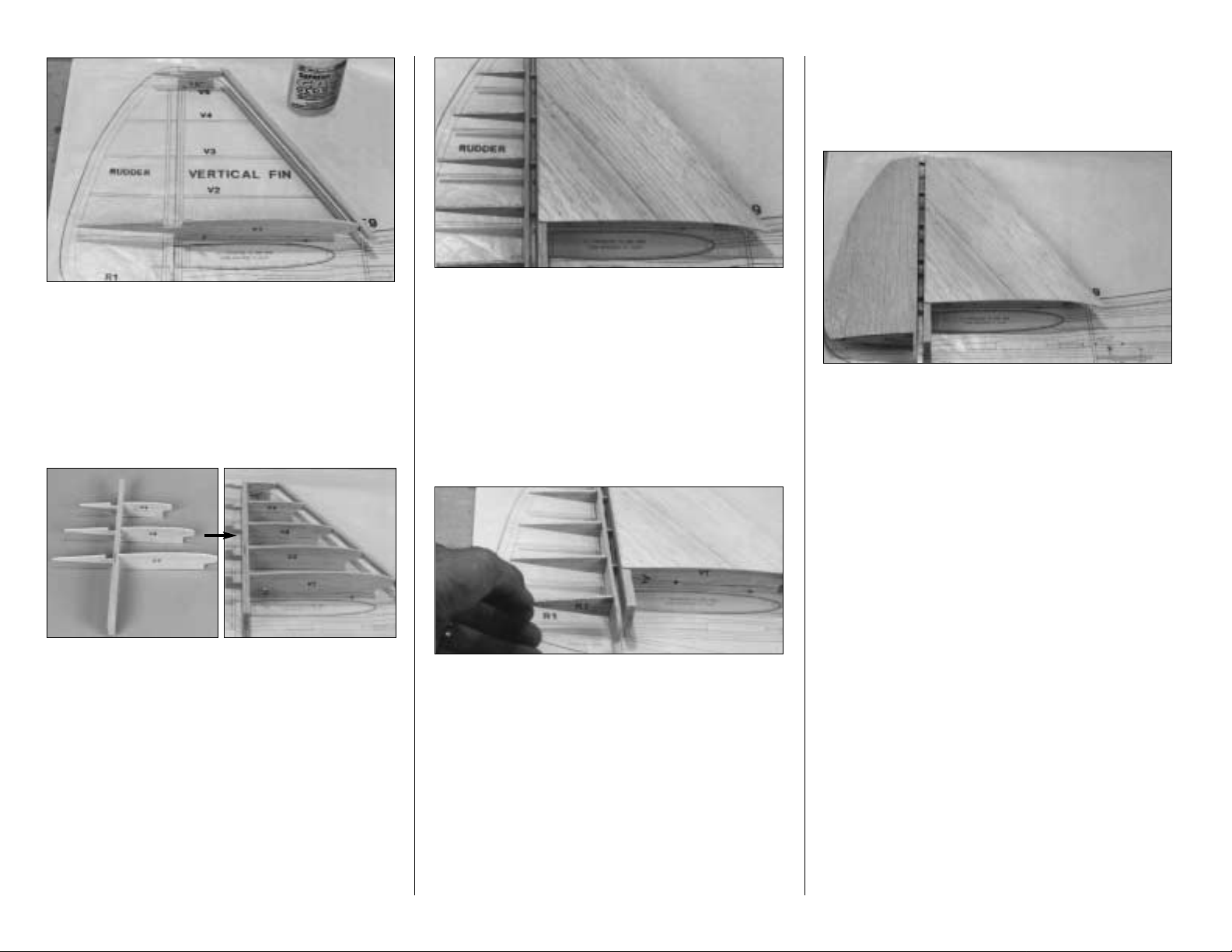
❏ 4. Cover the rudder and vertical fin portion of the
plans with waxed paper. Lay the leading edge on
the plans and mark the exact location of rib V-1
directly on it with a pen. Pin only ribs V-1 and V-5
to the building board over the plans. Vertically
center the LE on the front of the ribs and glue it
in place.
❏ 5. Laminate the two fin trailing edges to each
other with thick CA. Place the remaining ribs in the
notches of the fin trailing edge, but do not glue
them yet. Fit the assembly to the parts already on
the building board.
❏ 6. With all jig tabs contacting the building
board and the ribs vertical, glue them to the
leading edge and the trailing edge.
❏ 7. Use a sanding block and 150-grit sandpaper
to blend the LE and TE to match the ribs on the
upward facing (right) fin side.
❏ 8. Make a skin for each side of the fin using the
1/16" balsa sheet left over from the stab skins.
Make them longer than required so they extend
past V-1 about 5/8"; this will allow fitting to the stab
later. With the structure flat on the table, glue on
the right skin.
❏ 9. Trial fit the rudder LE to the notches in the
ribs and make adjustments if necessary. Glue the
rudder LE to the ribs.
❏ 10. Trial fit R-1 to the notch in the rudder leading
edge. Make sure it is square with the rudder
leading edge and in line with the other rudder ribs,
then glue it in position.
❏ 11.
Use the templates provided on the plans to
make two Rudder Skins from a 1/16" x 3" x 36"
balsa sheet. Use the bevel gauge to mark the
lines on the inside of each rudder skin, then
sand the bevel just the same as you did on the
elevator skins.
❏ 12. Glue the left rudder skin to the ribs and
leading edge of the rudder.
❏ 13. Glue the right rudder skin in position.
❏ 14. Remove the assembly from the building
board and use a razor saw to separate the rudder
from the fin. Remove the jig tabs from the fin and
blend the leading and trailing edge to the ribs to
prepare for the left side sheeting.
❏ 15. Glue the left fin skin to the fin.
❏ 16. True up the edges of the sheeting on both
the fin and rudder with a sanding block. Shape the
LE of the fin to match the cross section on
the plans.
❏ 17. Glue the shaped balsa Rudder Base and
the 1/4" x 1" x 11-7/8" Rudder LE Cap to the
rudder. Trim the LE cap to the length shown on the
plans and roughly shape the rudder base to blend
it with the rest of the rudder. Don’t completely
round the bottom of the rudder yet as this will be
done when it can be fitted to the fuselage.
- 14 -
Page 15
❏ 18. Tack glue or tape the rudder to the fin with
three 1/32" plywood shims (as we did with the
elevators). True up the tip of the fin and rudder if
necessary, then glue the shaped 5/8" balsa Fin Tip
simultaneously to the fin and rudder.
❏ 19. While the rudder and fin are still joined, use
a razor plane and a sanding block to final shape
the tip according to the plans. After shaping the
tip, separate the rudder from the fin by cutting
the tip with a razor saw and breaking off the
plywood shims.
❏ 20. Draw a centerline on the leading edge of the
rudder and the trailing edge of the fin, cut the
hinge slots, then sand the “V” on the leading edge
of the rudder.
❏ 21. Mark the location of the 1/8" x 7/8" x 1" birch
ply Rudder Horn Block on the rudder. Remove
balsa from the marked area, then glue the horn
block in position. Sand it to blend to the shape of
the rudder.
Now you have a couple of nicely finished,
lightweight, yet strong “tail feathers”. That’s pretty
much the way the rest of the P-47 builds; rather
“matter-of-factly.” Before you know, it you’ll have a
beautifully-constructed piece of workmanship
to admire.
BUILD THE FUSELAGE
TOP FRAME ASSEMBLY
NOTE: The die-cut 1/8" plywood formers are
stamped only with an abbreviated portion of their
name. For example, F-2B is stamped 2B. You
may remove all the formers before you begin
construction of the fuselage or you can remove
them as you need them. Lightly sand each former
to remove any die-cutting imperfections, slivers or
irregularities before gluing it in position.
IMPORTANT: All formers must be installed
with the stamped identification number
facing
forward
.
❏ 1. Pin the top view of the Fuselage plan to a flat
building surface, then cover it with waxed paper.
❏ 2. Use thick CA to laminate the F-1’s together
and the F-1B’s together.
❏ 3. Drill a 1/16" hole in the five engine mount
alignment punch marks in FWA and a 1/8" hole
through each of the two firewall former alignment
punch marks in FWA, FWB and FWC.
❏ 4. Cut the 1/8" x 1" Alignment Dowel in half.
Use 30-minute epoxy to laminate FWA, B and C
with the alignment dowel inserted in the holes.
Make sure the stamped label on each former is
facing forward. Hint: Clamp the firewall formers to
a flat table or board to assure a warp-free firewall.
❏ 5. Remove 4" from each 3/16" x 3/8" x 48"
Shaped Main Stringer, then pin them to the plans
with the groove facing outward. Leave excess
material extending beyond F-1 (it will be trimmed
later). Accurately match the aft end to the plans.
- 15 -
Page 16
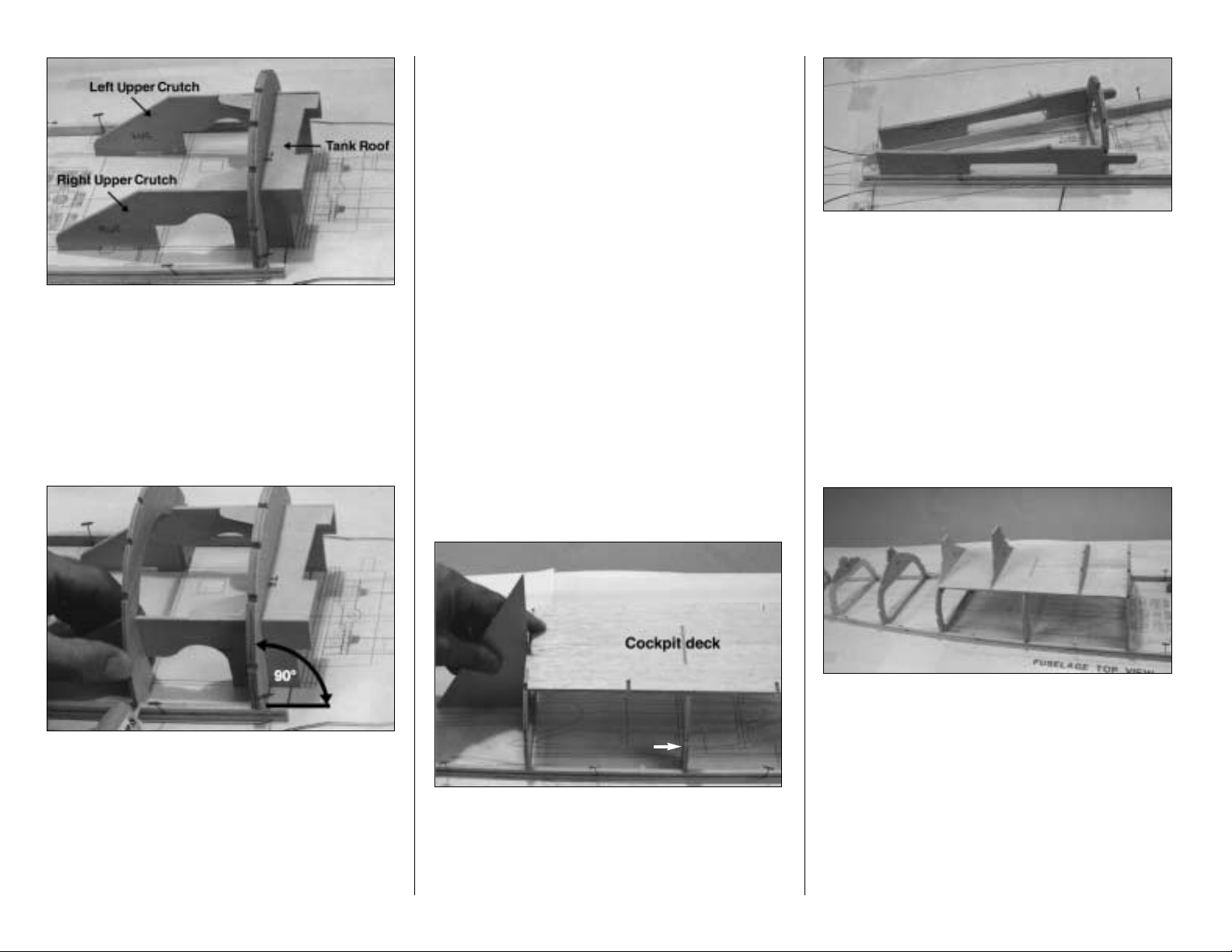
❏ 6. Fit, but do not glue, the Tank Roof (TR)
followed by the Right Upper Crutch (RUC) and
Left Upper Crutch (LUC) into former F-1. Place
the assembly in its location on the plans between
the main stringers. Note: Left crutch is slightly
longer than the right crutch to set the engine
thrust angle.
❏ 7. Fit former F-2 to the upper crutches. Making
sure F-1 is perpendicular to the building board, use
medium CA to glue the TR, RUC and LUC to the
aft side only of F-1. Later we’ll glue the parts to
the front of F-1 with a fillet of epoxy. Do not glue
the TR to the upper crutches forward of F-1.
Glue F-1 and F-2 to the side stringer and glue F-2
to the crutches.
NOTE: From this point on you will encounter a few
areas on the structure that may be difficult to glue
because they are not easily accessible. At this
early stage much of the structure only needs to be
tack glued, but it can be reinforced with thick or
medium CA after the sheeting is applied and the
frame is removed from the building board.
❏ 8. Drill 3/16" holes through the punch marks in
formers F-7 and F-8. With the numbers facing
forward, glue the remaining formers F-3 through
F-9 to the side stringers.
NOTE: Use a small triangle to hold ALL
formers vertical while gluing. Any small warps
or twists will be taken out when the 3/16"
stringers are glued in later.
❏ 9. Glue the two halves of the die-cut 1/8" balsa
Cockpit Deck together, then glue it to formers F-3,
F-4 and F-5. NOTE: If you will be installing the Top
Flite Scale Cockpit Interior, do not glue the cockpit
deck to F-4.
❏ 10. Glue the die-cut 1/8" plywood Stab Saddles
to F-9 and the side stringers. Note: The bottom
edges of the stab saddles are not flush with the
side stringer but set away from the outside edge
slightly. Also, the tops of the saddles are canted
toward each other.
RAZORBACK VERSION:
Perform steps 11, 12 and 13 only if building the
Razorback version.
❏ 11. Glue the die-cut 1/8" plywood formers IP, CB
and 5-C to the cockpit deck and former tops 6-C
and 7-C to their respective formers. Hint: If you
have decided to install the Top Flite Scale Cockpit
Interior, glue the IP to the cockpit deck from the
front only and CB from the back only. Most of the
cockpit deck will be cut flush with IP and CB.
NOTE: Save all the unused portions of the
3/16" x 3/16" stringers used during
construction of the fuselage.
- 16 -
F-4
Page 17
❏ 12. Use a drafting triangle to hold the formers
vertical and remove any twists as you glue one
3/16" x 3/16" x 42" balsa stringer in F-1 through
F-9 on each side of the fuselage. Cut the stringers
flush with F-1. Glue 3/16" x 3/16" x 24" stringers in
the rest of the formers on the aft end of the
fuselage. The middle stringer on each side extends
past F-9 1-1/2" and will be trimmed to exact size
later. The top 3/16" stringers end at the forward
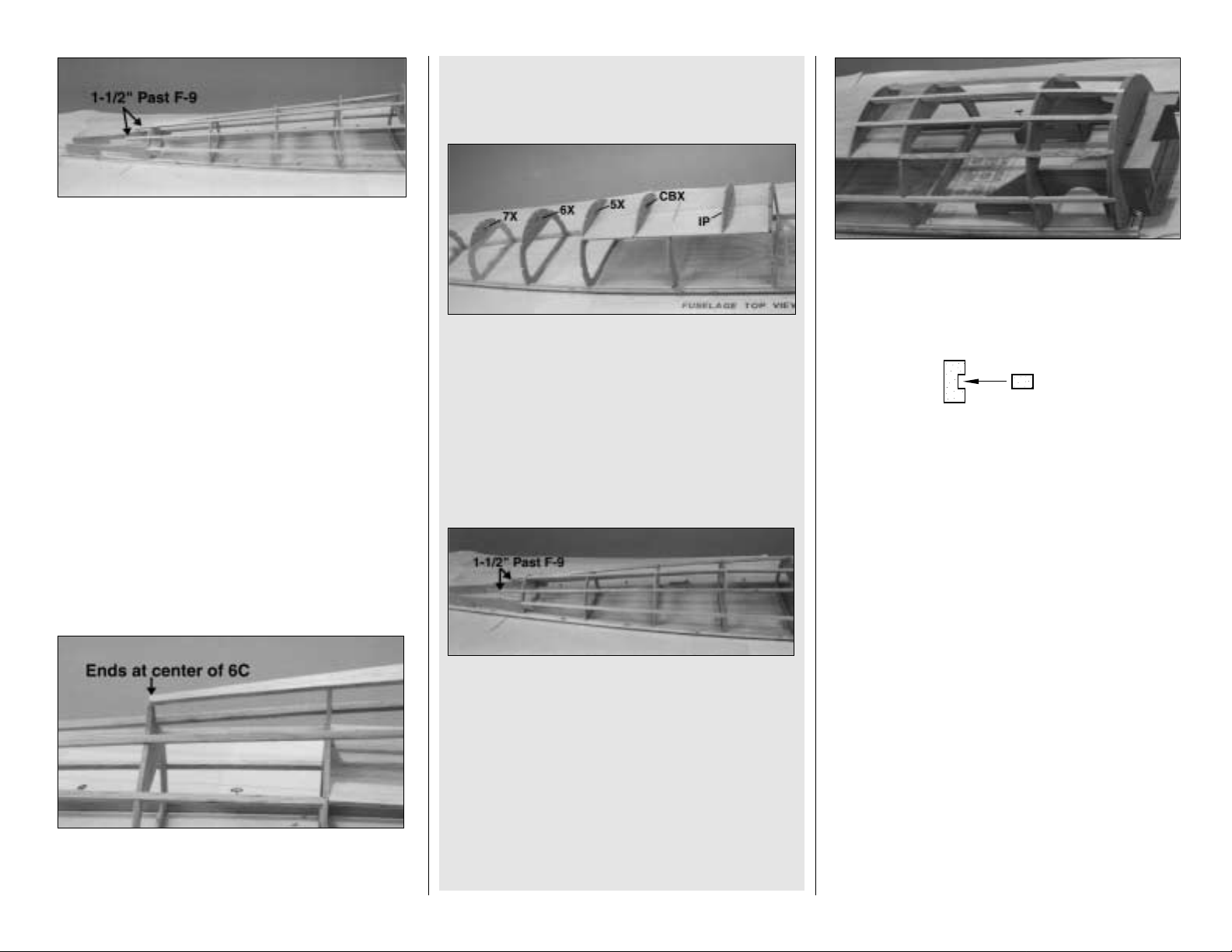
surface of F-9. NOTE: Do not glue the top stringers
to F-9.
❏ 1
3. Glue the die-cut 1/8" balsa Razor Spine to
the top of CB, 5-C and 6-C. NOTE: The aft edge of
the razor spine ends at the center of 6-C.
❏ 16. Cut and glue the rest of the stringers for the
front of the fuselage from three 3/16" x 3/16" x 24"
balsa sticks.
❏ 17. Use thin CA (wiping away any excess before
it cures) to glue two 1/8" x 3/16" x 24" balsa substringers into the groove in each side main
stringer. These sub-stringers will provide a ledge
for the sheeting.
❏ 18. Lightly sand all joints and blend the stringers
to the formers in preparation for sheeting. Use a
razor plane to bevel the edges of the cockpit deck.
SHEET THE SIDES OF THE FUSELAGE TOP
❏ 1. Locate the two shaped 3/32" balsa Main
Upper Fuselage Side Sheets. The fuselage is
longer than the sheet so we’ll add a piece to the
rear later. Refer to the plans for the position of the
side sheet.
BUBBLE CANOPY VERSION:
Perform steps 14 and 15 if building the Bubble
Canopy version.
❏ 14. Glue the die-cut 1/8" Plywood Formers IP,
CBX and 5X to the cockpit floor and former tops
6X and 7X to their respective formers. Hint: if
you have decided to install the Top Flite scale
cockpit, glue the IP to the cockpit deck from the
front only and CBX from the back only. Most of
the cockpit deck will be cut flush with IP and CB.
NOTE: Save all the unused portions of the
3/16" x 3/16" stringers used during
construction of the fuselage.
❏
15. Use a drafting triangle to hold the formers
vertical and remove any twists as you glue one
3/16" x 3/16" x 42" balsa stringers in formers F-1
through F-9 on each side of the fuselage. Cut
them flush with F-1. Glue 3/16" x 3/16" x 24"
stringers in the rest of the formers on the aft end
of the fuselage except for the top, middle
stringer. Notice the middle stringer on each side
of F-9 extends 1-1/2" and will be trimmed to exact
size later. The top 3/16" stringers end at the
forward surface of F-9. NOTE: Do not glue the
top stringers to F-9.
- 17 -
MAIN
MAIN
SUB-STRINGERSTRINGER
Page 18

❏ 2. Wet the outside surface of a sheet and test fit
it to the fuselage. Hint: a 50:50 mixture of water
and rubbing alcohol applied to the outside surface
will make the sheeting easier to bend. Make
adjustments to the sheet if required.
❏ 3. Apply a bead of thick CA (remember the CA
may cure on contact if there is any residual
accelerator in the balsa wood) to the main side
stringer and sub stringer then quickly place the
sheet in position. Start from the middle and work
outward inserting T-pins to hold the sheeting in
place until the CA cures.
❏ 4. Glue the top of the side sheet to the stringers
and cockpit deck with thin CA starting from the
middle and working outward. Glue the sheet to the
rest of the stringers and formers.
❏ 5. Glue the other sheet to the fuselage in the
same manner. Add a piece of leftover 3/32"
sheeting to the rear of each fuselage side.
GLUE THE STABILIZER AND FIN TO
THE FUSELAGE
❏ 1. Carefully trim the fuselage side sheeting until
it is even with the plywood inner stab saddle. Make
adjustments to the fuse sides very carefully so you
don’t change the incidence angle set by the
inner stab saddle. If sanding is necessary, put
masking tape over the inner stab saddles. Trial fit
the stab to the saddle. Continue trimming the balsa
side sheeting and the stringers that extend past
F-9 until the stab contacts the entire length of the
plywood stab saddle.
❏ 2. Remove the stab and trial fit the fin to the
fuselage. A small piece of fin sheeting will need
removed from the fin LE so it will fit in former
F-9. The fin is in the correct position when the front
of the fin trailing edge contacts the plywood stab
saddle, the bottom of the fin trailing edge contacts
the work surface and the fin LE fits all the way
down into F-9. Study the fuselage side view. The
trailing edge of the fin must be perpendicular to the
work surface.
❏ 3. Place the stab onto the stab saddle, then trim
the sheeting on both sides of the fin until it fits in
the same position it was when you fit it without
the stab.
In preparation for gluing the stab and fin to the
fuselage, make a “dry run” of the next few
steps first without using any glue so you
understand the procedure.
❏ 4. Put the stab on the saddle and add weights to
hold it in place. Measure the height of each tip
above the work surface and if not identical, make
small adjustments to the saddle and fuse sides.
Hint: Slide 1-3/8" balsa blocks (not supplied) under
the tips and adjust their position to level
the stab.
- 18 -
Page 19

❏ 5. Use a string, pinned to the center of the top
stringer at F-1, to equalize the distance of the stab
tips to the nose. Hint: An alternate method to the
“string and pin” technique, is to extend the line on
the plans showing the trailing edge of the stab,
then align the stab with this line. Use a pen and a
straightedge to draw the line.
❏ 6. Accurately draw a centerline along the length
of the fin post (or use the same centerline
previously drawn for hinging). Fit the fin into the
stab and fuselage, then clamp the rear of the
fuselage sides together. Use a triangle to confirm
that the fin is perpendicular to the work surface.
When it’s time to glue the fin to the fuse and stab,
masking tape may be used to hold the fin in
position while the epoxy cures.
❏
7. Double check all alignments. Permanently glue
the fin and stab in position with 30-minute epoxy.
COMPLETE THE FUSE TOP
RAZORBACK VERSION:
Perform steps 8 through 13 only if you are building
the Razorback version.
However, if you are installing the optional cockpit
kit (no matter which version you are building), skip
ahead and perform steps 3 & 4 on page 21 before
you glue the top fuse sheeting in position.
❏ 8. Trim the shaped 15" balsa Fuselage Spine
to fit between the leading edge of the fin and the aft
edge of the Razor Spine then glue it to the formers.
Bevel the sides of the Razor Spine so it blends with
the curvature of the formers. (See cross section on
fuselage plan.)
❏ 9. Use the template on the plans to make a
Right and a Left Aft Fuselage Top from two
3/32" x 3" x 30" balsa sheets. Start by fitting the
bottom edge of one of the top sheets to the side
sheet, on the fuselage. Position the top sheet on
the fuselage and mark where it will be notched for
the Razor Spine.
❏ 10.
Cut the notch in the top of the sheet so it will
fit against the Razor Spine and fuselage spine. Wet
the inside portion of the sheet that bends inward
towards the fuselage and wet the outside of the
portion of the sheet that bends around the formers.
Hint: The best way to make the sheeting conform to
the compound curves of the Razorback is to liberally
wet the sheet then place it on the fuselage and little
by little bend it into position. Wet, then reposition the
sheet on the fuselage a few times continuously
bending it to shape each time. Let the sheet dry for a
few minutes before permanently gluing it. Glue the
aft top sheet to the fuselage.
❏ 11. Trim the top edge of the sheet where it
meets the Razor Spine and fuselage spine. Glue
the other aft top sheet to the fuselage in the same
manner as the first.
❏ 12. Position the 1/2" x 1-1/4" x 8" Aft Deck Top
Block on the Razor Spine and trace its outline.
Carve the top block to approximate shape, then
glue it in position.
❏ 13. Glue a 1-1/4" wide strip of 3/32" balsa to the
cockpit sides joining the front deck. Refer to the
cross section and side view on the plans then use
a razor plane and a sanding block to blend the aft
deck top block to the fuselage. Cut out the canopy
and use it as a guide to accurately shape the
top block.
- 19 -
Page 20

❏ 14. Cut the Upper Forward Fuselage Tops
from a 3/32" x 4" x 30" balsa sheet. This should be
done in two halves with the pieces joining in the
center of the top middle stringer.
❏ 15. Wet the outside of an upper forward fuselage
top to soften it, then place it on the upper forward
frame. It should overlap the instrument panel and
F-1 by about 1/8".
❏ 16. Glue the top to the fuselage. Cut the other
side of the upper forward fuselage top to fit on the
fuselage then glue it in position the same as you
did the first piece.
FINAL FIT THE CANOPY
RAZORBACK VERSION
❏ 1. Use leftover balsa and the templates on the
plans to make the 1/16" Razorback Cockpit
Fairings and the 1/8" Cockpit Fairing Formers.
❏ 2. Set the canopy on the fuselage and mark the
location of the cockpit fairing formers. Glue the
formers to the fuselage.
❏ 3. Replace the canopy on the fuselage to
confirm the position of the cockpit formers and test
fit the cockpit fairings. Make adjustments if
necessary, then glue the cockpit fairings in place.
❏ 4. Apply HobbyLite balsa filler around the
fairings to blend them to the fuselage sheeting.
Apply a couple of thin layers and sand between
each application.
FINAL FIT THE CANOPY
BUBBLE CANOPY
❏ 1. Cut the bubble canopy to the trim lines
scribed around its perimeter. Lightly sand the
butyrate to smooth the edges.
❏ 2. Fit and glue two pieces of leftover 3/32" balsa
sheet between IP and the cockpit’s aft former.
These pieces should extend about 1" above the
upper stringer as shown.
❏ 3. Refer to the plans for the canopy location,
then position the canopy on the fuselage. Trace
around the canopy to define its shape around the
cockpit. Remove the canopy. Draw a second line
parallel to and 1/4" above the first. Trim the excess
balsa to match the second line.
COMPLETE THE FUSE TOP
BUBBLE CANOPY VERSION:
Perform steps 8-10 only if building the Bubble
Canopy version.
❏ 8.
Reference the cross section on the plans,
then cut a notch in former F-8 for the top stringer.
Trial fit the 3/16" x 3/16" x 24" stringers in the
notches in the tops of the formers. The aft end will
have to be shaped to fit between the stringers at
former F-9. Glue the stringer in position.
❏ 9. Use the template on the plans to make a
Right and a Left Aft Fuselage Top from two
3/32" x 3" x 30" balsa sheets. Wet the outside of
one of the tops, then glue it to the top edge of
the aft fuselage side and the stringers. Apply
medium CA to the formers and top stringer, then
roll the sheet into contact. Hold it in position until
the CA cures.
❏ 10. Custom fit the other aft fuselage top
then glue it to the other aft fuselage side in the
same manner.
- 20 -
Page 21

FINAL STEPS BEFORE FRAMING
THE LOWER FUSE
❏ 1. Turn the fuselage over and reinforce all glue
joints that don’t look strong or that you couldn’t
reach before. Do not glue the tank roof to the
upper crutches forward of F-1 until told to do
so. Add a fillet of 30-minute epoxy inside the
fuselage where the stab meets the plywood
saddle. Hint:
An inexpensive Robart®Super Stand
works well to support the fuse and because it’s
made of Styrofoam®and can be modified to
conform to the fuse shape.
❏ 2. Use model filler (Hobbico
HobbyLite
balsacolored filler recommended) to begin blending the
top deck with the stab and fin. Apply in thin layers
allowing each layer to dry thoroughly before the
next application.
Perform steps 3 & 4 only if installing the optional
scale interior kit.
❏ 3. If you are going to install the Top Flite Scale
Cockpit, remove the cockpit deck in the cockpit
area. Measure 2-3/16" from both sides of the joint
in the cockpit deck halves along the instrument
panel (IP) and the cockpit back (CBX).
❏ 4. Cut out the cockpit deck close to IP and CB
(CBX for Bubble Canopy) and along the lines
2-3/16" from the center. Sand the cockpit deck
flush with the cockpit back and instrument panel.
The top portion of F-4 will be removed later.
❏ 5. Apply masking tape to the bottom of the Stab
and also the Fuse Side about 3/16" on either side
of the joint. Mix a little 30-minute epoxy, then
squeeze it into the Stab/Fuse joint. Remove the
tape before the epoxy cures and feather the
excess with your finger.
❏ 6. Once the epoxy has cured, apply more
masking tape about 1/4" out from the joint, then
use model filler to create a neat fillet along the
length of the joint. Once again, remove the tape
before the filler dries and feather the edges with
your finger to avoid excessive sanding.
❏ 7. NOTE: Protect the stab and fin skins with
masking tape around where you will be
sanding to avoid the possibility of dangerously
thinning the skins. Lightly sand the first layer of
filler around the Stab and the Top Deck, then
apply a second coat. When the filler is dry use
different thickness dowels wrapped with 220-grit
sandpaper to shape the fillet.
Take your time to
blend all contours with the Fuse.
FRAME THE FUSE BOTTOM
❏ 1. Drill 3/16" holes through the punch marks in
formers 4-B and 5-B.
❏ 2. Test fit the die-cut 1/8" ply Left and Right
Lower Crutches to the formers in the fuselage
then add the die-cut 1/8" formers 2-B, both 3-B’s,
4-B and 5-B without gluing any parts. Make sure
all the formers fit into the notches in the crutches
and make sure the lower formers fit into the upper
formers. Make adjustments if necessary.
❏ 3. Test fit 1-B and TF to the crutch in the
fuselage. Make sure 1-B fits well into former F-1.
Make adjustments if necessary.
❏ 4. After any required adjustments have been
made, use a straightedge to keep each lower
former parallel to each upper former, then glue
them together. Double check that F-1B is
parallel to F-1. Glue the crutches to the lower
formers. Glue the tank floor to the crutches and
formers. NOTE: Do not glue the tank floor to the
crutches forward of F-1B at this time.
- 21 -
Page 22

❏ 5. After carefully aligning the holes, glue both
2-C’s to the forward surface of F-2B. Inspect all the
glue joints and add small fillets of medium CA
where each former meets the crutches.
❏ 6. Glue the remaining lower formers 6-B
through 8-B to their respective upper formers.
Use a straightedge to maintain vertical alignment
between top and bottom formers. Hint: For better
bonding with the sheeting, lightly sand the formers
edges so that they are slightly beveled to match
the angle of the fuse toward the tail.
❏ 7. Drill a 5/64" hole through the two
forward punch marks in the die-cut 1/8" plywood
Tail-wheel Deck (TW) and a 9/64" hole through
the aft punch mark. Insert 9-B into TW and glue
them to the fuselage as shown on the plans. Glue
5-D to the crutches.
❏ 8. Glue three 3/16" x 3/16" x 24" stringers in the
aft former notches; one in the bottom and one more
in each middle notch as shown in the photo.
NOTE: The two side stringers at former F-9 do not
end at the aft edge of F-9 but are inset 1/16". Use a
straightedge as you glue in the stringers to keep
the formers in vertical alignment.
❏ 9. Test fit the die-cut 3/32" balsa Wing Saddles
to the formers, then glue them in position.
TAIL GEAR INSTALLATION
❏ 1. Cut the Aft Post flush with the nylon Tail
Wheel Bracket.
❏ 2. Use a pliers to flatten 1/4" of one end of the
1/8" x 5/8" Brass Tube. Slide the tube on the Tail
Wire and check the parts over the fuselage top
view to make sure they match up well. Use silver
solder to solder the brass tube to the top of the
tailwheel wire.
❏ 3.
Mark the location of the Metal Ball on the end
of the brass tube and drill a 1/16" hole at the mark.
❏ 4. Attach the ball permanently to the tail gear
with the Small Nut provided. Put a drop of epoxy
on the threads to prevent it from coming loose.
❏ 5. Use the 4-40 Set Screw to lock the Collar at
the height shown on the fuselage side view, but
orient the set screw so small adjustments can be
made later during construction if required.
❏ 6. Roughen the tubular Nylon Bearing on the
tailwheel wire with coarse sandpaper.
SILVER SOLDERING
Use this process when soldering metal to metal, such
as brass tube to wire, or pushrod ends to wire.
A. Thoroughly clean the items to be soldered with
alcohol or degreasing solvent. Pay special attention to
the inside of the threaded brass couplers.
B. Roughen the area to be soldered with fine
sandpaper, then clean again.
C. Assemble the items to be soldered.
D. Apply a small amount of soldering flux. Acid based
liquid flux works best when one or more of the items
is steel.
E. Heat the metal with a soldering gun or iron and
apply solder to the metal. The metal must get hot
enough to melt the solder and the solder must flow
freely into the joint.
F. Do not move the parts until the solder has cooled.
G. Test the joint by pulling hard.
H. Clean off the excess flux with alcohol or solvent.
Coat the parts with a very fine film of oil.
- 22 -
Page 23

❏ 7. Cut two 3" long sticks from one of the
approximately 6" long scrap pieces of 3/16" x
3/16" stringers leftover from the top of the
fuselage. Bevel one end of each stick, then glue
one of them to the side of middle stringer on the
very bottom of the fuselage. The other one will be
glued on at step 11.
❏ 8. Place the tailwheel assembly on the tailwheel
brace with the nylon bearing tube next to the
stringer. Mark the location with a pen then cut a
notch in the stringer for the nylon bearing.
❏ 9. Test fit the tailwheel assembly with the
bearing in the notch. Rotate the tailwheel wire and
check for binding. Make adjustments if necessary.
❏ 10. Put a few drops of 30-minute epoxy in the
holes of the plywood tailwheel brace and the bolt
holes of the nylon bracket. Screw the nylon
bracket to the brace with two #4 x 3/8" Sheet
Metal Screws.
❏ 11. Force some epoxy into the notch of the
stringer and around the nylon bearing being
careful not to get any epoxy inside the tube. Glue
the remaining 3/16" x 3/16" x 3" stick to the other
side of the stringer to lock the nylon bearing
into position.
❏ 12. Cut the .074" x 36" Threaded One End Rod
to approximate length by removing 7" from the
non-threaded end. Thread a Dual-Ended Ball
Link 14 full turns onto the threaded end.
❏ 13. From the 6-1/2" long piece of inner pushrod
tube, cut 11 pieces approximately 3/8" in length
and slide four of them onto the rudder pushrod,
spaced as shown on the plans.
❏ 14. Mark and cut the rudder and elevator
pushrod exits where shown on the fuselage plans.
Bevel the exits with a sharp knife or a round file to
allow the outer pushrod tubes to exit at the angle
shown on the plans.
❏ 15. Place two 36" long grey Outer Pushrod
Tubes over the Elevator Pushrod Tube and
Forward
Rudder Pushrod Tube drawings on the
top view of the fuselage plans. Cut them a few
inches longer than length shown. Use 220-grit
sandpaper to roughen the outside of the tubes so
glue will stick to them.
❏ 16. From one of the short cut-off pieces of 36"
pushrod tube, cut a 5" long piece for the Aft
Rudder Pushrod Tube and sand the outside.
❏ 17. Slide the forward rudder pushrod tube and
the elevator tube through the holes in the formers
and position them as shown on the plans with the
excess length forward of F-4 Note: Remember
you are looking at the top view of the plans.
Position the pushrods on opposite sides of the
fuse, when looking at the fuse from the bottom.
❏ 18. If you haven’t already done so, cut the
rudder hinge slots. Temporarily install the rudder
onto the fin.
❏ 19. Install the Forward Rudder Pushrod
through the slot in the rear of the fuselage. Position
the dual-end ball link on the ball but do not snap
it on yet.
❏ 20. Thread a Nylon Clevis onto the .074" x 12"
pushrod then place it over the Aft Rudder Pushrod
drawn on the plans and cut it 1/8" longer than shown.
❏ 21. Temporarily snap a Small Control Horn
onto the clevis and slide a Threaded Coupler on
the end of the rod. Slide the control rod through the
pushrod exit in the aft end of the fuselage and
place the control horn on the rudder in the position
shown on the plans.
❏ 22. Observe the location of the threaded
coupler and see if the length of the pushrod is
correct. With the rudder and tailwheel in neutral
position the threaded rod should be able to
screw into the dual-end ball link about 3/16".
Make adjustments to the length of the pushrod if
required.
❏ 23. Once the threaded coupler is soldered to
the pushrod and the system is hooked up and
closed in, some adjustment may be made by
screwing or unscrewing the clevis but the more
accurate it is now, the less adjustment you may
have to make later. Slide one of the 3/8" spacers
onto the aft rudder pushrod, then use silver solder
to solder the threaded coupler onto the pushrod.
- 23 -
Page 24

❏ 24. Bevel the aft rudder pushrod tube so it
matches the angle of the fuselage. Install but don’t
glue the tube in the pushrod exit, then cut the
forward end so it extends 1/8" past the slot in the
plywood stab saddle.
❏ 25. Slide the aft rudder pushrod through the aft
pushrod tube temporarily mounted in the fuselage.
Confirm that the alignment and location of the
pushrod and tube is correct. Make adjustments if
necessary, then permanantly glue the aft pushrod
tube to the fuselage.
❏ 26. Prior to permanently connecting the aft
rudder pushrod, fill any gaps where the pushrod
tube exits the fuselage with some Micro Balloons
(Top Flite recommended) and epoxy. After it cures,
final sand to make a smooth, clean pushrod
tube exit.
❏ 27. Permanantly install the aft rudder pushrod.
Hold the dual-end ball link with a pliers and screw
in the aft pushrod. Check the length of the rod, and
how far it is screwed into the dual-end ball link.
Make adjustments if required. Snap the ball link
onto the ball.
❏
3. Hold an air exit up to the side stringer, then
use a ball-point pen to mark where the side
stringer interferes with it. Use a razor saw to
carefully cut through the side stringer and
sheeting. Remove this piece from the fuselage.
Perform this step on the other side of the fuselage
.
❏ 4. Glue a 1-1/2" long strip of 1/16" sheet to one
end of the 1/8" x 3/8" x 4-1/4" plywood strip and a
2" long piece to the other end. Make two of these
assemblies.
❏ 5. Glue the main side stringer Braces to the
inside of the main side stringers. Refer to the top
and side view of the fuselage plans for location.
❏ 6. Glue the remaining four 3/16" x 3/16" x 24"
aft fuselage stringers to the notches in
the formers.
FIT THE INTERCOOLER
AIR EXITS
NOTE: If you have decided to install the
supplied vacuum formed intercooler air exits,
follow the instructions below. If you elect not
to install the exits or wish to represent them
in a closed position, follow only step 6 and 7
below. Then, the closed air exits would
simply be represented by panel lines on your
finished model.
❏ 1. Cut out the right and left vacuum formed
intercooler air exits along the cut lines.
❏ 2. The main side stringers between F-6 and
F-7 need to be inset to clear the intercooler air
exits before adding the bottom sheeting. Mark
the location of the air exits on the fuselage side
stringers where shown on the plans.
- 24 -
Page 25

SHEET THE FUSE BOTTOM
❏ 1. If you haven’t already done so, glue the
remaining four 3/16" x 3/16" x 24" aft fuselage
stringers to the notches in the formers.
❏ 2. Use a 3/16" x 3/16" x 24" stringer to make the
two aft stringers from F-9 to the rear of the fuselage.
❏ 3. Use a sanding block and 150-grit sandpaper
to blend the stringers to the formers and eliminate
any glue blobs or irregularities. Even up the
stringer ends with the formers.
❏ 4. Cut two Lower Fuselage Sheets from 3/32"
x 3-1/4" x 42" balsa to match the pattern on the
plan. The cut sheets will be slightly oversize to
allow for final fitting and sanding.
❏❏5.
Test fit the sheet to the fuselage and make
adjustments by carefully shaving away wood where
needed. Trim the sheeting between F-9 and F-5D to
fall on the centerline of the 3/16" Stringer. Aft of F-9
the sheeting is even with the bottom edge (top if
fuselage is upside down) of the stringer.
❏❏6. Position the side sheet on the Main
Stringer
ledge
. Press the sheet against the Main
Stringer and wick thin CA into the joint, from the
inside. Start at the center and work forward and
aft, tack gluing the sheet in place as you proceed.
When the length of the sheet has been tacked in
place, go back and wick thin CA along the entire
inside edge.
❏❏7. Bend the sheet into contact with the aft
stringer then wick thin CA into the joint–from the
center outward. If the balsa sheet is too rigid, use
water on a paper towel to moisten it. Finish
attaching the sheet by wicking CA into all former
and stringer joints along the sheet. Wipe any
excess CA from exposed edges before it cures.
❏❏8. Add a piece of scrap 3/32" balsa to the aft
end of the sheet.
❏ 9. Repeat steps 3-6 for the opposite side.
❏ 10. Use two 3/32" x 4" x 30" balsa sheets to
cover one side of the aft bottom of the fuselage .
Wet the outside of the first sheet to help it bend
around the formers. When satisfied with the fit,
glue it in place with medium CA. Sheet both sides.
Wick thin CA along the top joint.
❏ 7. The stringer below the main side stringer
(above, if the model is upside-down on your
cradle) also must be spliced in order to clear the
intercoolers. Cut a section out of the stringers
directly above the main stringer.
❏ 8. Cut leftover 3/16" x 3/16" stringers to
reinforce the stringers you notched to clear the
intercooler air exits.
- 25 -
Page 26

❏ 11. Trim the ends of the aft bottom sheeting
even with F-9 and F-5D.
❏ 12. Use a sanding block to sand the aft fuse
sheeting flush with the stringers so it tapers to the
bottom edge of the fin post.
❏ 13. Bevel the front edge of the 1" x 2-1/2" x 7"
Aft Fuse Block to fit flush against 9-B. Sand the
aft edge flush with the fin post.
❏ 14. Put the block on the fuselage and trace
around the underside and forward edge to form a
rough cutting outline. Tape the rudder in position
so that you can trace the outline on the aft edge of
the block.
❏ 15. Remove the block, then use a hobby knife
and a razor plane to carve the shape to match the
outline you traced. Glue it in position when
satisfied with the shape.
❏ 16. Continue shaping the aft fuse block to blend
with the fuse. Temporarily install the rudder, then
shape the aft fuse block and the rudder to blend
smoothly with the fuse.
❏ 17. Use 30-minute epoxy to glue the 1/2" x 7/8"
x 1-1/4" Maple Wing Bolt Blocks in the fuselage
at the location shown on the plans.
Note: We will sheet between F-1 and F-2 when
we finish sheeting the belly pan.
INSTALL THE ENGINE
There are a variety of options when it comes to
engine selection. Our prototype P-47 weighed
approximately 10 lbs and flew extremely well with
the Super Tigre .75 2-stroke. When using a 1.20
4-stroke engine, due to the large amount of power
available the P-47 will have a tendency to climb as
full power is applied. This condition can be
controlled by adding an additional one degree of
down thrust to the engine.
NOTE: The following sequence shows the
installation of a Super Tigre .75 engine with the
cylinder mounted at a 45 degree angle towards
the bottom of the fuse. This orientation allows the
exhaust port of a 2-stroke engine to be connected
to a Top Flite In-Cowl Muffler and the engine
exhaust to exit near the bottom of the fuse.
❏ 1. Drill four 7/32" holes through the laminated
Firewall for the engine mounting bolts at the
marked locations. Insert four 8-32 Blind Nuts into
the holes from the aft side and seat them with
gentle taps from a hammer. Wick thin CA around
the flange of each nut to secure it in position.
Avoid getting CA into the threads.
❏ 2. Remove the spacer bar from the back of both
Engine Mount Halves and trim off any burrs.
Temporarily bolt the engine mount to the firewall
with four 8-32 x 1-1/4" Socket Head Cap Screws
with #8 Lock Washers and #8 Flat Washers.
Place the engine between the rails, adjusting the
width of the rails accordingly.
- 26 -
Page 27

❏ 3. Position the engine so the Drive Washer is
6-1/4" (159mm) from the aft edge of the engine
mount. Mark, drill (#29 drill bit) and tap the engine
mounting holes to accept the 8-32 x 1" Socket
Head Cap Screws included with this kit.
❏ 4. Test fit the engine to the mount with the 8-32
screws. Remove the mount from the firewall, then
test fit the firewall to the fuselage as shown in the
plans. Make adjustments to the notches in the
firewall if necessary.
❏ 5. If you are using a Great Planes 14 oz. fuel
tank, drill the holes in the firewall for the fuel lines
now. Drill a 7/32" hole in the center of the firewall
1-7/8" up from the bottom and another 7/32" hole
1" above the first.
❏ 6. Make sure the back surface of the firewall
fully contacts the crutches, tank roof and tank
floor. Use 30-minute epoxy and C-clamps to glue
the firewall in position.
❏ 7. After the epoxy cures, remove the C-clamps
and apply a fillet of 30-minute epoxy on both
sides of F-1 all the way around the tank roof and
tank floor and the right and left crutches. Make
sure the crutches are glued to the tank roof and
floors as well.
INSTALL SERVO TRAY
❏ 1. Test fit your servos in the die-cut 1/8" plywood
Servo Tray and make sure the spacing is correct.
Make adjustments if required. Cut two 1/4" x 4-1/4"
strips from leftover 1/8" lite plywood. These strips
should be positioned on servo tray so that the
servo screws will screw through the center of them.
Glue the strips to the servo tray.
❏ 2. Glue the servo tray to the crutches and former
F-3 with the 1/4" strips on the underside of the
servo tray.
Regroup, clean off the workbench and grab the
wing plans!
FUSELAGE CONSTRUCTION NOTES:
- 27 -
Page 28

BUILD THE WING
NOTE: The wing panels are built “UPSIDEDOWN” on the plans. The jig tabs are attached
to what is, in the end, the TOP surface of the
wing. Since it is the standard convention to
show the Top View of the wing, and the wing
panels are built upside down, the LEFT wing
panel is built over the RIGHT Wing Top View
and vice-versa. This does not present any
problems; just be sure to build a left and a
right wing.
PREPARATION
❏ 1. Locate the four 1/4" x 3/8" x 36" hard balsa
Wing Spars, then cut them 1/4" longer than shown
on the plans. Save the cut-off ends for the flap
servo hatch mounts.
❏ 2. Sand a taper on one end of each of the four
1/8" x 3/8" x 18" balsa Spar Doublers as shown in
the sketch. Laminate a spar doubler to each spar
with the root end of the doubler aligned with the
root end of the spar.
❏ 3. Before removing the 1/16" plywood Dihedral
Braces from the die-cut sheet, draw a centerline
on both pieces by connecting the punch marks.
❏ 4. Remove all the die-cut 3/32" balsa Wing Ribs
and 1/16" ply (or 1/8" ply if installing fixed landing
gear) Rib Doublers. Smooth out any imperfections
with sandpaper. Be sure to keep the jig tabs
attached to the ribs.
❏ 5. Ribs W-2 through W-6 have punch marks just
aft of the spar. Drill a 3/16" hole at each of these
marks for future installation of the aileron pushrods.
❏ 6. Use a straightedge to draw a line on either
side of both W-2 ribs 1/16" behind the spar notch.
Put marks on the line equal to the depth of the
deepest part of the forward notches.
❏ 7. Drill 1/8" holes through the punch marks in the
two die-cut 1/8" plywood Aileron Bellcrank Plates
(AB). Assemble the bellcrank parts as shown in the
sketch (don’t worry, there is no
right
and
left
– you
can’t build them backwards). Put a drop of
6-minute epoxy on the 4-40 nut and threads to
prevent the bellcrank from vibrating loose.
NOTE: If you haven’t already done so, now is
the time to decide if you are going to use
retractable or fixed landing gear.
Skip this step if installing retracts
❏ 8. Locate wing ribs W-4, W-5, W-6 and plywood
doublers W4-F, W5-F and W6-F. Use thick CA to
glue the ribs and doublers together. Be sure to
make a LEFT and a RIGHT of each rib assembly.
Remove the shaded area with a hobby knife or
razor saw.
- 28 -
RETRACT MODIFICATION FOR
CENTURY JET RETRACTS
The standard retract rail spacing in this kit is
designed to accept Robart #606 85 degree
retracts without modification. However, if you
elect to install the Century Jet Model’s retracts,
modify the rails and rib doublers to accept the
CJM retracts as follows. It will be easiest to do
this before framing the wing while the ribs and
doublers are easy to modify.
❏ 1. Use the sketch on page 55 to modify the
1/16" plywood rib doublers before laminating
them to ribs W-5 and W-6.
❏ 2. Make four new retract rails from 1/4" thick
5-ply aircraft plywood. The new dimensions
should be 1/4" x 17/32" x 3-1/16".
2"
SPAR DOUBLER
OUTER SPAR
Page 29

Skip this step if installing fixed gear
❏ 9. Locate wing ribs W-5 and W-6, and 1/16"
plywood doublers 5-R and 6-R (4 each). Use
thick CA to glue the ribs and doublers together.
Remove the shaded area with a hobby knife or
razor saw.
Okay, the prep work is behind you, so now that the
dull stuff is done, let’s build the outer wing panels
so you’ll have something to show when your
friends drop in to check on your progress!
BUILD THE WING PANELS
❏❏1. Place a Wing Panel plan on a flat building
board and cover it with waxed paper.
Cutting the
wing panel sections apart makes handling easier.
❏❏2. Pin a Top Spar to the building board at four
or five locations using the cross-pinning technique
shown in the sketch. The extra length should
extend past the root end of the plan.
❏❏3. Position the die-cut 3/32" balsa ribs W-2
through W-11 on the spar, aligned over their
appropriate locations on the plans. Push rib W-2
forward against the spar. Make sure each rib is
vertical and the jig tabs are contacting the
building board, then glue W-2 through W-11 to
the spar.
❏❏4. Test fit the die-cut 1/8" balsa Aft Inner
Spar in the notches of ribs W-2 through W-7. The
aft edge of the inner spar will be slightly higher
than the ribs to allow for trimming later. Sight down
the trailing edges of the ribs to make sure they are
aligned. Use paper shims under the jig tabs to
raise any ribs that are low. Glue the aft inner spar
to the ribs making sure all the jig tabs are
contacting the work surface.
❏❏5. Trim the end of the aft inner spar flush with
W-7. Bevel the notches in ribs W-7 through W-11
and the notches in the die-cut 1/8" balsa Aft Outer
Spar to account for the forward sweep of the spar.
Test fit but do not glue the aft outer spar in ribs
W-7 through W-11. Fit but do not glue the die-cut
3/32" balsa Aileron Root Rib W-7B. Make sure
the ribs remain aligned over the plans when the aft
outer spar is in position.
❏❏6. Sight down the trailing edge of the ribs and
make sure they are aligned. Use paper shims to
raise any low ribs if required. Slip three layers of
waxed paper between W-7B and W-7 up to the
front edge of the aft outer spar then glue W-7B to
W-7. Glue the aft outer spar to the ribs making
sure all the jig tabs are contacting the
work surface.
❏❏7. Fit but do not glue the die-cut 1/8" plywood
Dowel Plate (AFT) into rib W-2 then add rib W-1 to
the assembly. Still without using any glue, press
the Bottom Main Spar into the notches and check
for a flush fit at each rib. Confirm that the spar
extends past the dowel plate and rib W-11. Glue
the bottom spar to all ribs except W-1.
❏❏
8. Draw a line connecting the two punch marks
on the die-cut 1/8" plywood Dihedral Gauge.
❏❏9. Use the dihedral gauge and the dowel
plate to set the angle and position of W-1 (see
the photo at step 10). The line on the dihedral
gauge must line up with the offset reference line
on the plans.
The location of the rib drawn on the
plans indicates the centerline of the rib – not
where the top of the rib contacts the plans.
Because of this, the top of the will be slightly offset
to the right (or left for the other wing panel).
- 29 -
Page 30

❏❏10. Hold the dihedral gauge near the middle
of W-1 and lightly tack glue the rib to the top and
bottom main spars. Do not glue the dowel plate
until told to do so.
❏❏11. Move the dihedral gauge near the trailing
edge of the rib, then using the same technique, set
the angle and position of W-1. Glue the rib to the
aft outer spar.
❏❏12. Use a spacer (such as one of the dihedral
braces or a flap hatch cover) to position the dowel
plate 1/16" in front of the main spars. Glue the
dowel plate to ribs W-1 and W-2.
❏❏13. Glue a die-cut 1/8" plywood Dowel Plate
(FWD) in the notches of ribs W-1 and W-2.
❏❏14. Cut the shaped balsa Leading Edge to
the correct length as shown on the plans and
carefully bevel the ends. Center the leading edge
vertically on the front edge of the ribs, then glue it
to ribs W-2 through W-11.
❏❏15. Skip this step if you are NOT going to
build the optional flaps.
Please consider this
strongly – the flaps are not at all difficult to build
and they really add to the flight realism and make
landings lots of fun.
Place the die-cut 3/32" balsa
Flap Root Rib W-2F next to W-2 as shown on
the plans. Slip three layers of waxed paper
between W-2 and W-2F up to the “V” notch then
glue W-2F to W-2 forward of the V notch.
❏❏16. Trial fit the tapered 18" Flap Spar into the
“V” notches just behind the aft inner spar and cut it
to fit from W-1 to W-7. Make sure it fits all the way
down into the notches so the upward facing
surface is flush with the ribs. Make adjustments to
the notches if necessary then glue the spar
into position.
❏❏17. Make two Flap Servo Hatch Supports
and two Aileron (or releasable drop tank) Servo
Rails from two of the 1/4" x 3/8" spar cut-offs, then
glue them to the notches in the ribs. If you don’t
plan on using flaps, fill the notches with scrap balsa
(or you could install the rails anyway).
- 30 -
FLAP SPAR
Page 31

❏❏18. With the bellcrank facing away from the
plans, glue the aileron bellcrank plate into the slots
in ribs W-7 and W-8.
❏❏19. Test fit Tip Ribs W-12 and W-13 and the
die-cut 1/8" plywood Tip Spar to the tip of the
wing. Make sure W-13 is vertical and the jig tabs
are contacting the work surface, then glue the
assembly in position.
❏❏20. Locate the 5/8" x 1" x 7" balsa stick and
make the Tip Leading Edge. Bevel each end as
shown on the plans. Glue the tip leading edge
in position.
Proceed to step 25 if you will be installing
retractable landing gear.
❏❏21. Test fit a 1/2" x 3/4" x 6-3/4" grooved
Landing Gear Rail into the notches in ribs W-4,
W-5, and W-6. The fit should be snug and the
groove should be facing away from the work
surface. Be sure that the rail extends past W-4
approximately 3/4" as shown on the plans. Use
30-minute epoxy to glue the rail in position.
❏❏22. Use 30-minute epoxy to glue the 1/2" x
3/4" x 1" maple Landing Gear Block to the top of
the rail and the side of W-4F.
❏❏23. Draw a line 3/16" from W-4F on the
landing gear rail.
❏❏24. Carefully drill a 3/16" hole at this mark in
the middle of the groove all the way through the
maple block with the drill perpendicular to the
rail as shown in the photo.
- 31 -
FOR RETRACT GEAR ONLY
Hot Tip: The key to a durable landing gear
mounting structure is building accuracy and good
glue joints, not lots of epoxy. Please take
your time, plan ahead, and work carefully during
these steps.
❏❏25. Before using any glue or drilling any
holes, test fit the plywood retract rails in
the notches of ribs W-5 and W-6 together with
your retracts.
❏❏26. Remove a section from ribs W-4 and W-3
so you may retract the landing gear, preferably
with the wheel installed, into the wing.
The shape
or size of the pieces of wood you remove does
not matter as long as it provides enough room
to allow the wheel and landing gear to fully
retract
. These scraps will be glued back in place
after this operation.
❏❏27. With the landing gear fully retracted,
confirm that the strut and wheel go into the wing
an acceptable amount. NOTE: With the standard
Robart wire strut installation, the landing gear and
Page 32

❏❏30. Use a sanding block and 150-grit
sandpaper to blend the upward facing surfaces of
the wing ribs and spars.
❏❏31. Use the patterns provided on the plans to
make the Upper and Lower Flap Skins and the
Aileron Skins from four 1/16" x 3" x 36" balsa
sheets. Use the bevel gauge (assembled during
elevator construction) to mark the bevel line and
the rib end line on the inside surfaces of the skins,
then sand the bevel just as you did for the elevator
and rudder skins.Note: Be sure you make a right
and left set.
❏❏32. Draw a line on the inside surface of the
upper flap skin 3/32" from the outboard tip. This will
indicate exactly where to position the skin over W-7
so you do not glue it to W-7B. Glue the upper flap
skin to the ribs. Hint: Refrain from using
accelerator during this step so that the CA you
use to glue on the
bottom
flap skin will not
prematurely cure.
❏❏33. If building flaps, push a pin between W-2B
and W-2 through the Upper Flap Skin about 1/8"
from the end of the ribs. This “point” will be used
later as a reference of where to cut the flap root
away from the wing.
❏❏34. Glue the lower flap skin to the wing
and the trailing edge of the upper flap skin with
thick CA.
❏❏35. Wet the outside surface of the top aileron
skin. Position it on the wing and glue it only to ribs
W-7B - W-10. Cut a piece of scrap balsa so that
when inserted in between the skin and the building
board it raises the skin in alignment with the tip of
the aft outer spar. Insert the shim, then glue the
aileron skin to the rest of the ribs. Leave the shim
in place until the wing is removed from the
building board.
❏❏36. Wet the outside surface of the other
aileron skin and glue it to the upper skin
and ribs.
❏❏37. Custom fit, then glue eight 1/16" balsa
Vertical Grain Shear Webs to the rear of the main
spars between all ribs except W-1 and W-2, and
W-2 and W-3. NOTE: It’s still important to keep the
wing on your flat building board. When you remove
two crossed pins to glue in a shear web, replace
one pin by pushing it through the shear web and
spar into the building board.
❏❏38. Remove the wing from the building board.
Carefully trim off all jig tabs except the jig tabs on
W-1 and W-11. Sand the ends of the spars and the
flap sheeting flush with W-1.
Return to step 1 to build the other wing panel.
Use the other half of the wing plan and
remember to build a right and a left wing panel.
- 32 -
wheels will retract fully into the wheel well. With
the CJM retracts and the modifications to the rib
doublers shown in the sketches, the strut
protrudes outside the wing skin about 1/16" to
1/8". It may be possible to fully enclose the wheel
and strut inside the wheel well by deepening the
notches in the plywood rib doublers W-5R but
this is not recommended as it will weaken the
structure.
❏❏28. Make adjustments to the notches in the
doublers if required, then use 30-minute epoxy to
glue the retract rails in position.
❏❏29. (Optional) Make a Front Retract Rail
Sheer Web from a 2-1/2" wide piece of 5-ply
aircraft plywood (not supplied). Glue it to the
front retract rail and the rib doublers with
30-minute epoxy. NOTE: This front retract rail
sheer web is recommended for solid strut type
retracts or flyers who fly off of rough grass fields
but is optional and not required for coil type
wire struts.
Retract installation will be completed after
the wing panels are joined. This will allow you to
insure that both installations are identical by
comparing the two and making small
adjustments if required.
Page 33

JOIN THE WING PANELS
❏ 1. Cut away the portion of rib W-1 behind the
dowel plate and 1/16" behind the main spars. Cut
away the portion of rib W-2 behind the main spars
on the line you drew earlier. This will allow the
dihedral braces to pass through the ribs. Do this to
both wing panels.
❏ 2. Test fit both die-cut 1/16" plywood Dihedral
Braces into each wing half. Make sure the brace
centerline can go all the way to the wing centerline.
Trim the ends of the brace slightly if required.
❏ 3. Align the holes of the die-cut 1/8" plywood
Wing Bolt Plates (TOP) and (BOTTOM) then glue
them together.
❏ 4. Test fit the wing bolt plate into each wing
panel. Make adjustments if necessary.
IMPORTANT: Check your work surface with a
metal straightedge to make sure that it’s
perfectly flat before proceeding. Make a “dry
run” of step 5 before actually performing it with
glue. Predetermine where you will place clamps
on the dihedral braces and W-1’s.
❏
5. Join the wing halves with the dihedral braces
and the wing bolt plate. Place the wing upside down
on your flat work table. Slide the 1/2" x 2" x 6-1/2"
balsa Wing Dihedral Block under W-1’s and the
1/4" x 1/4" x 7-7/8" balsa Wing Jig Sticks under the
W-11’s at each wing tip. The dihedral block and wing
jig sticks should be positioned so they contact the jig
tabs and the top main spar. The 1/2" side of the
block should be contacting the work surface and the
wing, and the 2" side of the block should be vertical.
❏ 6. When you have confirmed that all parts fit
well, disassemble the pieces. Coat the dihedral
braces where they will contact the spars, the spars
(where they will contact the dihedral braces of
course) and W-1’s with 30-minute epoxy.
Reassemble the wing parts and place the wing on
the dihedral block and wing jig sticks as you did in
the previous step. Make sure the wing is properly
jigged and all parts are in position. Clamp the
dihedral braces to the spars. Clamp the W-1’s
together. Use a cloth to remove excess epoxy
before it cures.
❏ 7. After the epoxy has cured, remove the
clamps. Do not remove the jig tabs from W-11
and W-1 yet. Glue the die-cut 1/8" plywood rib
doublers W-1D and W-2D to ribs W-1 and W-2 as
shown on the plans. Apply a fillet of epoxy around
the wing bolt plate and where both W-1’s meet the
aft plywood dihedral brace.
❏ 8. Glue the last two 1/16" shear webs between
W-2 and W-3 on both sides of the wing.
- 33 -
Page 34

PREPARATIONS BEFORE ADDING
BOTTOM WING SHEETING
❏ 1. Sand the 3/16" x 36" Outer Pushrod Tube so
glue will stick to it. Cut it to the lengths shown on
the plans for the right and left wing panel. Slide the
pushrod tubes through the holes in the ribs and
glue the tubes in position.
If not installing retracts, skip the next three steps.
❏ 2. Test fit both retracts in the wing and confirm
that the struts are at the same angle when
retracted and extended. Make adjustments if
necessary, then drill the retract mounting holes
for the mounting screws recommended by
the manufacturer.
❏ 3. Temporarily mount the retracts to the rails,
then use left over balsa to build a supporting base
for the sheeting, as shown in the photo.
❏ 4. After you have completed the retract
installation in both wing panels, remove the landing
gear. Replace and glue in the scraps of wood you
removed from W-3 and W-4.
SHEET THE BOTTOM OF THE WING
Our suggested wing sheeting process allows
you to sheet the wing panels with two skins per
side with the only seam conveniently placed
directly over the main spar. This technique is
better
than sheeting the wing with individual sheets,
easier
than sheeting the wing with one big sheet
and allows you to presand all of the seams that
will be over open structure.
All balsa sheeting will usually bend when it’s
cut from the log since stresses are relieved. For the
best results, trim the edges of the wing sheeting
with a long metal straightedge and a sharp knife
before joining them.
❏ 1. Sort through the remaining 1/16" x 3" x 30"
balsa and pick out the best eight sheets to be used
for the top surfaces of the wing panels. Pick out
eight more 1/16" x 3" x 30" sheets to use on the
bottom of the wing.
❏ 2. Lay waxed paper over a flat, smooth
work surface.
❏ 3. Make a wing skin half by edge gluing two
1/16" sheets together. Refer to the Hot Tip below
for tips on making skins.
❏ A. After sorting the sheets used for the top and
bottom, and truing the edges of each sheet, use
masking tape spaced about every 4" along the
seam of the two sheets to tightly hold them
together.
❏ B. Lay a 30" long sheet of waxed paper on the
work table.
❏ C. Apply a light bead of aliphatic resin to one
of the edges of the taped together sheets then
immediately lay it down on the waxed paper.
❏ D. Use a credit card or piece of thin, rigid
plastic as a squeegee to simultaneously wipe
away the excess glue and press the two sheets
down so the edges are even.
❏ E. Use a sanding block and 220-grit
sandpaper to presand the sheets before fitting
and gluing to the wing.
HOW TO PREJOIN SHEETS
FOR WING SKINS
Following is a recommended method of
prejoining the 30" long sheets used to make the
wing skin halves with Aliphatic Resin. The
quantity of aliphatic resin used to glue sheets of
wood together is easier to control than CA and
sands easier as well. The result is a wing skin
with nearly invisible glue joints that requires little
presanding. Less presanding allows you to avoid
making the 1/16” skins too thin.
- 34 -
Page 35

NOTE: The steps below show the sheeting of a
wing with functioning flaps. Wings without flaps are
sheeted the same way.
❏ 4. Fit one of the 1/16" x 6" x 30" balsa skins you
just made in place on a wing panel, with one edge
butted against the LE. Trim the leading edge at the
tip to match the sweep of the wing outboard of
W-11. After you are satisfied with that fit, trim the
trailing edge so it ends at the center of the bottom
main spar. Save the large scraps of sheeting. Trim
the root of the sheet so it ends at the seam
between the W-1’s and trim the tip about 1/4" past
W-13. Make both Forward Bottom wing skins.
❏ 5. Place the wing upside down on your flat
building table as it was when you were gluing the
two halves together. Use the wing dihedral block
and the wing jig sticks.
❏ 6. Apply a bead of thick CA to all of the structure
that the front wing skin half will touch. Press the
wing skin down onto the frame and hold it until the
CA cures. Use masking tape or T-pins if
necessary. Hint: Even if you use thick CA you still
must proceed rapidly while positioning the wing
skin. Many modelers prefer aliphatic resin for
gluing wing skins in position. This allows much
more time to accurately position the wing skin.
T-pins should be used to hold the skin to the ribs.
Hint: The best balsa filler, is no balsa filler!
Take
your time fitting all sheeting and skins in place.
With a little bit of careful sanding you will be
rewarded with perfectly matched joints and a
lighter, stronger airframe.
❏ 7. Glue the other forward bottom wing skin to
the wing.
❏ 8. Make the Aft Bottom wing skins. The trailing
edge of the aft bottom sheet doesn’t have to be cut
perfectly – it only needs to cover the inner and
outer trailing edges so make the skin just a little
wider and trim it later. Cut the aileron pushrod exit
and glue 1/16" balsa strips to the inside of the
sheeting on both sides of the exit. Fit both skins.
❏ 9. Glue the aft bottom wing skins in place.
NOTE: If you are not building flaps, there should
be no gap between the flap and the aft bottom wing
skin. Use the strip of sheeting removed from the
forward skin halves to fill this gap. Remove jig tabs
from the W-1 and W-11 ribs.
PREPARE THE WING FOR THE TOP SHEETING
❏ ❏ 1. Use a T-pin to poke a hole through the
bottom sheeting in the four corners made by the
flap servo hatch rails and the ribs. Use the 1/16"
ply flap servo hatches and the pin holes as a guide
to remove the bottom wing sheeting for the flap
servo hatch.
❏ ❏ 2. Make the Outer Aileron Pushrods from
the 4" Threaded End Rod. Use a Nylon Clevis
with a Clevis Retainer on the horn end and a
Nylon Faslink on the bellcrank end. Make the
pushrods the length shown on the wing plan
top view.
❏ ❏ 3. Enlarge the outer hole (that the Faslink will
connect to) of both bellcranks with a 5/64" (or #49)
drill bit. Install the pushrods with the Faslinks.
❏ ❏ 4. Make the left and right Inner Aileron
Pushrods from one 36" Threaded Both Ends
Rod. Start by cutting a left pushrod that is 17-1/2"
long and a right pushrod that is 15-5/8" long. Cut
six 1/4" long pieces from the inner pushrod tube
and slide three evenly spaced pieces onto
each rod.
❏ ❏ 5. Use silver solder to solder a brass
Threaded Coupler onto the non-threaded end of
each rod. Thread the Dual-end Ball Link onto
the threaded coupler of only the left (longer)
pushrod and slide it into the pushrod guide in the
left wing. Slide the other pushrod into the guide in
the right wing.
❏ ❏ 6. Screw a Clevis with a Clevis Retainer
onto the “bellcrank end” of each pushrod. Screw
the threaded coupler of the right pushrod into the
dual-ended ball link (two pliers will be required for
this operation).
❏ ❏ 7. Temporarily connect the clevises to the
bellcranks. Adjust the length of each rod by
screwing or unscrewing the clevises as required.
The length of the rods is correct when both
bellcranks are positioned at 90 degrees to the
support (AB). Snap the clevises onto the
bellcranks, then position the clevis retainers.
NOTE: The bottom of the wing must be
sheeted with the jig tabs on the dihedral
block and the wing jig sticks in position to
avoid twists.
- 35 -
Page 36

❏ ❏ 8. Install a Ball Stud with a Nut onto a servo
arm. Use epoxy or plastic compatible thread lock to
permanently secure the nut to the ball stud. Snap
the ball stud into the dual-end ball link then fit the
servo arm to the servo. Confirm that both
bellcranks are centered as described in the
previous step, then mount the servo to the servo
rails. Add a few drops of thin CA to the holes in the
balsa servo rails, then let it soak in and cure to give
the wood screws some more “bite”.
❏ ❏ 9. Cut two pieces from a 3/16" x 3/16" x 24"
balsa stick and glue them between both W-2’s and
W-1’s to make a “ledge” for the sheeting.
❏ ❏ 10. Mark the location where the wing bolts will
pass through the bottom sheeting. Hint: Push a
sharpened piece of 1/4" brass tubing through the
wing bolt plate and out through the sheeting.
❏ ❏ 11. Mark the approximate location of the flap
servo hatches (if installing flaps). Use a pin to poke
holes through the sheeting at the corners of the
flap servo hatch inside the servo hatch rails and
ribs W-3 and W-4.
❏ ❏ 12. If you will be installing fixed landing
gear, use the same technique to locate the position
of the LG blocks. Push a pin through the sheeting at
each end of the grooved block, then drill a 3/16" hole
through the sheeting at the location of
the LG block. Trim the sheeting from the groove. in
the LG block to accommodate the landing gear.
❏ ❏ 13. If installing retracts, cut strips from a
1/16" x 3" x 30" balsa sheet to fit between ribs W-2
and W-3, W-3 and W-4, and W-4 and W-5. Notice
the grain direction. Glue the strips to the inside of
the bottom wing skins on both sides of the wing.
This will strengthen the wing skins around the
wheel well cutouts.
❏ ❏ 14. If installing flaps, make six Flap Hinge
Blocks from the shaped 5/8" x 9" stock. Glue them
to the inner trailing edge and the bottom sheeting
in the locations shown on the plans. Mark the
location of the flap hinge blocks on the outside of
the inner trailing edge.
❏ ❏ 15. Make six Aileron Hinge Blocks from the
3/8" x 1/2" x 9" balsa stick. Glue them to the outer
trailing edge and the bottom sheeting in the
locations shown on the plans. Mark the location of
the aileron hinge blocks on the outside of the outer
trailing edge. Be sure the tip end block is flush or
below the TE.
❏ ❏ 16. If installing the Outboard Drop Tank
Pylons, cut four 1" long blocks from the 1/4" x 3/8"
x 9" Outer Pylon Mounting Rail glue the blocks to
rib W-7 in the bottom sheeting in the locations
shown on the plans. Poke a pin through the
sheeting on both sides of the blocks then, drill a
5/64" hole through the sheeting between the blocks
into the rib.
❏ ❏ 17. Trim the ends of the 7/16" x 1-5/8" x
6-5/16" balsa Wing Center LE block until it fits on
the forward dowel plates between the leading
edges. Cut the slight “V” shape to match the
dihedral of the wing then place the wing center LE
back on the wing.
- 36 -
Page 37

❏ ❏ 18. Mark the location of the wing dowels from
inside the wing. Remove the wing center LE and
drill 1/4" holes at the marks. Hint: Use a sharpened
1/4" brass tube to mark the location and to “punch”
the holes–it really does a clean job. Do not glue
the wing center LE in place yet.
❏ ❏ 19. Test fit, but do not glue, the 1/4" x 5-3/8"
wing dowels with the wing center LE. Make
adjustments if required then remove the dowels
and the wing center LE. Hint: Slightly round the
front of the dowels to allow them to plug into
the fuselage.
Proceed to step 21 if installing
retractible landing gear.
❏ ❏ 20. Test fit both prebent 3/16" landing gear
wires in the landing gear blocks. Temporarily
mount the landing gear wires to the wing with the
nylon straps and #2 x 3/8" screws as shown on the
wing plan. Hint: Remove the balsa sheeting from
under the straps so they will be inset in the bottom
of the wing.
❏ ❏ 21. Make the cutouts in the bottom wing skin
for the retracts. It’s easiest to first make the cutout
for the retract mount and strut without the wheel.
Mount the wheel to the strut and make the cutout
for the wheel. Allow more clearance behind the
wheel than in front of the wheel–the more
clearance the less trouble you are likely to have at
the flying field with the retracts hanging up in the
wheel well (3/32" - 1/4" behind the wheel
is realistic).
❏ ❏ 22
. Now is a good time to fuelproof inside the
wheel wells where you will not be able to reach with
a paint brush after the top wing sheeting is in place.
NOTE: If you elect to coat the inside of the wheel
wells later, it must be done before the covering is
applied. The paint tends to soak through the wing
skin which can blemish the covering.
❏ ❏ 23. If you plan to make the outboard drop
tanks releasable, install the cables and the
mechanism now. The instructions included with the
drop tanks include general information on how to
hookup the release system and cables.
❏ ❏ 24. If you haven’t already done so, remove
the remaining jig tabs. Use a sanding block on the
upper surfaces of the wing to blend all the ribs,
spars and trailing edges. Inspect all glue joints and
add CA to any joints that don’t look strong.
SHEET THE TOP OF THE WING
The top of the wing will be sheeted in four sections
like the bottom of the wing.
❏
1. Temporarily reinstall the 1/4" wing dowels in
the wing. Locate the die-cut 1/8" plywood Leading
Edge Jigs, Trailing Edge Jigs (A) and (B), and the
Tip Jigs. Assemble the trailing edge jig (A) and (B).
❏ 2. Place the leading edge jigs onto the dowels
and set the wing on your flat building table with the
trailing edge jig in the center of the wing under the
trailing edge. Hint: Tack glue the jigs in position.
❏ 3. Place the die-cut 1/8" plywood tip jigs under
each wing tip directly under ribs W-11. The tabs at
the aft edge of the tip jigs should contact the
trailing edge of the ailerons at W-11. Now the wing
is ready for sheeting.
❏ 4. Make the upper forward skin halves just like
you made the bottom forward skin halves. Save the
large scraps for the upper aft sheeting.
- 37 -
Page 38

Hint: Before performing step #5, make marks on
the leading edge and main spar at each rib then
transfer them to the sheeting. Lightly draw lines
connecting the marks on the sheeting so you know
where to insert the pins. First, apply a bead of
aliphatic resin to only the ribs, then position the
sheet on the wing and glue the leading edge of the
sheet to the leading edge of the wing with CA. Pin
the sheeting to the ribs and glue the aft edge of the
sheeting to the spar with CA.
❏ 5. While the wing is sitting on the jigs, glue both
forward skins to the wing. Place weights in the
middle of the wing to hold it down to the jigs.
❏ 6. Join each strip of wood trimmed off the upper
forward skins to each of the remaining two 6" x 30"
sheets to make the Upper Aft Skins. Trim the
upper aft skins to fit the wing. If building flaps, there
should be a 1/16" gap between the flap and the
sheeting. If not building flaps, no gap should exist.
❏ 7. Glue the upper aft skins to the wing. Weights
placed over the sheeting in addition to T-pins will
hold the skins down to the ribs while the
glue cures.
❏ 8. After the glue has cured, remove the wing
from your building board. If you did a good job
prejoining the sheeting and kept the sanding to a
minimum, you should have a pretty solid wing. Trim
the sheeting where it protrudes past the edge of
the wing tips.
❏ 9. Razor plane and sand the wing leading edge
until it blends well with the sheeting to form a
smooth airfoil. Refer to the cross sections on the
plans. Final sanding of the leading edge near the
tips should be done after the tip blocks have
been added.
NOTE: If you are not building the operational
flaps, skip the following section and proceed to
build the ailerons.
BUILD THE FLAPS
❏ ❏ 1. Remember the pin hole you made in the
upper flap skin? Insert a pin through this hole,
between W-2F and W-2, through the lower
flap skin.
❏ ❏ 2. Use this point as a reference of where to
cut the flap away from the wing. Use a #11 blade to
cut through the upper and lower flap skin and a
razor saw to cut through the shaped flap spar on
the bottom of the flap.
❏ ❏ 3. Turn the wing upside down and separate
the flap from the wing by cutting each rib with a
razor saw. Do not cut into W-2 and W-7 but only
cut through the flap root ribs glued to them (W-2F
and W-7B respectively). The cut should be made at
the front edge of the top and bottom flap skins. You
- 38 -
Page 39

will see the punch marks in the ribs that can be
used as a guideline as well. Reference the cross
sections of the wing plans.
❏ ❏ 4. Carefully remove the flap from the wing. If
CA has glued the waxed paper layers together, cut
the inboard and outboard ends of the flaps free
with a razor saw.
❏ ❏ 5. Sand the LE of the Flap Ribs flush (and at
the same angle) with the Flap Spar. Use a long
T-bar or sanding block to maintain a straight LE.
NOTE: Stop sanding when the T-Bar contacts the
flap sheeting. Do not sand the flap sheeting as this
will change the height of your flaps and cause the
flaps to fit the wing improperly.
❏ ❏ 6. Set the flap over the plans and mark the
location of the 1/16" die-cut birch ply Flap Horn.
NOTE: There is a different Flap Horn location for
each flap. Insert but do not glue the Flap Horn
into the flap.
❏ ❏ 7. Cut the 5/8" x 1-3/8" x 14-1/4" balsa Flap
LE to fit on both sides of the Flap Horn. Cut a 1/16"
deep notch in one of the Flap LE sections to allow
passage of the Flap Horn. Glue the longest Flap
LE in position exactly as shown on the plan, with
the top of the Flap flush with the top of the Flap LE.
❏ ❏ 8. Remove the plywood flap horn and tack
glue the other, shorter flap LE in position.
❏ ❏ 9. Cut out the cross sections of the flap root
and tip from the wing plans and tack glue them to
each end of the flap (3M 75 Repositionable Spray
Adhesive recommended). Shape the flap LE to
match the cross section on the plans (now on the
ends of your flap). A razor plane and a long
sanding bar with coarse sandpaper help the job go
quickly and accurately. Save the cutouts for the
other flap.
❏ ❏ 10. Remove the shorter tack glued flap
leading edge. Install and permanently glue in the
plywood flap horn, then permanently glue the flap
leading edge back in place.
❏ ❏ 11. Trim off the excess ribs from the Inner Aft
Spar, then use a 3/4" dowel wrapped with 220 grit
sandpaper to sand a radius on the protruding
portions of the ribs. Use a #11 blade to carefully
shave the remnants of W-2F and W-7B from the
ribs. Cut a 1/4" x 1/2" slot in the aft Inner spar to
allow the Flap Horn and Clevis to pass (be careful
if you’re using a Dremel tool–don’t cut into the top
wing sheeting).
❏ ❏ 12. Reinforce the underside of the wing
sheeting (where it overhangs the aft inner spar at
the Flaps) by gluing leftover 1/16" x 1/4" balsa
strips between the ribs on the underside of the
top sheeting.
❏ 13. Repeat steps 1 - 12 for the other Flap.
FIT THE FLAPS
❏ 1. Test fit the flaps to the wing. “Fine tune” the
ribs, ends of the flaps and top wing sheeting in the
flap section until you get a good fit between the flap
and the wing. Sand a bevel along the trailing edge
of the wing sheeting in the flap section to allow the
flap to clear when it’s in the upposition.
❏ 2. Assemble the two Flap Drill Guides (A & B)
by gluing the six die-cut 1/8" ply pieces as shown.
Hint: Glue a piece of 7/32" brass tubing to
the drill guides for even more accurate drilling of
the holes.
❏ 3. Position the wing flap drill guide on the wing
at each hinge block (you marked earlier) and drill
the holes for the hinge points in the wing. Hint:
Instead of a drill bit, use a piece of 3/16" tubing
sharpened at one end to make the holes.
- 39 -
Page 40

❏ 4. Insert three #309 Robart Super Hinge
Points into the wing but do not glue them in
until after the wing and the flaps are covered.
Fit the flap to the wing and mark the locations of
the hinge points on the flap.
❏ 5. Use the Flap Drill Guide to drill the holes in
the flap just as you did in the wing.
❏ 6. Cut 1/4" off the end that fits into the flap of
the outermost hinge point. Test fit the flaps to the
wing with the hinges. Adjust the position (depth)
of each hinge in the flap and the wing until the
flap sets back in its original position before it was
first cut from the wing. Check the fit and run the
flaps through their complete range of motion.
Make any required adjustments until the flaps
swing freely. Remember, the flaps must close
flush against the wing TE.
BUILD THE AILERONS
❏ 1. Use a razor saw to cut the ribs and remove
the ailerons from the wing. Use a sanding block to
true the trailing edge of the wing and the leading
edge of the aileron.
❏ 2. Bevel one side of the shaped balsa Aileron
Horn Shim so it will match the angle of the rib
inside the aileron at the location shown on the
plans. When the base fits, apply glue only to the
side and the top of the base and then
permanently glue it in position.
❏ 3. Center and glue a 5/16" x 5/8" x 15" Aileron
Leading Edge Cap to the aileron. Use a razor
plane, then a sanding block to blend the leading
edge to the shape of the aileron. Trim the ends so
they are flush.
❏ 4. Use the marks made earlier on the outer
trailing edge of the wing (or the plans) to mark the
locations of the hinges on the aileron.
❏ 5. Draw a centerline on the leading edge of the
aileron. Cut the hinge slots in the aileron and
the wing.
❏ 6. With the centerline of the aileron as a guide,
use a razor plane and a sanding bar to make a
bevel for the aileron deflection. Reference the
cross section on the plans.
❏ 7. Mark the location of the 1/8" x 3/4" x 3/4"
plywood Aileron Horn Block on the bottom of the
aileron. Cut away the sheeting, leading edge and
part of the balsa horn block mount until the horn
block fits flush with the aileron.
❏ 8. Glue the aileron horn block in position, then
use a sanding block to blend it to the shape of the
aileron. Test fit the aileron to the wing with the
hinges. Connect a Small Control Horn to the
clevis on the aileron pushrod. Mark the location of
the control horn on the horn block in the position
indicated on the plans. Drill 1/16" holes for the #2 x
3/8" sheet metal screws that secure the horn.
Some modelers temporarily connect the ailerons
for radio set-up prior to covering the model or this
can be saved until after covering.
- 40 -
Page 41

❏ 9. Glue the wing tip blocks to the wing tip at
each W-13. Refer to the plans, then shape the tips
with a razor plane and a sanding block.
❏ 10. Temporarily install the wing dowels, then
glue the partially shaped wing center leading edge
to the wing.
❏ 11. Remove the dowels and use a razor plane
and a sanding block to blend the center leading
edge to the rest of the wing. After the shaping is
done, glue the dowels in the wing with 30-minute
epoxy. Be certain that the dowels are “keyed” into
the aft dowel plate – look in the wheel wells
through ribs W-2.
❏ 12. Complete the sheeting of the wing by filling
any spaces that have not been sheeted with left
over 1/16" balsa – areas such as the aft center
section of the wing where the flaps have not been
cut away from the wing and the corner of the wing
where the flap and ailerons meet.
❏ 13. Cut the hole in the top wing sheeting for the
1/4" x 2" nylon wing bolts. Hint: Push a 1/4" brass
tube sharpened at one end through the hole in the
bottom sheeting (made earlier) and through the
wing bolt plate into the top sheeting.
Use a backup
block so you don’t punch a hole through your hand!
❏ 14. Insert the wing bolt into the holes you made.
The heads of the bolts will stop at the sheeting
because you have not enlarged the holes yet.
❏ 15. Place the cardboard wing tube over the
heads of the bolts and trace around them with a
pen. Remove the tube and the bolts then make the
holes for the wing bolt tubes. Slightly enlarge the
1/4" holes in the top of the wing sheeting to allow
the wing bolts to pass easily.
Oh boy! We can get a good idea of how big this
thing is going to be and how cool it’s going to look
by mounting the wing to the fuse and setting it on
its landing gear for the first time! This will only take
a few minutes...
MOUNT THE WING TO THE FUSE
❏ 1. Trim the fuselage sheeting until it accurately
matches the contour of the balsa wing saddles.
Sand only to the balsa saddles and do not change
the shape of the plywood crutches as this
determines the wing incidence.
❏ 2. Set the wing in the fuselage with the dowels in
the dowel holes in former F-2. Make slight
adjustments to the dowel holes in F-2 if required.
❏ 3. Align the wing with the fuselage by holding a
string with one end attached to a pin centered at
the tail, up to a wing tip. Put a piece of tape on the
string to mark the intersection of the string and the
wing tip. Swing the string over to the other wing tip
and check to see if the distances are the same.
Adjust the position of the wing until it is properly
aligned.
NOTE: Make sure the wing is held
securely and cannot shift while you are drilling
the mounting holes.
❏ 4. With the wing aligned and held in place (tape or
tack glued), insert a 1/4” drill and lightly mark the
center of the wing mount holes on the mount blocks.
- 41 -
Page 42

❏ 5. Remove the wing and finish drilling the holes
with a #10 (13/64") drill bit through the wing mount
blocks. Tap the holes with a 1/4-20 tap. Add a
couple drops of thin CA to the holes to harden the
threads, then re-tap the holes after the CA has
fully cured.
BUILD THE WING FILLET
❏ 1. With the wing bolted to the fuselage. Mark a
reference line on both sides where the wing trailing
edge and leading edge contacts the fuselage.
Remove the wing from the fuselage.
❏❏2. Place a straight edge on the fuselage at the
indication marks you made in the previous step
and draw a line from the rear indication line about
3" aft.
❏❏3. Trial fit a 1/32" plywood Wing Fillet Base
on the wing saddle of the fuselage. Make
adjustments if required. Use a hobby knife with a
#11 blade to lightly scribe a line on the fillet base
from the corner where it meets the rear of the
fuselage out to the edge–cut only through the
bottom layer of the three-ply plywood.
❏❏4. Tape the fillet base to the plywood saddles
in a few spots.
❏ 5. Perform the previous three steps for the other
fillet base.
❏ 6. Tape a layer of waxed paper or plastic food
wrap to the top surface of the wing in the wing
saddle area. Bolt the wing firmly onto the fuselage.
Check to make sure there is no interference with
the wing saddle and make adjustments if required.
❏ 7. With the wing bolted to the fuselage, carefully
“bend-up” the portion of the wing fillet at the scribe
line and align it on the fuselage with the line you
drew earlier. When the wing fillet is in position, glue
the wing fillet to the fuselage with medium CA.
❏ 8. Use a sharp knife or a Moto-Tool with a
sanding drum to adjust the “curve” of both the fillet
bases so it meets the trailing edge of the flap.
NOTE: The wing fillet may be built up
with small balsa blocks or you may use the
technique described below.
❏ 9. Cut the 24" x 1/4" balsa triangle stick half. Mark
both halves every 1/2" for the first 4" then two more
marks 1" after that. Use a razor saw to cut about 3/4
the way through the triangle stock at the marks.
❏ 10. Glue the triangle stock to the fillet base and
the fuselage with medium CA.
- 42 -
Page 43

❏ 11. (Optional) Use the template on the plans to
make two sets of wing fillet braces from left over
1/8" lite ply. Glue the braces to the fillet and the
fuselage sides. This will make the fillet more
durable in case of rough handling during transport.
❏ 12. To make finishing of the fillet easier, remove
the wing from the fuselage. Cut a tapered piece of
1/16" sheet balsa as shown in the photos. Test fit it
against the wing saddle and refine the fit. A little
concave curvature on the side that contacts the
plywood wing fillet helps.
❏ 13. Make another of sheet balsa to fit behind the
first piece in the “corner” of the fillet. These pieces
don’t have to fit very accurately; we are just trying
to fill some of the space and save a little on the
amount of filler.
❏ 14. Now the fun part! Get out the balsa filler
(Hobbico HobbyLite recommended) and begin
building up a smooth fillet. This should be done in
at least three layers letting the previous layer fully
dry before applying the next. Hint: Wet your fingers
when forming the final layers and you will really be
able to “feather in” the fillet to the fuselage. This
will require minimal sanding in the end.
BUILD THE WING BELLY PAN
❏ 1. Bolt the wing to the fuselage and set the
model upside down on your building stand.
Reference the plans for the locations of the die-cut
1/8" plywood Belly Formers 3-C and 4-C then
mark their position on the bottom of the wing.
❏ 2. Test fit 5-E and make sure that when in
position at the trailing edge of the wing, it is the
same height as 5-D. Make adjustments to 5-E if
required then glue it to the wing only. Cut a 3/16"
square stringer to fit between 5-E and F-1. Glue
the stringer to 5-E and F-1 only.
❏ 3. Position 2-C, 3-C and 4-C, under the stringer
at their proper locations. You may have to bevel
the lower aft edge of 2-C so it will fit between the
wing and F-2. Glue 3-C and 4-C but not 2-C to
the wing.
❏ 4. Place two more 3/16" stringers in the notches
from 5-E to F-1 then glue the stringers to all the
formers except 2-C.
❏ 5. Adjust the position of 2-C so you can place a
shim such as a metal ruler or a piece of 1/32"
plywood between 2-C and F-2. Glue 2-C to the
stringers and the wing.
Skip to step 1 “Sheet the Belly Pan” if you are not
going to install the releasable drop tank.
❏ 6. Glue a 3/16" square stringer to the side of the
middle stringer between 2-C and 3-C (just like you
did for the tail wheel installation). Cut a notch in the
middle stringer to allow actuation of the Great
Planes release mechanism (remove the aft post
from the release mechanism). Glue another 3/16"
stringer to the other side of the middle stringer.
- 43 -
Page 44

❏ 7. Make a Mounting Post from left over 1/8"
lite-ply to secure the outer pushrod tube for the
release mechanism. Position it so that when the
cable guide tube is inserted through the bottom
sheeting next to the W-1 ribs, it lines up with the
release mechanism. Glue the post to the stringer
and the bottom wing sheeting.
❏ 8. Glue two more shorter 3/16" stringers next to
the middle stringer behind 3-C to support the
sheeting around the release mechanism. Mount
the release mechanism to the middle stringer with
the screws supplied then trace its outline on the
stringers. Remove the release mechanism.
SHEET THE BELLY PAN
❏ 1. Trace the bottom of the wing (on the fuse
plan) to make a pattern for the belly pan sheeting.
Make two belly pan sides from 3/32" x 3" x 24"
balsa sheet. The belly pan sides extend from the
bottom wing sheeting to the middle of the first
stringer. Test fit each sheet, make adjustments as
required, then glue them to the stringer, bottom
wing sheeting and the formers.
❏ 2. Use a pen to mark on the belly pan sides the
location of the gap between fuselage former F-2
and the forward belly pan former 2C (so you know
where to guide the razor saw when the belly pan is
separated from the fuselage).
❏ 3. Estimate the location and cut the oval shaped
holes for the wing bolt tubes in each belly pan side
sheet. Start by making a small hole in the sheeting
above the wing bolts and adjust the position of the
hole as you enlarge it. Hint: If you have accurately
positioned belly pan former 4-C, the center of the
hole will be 1/4" (17/64" to be exact) ahead of it;
and the inner edge of the hole should cut about
half-way through the side stringer.
❏ 4. Test fit the tube in each hole and confirm that
it will fit over the head of the wing bolts. Make
adjustments then cut two 2" sections from the tube.
Insert the tubes in the wing, trace a line on them
using the sheeting as a guide then cut the tubes to
the approximate beveled shape. Glue the tubes to
the belly pan side sheet and the wing sheeting. Be
careful not to get any glue on the heads of the
nylon wing bolts and accidentally glue the bolts
to the tubes or wing bolt plate.
❏ 5. Make a bottom belly pan sheet from 3/32" x
3" x 24" balsa. After you have custom fit the first
section (but before you have glued it in place), use
it as a template to make the other half. If you are
installing the drop tank release mechanism, use
the outline you drew on the center stringers as a
guide to cut out a section of balsa to clear it. Glue
the sheet in position.
❏ 6. As you did in step 2, use a pen to mark the
location of the gap between F-2 and 2C on the
bottom sheet.
❏ 7. Make another bottom belly pan sheet for the
other side and glue it in position.
❏ 8. After the belly pan is completed, use a razor
plane and sandpaper to rough shape the belly pan.
With the marks made on the belly pan sheeting as
a guide, saw through the belly pan sheeting with a
razor saw and separate the wing from the fuselage.
- 44 -
Page 45

❏ 9. Use balsa filler to build up a small fillet
between the belly pan and the wing and fill any
other gaps between the sections of belly pan
sheeting. Trim the forward bottom fuselage
sheeting flush with former F-1.
BUILD AND FIT THE COWL
❏ 1. Use scissors (Kyosho curved scissors
recommended) or a new #11 blade and a hobby
knife to cut around the cut lines inside all three
parts of the ABS cowl.
❏ 2. Use a sanding block to clean up the edges
and to make any adjustments required for a flush
fit. Roughen the inside edges of all the joints with
coarse sandpaper, then fit the three parts together
and secure them with tape. Hint: If you will not be
installing the optional (but highly recommended)
Top Flite replica radial engine, trace the outline of
the aft edge of the front part of the cowl onto a
sheet of 1/8" lite ply. After trimming and fitting, this
will be the baffle to direct the air flow directly over
the head of the engine for optimal cooling (the
outline of this baffle is included with the replica
radial engine kit).
❏ 3. Carefully wick thin CA around the joints and
allow the parts to cure. Do not use CA
accelerator.
❏ 4. Use coarse sandpaper to roughen a 1" wide
strip along the top and bottom joints inside the
cowl. Use 30-minute epoxy to glue a 1" wide strip
of fiberglass tape along the top and bottom joints.
Hint: When the epoxy is nearly cured and still in a
“gummy” state, dip your finger in alcohol and “rub
down” the epoxy soaked glass tape to be sure it
conforms to all the curves and bumps on the
glue joints.
❏ 5. Roughen the glue joints on the outside of the
cowl with sandpaper. Fill the seams with Bondo
type automotive body filler.
❏ 6. Refer to the detailed drawings on the plans
and use a pen to mark the base of the twelve
die-cut 1/8" plywood Cowl Mount Block
Supports. Glue a hard wood Cowl Mount Block
to two bases to make a Cowl Mount. Make six of
these. Hint: Glue six blocks to the side of six
supports. After the glue cures, glue the remaining
six supports to the other side of the six blocks.
❏ 7. Use the template on the plans to cut the Cowl
Ring sections from the 1/2" x 1-3/8" x 24" balsa
sheet. Hint: Use 3M 75 repositionable spray
adhesive to temporarily glue the templates directly
onto the 1/2" thick balsa sheet. Cut the sections
out then peal off the paper templates.
❏ 8. Test fit the six cowl ring sections with the cowl
mounts on the front of the fuselage. Reference the
detailed sketch on the plans and note the location
of the cowl mount supports. Hint: With the elevator
and rudder removed from the model, you can stand
the fuselage up on its tail (carefully please) to
easily position the cowl mounts and cowl ring
sections. Make adjustments to the cowl ring
sections of necessary.
❏ 9. Mark the location of each cowl mount support,
remove the cowl ring sections, then permanently
glue the cowl mount supports to the firewall. Hint:
If you’re careful you can glue the cowl mount
supports to the firewall while the 1/2" balsa cowl
rings are in position.
- 45 -
Page 46

❏ 10. Remove the cowl rings and set the cowl on
the fuselage. Reference the plans for the exact
position. Hint: You could mount the engine to the
fuselage and use it as another reference for
positioning the cowl. Use a felt tip pen to mark the
location of the mounting screws on the cowl.
Remove the cowl and drill 1/16" holes through
each mark you made.
❏ 11. Glue each of the six die-cut 1/32" plywood
Cowl Reinforcements to the cowl with the punch
mark centered in the 1/16" holes. Drill through the
holes in the cowl and the reinforcements with a
1/8" drill bit.
❏ 12. Reposition the cowl on the fuselage and
confirm that it is in the proper location on the cowl
mount blocks. Slight sanding of the cowl mounts
may be required to account for the 1/32" plywood
reinforcements added in the previous step. On the
cowl mount blocks mark the location of the holes
for the # 4 x 1/2" sheet metal screws.
❏ 13. Remove the cowl and drill a 3/32” hole
through each cowl mount block where you made
the mark. Put several drops of thin CA into the
holes then re-drill them. Check the fit and
temporarily mount the cowl on the fuselage with
the screws and #4 washers.
Now it looks like a P-47!
❏
14. Tack glue the cowl ring to the firewall, then
sand the sides until they are flush with the fuselage.
❏ 15. Remove the cowl ring sections, then round
the corners as shown on the fuselage plan. After
they have been shaped, permanently glue the
cowl ring sections to the firewall.
❏ 16. Cut six 1/2" wide blocks from the left over
sheet used for the cowl ring sections. Round the
blocks as you did the cowl ring sections and insert
them between the cowl block supports to fill
the gap.
FINISH PREPARATION
FINAL SANDING
Nearly every imperfection in your wood
structure will show through the covering material
therefore, before covering, you should make a final
check of the entire structure. Fix any “dings,” then
sand the entire structure smooth using
progressively finer grades of sandpaper. Many
small indentations can be removed by wetting the
spot and using a sealing iron to “steam” the
ding out.
FUELPROOFING
Fuelproofing may be performed before or after covering.
❏ 1. Fuelproof the firewall and fuel tank
compartment. Grey (mix black and white) K&B
epoxy paint or 30-minute epoxy is a highly
recommended fuelproofer.
❏ 2. Fuelproof any external exposed wood such as
wheel wells and pushrod exits. Use epoxy resin to
glue strips of 3/4 oz. glass cloth to the inside of the
top wing skins in the wheel wells. This will fuelproof
and reinforce the exposed wood inside the wheel
well. This must be done before the covering is
applied as it may blemish the covering.
BALANCE THE AIRPLANE LATERALLY
SPECIAL NOTE: Do not confuse this procedure
with “checking the C.G.” or “balancing the
airplane fore and aft.”...That very important
step will be covered later in the manual.
Now that you have the basic airframe nearly
completed, this is a good time to balance the
airplane laterally (side-to-side). Here is how to do it:
❏ 1. Temporarily attach the wing and engine (with
muffler) to the fuselage.
❏ 2. With the wing level, lift the model by the
engine propeller shaft and the fin post (this may
require two people). Do this several times.
❏ 3. If one wing always drops when you lift the
model, it means that side is heavy. Balance the
airplane by gluing weight to the other wing tip.
NOTE: An airplane that has been laterally
balanced will track better in loops and
other maneuvers.
FINISHING
The P-47 does not require much painting to
obtain the trim scheme shown on the box as most
of the finish is created with Top Flite MonoKote
film. The only painting that is required are the
plastic parts, cockpit and canopy frame, and the
wheel wells. There are many other schemes used
on P-47’s but the one shown on the box has
proved to be highly visible in the air and represents
a scale trim scheme.
COVERING
The technique we will describe here is the how
the model pictured on the box was finished. In
general, it involves covering most of the model with
MonoKote film, then priming and painting the cowl
and surface details.
Make sure the structure is smoothly sanded
with 320-grit sandpaper. Remove all dust from the
structure so the MonoKote film will stick well.
- 46 -
Page 47

Cover the aircraft with MonoKote film using the
sequence below. Make sure the MonoKote film is
thoroughly bonded to the structure and all of the
edges are sealed. Use a Top Flite MonoKote Hot
Sock on your covering iron to avoid scratching the
MonoKote film.
NOTE: When covering areas that involve fillets and
sharp junctions, like the tail section of the P-47, cut
narrow strips (3/8" to 5/8") and apply them in the
corners before covering the major surfaces. The
larger pieces of MonoKote film will overlap and
capture these smaller pieces. This technique also
bypasses the need to cut the MonoKote film in
these areas after it has been applied. DO NOT,
under any circumstances, attempt to cut the
covering material after it has been applied to
the fin and stab, except around the leading and
trailing edges and the tip. Modelers who do this
often cut through the covering and part-way into
the balsa stab skin. This can weaken the stab to
the point where it may fail in flight!
APPLY THE DECALS
NOTE: The decal sheet does not give you
everything you need to completely trim your model,
but it does provide all the intricate detailing and
difficult items.
❏ 1. Study the plans and the photos on the box to
decide where to place the decals.
❏ 2. Thoroughly clean your airplane before
applying decals.
❏ 3. Trim the decals as close as practical.
Carefully apply the decals to the model.
NOTE: Certain decals (such as “No Push,” etc.)
are provided and may be used at your discretion.
Recommended Covering Sequence:
1. Tail fillet strips
2. Rudder left side
3. Rudder right side
4. Bottom of elevators
5. Top of elevators
6. Stab TE
7. Stab bottom
8 Stab top
9. Fin TE
10. Fin left side
11. Fin right side
12. Wing fillet (on fuselage)*
13. Fuse bottom
14. Fuse sides
15. Fuse top
16. Fuse color bands (if desired)
17. Ends of ailerons and flaps
18. Bottom of ailerons and flaps
19. Top of ailerons & flaps
20. TE surfaces of wing (at ailerons and flaps)
21. Bottom of fuse under wing
22. Bottom of left wing panel
23. Bottom of right wing panel (overlap covering 1/4")
24. Top of left wing panel (overlap covering 1/4")
25. Top of right wing panel (overlap covering 1/4")
* When covering concave surfaces, follow the iron
with a damp cloth, pressing the covering down.
COVERING TECHNIQUE
You can practically eliminate wrinkles that
sometimes occur when using film covering
(caused when the model is left out in the sun or in
the back of your car) by following this technique
used in the Top Flite model shop.
1. Cover your sealing iron with a Top Flite Hot
Sock and turn the heat about 3/4 of the way to
the high setting.
2. Say we are going to cover the Stab – cut a
piece of MonoKote film about 2” larger all
around. Strip off the backing and position the film.
Tack the film down smack dab in the middle of
the Stab.
3. Pull (as in stretch) the film toward the tip,
sealing it to the balsa from the center out to the
tip. Work out any wrinkles and air pockets as
you proceed with a combination of circular and
back and forth motion.
4. Do the same procedure working the opposite
direction from the center.
5. Pull and seal diagonally toward the four
corners, always starting from the center. The
trick is to shrink out any wrinkles before you seal
the film to the surface.
6. Use a heat gun to heat and stretch the film
around curved surfaces like the stab and rudder
tips, while pulling on the excess material. You
may need to pull hard to get out all of the
wrinkles, so wear a glove if you need to. Followup the heat gun with your sealing iron to secure
the bond.
The idea behind this approach (which can be
applied to any part of the model) is to pre-stretch
the MonoKote as it’s applied, and remove the air
pockets that can expand later which cause the
sags and wrinkles.
- 47 -
Page 48

APPLY PANEL LINES TO THE MODEL
(OPTIONAL)
Panel lines are easy to apply and enhance the
model’s appearance. The pictures on the box may
be used for reference, however high quality 3-view
drawings should be used for accurate placement of
lines if your model will be entered in competition.
See page 5 for useful reference books.
Permanent panel lines may be applied by
using thin strips of MonoKote film. The MonoKote
film can be carefully cut on a smooth surface using
a sharp #11 blade and straightedge or you could
use a Top Flite MonoKote
SmartStripe
™
(TOPR2420) stripe cutting tool.
The SmartStripe is very simple to use. A length
of MonoKote film is wound tightly onto a roller and
secured with tape. A #11 blade is mounted in a
holder that is pressed into contact with the film
while the roller is rotated. Stripes of 1/64" are
possible with a little practice. The stripe is
positioned on the model, then adhered with a
sealing iron.
If you prefer to
draw
panel lines, use a
Staedtler Lumocolor 313 Permanent fine point
pen. These pens are available from engineering or
drafting supply stores. We suggest using this pen
because it works well on MonoKote film and
mistakes can be removed with 70% rubbing
alcohol. Your model may be cleaned with most
cleaners without affecting the lines too badly.
PAINTING
We recommend Top Flite LustreKote for
painting the cowl, intercooler exits, wing pylons and
canopy frame. LustreKote is available in aerosol
spray cans, provides an exact high gloss color
match for MonoKote film, and is fuelproof.
Surface Preparation: Spray the plastic parts
(except the canopy) with a thin coat of primer.
Add a second coat of primer to areas that need it.
Wet sand the primer with 400-grit sandpaper using
a block where possible. Most of the primer should
be sanded off.
Cut the excess material from around the
Canopy, then sand off the rough edges with
320-grit sandpaper. Mask the clear areas with vinyl
electrician’s tape or Frisket film (available at art
supply stores).
Apply the colors: Spray on several very light
applications of LustreKote, allowing each coat to
dry before respraying. If desired, LustreKote may
be polished with a quality car wax after it has fully
dried to maximize the shine.
HINGING
❏ 1. Cut 15 hinges (3/4" x
1") from the 2" x 9" CA hinge
strip. Trim the corners at a
45 degree angle to make
insertion easier.
❏ 2. Use a #11 blade in a hobby knife to cut 3/4"
wide matching hinge slots in all control surfaces,
except the flaps. Work the knife blade back and
forth to make sure the hinge slot is “open.”
❏ 3. Test fit the elevators to the stabilizer with all of
the hinges and the wire joiner in place. Make sure
the trailing edge of both elevators are even. Make
adjustments to the joiner wire if necessary.
❏ 4. Work a generous amount of 30-minute epoxy
into the wire joiner holes in the elevators with
a toothpick.
❏ 5. Install the elevator hinges into the stab and,
as you do this, insert the wire joiner into their
respective holes. Wipe away any excess epoxy
with an alcohol moistened paper towel. Glue the
hinges in place using 4-6 drops of thin CA on both
sides of each hinge. There should not be any
hinge gap.
HINGE THE AILERONS AND RUDDER
❏ 6. Install the ailerons and rudder. Glue the
hinges in place using 4-6 drops of thin CA on both
sides of each hinge.
❏ 7. Flap hinge installation is covered in the Flap
Fitting section on page 39. Permanently install the
hinge points using 30-minute epoxy.
FINAL CONTROL
HARDWARE HOOKUP
❏ 1. Use 30-minute epoxy to glue the 5/16" x 3/4"
x 7/8" hardwood Flap Servo Mounting Blocks to
the die-cut 1/16" ply Flap Servo Hatches. Install
the flap servos as shown in the photo and on the
plans
. Fish
the servo wires through to the opening
at the center of the wing, then connect them to a
“Y” cord. Before permanently screwing the servo
hatches in position, hookup your radio and set the
flap servo throws.
- 48 -
1"
1"
3/4"
Page 49

❏ 2. Hookup and adjust the flap linkages. Two
.074 x 4" Threaded End Rods and Nylon
Clevises are supplied to make the flap pushrods.
The flap pushrods are connected to the servos
using Nylon Faslinks. Refer to the Control
Surface Throws section for recommended travel.
❏ 3. Reinstall the aileron horns with #2 x 3/8
sheet metal screws. Hookup and adjust the
aileron linkages.
❏ 4. Hookup the aileron servo the same way you
did during wing assembly. Center the servo and
adjust the ailerons to line up with the wing tips
and flaps.
❏ 5. The Rudder is hooked up using a Small
Control Horn and a Nylon Clevis. Mark the
location of the horn and drill two 1/16” pilot holes
about 1/4" deep. Thoroughly soak the holes with
CA. Put a drop of CA on the back of the horn and
screw the horn onto the rudder with two #2 x 3/8"
Sheet Metal Screws.
❏ 6. The retract air valve, air tank and servo
installation can be seen in the photos above and
below.
We found that a micro servo worked well for
actuating the air valve
. The tank fits in the built-in
cradle in formers F-5 and F-6. It can be secured
with two #2 x 3/8" screws (not supplied) and a
rubber band, or silicone glue.
❏ 7. Nylon Faslinks are recommended for internal
elevator and rudder hookups. Refer to the photos
and plans for proper servo and horn orientation.
❏ 8. Due to the variety of engine configurations
and each modeler’s
preferred
method, no throttle
hookup materials are included with this kit. We
used a 2-56 Threaded Ball Link Connector
(#GPMQ3850) at the throttle and a Screw-Lock
Pushrod Connector (GPMQ3870) at the servo,
joined with a wire-in-tube .074 threaded one
end pushrod.
RETRACTS
❏ 1. Hook up the air lines to the retracts and route
them to the center of the wing. Hint: For more
scale retract speed, insert air restrictors in the four
lines that connect to the retracts. Position the
restrictors at the retract end of the line.
❏ 2. Install the retracts, hook them up following
the manufacturer’s instructions, then test
their operation.
- 49 -
Page 50

COCKPIT FINISHING
(Basic cockpit)
❏ 1. Sand the inside of the cockpit with 320-grit
sandpaper. True up any uneven edges in the
cockpit area.
❏ 2. Assemble and paint your pilot.
❏ 3. Paint the interior of the cockpit. An alternative
to paint is to cover the inside of the cockpit with a
fine-grit black sandpaper for a textured finish. If
you use the sandpaper technique, it is still
advisable to first paint the cockpit corners black or
medium green.
❏ 4. Install the Instrument Panel Decal. It be
applied directly to the existing panel, or for best
results, stick the decal to a scrap piece of 1/64" to
1/16" plywood, trim it to shape, then glue it
in place.
❏ 5. Glue the pilot in position. Hint:
In addition to
gluing, you may also use a screw to fasten the pilot
in position from the underside of the cockpit floor.
Add any other cockpit details of your choosing at
this time.
❏ 6. Glue the canopy to the model. We
recommend using RC-56 glue or 6-minute Epoxy
but if you have a favorite technique, use it. You
should remove a small strip of MonoKote film (if
applicable) from under the canopy frame for good
glue adhesion. Use masking tape to hold the
canopy in place while the glue cures.
OPTIONAL COCKPIT INTERIOR
❏ 1. Cut out the existing cockpit floor (if you
haven’t already done so) and test the unfinished
pieces of your Top Flite Cockpit Interior (Not
included – TOPQ8405) into the opening. Trim the
plastic and fuselage interior to obtain a good fit.
❏
2. Paint and detail the Cockpit Interior following
the instructions that are included with the cockpit kit.
❏ 3. Install the cockpit interior with 30-minute
epoxy or silicone adhesive. Start with the floor,
followed by the back, then the two sides, and finally
the instrument panel.
ADD THE MOLDED SCALE DETAILS
If you plan on installing the Intercooler Air Exits
and have made the modifications to the main side
stringer, all that remains to be done is remove a
section of side sheeting.
❏ 1. Draw the section of wood to be cut out directly
on the fuselage side. The aft edge of the hole is
aligned with the aft edge of the cutout in
the side stringer. The dimensions are given in
the photo.
❏ 2. Use a hobby knife with a #11 blade to cut
along the lines. Test fit the intercooler air exit and
make adjustments to the hole if required. Glue the
intercooler air exits in position with epoxy.
❏ 3. Cut the Outboard Drop Tank Pylons along
the cut lines.
❏ 4. Use the drawings on the wing plans to make
two sets of forward and aft Pylon Mount Plates
and Release Mechanism Mounting Plates from
left over 1/8" lite-ply.
❏ 5. Temporarily mount the front and aft pylon
mount plates to the wing with #4 x 1/2" button head
sheet metal screws (GPMQ3124). Place the pylon
on top of the plates and mark their location on
the pylon.
❏ 6. Remove the mount plates and glue them to
the pylon at the location you marked.
- 50 -
Page 51

❏ 7. Glue the pylon mount plate to the pylon. Hint:
Insert a pin through both sets of the dimples on the
pylon to set the pylon mount in the proper location.
Test fit the release mechanism and cut a notch in
the pylon to clear the manual release tab.
❏ 8. Drill a 1/8" hole in the pylon above the center
of the aft pylon mount plate so you can access the
#4 screw. Test fit the pylon to the wing. If the tanks
are to be releasable in flight and you have installed
a release cable, hook the system up and test its
operation (guidelines are provided with the
drop tanks).
❏ 9. Cut the Oil Cooler Shutters and the Super
Charger Exit along the cut lines. Test fit them to
the fuselage at their proper locations as indicated
on the plans. Hint: For a perfect fit, hold a piece of
220-grit sandpaper on the fuselage and sand the
pieces to the correct outline. After the model is
covered and it’s time to glue them on, hold the part
on the fuselage, trace around it with a felt tip pen,
remove the covering then glue it directly to the
exposed balsa wood.
INSTALL RECEIVER, SWITCH AND BATTERY
❏
1. After connecting the servos and switch harness
to the receiver, wrap it and the battery with
1/4"-1/2" foam rubber to protect them from vibration.
❏ 2. Install the battery and receiver in the
fuselage using your preferred method to secure
them in position.
❏ 3. If you didn’t make provisions for an antenna
tube during fuselage construction, insert the
receiver antenna into a “pushrod guide tube” (not
included) and tape it securely to the tube at the
exit point. Slide the tube into the rear of the
fuselage, then glue it in position with a few blobs of
silicone adhesive.
FINAL HOOKUPS AND CHECKS
❏ 1. Make sure the control surfaces move in the
proper direction as illustrated (see sketch below).
❏ 2. Adjust your pushrod hookups as necessary to
provide the proper control surface movements
as shown.
CONTROL SURFACE THROWS
We recommend the following control surface throws:
NOTE: Throws are measured at the widest part
of the elevators, rudder, and ailerons.
ELEVATOR: (High Rate) (Low Rate)
11/16” up 7/16” up
11/16” down 7/16” down
RUDDER: (High Rate) (Low Rate)
1-3/8” right 1” right
1-3/8” left 1” left
AILERONS: (High Rate) (Low Rate)
9/16” up 3/8” up
9/16” down 3/8” down
FLAPS: (Takeoff) (Landing)
7/8” down 2-1/8” down
TRIM MIXING
If your transmitter is programmable for Flap
to Elevator mixing we determined during our
flight tests that attitude control was slightly
smoother with 1/16” of down Elevator trim at full
Flaps.
NOTE: If your radio does not have “dual rates,”
then set up the control surfaces to move at the
high rate throws.
The balance and surface throws for this
aircraft have been extensively tested. We are
confident that they represent the settings at
which the P-47 flies best. Please set up your
aircraft to the specifications listed above. If,
after a few flights, you would like to adjust
the throws to suit your tastes, that is fine.
Most warbirds such as the P-47 have large
elevators and do not require much throw.
Too much throw can create unexpected
maneuvers, so remember... “more is
not better.”
- 51 -
4-CHANNEL RADIO SETUP
(STANDARD MODE 2)
ELEVATOR MOVES UP
4-CHANNEL
TRANSMITTER
RIGHT AILERON MOVES UP
LEFT AILERON MOVES DOWN
4-CHANNEL
TRANSMITTER
RUDDER MOVES RIGHT
NOSE WHEEL TURNS RIGHT
4-CHANNEL
TRANSMITTER
CARBURETOR WIDE OPEN
4-CHANNEL
TRANSMITTER
Page 52

BALANCE YOUR MODEL
NOTE: This section is VERY important and
must NOT be omitted! A model that is not
properly balanced will be unstable and possibly
unflyable.
❏ 1. Accurately mark the balance point on the top
of the wing on both sides of the fuselage. The
balance point is shown on the plan (CG), and is
located 3-5/8" back from the leading edge at the
location of rib #5 as shown in the sketch and on
the plans. Hint: Use the full-size wing plan to help
you accurately locate the proper balance point on
the wing. This is the balance point at which your
model should balance for your first flights. Later,
you may wish to experiment by shifting the balance
up to 5/16" forward or back to change the flying
characteristics. Moving the balance forward may
improve the smoothness and arrow-like tracking,
but it may then require more speed for takeoff and
make it more difficult to slow down for landing.
Moving the balance aft makes the model more
agile with a lighter and snappier “feel” and often
improves knife-edge capabilities. In any case,
please start at the location we recommend and
do not at any time balance your model outside
the recommended range.
❏ 2. With the wing attached to the fuselage, all
parts of the model installed (ready to fly), an
empty fuel tank and the landing gear down
(extended) hold the model upside-down with the
stabilizer level.
❏ 3. Lift the model at the balance point. If the tail
drops when you lift, the model is “tail heavy” and
you must add weight* to the nose to balance. If the
nose drops, it is “nose heavy” and you must add
weight* to the tail to balance. NOTE: Nose weight
may be easily installed by using a Heavy Spinner
Hub or gluing lead weights into the engine
compartment. Tail weight may be added by using
Great Planes (GPMQ4485) “stick-on” lead weights,
and later, if the balance proves to be OK you can
open the fuse bottom and glue these permanently
in position.
*If possible, first attempt to balance the model
by changing the position of the receiver battery and
receiver. If you are unable to obtain balance by
doing so, then it will be necessary to add weight to
the nose or tail to achieve the proper balance point.
PREFLIGHT
CHARGE THE BATTERIES
Follow the battery charging procedures in your
radio instruction manual. You should always
charge your transmitter and receiver batteries the
night before you go flying, and at other times as
recommended by the radio manufacturer.
FIND A SAFE PLACE TO FLY
The best place to fly your R/C model is an
AMA (Academy of Model Aeronautics) chartered
club field. Ask your hobby shop dealer if there is
such a club in your area and join. Club fields are
set up for R/C flying and that makes your outing
safer and more enjoyable. The AMA also can tell
you the name of a club in your area. We
recommend that you join AMA and a local club so
you can have a safe place to fly and have
insurance to cover you in case of a flying accident.
(The AMA address is listed on page 3 of this
instruction manual).
If a club and its flying site are not available,
you need to find a large, grassy area at least 6
miles away from any other R/C radio operation like
R/C boats and R/C cars and away from houses,
buildings and streets. A schoolyard may look
inviting but it is too close to people, power lines
and possible radio interference.
GROUND CHECK THE MODEL
If you are not thoroughly familiar with the
operation of R/C models, ask an experienced
modeler to check to see that you have the radio
installed correctly and that all the control surfaces
do what they are supposed to. The engine
operation also must be checked and the engine
“broken-in” on the ground by running the engine for
at least two tanks of fuel. Follow the engine
manufacturer’s recommendations for break-in.
Check to make sure all screws remain tight, that
the hinges are secure and that the prop is on tight.
RANGE CHECK YOUR RADIO
Wherever you do fly, you need to check the
operation of the radio before every time you fly.
This means with the transmitter antenna collapsed
and the receiver and transmitter on, you should be
able to walk at least 100 feet away from the model
and still have control. Have someone help you.
Have them stand by your model and, while you
work the controls, tell you what the various control
surfaces are doing.
Repeat this test with the engine running at
various speeds with an assistant holding the
model. If the control surfaces are not always
acting correctly, do not fly! Find and correct the
problem first.
ENGINE SAFETY PRECAUTIONS
NOTE: Failure to follow these simple safety
precautions may result in severe injury to
yourself and others.
Keep all engine fuel in a safe place, away from
high heat, sparks or flames, as fuel is very
flammable. Do not smoke near the engine or fuel;
and remember that the engine exhaust gives off a
great deal of deadly carbon monoxide. Therefore
do not run the engine in a closed room
or garage.
Get help from an experienced pilot when
learning to operate engines.
Use safety glasses when starting or running
engines.
Do not run the engine in an area of loose
gravel or sand; as the propeller may throw such
material in your face or eyes.
- 52 -
Page 53

Keep your face and body as well as all
spectators away from the plane of rotation of the
propeller as you start and run the engine.
Keep items such as these away from the prop:
loose clothing, shirt sleeves, ties, scarfs, long hair
or loose objects (pencils, screw drivers) that may
fall out of shirt or jacket pockets into the prop.
Use a “chicken stick” device or electric starter;
follow instructions supplied with the starter or stick.
Make certain the glow plug clip or connector is
secure so that it will not pop off or otherwise get
into the running propeller.
Make all engine adjustments from behind the
rotating propeller.
The engine gets hot! Do not touch it during or
after operation. Make sure fuel lines are in good
condition so fuel will not leak onto a hot engine
causing a fire.
To stop the engine, cut off the fuel supply by
closing off the fuel line or follow the engine
manufacturer’s recommendations. Do not use
hands, fingers or any body part to try to stop the
engine. Do not throw anything into the prop of a
running engine.
AMA SAFETY CODE
Read and abide by the following Academy of
Model Aeronautics Official Safety Code:
GENERAL (Excerpt)
1. I will not fly my model aircraft in sanctioned
events, air shows, or model flying demonstrations
until it has been proven to be airworthy by having
been previously successfully flight tested.
2. I will not fly my model aircraft higher than
approximately 400 feet within 3 miles of an airport
without notifying the airport operator. I will give
right of way to, and avoid flying in the proximity of
full scale aircraft. Where necessary an observer
shall be used to supervise flying to avoid having
models fly in the proximity of full scale aircraft.
3. Where established, I will abide by the safety
rules for the flying site I use, and I will not willfully
and deliberately fly my models in a careless,
reckless and/or dangerous manner.
7. I will not fly my model unless it is identified with
my name and address or AMA number, on or in
the model.
9. I will not operate models with pyrotechnics (any
device that explodes, burns, or propels a projectile
of any kind).
RADIO CONTROL
1. I will have completed a successful radio
equipment ground check before the first flight of a
new or repaired model.
2. I will not fly my model aircraft in the presence of
spectators until I become a qualified flier, unless
assisted by an experienced helper.
3. I will perform my initial turn after takeoff away
from the pit or spectator areas, and I will not
thereafter fly over pit or spectator areas, unless
beyond my control.
4. I will operate my model using only radio control
frequencies currently allowed by the Federal
Communications Commission...
FLYING
The Top Flite P-47 Thunderbolt is a greatflying sport scale airplane that flies smoothly and
predictably, yet is highly maneuverable. Compared
to other warbirds, its flight characteristics are very
smooth and forgiving. It does not, however, have
the self-recovery characteristics of a primary R/C
trainer; therefore, you must either have mastered
the basics of R/C flying or obtained the assistance
of a competent R/C pilot to help you with your
first flights.
TAKEOFF: If you have dual rates on your
transmitter, set the switches to “high rate” for
takeoff, especially when taking off in a crosswind.
Although this model has excellent low speed
characteristics, you should always build up as
much speed as your runway will permit before
lifting off, to give you a safety margin in case of a
“flame-out.” When you first advance the throttle
and the tail begins to lift, the plane will start to turn
left (a characteristic of all “tail draggers”). Be ready
for this, and correct by applying a slight amount of
right rudder to steer it straight down the runway. Be
sure to allow the tail to come up. Don’t hold the tail
on the ground with too much up elevator, as the
Thunderbolt will become airborne prematurely and
will possibly stall. When the plane has sufficient
flying speed, lift off by smoothly applying up
elevator (don’t “jerk” it off to a steep climb!), and
climb out gradually. Do not use flaps for your initial
takeoff. After you have the feel of the Thunderbolt,
takeoffs may be made with the flaps set at 50%.
- 53 -
Page 54

FLYING: We recommend that you take it easy with
your Thunderbolt for the first several flights,
gradually “getting acquainted” with this realistic
warbird as your engine gets fully broken-in. Add
and practice one maneuver at a time, learning how
she behaves in each. For ultra-smooth flying and
normal maneuvers, we recommend using the “low
rate” settings as listed on page 51. “High rate”
elevator may be required for crisp snap rolls and
spins. “High rate” rudder is best for knife edge.
Speed is the key to good knife-edge performance.
LANDING: When it’s time to land, fly a normal
landing pattern and approach. The Thunderbolt will
probably bleed off airspeed more rapidly than the
sport planes you are accustomed to. For this
reason, keep a few clicks of power on until you are
over the runway threshold. For your first landings,
plan to land slightly faster than stall speed and on
the main wheels, as this is the easiest way to land
your P-47. Later, with a little technique, you will find
you can make slow, 3-point landings.
Full flaps make the Thunderbolt very steady in
the landing pattern, but carry a little extra power to
make up for the extra drag. The extra drag of the
flaps also allows you to make shorter, steeper
approaches. Touch and go’s and go-arounds can
be accomplished with full flaps, but be ready to use
a little more up elevator. It is preferred to have the
flaps up or at half setting for takeoffs and climbouts because the plane will accelerate and climb
much better.
Have a ball! But always stay in control and
fly in a safe manner.
GOOD LUCK AND GREAT FLYING!
If you enjoyed building the Top Flite P-47
Thunderbolt, try one of these other outstanding
.60 size Gold Edition kits as your next project.
(TOPA0300) Top Flite Cessna 182 Skylane
81" Wingspan, 10 - 12 Lbs.
(TOPA0130) Top Flite AT-6 Texan
69" Wingspan, 7.5 - 10 Lbs.
(TOPA0110) Top Flite P-51D Mustang
65" Wingspan, 8 - 10 Lbs
(TOPA0120) Top Flite P-40E Warhawk
64" Wingspan, 8 - 10.5 Lbs
(TOPA0100) Top Flite F4U Corsair
62" Wingspan, 7 - 9.5 Lbs.
CAUTION (THIS APPLIES TO
ALL
R/C
AIRPLANES): If, while flying, you notice any
unusual sounds, such as a low-pitched “buzz,” this
may be an indication of control surface “flutter.”
Because flutter can quickly destroy components of
your airplane, any time you detect flutter you must
immediately cut the throttle and land the airplane!
Check all servo grommets for deterioration (this
will indicate which surface fluttered), and make
sure all pushrod linkages are slop-free. If it
fluttered once, it probably will flutter again under
similar circumstances unless you can eliminate the
slop or flexing in the linkages. Here are some
things which can result in flutter: Excessive hinge
gap; Not mounting control horns solidly; Sloppy fit
of clevis pin in horn; Elasticity present in flexible
plastic pushrods; Side-play of pushrod in guide
tube caused by tight bends; Sloppy fit of Z-bend in
servo arm; Insufficient glue used when gluing in
the elevator joiner wire or aileron torque rod;
Excessive flexing of aileron, caused by using too
soft balsa aileron; Excessive “play” or “backlash” in
servo gears; and Insecure servo mounting.
- 54 -
Page 55

- 55 -
Remove shaded area for Century Jet Models retract units.
Page 56

THREE-VIEW DRAWING
Use this layout for trim scheme planning
only. Not suitable for scale documentation.
 Loading...