

Page 1
WARRANTY.....Top Flite Models guarantees this kit to be free of defects in both
material and workmanship at the date of purchase. This warranty does not cover any component parts
damaged by use or modification. In no case shall Top Flite's liability exceed the original cost of the
purchased kit. Further, Top Flite reserves the right to change or modify this warranty without notice.
In that Top Flite has no control over the final assembly or material used for final assembly, no
liability shall be assumed nor accepted for any damage resulting from the use by the user of the final
user-
assembled product. By the act of using the user-assembled product, the user accepts all resulting
liability.
If the buyers are not prepared to accept the liability associated with the use of this product, they
are advised to immediately return this kit in new and unused condition to the place of purchase.
AT66P03 V1.1
READ THROUGH THIS INSTRUCTION BOOK FIRST. IT CONTAINS IMPORTANT INSTRUCTIONS AND WARNINGS CONCERNING THE ASSEMBLY AND USE OF THIS MODEL.
MADE IN
Top Flite Models
P.O. Box 788
Urbana, IL 61801
Technical Assistance - Call (217) 398-8970
™
Entire Contents © Copyright 1994
USA
Page 2

INTRODUCTION ................................3
Precautions...............................................3
DECISIONS YOU MUST MAKE EARLY
IN THE BUILDING SEQUENCE
..........4
Engine and Mount selection.....................4
Deviations from scale...............................4
Other items required.................................5
Supplies and tools needed.......................5
DIE-CUT PATTERNS..........................6
Get ready to build.....................................8
BUILD THE TAIL SURFACES............8
Build the Horizontal Stabilizer...................8
Tips for making Wing & Stab Skins..........9
Build the Fin..............................................10
Build the Elevators....................................11
Build the Rudder.......................................12
BUILD THE WING..................................13
Preparation...............................................13
Build Outer Wing Panels ..........................14
Prepare the Wing Panels for the Flaps.....15
Build the Center Section...........................16
Prepare the Polyhedral Braces.................19
Join the Wing............................................20
Sheet the bottom of the Wing...................20
Tips for Silver Soldering ...........................23
Sheet the top of the Wing.........................23
Wing Completion......................................25
Build the Flaps..........................................26
Build the Ailerons......................................27
BUILD THE FUSELAGE .......................28
Top Frame Assembly................................28
Sheet the Fuselage Top Frame ................30
Install Pushrods........................................31
Attach the Stab and Fin............................32
Complete the Fuse Top ............................32
Frame the Fuse Bottom............................34
Sheet the Fuse Bottom.............................35
Mount the Wing to the Fuselage...............36
Build the Wing Fillet..................................37
Install the Engine......................................38
Fit the Cowl to the Fuse............................39
Fit the Cowl to the Engine.........................40
Fit the Flaps..............................................41
Final fit the Retracts..................................41
Fit the Fixed Gear.....................................42
FINISHING................................................42
Final sanding ............................................42
Fuel proofing.............................................42
Balance the airplane laterally....................42
Finishing reference books.........................42
Cover the structure with MonoKote...........42
Apply the decals .......................................43
Draw the panel lines.................................43
Assemble the Air Intakes & Exhaust Stack44
Painting.....................................................44
Hinging......................................................44
Hinge the Elevator....................................45
Hinge the Ailerons and Rudder.................45
Final Control Hardware hookup................45
Retracts ....................................................46
Cockpit finishing........................................46
Static Prop................................................47
Install Receiver, Switch & Battery.............47
Control surface throws..............................47
FINAL HOOKUPS AND CHECKS......48
Balance your model..................................48
Pre-flight ...................................................49
AMA Safety Code.....................................50
FLYING ......................................................50
Balance the propeller................................50
Takeoff ......................................................50
1.20 4-Stroke note....................................51
Flying........................................................51
Landing.....................................................51
TWO-VIEW DRAWING...........................52
METRIC CONVERSIONS
1” = 25.4 mm (conversion factor)
1/64” = .4 mm
1/32” = .8 mm
1/16” = 1.6 mm
3/32” = 2.4 mm
1/8” = 3.2 mm
5/32” = 4 mm
3/16” = 4.8 mm
1/4” = 6.4 mm
3/8” = 9.5 mm
1/2” = 12.7 mm
5/8” = 15.9 mm
3/4” = 19 mm
1” = 25.4 mm
2” = 50.8 mm
3” = 76.2 mm
6” = 152.4 mm
12” = 304.8 mm
15” = 381 mm
18” = 457.2 mm
21” = 533.4 mm
24” = 609.6 mm
30” = 762 mm
36” = 914.4 mm
2
TABLE OF CONTENTS
Page 3
INTRODUCTION
Thank you for purchasing the Top Flite
®
GOLD EDITION™AT-6 TEXAN.
The Top Flite AT-6 is an excellent sport
scale model that will do for modelers what its full
scale counterpart did for thousands of Allied
pilots during the second world war: train them to
fly high performance military aircraft. The Top
Flite Texan features refined aerodynamics
incorporating computer designed airfoils that
progressively change from root to tip, built-in
washout, airfoiled tail surfaces, scale split flaps,
and optimized planform to give you a plane that
will build straighter and fly better than most
model warbirds. The docile flight characteristics
of the Top Flite AT-6 enable the novice R/C
warbird pilot time to get the feel of a military
style aircraft without any of the bad traits often
associated with this type of model. In the hands
of pro, the Texan will do just about any
maneuver imaginable with precision and style.
The Gold Edition Texan is
approximately 1/7th scale. The trim scheme
used on our display model duplicates that used
by the Navy to signify an SNJ-3 instrument
trainer. Two large sheets of decals are included
to help you duplicate this scheme. The model
was covered with aluminum, red, and Cub yellow
MonoKote
®
. The cowl, canopy frame and
surface details were painted.
The Top Flite Texan makes an excellent
sport scale competition aircraft. The front end of
this model has been specially engineered to
allow you to completely hide most 2-stroke
engines in the recommended range. A special 2stroke muffler with headers to fit several of the
recommended engines has been specifically
designed for and tested in the Top Flite warbirds
including the AT-6. This muffler provides good
sound reduction while fitting entirely inside the
cowling and exiting the exhaust at the scale
location. More information on the recommended
engines and related items can be found in the
Engine and Mount Selection Section.
Please inspect all parts carefully
before starting to build! If any parts are
missing, broken or defective, or if you have
any questions about building or flying this
model, please call us at (217) 398-8970 and
we'll be glad to help. If you are calling for
replacement parts, please look up the part
numbers and the kit identification number
(stamped on the end of the carton) and have
them ready when calling.
PRECAUTIONS
1. You must build the plane according to the
plans and instructions. Do not alter or modify the
model, as doing so may result in an unsafe or
unflyable model. In a few cases the plans and
instructions may differ slightly from the
photos. In those instances you should
assume the plans and written instructions
are correct.
2. You must take time to build straight, true,
and strong.
3. You must use a proper R/C radio that is in
first class condition, the correct sized engine
and correct components (fuel tank, wheels,
etc.) throughout your building process.
4. You must properly install all R/C and other
components so that the model operates properly
on the ground and in the air.
5. You must test the operation of the model
before the first and each successive flight to
insure that all equipment is operating, and you
must make certain that the model has remained
structurally sound. Be sure to check external
nylon clevises often and replace if they show
signs of wear.
3
PROTECT YOUR MODEL, YOURSELF & OTHERS
FOLLOW THIS IMPORTANT SAFETY PRECAUTION
Your AT-6 Texan is not a toy, but a rather sophisticated, working model that functions very
much like the full scale airplane.
Because of its realistic performance, the Texan, if not assembled and operated correctly,
could possibly cause injury to yourself or spectators and damage property.
To make your R/C modeling experience totally enjoyable, we recommend that you get
experienced, knowledgeable help with assembly and during your first flights. You'll learn
faster and avoid risking your model before you're truly ready to solo. Your local hobby shop has
information about flying clubs in your area whose membership includes qualified instructors.
You can also contact the national Academy of Model Aeronautics (AMA), which has more
than 2,500 chartered clubs across the country. Through any one of them, instructor training
programs and insured newcomer training are available.
Contact the AMA at the address or toll-free phone number below.
Academy of Model Aeronautics
5151 East Memorial Drive, Muncie, IN 47302-9252 (800) 435-9262
Page 4

6. You must fly the model only with the
competent help of a well experienced R/C pilot
if you are not already an experienced R/C pilot
at this time.
Remember: Take your time and follow
directions to end up with a well-built model
that is straight and true.
DECISIONS YOU MUST MAKE EARLY IN THE
BUILDING SEQUENCE
ENGINE AND MOUNT SELECTION
The recommended engine size range is
as follows:
.60 to .91 cu. in. 2-stroke
.90 to 1.20 cu. in. 4-stroke
The AT-6 Texan will fly well with any of
the recommended engines. The 4-stroke
engines and most .90 2-stroke engines will turn
a larger prop at lower RPMs. This is often
desirable for scale realism. Many .60 2-stroke
engines produce about as much horsepower as
the popular .90 2-stroke engines and will fly the
Texan very well. If you use a .60 2-stroke, a
Schnuerle ported engine is preferred. The
prototype AT-6 with all of the options, including
flaps and retracts, was flown with an OS .61 SF.
This engine provided excellent performance and
more than enough power, even in gusty winds.
Although larger engines can be used to power
this model, the extra horsepower is not needed.
The mount selection is up to you; if you
use an O.S. 120 4-stroke, the plans show (and
the firewall is spaced for) a J-tec No. JT-122 SV.
The included mount will hold many 2-stroke
engines such as the OS .61 SF.
A special Top Flite header and muffler is
available that will fit inside your cowling. It is
primarily designed for 2-stroke engines mounted
inverted, or at a -45 degree angle as used on
our prototype.
Header for O.S .61SF (TOPQ7920)
Header for SuperTigre S61K, S75K &
S90K (TOPQ7925)
Muffler for above (TOPQ7915)
Hobbico Exhaust Diverter (HCAZ1084)
RETRACTS
The choice of fixed gear or retracts is up
to you. Retracts look good and offer great flight
realism but require some expense and additional
work. The model is designed to use any popular
90Þ pneumatic retract. The Robart #605TFT6
pneumatic retract includes a 3/16" wire strut
specifically prebent for use with the Top Flite AT-6,
and therefore offers the easiest installation.
More information on retracts
can be found in the
"Other Items Required" section of this instruction
booklet.
WHEEL SELECTION
The true scale tire size is 4" for the
mains and 1-1/4" for the tail wheel. The
recommended range of tire sizes is 3-1/4" to
4". If you use fixed gear, you may choose to use
the smaller tires to reduce drag while flying. 31/4" Robart main wheels are very close to scale
for a Texan and work well for use with retracts
because they fit into the wing easily.
FLAPS
This model is designed to incorporate
split flaps that are very scale. They are not
difficult to assemble, but they do require good
craftsmanship if they are to fit well. They add a
good deal to the model's flight characteristics
and scale appearance while causing no bad
effects. No trim correction of any kind is needed
when they are used with the recommended
throws. The flaps add drag and lift to the model
on landing approaches, which gives the plane a
very steady, locked-in feel. The flaps require one
channel, a Y-harness, and two standard servos.
They are highly recommended for those who
wish to install them. More information on the use
of the flaps may be found in the "Flying" section.
DUMMY RADIAL ENGINE
A final touch of scale realism is possible
by installing the specially designed 9 cylinder
dummy radial engine inside the cowl. The
dummy radial adds significantly to the look of the
model and also doubles as a cooling baffle for
the real engine. Made from vacuum-formed
ABS, the dummy radial is easy to assemble and
can be modified to suit any engine installation.
Part # TOPQ7901
STATIC DISPLAY PROPELLER
When displaying your model, nothing
adds more realism than a good looking scale
propeller. We have included instructions on page
47 for making your own. Remember, this
propeller is for static display only; do not attempt
to run the engine with it mounted.
DEVIATIONS FROM SCALE
If you plan to compete with the trim
scheme shown on the box, here are a few things
to consider:
4
NOTE: We, as the kit manufacturer, can
provide you with a top quality kit and great
instructions, but ultimately the quality and
flyability of your finished model depends on
how you build it; therefore, we cannot in any
way guarantee the performance of your
completed model, and no representations are
expressed or implied as to the performance or
safety of your completed model.
Page 5
The full size AT-6 that was modeled for
this kit is a restored Navy SNJ-3.
We used
documentation and photos available from Frank
Tiano Enterprises for the trim scheme but added
the "6 of Diamonds" emblem from a different AT-
6. During the restoration of the full size aircraft
,
the canopy was replaced with a "G" series
canopy that has fewer frame members than the
original AT-6A or SNJ-3. If scale accuracy is
desired, additional frame parts can be added
with tape prior to painting. Another deviation is
that the wing chord at the tips is slightly wider
than scale, a design modification made to
improve flight characteristics. The nose has
been stretched slightly for CG reasons.
If you plan on entering your Texan in
competition, this kit will qualify for the Sport
Scale category without any changes. Always
work from photos of a full size aircraft when
finishing your model because that is what you
will need to use for judging documentation.
OTHER ITEMS REQUIRED
❑ Four to six channel radio with 4 to 7 servos.
❑ Engine (see page 4)
❑ Propellers (see engine instructions for recom-
mended sizes).
❑ Pilot Figures (2) (1/7 or 2" scale recommended)
❑ Fuel Tank (Great Planes 12-16 oz. recommended
#GPMQ4106)
❑ 3-1/4" to 4" Main Wheels (2) (see page 4).
❑ 1-1/4" Tail Wheel
❑ 3/16" Wheel Collars (4 for main wheels)
❑ 3/32" Wheel Collars (2 for tail wheel)
❑ Top Flite Super MonoKote (3 rolls) (see
Finishing section)
❑ Paint (see Finishing section)
❑ Silicone Fuel Tubing (Medium 3/32”)
❑ Latex Foam Rubber Padding (1/4" thick)
Optional:
❑ Retracts .................................Robart #605 TFT6
❑ Air Control Kit....................................Robart #188
❑ Air Line Restrictors (1 pkg. of 4).........Robart #189
❑ Air Line Disconnects (1 pkg. of 2)......Robart #190
❑ Great Planes “Easy Fueler” Filler Valve
#GPMQ4160
❑ Medium Hinge Points (10 for flaps)..#GPMQ4003
❑ Top Flite Dummy Radial Engine......... #TOPQ7901
❑ Engine Mount (see page 38)
SUGGESTED SUPPLIES AND TOOLS
We recommended Top Flite Supreme™ CA
and Epoxy
❑ 2 oz.CA (Thin)
❑ 2 oz. CA+(Medium)
❑ 1 oz. CA- (Thick)
❑ 6-Minute Epoxy
❑ 30-Minute Epoxy
❑ Hand or Electric Drill
❑ Drill Bits: 1/16", 3/32", 1/8", 5/32", 3/16",13/64",
1/4", 17/64"
❑ Sealing Iron (Top Flite)
❑ Heat Gun (Top Flite)
❑ Hobby Saw (X-acto
®
Razor Saw)
❑ Hobby Knife, #11 Blades
❑ Razor Plane (Master Airscrew)
❑ Pliers
❑ Screw Drivers
❑ T-Pins (short & long)
❑ String
❑ Straightedge with scale
❑ Masking Tape (required for construction)
❑ Sandpaper (coarse, medium, fine grit)*
❑ T-Bar Sanding Block (or similar)
❑ Chalk Stick
❑ Waxed Paper
❑ Thin cardstock or a file folder
❑ Lightweight Balsa Filler such as Hobbico
®
HobbyLite™ (HCAR3400)
❑ 1/4-20 Tap and Tap Wrench
❑ Isopropyl Rubbing Alcohol (70%)
❑ Dremel
®
Moto Tool®or similar (optional)
*NOTE: On our workbench, we have four 11"
T-Bar sanders, equipped with #50, #80, #150
and #220-grit sandpaper. This setup is all that is
required for almost any sanding task. Sanding
blocks can be made from balsa for sanding hard
to reach spots. We also keep some #320-grit
wet-or-dry sandpaper handy for finish sanding
before covering.
COMMON ABBREVIATIONS USED IN THIS
BOOK AND ON THE PLANS:
deg. = Degrees Elev = Elevator
Fuse = Fuselage Lt = Left
LG = Landing Gear Rt = Right
Ply = Plywood " = Inches
Stab = Stabilizer
LE = Leading Edge (front)
TE = Trailing Edge (rear)
5
DOCUMENTATION
Three view drawings and photo packs
are available from:
Scale Model Research,
3114 Yukon Ave, Costa Mesa, CA
92626 (714) 979-8058
Variety of AT-6 Information, Photos, and
3-views.
Frank Tiano Enterprises,
15300 Estancia Ln., West Palm Beach,
FL 33414 (407) 795-6600
Request Top Flite A T-6 Documentation Pack
See “Finishing” on page 42.
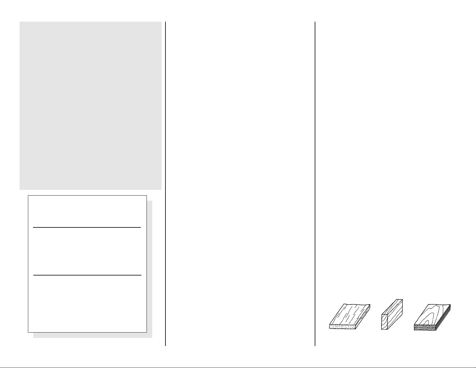
Types of Wood
Balsa Basswood Plywood
Page 6
6
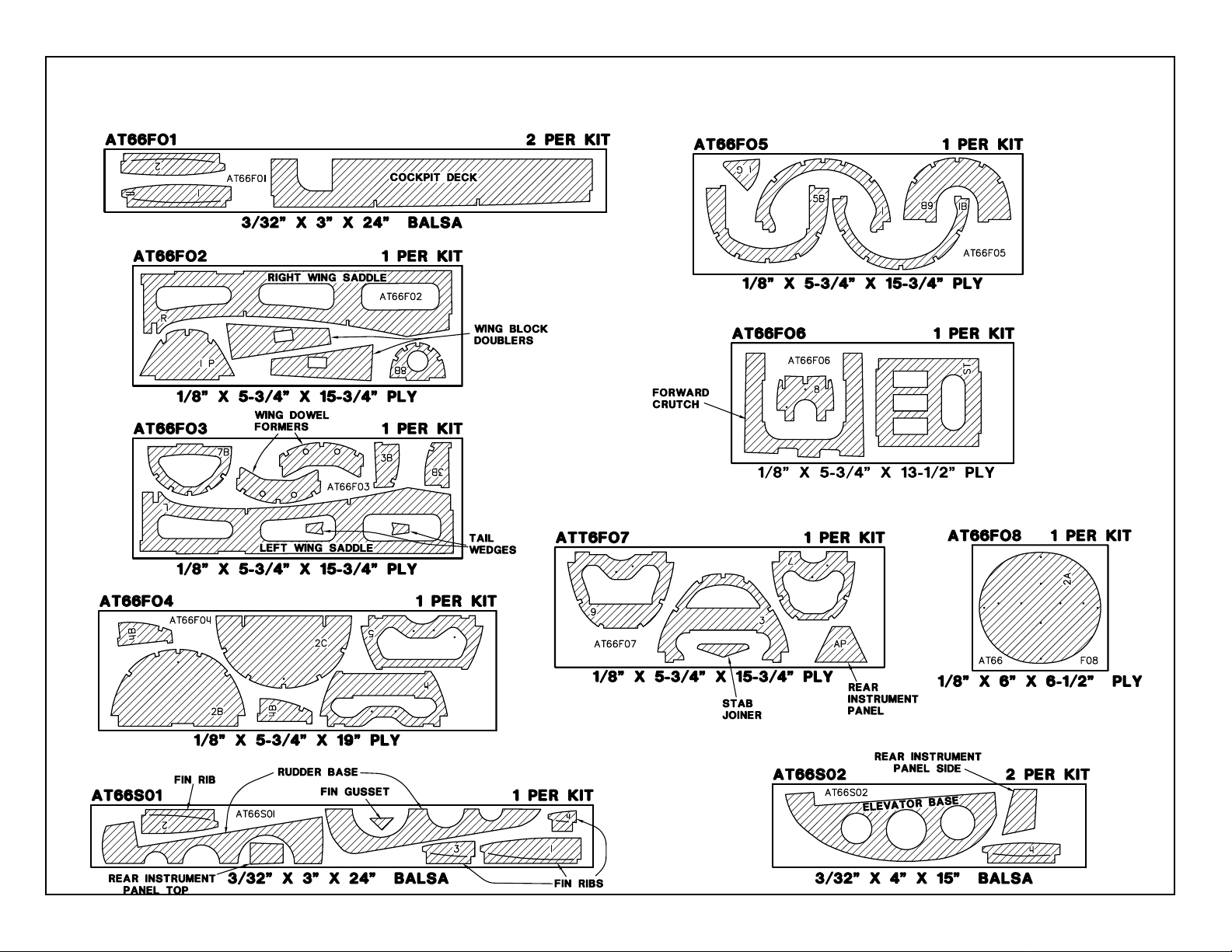
DIE-CUT PATTERNS
Page 7
7
DIE-CUT PATTERNS
Page 8
GET READY TO BUILD
❏
1. Unroll the plan sheets. Re-roll the plans
inside out to make them lie flat.
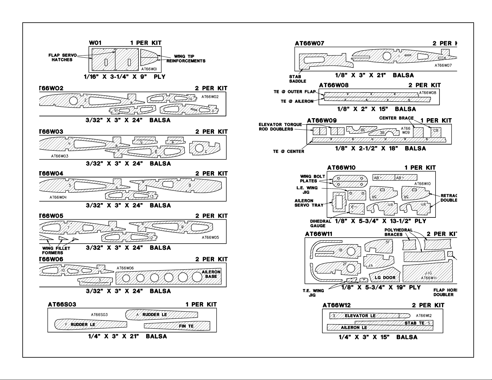
❏ 2. Remove all parts from the box. As you do,
figure out the name of each part by comparing it
with the plans and the parts list included with
this kit. Using a felt tip or ball point pen, write
the part name or size on each piece to avoid
confusion later. Use the die-cut patterns shown
on pages 6 and 7 to identify the die-cut parts
and mark them before removing them from the
sheet. Save all scraps. If any of the die-cut parts
are difficult to punch out, do not force them!
Instead, cut around the parts with a hobby knife.
After punching out the die-cut parts, use your TBar or sanding block to lightly sand the edges
to remove any die-cutting irregularities.
❏ 3. As you identify and mark the parts,
separate them into groups, such as fuse
(fuselage), wing, fin, stab (stabilizer),
and hardware.
BUILD THE TAIL
SURFACES
BUILD THE HORIZONTAL
STABILIZER
❏ 1. Work on a flat surface over the plans
covered with waxed paper. Refer to the plans to
identify the parts and their locations.
❏ 2. Punch out both sets of the die-cut 3/32"
balsa ribs S-1 through S-6. There is a jig tab on
the bottom edge of each of these ribs. If any of
these break off, carefully glue them back on with
thin CA. Lightly sand any imperfections. You
may need to finish cutting the notch in the
forward portion of S-1 for the Stab Joiner (SJ)
with a knife. Use a pen to mark the extensions
of the bottom edge of the ribs across the fore
and aft ends of the jig tabs. These marks will
help when you trim off the jig tabs later.
❏ 3. The stab Trailing Edges (S) are die-cut
from 1/4" balsa. Since some crushing may occur
when die-cutting wood of this thickness, they
are supplied slightly long and can be trimmed.
True up the ends of these pieces with
sandpaper. Also true up the top and bottom
edges of these pieces with a T-bar.
❏ 4. Cut the stab and fin Leading Edges (LE's)
to length from the 1/4" x 30" tapered balsa stock.
Cut these two pieces about 1/4" longer than the
length shown on the plans for the stab LE.
HINT: Bevel the front edge of the stab and fin ribs
to match the sweep angle of the LE stock. This
will give you a better fit and a stronger glue joint.
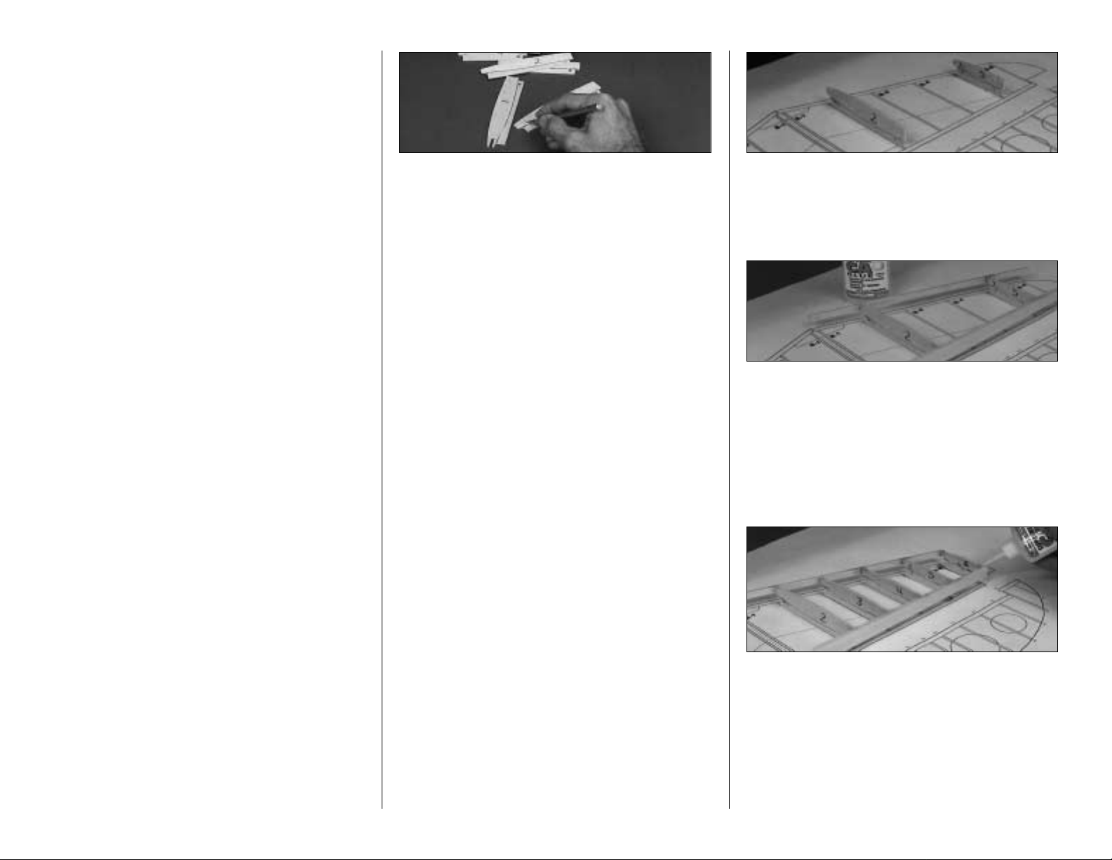
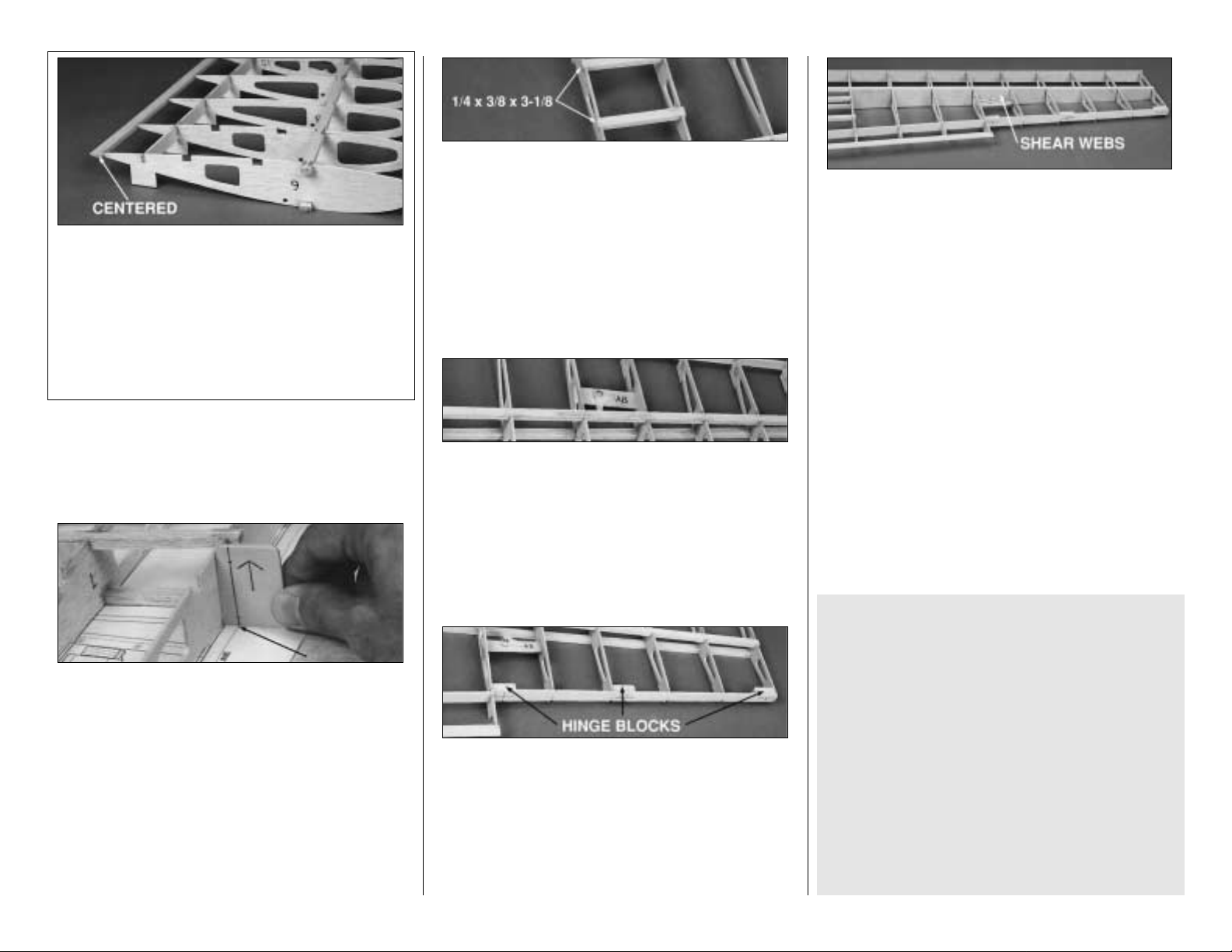
❏ ❏ 5. Starting with the r ight half of the stab,
pin ribs S-2 and S-5 to the building board over
their locations on the plans.
❏ ❏ 6. Center the LE on the front edge of ribs
S-2 and S-5. Glue it in place with CA.
❏ ❏ 7. Center the TE on the back edge of ribs
S-2 and S-5. Glue it in place with CA.
❏ ❏ 8. Glue ribs S-3, S-4 and S-6 in their
places. All of the jig tabs should rest on the
work surface.
❏ 9. Sand the LE and TE near the stab center
so they match the endpoints shown on
the plans.
8
Page 9
9
❑ 10. Repeat steps 5 through 8 to build the left
half of the stab. NOTE: The left half LE and TE
must be sanded for an exact fit with the right
side. They should be glued together along the
center line when you repeat step #6.
❏ 11. Trim the 3/8" x 9/16" x 4-1/32" hard balsa
stab TE Joiner, if necessary, to fit between the
S-2 ribs. Securely glue it to the stab TE and
the S-2 ribs.
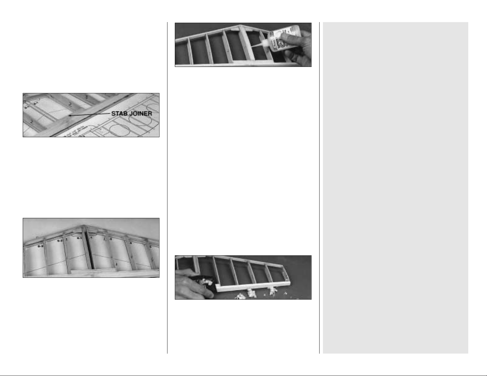
❏ 12. Check the fit of the die-cut 1/8" plywood
Stab Joiner (SJ) and adjust if required for a
good fit with the stab LE. Place the Stab Joiner
into the slots in the two S-1 ribs and work the
whole assembly into position. Make sure all
parts are properly aligned and the S-1 rib jig
tabs contact the work surface. Glue in the Stab
Joiner and the S-1 ribs.
❏ 13. Cut two 1/4" wide cross-grain strips from
a 1/16" x 3" x 30" balsa wing sheet. Glue these
strips between the two S-1 ribs flush with their
top edges. These strips will reinforce the stab
skins where they join at the center and also
strengthen the stab.
❏ 14. Use CA+ to reinforce any glue joints that
don't look strong.
❏ 15. Trim and sand the tip ends of the LE and
TE to match the plans.
❏ 16. Carefully remove the stab from the
building board. Try not to damage the jig tabs as
they will be needed until after the top of the stab
is sheeted.
❏ 17. Use a razor plane and a sanding block to
shape the top surface of the LE (particularly
toward the tip) until it's even with the ribs. Plane
and sand the TE, if required, to smoothly blend
with the ribs.
TIPS FOR MAKING WING AND
STAB SKINS
A. Wherever practical, pre-join the balsa sheets
to make a "skin" before attaching them to the
structure.
B. Many modelers like to sort the wood so they
can put the best wood with the most even grain
structure on the top of the wing and stab.
C. Make your skin larger than needed to allow
for misalignment. On a large surface like the
wing, 3/8" extra is suggested.
D. To make skins, the following steps
are suggested:
1. Tr ue up the edges of the sheets with
a metal straightedge and a sharp knife or a "TBar" sanding block.
2. Test fit the sheets together to make
sure they match well.
3. Glue the sheets together with thin CA
over a flat surface covered with waxed paper. A
quick wipe of the joint with a fresh paper towel
will remove excess glue and make sanding
easier. Mark the poorest surface that you
think should be the inside of the sheet
with an "I".
4. Place the skin on a large, flat surface
and sand it with a large, flat sanding block and
fresh, sharp 220 paper. Use light pressure and a
brisk circular motion.
5. Trim the perimeter of the sheet to
even things out.
Page 10
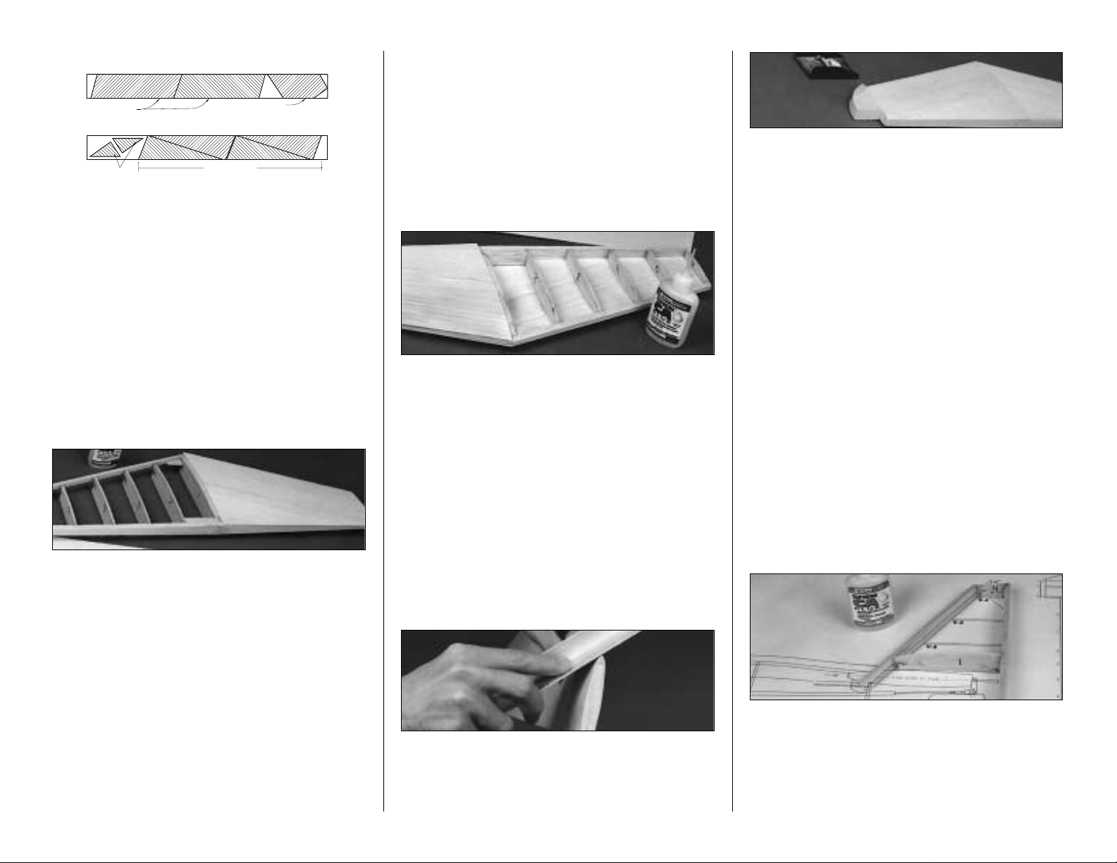
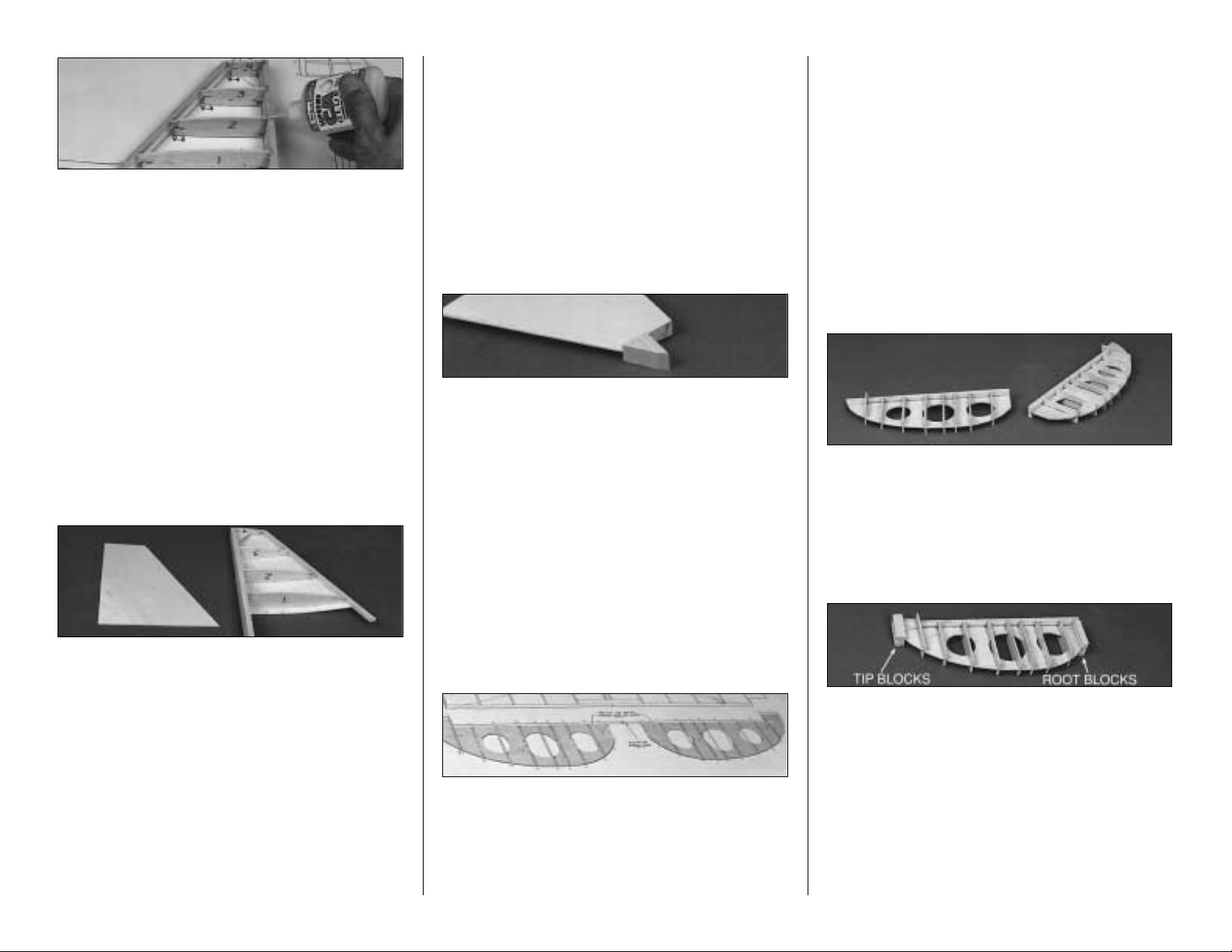
❏ 18. Make four stab skins from three 1/16" x
3" x 30" balsa sheets. See the sketch for the
proper layout on the wood. Refer to the plans for
the exact shapes and sizes, but remember to
make the skins slightly oversize.
❏ 19. Pin the stab str ucture onto your building
surface using pins at the tips and diagonally
under the LE & TE.
Don't hide the pins under
the skin.
Test fit the skins over the structure.
Make sure the skins meet flush at the center.
Adjust them if necessary.
❏ 20. Apply an even bead of medium or thick
CA to the upward facing edges of the structure.
Place a skin in its proper position and press it
firmly down until the glue has set. Repeat this
step for the other top skin.
❏ 21. Remove the stab from the building
board. Trim off the jig tabs with a sharp knife.
Trim and blend the LE and TE to the ribs as
you did before. Check all glue joints, adding
glue as necessary.
❏ 22. Cut two 1/4" wide cross-grain strips from
1/16" x 3" balsa. (You probably have some left
over balsa from the stab sheeting operation)
Glue these strips between the two S-1 ribs flush
with their bottom edges as you did in step #13.
❏ 23. It's important to get a good glue bond
between the stab structure and the bottom stab
skins. Apply a heavy bead of medium or thick
CA to all of the
upward facing
edges of one side
of the stab structure. Place a skin on the
structure and hold it in place with your hands
until the glue sets. Repeat this for the other
bottom skin. Be careful not to bend or twist
the stab during this step.
❏ 24. True up the ends of the stab with a
sanding block. IMPORTANT: Round the LE of
the stab to match the cross section on the plan.
❏ 25. Glue the 5/8" thick shaped balsa Stab
Tips in position. Use a razor plane and a
sanding block to shape them to an airfoil that
matches the stab. You may contour the tips to
their final shape now, or wait until the model is
nearer completion.
BUILD THE FIN
❏ 1. Punch out the die-cut 3/32" balsa ribs V-1
through V-4. Be sure to preserve their jig tabs.
❏ 2. Cut an 8" length of the tapered 1/4" balsa
stabilizer LE stock and sand bevels on each end
to match the plans exactly as the length of the
LE sets the angle of the fin. Notice that the fin
LE protrudes through the stab and fits into a
notch on top of F-8.
❏ 3. Punch out the die-cut 1/4" balsa fin TE
and lightly sand the edges to touch them up.
❏ 4. Pin ribs V-1 and V-4 to the building board
over their proper locations. Center the LE on the
front of the ribs and glue it in place. Center the Fin
TE on the aft edge of the ribs and glue it in place.
10
Two Sheets
Stab Fwd
One Sheet
Fin Tips
Fin Fwd
Stab Aft
Page 11
❏ 5. Put ribs V-2 and V-3 into their places and
glue them to the LE and TE. Remember, all jig
tabs should contact the work surface.
❏ 6. Glue the die-cut 3/32" balsa Fin Gusset
into the corner of V-4 and the Trailing Edge.
❏ 7. Apply extra CA+ glue to any joints that do
not appear to be well glued.
❏ 8. Blend the LE to match the ribs on the
upward facing (left) fin side. Sand the TE, if
necessary, to blend smoothly with the ribs.
❏ 9. Make a skin for each side of the fin using
the 1/16" balsa sheet left over from the stab
skins. Make the skin so it overhangs past V-1
about 5/8"; this will allow fitting to the stab later.
With the structure flat on the table, glue on the
left skin.
❏ 10. Remove the fin from the building board
and trim off the jig tabs. Blend the LE and TE to
the ribs on the right side of the fin.
❏ 11. Use medium or thick CA to glue on the
right skin. Be sure to get a good bond between
the ribs and the skin.
❏ 12. True up the edges of the fin sheeting with
a sanding block. Shape the LE to match the
cross section on the plans.
❏ 13. Glue the shaped 3/4" balsa fin tip to the
top of the fin. Use a razor plane and a sanding
block to do the initial shaping of the tip. Final
shaping should be done later, with the fin taped
to the rudder.
BUILD THE ELEVATORS
NOTE: Build both elevators using
the following steps
❏ ❏ 1. Place the die-cut 3/32" balsa Elevator
Bases (EB) on the plans and mark "Rib"
locations on both sides using the "tick" marks on
the plans.
❏ ❏ 2. Draw a centerline on both sides of the
die-cut 1/4" balsa Elevator LE. Draw two
parallel lines 1/16" away from the centerline on
the aft side.
❏ ❏ 3. Hold the Elevator Base centered
between the lines on the Elevator LE. The
narrow end of the LE is positioned at the
elevator tip . Use CA to glue the Base to the LE.
❏ ❏ 4. Cut "ribs" from the 3/32" x 3/8" x 36"
balsa sticks and glue them onto both sides of
the elevators at the locations you previously marked.
❏ ❏ 5. Glue a 5/16" x 7/16" x 1-3/4" balsa
Elevator Root Block to each side of both
Elevator Bases.
❏ ❏ 6. Glue a 5/16" x 1/2" x 1-1/2" balsa
Elevator Tip Block to each side of both
Elevator Bases.
11
Page 12
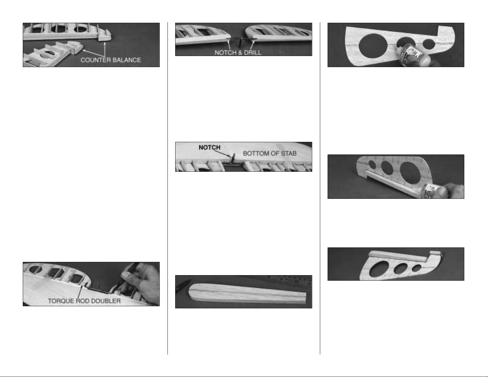
❏ ❏ 7. Center a die-cut 1/4" balsa Counter-
balance on the LE of the elevator tip as shown
on the plans, then glue it in place. Shape the
front of the block to a radius. Allow
approximately 1/16" clearance on the two
matching edges between the counterbalance
and the notch in the stab.
❏ 8. Refer to the photos and the cross sections
on the plans to obtain the shape of the elevator
tips, roots, and ribs. Use a razor plane and
sanding block to "rough in" the shape of the
blocks and ribs. Trial fit the elevators to the stab
for final shaping.
❏ 9. Glue a die-cut 1/8" balsa elevator Torque
Rod Doubler to both sides of the Elevator
Bases as shown on plans and below.
❏ 10. Tape the elevators to the stabilizer. Hold
the bent 1/8" Elevator Joiner Wire and Horn
up to the elevator and mark the location of the
holes (see the plans for the joiner location).
❏ 11. Remove the elevators from the stabilizer.
Drill 1/8" holes in the elevators for the Joiner
wire. Make slots inboard of the holes to allow
the wire to be inset into the elevators. Sand the
Elevator LE to a "V" shape to allow elevator
travel. (See the cross-section on the stab) Test
fit the joiner wire into the elevators. Check to
see that the elevators align with each other
properly. Make adjustments if required.
❏ 12. Mark the location of the Elevator
Control Horn on the TE of the Stab. Remove a
small amount of balsa as shown to allow
clearance for the horn to move freely in both
directions.
BUILD THE RUDDER
❏
1. Glue the two die-cut 3/16" balsa Rudder
LE's together with CA+. Even up the edges with
a sanding block, but save any tapering for later.
❏ 2. Draw centerlines on both forward and aft
surfaces of the LE. Draw two parallel lines 1/16"
away from each side of the centerline on the aft
side that will mate with the Rudder Base.
❏ 3. Glue the die-cut 3/32" balsa FWD
Rudder Base to the die-cut 3/32" balsa AFT
Rudder Base.
❏ 4. Align the Rudder Base over the plans and
mark the "Rib" locations on both sides of the
Rudder Base.
❏ 5. Hold the Rudder Base centered, at a 90
degree angle, to the rudder LE. Apply CA to
the joint.
❏ 6. Center and glue the 1/4" x 3/4" x 1-3/8"
balsa stick Balance Tab LE at the top of the
Rudder Base.
❏ 7. Glue a 1/4" x 1/2" x 2-1/2" balsa stick
Rudder Tip to both sides of the top of the
Rudder Base as shown on the plans.
12
Page 13
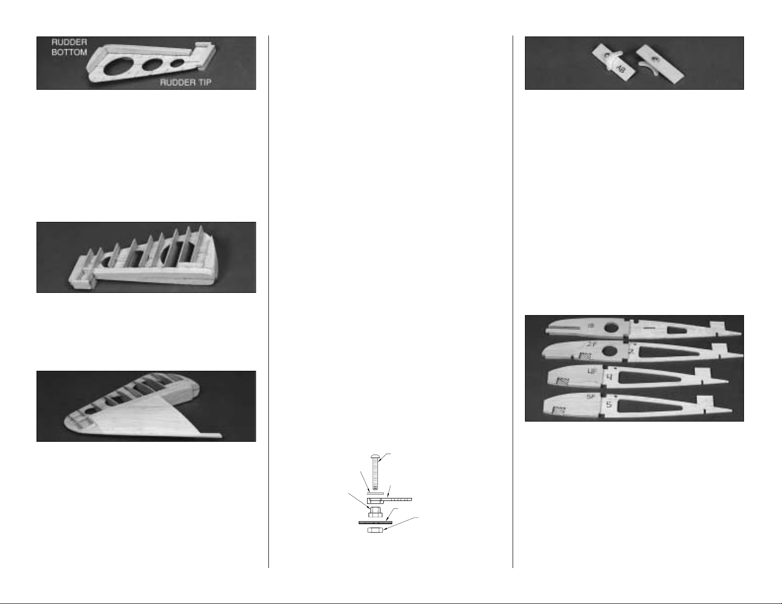
❏ 8. Glue two 5/8" shaped balsa Rudder
Bottoms flush with the bottom edge of both
sides of the Rudder Base.
❏ 9. Glue a 1/2" x 5/8" x 1-13/16" balsa Rudder
Horn and Tail Wheel Block to both sides of the
rudder at the location shown on the plans.
❏ 10. Cut "ribs" from the 3/32" x 5/8" x 36"
balsa sticks and glue them to both sides of the
rudder at the locations you previously marked.
❏ 12. Refer to the photos and the cross
sections on the plans to obtain the shape of the
rudder. Use a razor plane and sanding block to
"rough in" the shape of the rudder. Final
shaping, fitting, and beveling should be done
after the fin is glued onto the fuselage, but you
may wish to tape the rudder to the fin at this
point to blend the upper ends of both.
BUILD THE WING
NOTE: The wing panels are built
"UPSIDE-DOWN" on the plans. The
jig tabs are attached to what is, in
the end, the TOP surface of the
wing. Since it is the standard
convention to show the Top View of
the wing, and the wing panels are
built upside-down, the LEFT wing
panel is built over the RIGHT Wing
Top View and vice-versa. This does
not present any problems; just be
sure to build a left and a right wing.
PREPARATION
❏
1. Locate the four 1/4" x 3/8" x 30" hard balsa
Wing Spars, then cut them to 25-1/2" each.
Save the cut-off ends for the flap servo mounts.
❏ 2. Punch out all the die-cut 3/32" balsa wing
Ribs and 1/8" ply Doublers. Smooth out any
imperfections with sandpaper. Be sure to keep
the jig tabs attached to the ribs.
❏ 3. Ribs W-2 through W-9 have punch
marks just aft of the spar. Drill a 3/16" hole at
each of these marks for future installation of
the aileron pushrods.
❏ 4. Drill 1/8" holes through the punch marks in
the two die-cut 1/8" plywood Aileron Bellcrank
Plates (AB). Assemble the bellcrank parts as
shown in the sketch. Be sure to put a drop of 6minute epoxy on the 4-40 nut and threads to
prevent the bellcrank from vibrating loose.
NOTE: If you haven't already done
so, now is the time to decide which
type of landing gear configuration
you will be using. Fixed or
Retractable?
❏ 5. (Skip this step if installing retracts) If you
chose to build your AT-6 with fixed gear, locate
wing ribs W-1, W-2, W-4, W-5, and plywood
doublers 1B, 2F, 4F, 5F. Refer to the left half of
the center section plans for the proper location of
each doubler, then use CA+ to glue the ribs and
doublers together. Be sure to make a LEFT and
a RIGHT of each rib assembly. Remove the
shaded area with a hobby knife or razor saw to
allow for the gear rails .
13
4-40 x 3/4" BOLT
#4 WASHER
NYLON BELLCRANK
BRASS
BUSHING
PLYWOOD
4-40 NUT
Page 14
❏ 6. (Skip this step if installing fixed gear) If you
chose to build your AT-6 with retractable gear,
locate wing ribs W-1, W-4, W-5, and plywood
doublers 1B, 4R, 5R. Refer to the right half of
the center section plans for the proper location
of each doubler, then use CA+ to glue the ribs
and doublers together. Be sure to make a left
and a right of each rib assembly. Remove the
shaded area with a hobby knife or razor saw to
allow for the gear rails.
NOTE: For retracts, rib W-2 does not
require a doubler.
❏ 7. Finish cutting the slot in the aft por tion of
both W-1 ribs to allow for later insertion of the
Wing Bolt Plate.
Okay, the prep work is behind you, so now that
the dull stuff is done, let's build the outer wing
panels so you'll have something to show when
your friends drop in to check on your progress!
BUILD OUTER WING PANELS
❏
1. Place a wing panel plan on your building
board and cover it with waxed paper.
Cutting the
wing panel sections apart makes handling easier.
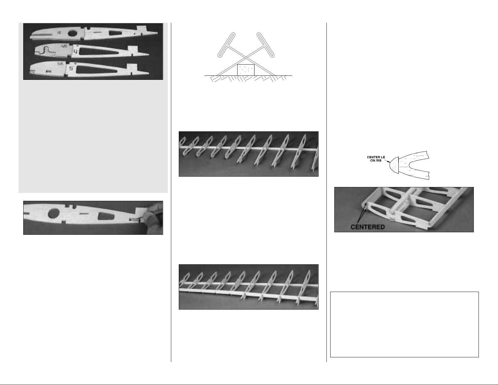
❏ ❏ 2. Pin a Spar to the building board at
three or four locations using the cross-pinning
technique shown in the sketch.
❏ ❏ 3. Position the die-cut 3/32" balsa ribs
W-6 through W-15 on the spar. These should be
vertical and aligned over their appropriate
locations as indicated on the plans.
The jig tabs
located near the aft end of the ribs should all
contact the work surface.
Glue W-7 through W-
15 to the spar. Pin W-6 in place for the time being.
❏ ❏ 4. Test fit the die-cut 1/8" balsa OUTER
TE AT FLAP and TE AT AILERON to the aft
edges of ribs W-6 through W-10 and W-11
through W-15 respectively. The upward facing
edges of the ribs and the top surface of the
trailing edges should be even, and all of the jig
tabs should touch the work surface. NOTE: Both
Trailing Edges taper slightly from one end to the
other. The narrow ends should be located at W-
10 and W-15.
❏ ❏ 5. Sight down the TE of the wing from the
root end; make sure all the ribs are aligned. Use
paper to shim under the jig tabs of any ribs that are
low. When everything looks level, glue the TE's in
place. Once again, don't glue the W-6 rib.
❏ ❏ 6. Press the Spar into the wing notches
and check for a flush fit at each rib. When
satisfied, glue ribs W-7 through W-15 in place.
❏ ❏ 7. Cut a 4" length from each of the two
shaped balsa Leading Edges.
These short
pieces will be used when building the center
wing panel.
Center one of the long LE's
vertically on the front edge of the ribs. Glue it to
ribs W-7 through W-15.
NOTE: Do steps 8 and 9 for a wing
without
operational flaps. Skip the next two steps if
you are building a wing with operating flaps.
❏ ❏ 8. Cut one of the tapered 1/2" x 24" balsa
Flap TE in half, to make two 12" lengths. Note:
This Flap TE is not used if you build operating flaps .
14
Page 15
❏ ❏ 9. Glue the Flap TE to r ibs W-7 through
W-10. The Flap TE should be centered on the
aft edges of the ribs and should be (as shown in
the cross-section on the plans) aligned with the
top and bottom of the ribs. Make sure all the jig
tabs are contacting the table. A metal
straightedge can be placed on the structure over
the jig tabs to hold them down evenly.
Now you'll see why we didn't want you to glue
W-6 in place earlier.
❏ ❏ 10. Draw a line through the two punch
marks on the ply Dihedral Gauge. With the
arrow on the gauge pointing up, position the
gauge on the plan so the line you drew is on the
dashed reference line printed on the plan.
Move the gauge along the reference line and
adjust the angle of W-6 until it's flush with the
gauge from the LE to the TE. After double (
even
triple
) checking that the angle is perfect, glue
W-6 in place at all points of contact.
❏ ❏ 11. Cut the two balsa 1/4" x 3/8" spar cut-
offs to 3-1/8" long. Glue two of these sticks into
the notches in ribs W-6 and W -7. These will act as
supports for the flap servo hatch. If you don't plan
on using flaps, fill the notches with scrap balsa (or
install the rails ev en if y ou won't use them).
❏ ❏ 12. Glue the Aileron Bellcrank assembly
into the slots in ribs W-10 and W-11. The
bellcrank should face away from the building
board as shown in the photo.
❏ ❏ 13. Locate the 3/8" x 1/2" x 15" balsa
Flap & Aileron Hinge Block. Cut six 1" lengths
to use as aileron hinge blocks (save the balance
for use as flap hinge blocks). Glue 3 blocks
where shown on the plans; save the other 3 for
use on the second wing panel.
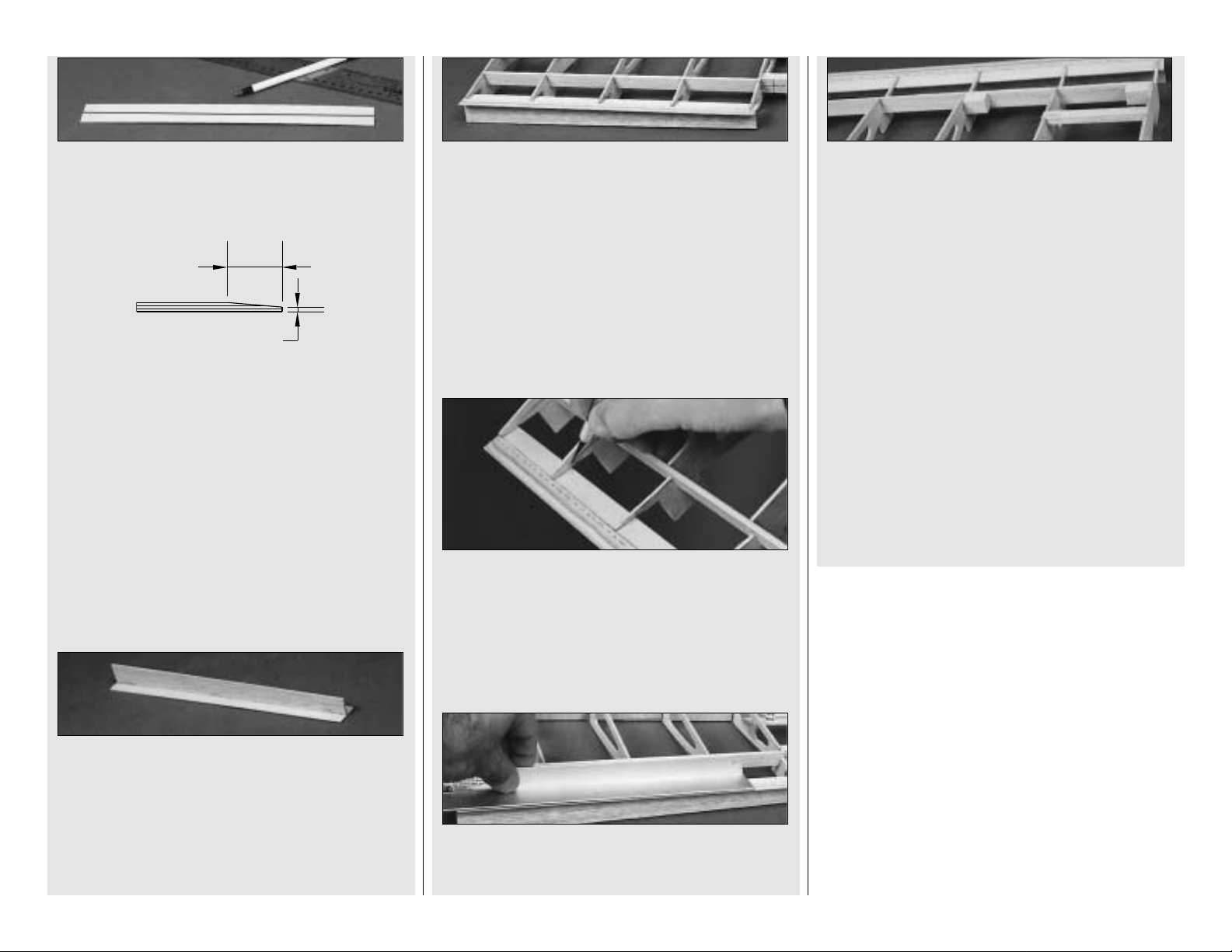
❏ ❏ 14. Tr im the 1/16" x 2-3/4 x 1-11/16"
balsa Shear Webs to fit behind the spar
between ribs W-7 through W-15. Do not install
a shear web between W-6 and W-7. Glue them
in place with CA+. Wick CA between all the
joints of the shear webs and the spars to make
sure they are well bonded. It's not important to
glue the shear webs to the ribs.
If you are building your wing without operational
flaps you can take a short break to admire your
handiwork. When fully revived, clean the
sawdust off your bench, swap the plan sheets,
and get busy building the other outer wing
frame. On the other hand, if you are installing
operational flaps, you still have some more work
to do, so get back to it. You can rest later.
PREPARE THE WING P ANELS FOR
THE FLAPS
Do the following steps if you are building
operational flaps.
❏ ❏ 1. Remove the wing panel from the
building board. Use a T-bar with fresh 220 grit
sandpaper to blend away any unevenness from
the structure. Pay special attention to the trailing
edge of the wing. It's important to make the
trailing edge as straight as possible so the split
flaps will fit well.
15
Page 16
❏ ❏ 2. Draw a centerline down both sides of a
1/16" x 1" x 12" plywood TE Strip.
❏ ❏ 3. Use a T-bar with sharp 150 or 220 grit
sandpaper to bevel the aft 3/8" of the TE Strip
down roughly 1/32".
❏ ❏ 4. Locate the two 3/32" x5/8” x 12" balsa
TE Jig Strips. Check the straightness of these
Jig Strips by holding them on edge on a flat
surface. True them up with a knife and a metal
straightedge if required.
❏ ❏ 5. Place the ply TE Strip with beveled side
down on a very flat table. Glue a TE Jig to the
TE Strip on the centerline. The Jig will keep the
TE straight until the wing is complete. Do not
use excessive glue because it will have to be
sanded off later.
❏ ❏ 6. Glue the TE Strip assembly to the wing
structure with the beveled side up. The aft end
of ribs W-6 through W-10 should align with the
centerline you drew on the TE Strip. Do not
force the ribs to touch the TE Strip. This will
cause the TE to warp when you remove the Jig
later; just fill any slight gaps with glue. NOTE:
The TE Jig is designed to keep the ply TE Strip
from warping.
It's not meant to touch the work
surface so don't be alarmed when it doesn't.
❏ ❏ 7. Use a razor saw and a hobby knife to
trim off the bottom half of r ibs W-6 through W-10.
The bottom side is the side opposite the jig tabs.
❏ ❏ 8. Trim the ends of the TE Strip flush with
the W-6 and W-10 ribs.
❏ ❏ 9. Use a T-bar sander to even up the ribs
inside the flap bay.
❏ ❏ 10. Cut the remainder of the 3/8" x 1/2" x
15" stick (that you used to make the aileron
hinge blocks) into ten 3/4" pieces. Fit and glue
three of these pieces where shown on the wing
plan. Save the remaining blocks for use on the
other two wing panels. Mark the location of the
hinge blocks on the outside of the TE spar to
help you find them later.
Repeat the previous instructions to build the
other outer wing panel.
Congratulations! Even though building
operational flaps requires a little bit of patience
and a lot of elbow grease, you will be rewarded
by more scale appearance and slower landings
than the less ambitious modeler. If that isn't
enough, they just look great during slow fly-bys.
BUILD THE CENTER SECTION
❏ 1. Cover the Center Wing Panel plan with
waxed paper, then pin a 1/4" x 3/8" x 18" balsa
Spar in position over it.
❏ 2. Locate both of the W-1 Rib Assemblies
(if the ply doublers are not glued in place yet,
do it now)
and position them on the spar with
the jig tabs pointing down. Don't glue the ribs
in place yet.
16
3/8"
1/32"
Page 17

❏ 3. Work the die-cut 1/8" ply Aileron Servo
Tray into the slots in the W-1 ribs where shown
on the plans. The punch mark on the tray must
be positioned toward the leading edge. When
installed correctly, there should only be a 1/16"
gap between the edge of the Servo Tray and the
Spar. This gap will allow a Shear Web to be
inserted later. When satisfied with the alignment
of the ribs and the Servo Tray, glue everything in
place with CA.
❏ 4. Slightly round one end of both 1/4" Wing
Dowels. Test fit the Wing Dowels into the slots
in both W-1 ribs with the round end facing out. If
needed, lightly sand the openings for a good fit.
Slide the die-cut 1/8" ply Dowel Jig over the
dowels to set the correct spacing between them.
Use 6-minute epoxy to glue the Dowels into the
slots. During this step don't worry about which
end of the Dowel Jig is facing the work bench.
You are only setting the horizontal spacing.
❏ 5. Glue the two die-cut 1/8" balsa Center
Brace (CB) squares together along one edge.
The grain must run across the narrow dimension.
❏ 6. Check the fit of the Center Brace between
the dowels. Sand the edges for a snug fit. Use 6
minute epoxy to glue it to the dowels with liberal
fillets of epoxy around the joints. When the
epoxy has cured, remove the dowel jig but save
it for use during the wing sheeting process.
❏ 7. Glue the two die-cut 1/8" ply Wing Bolt
Plates together with CA. Slide the joined Plate
through the slots in the aft end of the W-1 ribs
but don't apply glue yet.
IMPORTANT
THE STEPS PRINTED IN THE SHADED
BOXES ARE FOR BUILDING YOUR AT-6 WITH
RETRACTABLE LANDING GEAR.
SKIP THE
SHADED INSTRUCTIONS IF YOU WILL BE
INSTALLING FIXED GEAR
.
❏ 8. (For FIXED GEAR only) Pin Rib
assemblies W-2 , W-4, and W-5 on the Spar. Be
sure the 2F, 4F, and 5F Ply Doublers are facing
the correct direction. Make sure that the jig tabs
are in contact with your work surface and that
the tips of their trailing edges are aligned. Use a
small triangle to hold the ribs vertical, then glue
them to the Spar.
❏ 8. (For RETRACT GEAR only). Pin Rib
assemblies W-2, W-4, and W-5 on the Spar. Be
sure that the 4R and 5R Ply Doublers are
facing the correct direction. Make sure that the
jig tabs are in contact with your work surface
and that the tips of their trailing edges are
aligned. Use a small triangle to hold the ribs
vertical, then glue them in place.
17
Page 18

❏ 9. Inser t the die-cut 1/8" slotted balsa TE AT
FLAP CENTER into the notches along the TE of
the wing ribs. If necessary, adjust the depth of
the notches to allow the slotted TE to fit flush
with the upward-facing rib edges. Glue the TE in
place when you are satisfied with the fit.
❏ 10. Adjust the Wing Bolt Plate so that it
matches its position over the plans, and is
parallel to the TE. Glue it to both of the W-1 ribs
and the TE. Use thick CA or epoxy to create a
fillet along all points of contact.
❏ 11. Glue the upper 1/4" x 3/8" x 18" balsa
Spar in place.
❏ 12. Fit the die-cut 3/32" balsa W-3 ribs
between the spars. Make sure that the Landing
Gear Rail notch is pointing away from the work
surface. Butt the ribs firmly against both Spars
and glue them in place.
❏ 13. Use medium CA to glue the die-cut 1/8"
ply Leading Edge Braces together (two pieces
per assembly), then glue the assemblies into the
notches in W-1 and W-2 and also to the side of
W-3 as shown.
❏ 14. Center the shaped Leading Edges (Cut-
offs from the outer wing panels) vertically on the
front edges of ribs W-3, W-4, and W-5, then glue
them in place.
❏ 15. Cut one 3-5/8" Forward Sub-Spar from
each of two pieces of 3/16" x 3/16" x 36" balsa
fuselage stringer. Test fit the these short spars
between Rib W-1 and the inside edge of the
Leading Edge Brace. Glue them in place when
satisfied with the fit. (See photo at step 16)
Skip the next four steps if you will be
installing retract gear.
❏ 16. Test fit the two 1/2" x 3/4" x 5-3/4" grooved
Landing Gear Rails into the notches in ribs W-2
through W-5. The fit should be snug, and the
groove should be facing away from the work
surface. Use 30-minute epoxy to glue the Rails in
position. Be sure that the outer edge of the Rails
are flush with the outside of the W-5 ribs.
❏ 17. Carefully remove the wing center panel
from the work surface. Use 30-minute epoxy to
glue the two 1/2" x 3/4" x 1" Maple Landing
Gear Blocks to the top of the Rails and the
sides of the W-2 ribs doublers.
❏ 18. Draw a line 5/16" from the inside edge of
the Grooved Rail.
❏ 19. Carefully drill a 3/16" diameter hole on
this mark, all the way through the Maple Block
with the drill bit angled slightly as shown in the
photo. Protect your work surface with a piece of
plywood underneath the drill bit.
18
Page 19

❏ 20. NOTE: perform this step regardless of
landing gear configuration. Glue the die-cut
1/8" balsa Half-rib W-3B to the top half of W-3
as shown on the plans. Make sure that it's flush
with the contour of W-3.
❏ 21. (Retract Gear) With the center panel
pinned to the work surface, insert the two 1/4" x
1/2" x 2-1/2" ply Landing Gear Rails into the
notches in ribs W-4 and W-5. Test fit the retract
mechanism (without the struts in place) and
make any adjustments required for a good fit.
Don't cut out the wheel wells in W-2 just yet;
we'll get to that after sheeting the bottom of the
wing. When everything fits well, use 30-minute
epoxy to glue the Rails in position. Be sure that
the outer edges of the Rails are flush with the
outside surface of the W-5 ribs.
❏ 22. Use scrap balsa to build a supporting
base for the sheeting, as shown in the photo.
❏ 23. Do this step if you are NOT installing
operational Flaps.
True-up the aft edge of the ribs with a
straightedge and T-bar sander. Cut the 1/2" x
24" tapered balsa Trailing Edge to 17", then
glue it to the ribs. The TE should be centered on
the aft edges of the ribs and should be aligned
as in the cross-section with the top and bottom
of the ribs. Make sure all the jig tabs are
contacting the table. A metal straightedge can
be placed on the structure over the jig tabs to
hold them down evenly during this step.
For operational flaps, perform steps 1 - 10 on
page 15-16, applying the same techniques to
the center panel. Substitute 18" pieces
where 12" lengths are specified. Note: The
next photo shows the ply TE installed, but
the ribs have not yet been trimmed out.
❏ 24. Glue 1/16" balsa Shear Webs to the
front and rear of the center panel main Spars
between all ribs except W-4 and W-5.
❏ 25. Trim the Spars, LE, and TE flush with the
outside edges of the W-5 ribs. Lightly sand the
top, bottom, and ends of the center panel to
blend the ribs with the Spars and to remove any
excess glue.
PREPARE THE POLYHEDRAL
BRACES
❏ ❏
1. Position the 1/8" ply Polyhedral Braces
over the sketch on the plans. Look carefully at
each piece and you will notice that one end is
slightly tapered. This is the end that plugs into
the outboard panel. After you align each piece
over the drawing, mark an index line on each part
as shown, then extend it around to both edges.
19
Page 20

❏ ❏ 2. Without gluing, stack the three Braces
together and compare the assembly with the
drawing. Repeat this process with the second
set of braces,
but this time flip the pieces over
when you stack them. You should now have a
right hand and a left hand set of braces, as
shown in the photo.
Tracing around the edges of
the two shorter parts will help alignment when
you glue them together.
❏ ❏ 3. When satisfied that the braces are
accurate, use 6 minute epoxy to glue the par ts
together.
JOIN THE WING
❏ ❏
1. Carefully remove a 3/8" wide strip of
balsa between the spars on both W-5 and W-6
ribs. This will allow the Polyhedral Braces to be
inserted and glued between the spars.
❏ ❏ 2. Test fit the Polyhedral braces into the
center and outboard wing panels, sanding if
necessary for a good fit. The wing panels should
mate evenly along the joint without any
unnecessary twisting or bending to line things up.
If you have to force the panels to fit, locate the
problem and fix it before proceeding. Any
twists will become a permanent part of the
structure after the panels are joined and will be
difficult to correct.
❏ ❏ 3. Use only a spot of CA to glue the two
1/4" x 1-7/16 " x 7-1/2 " balsa Wing Jig Blocks
to the W-4 ribs. Glue the blocks to the W-4 jig
tabs and the top of the spar.
Now for the hard part, cleaning a space on your
work bench large enough to spread out and join
the wing.
IMPORTANT: Check your work surface with a
metal straightedge to make sure that it's
perfectly flat before proceeding. Make a "dry
run" of the following step before actually
performing it with glue.
❏ ❏ 4. Place the Center panel on the Jig
Blocks in the middle of your work bench. Add
some weight to hold it in place (phone books or
small sandbags are handy for this). Prepare 1/2
ounce of 30 minute epoxy. Liberally apply the
epoxy to the W-6 Ribs and Polyhedral Braces.
Plug the Braces into the Outboard panels. Plug
the Outboard Wing Panels into the Center
section and align the Ribs for a flush fit.
Don't
worry about the exact alignment of the leading
edge. If you didn't glue the Leading Edges
exactly centered on the ribs they won't match.
After the wing is sheeted, the LE joints will be
blended with sandpaper.
Once all the panels are
in position, clamp the ribs together and align the
Polyhedral Braces between the Spars as shown
on the top view of the plans. Put weights on the
two W-15 ribs to hold the jig tabs and Spars on
the work surface. Before the epoxy kicks off,
double check your work. Fill any gaps
between spars with 30 minute epoxy
SHEET THE BOTTOM OF THE
WING
Our suggested wing sheeting process allows
you to sheet the wing panels with one skin per
side. This technique is better than sheeting the
wing with individual sheets, and allows you to
pre-sand all of the seams that will be over
open structure.
All balsa sheeting will usually bend when it's cut
from the log since stresses are relieved. For the
best results, trim the edges of the wing sheeting
with a long metal straightedge and a sharp knife
before joining them.
NOTE: Do the following steps for
both the right and left wing panels.
❏ 1. Sort through the remaining 1/16" x 3" x
30" balsa and pick out the 6 best sheets to be
used for the top surfaces of the outboard wing
panels. Pick out the 4 best 1/16" x 3" x 18"
sheets to use on the top of the center section.
❏ 2. Lay waxed paper over a flat, smooth
work surface.
20
Page 21

❏ 3. Make four outboard wing skins by edge
gluing three 1/16" x 3" x 30" balsa wing sheets
together to make (4) 9" x 30" skins. Make two
center section skins using four sheets of 1/16"
x 3" x 18" balsa to make two 12" x 18" skins.
Refer to page 9 for tips on making skins.
NOTE: The steps below show the
sheeting of a wing with functioning flaps.
Wings without functioning flaps are sheeted the
same way, but they will look slightly different.
❏ 4. Tape a center section skin to the bottom
surface of the wing with one edge butted up to
the LE. Mark the aft edge of the sheet (along
the flap line or
along the inside of the tapered
TE if no flaps are used
) from the opposite side
with a pen. Cut the skin close to the correct size
then sand it for an exact fit. The side edges of
the skin should be centered on the joint
between ribs W-5 and W-6.
❏ 5. Glue the center skin in position using
Medium or Thick CA. Hold the skin in contact
with structure until the glue is dry. Glue a
separate piece of 1/16" x 3" x 9-1/2" balsa (cut
from a 30" sheet) to the forward, wheel well
portion of the center panel.
❏ ❏ 6. Fit one of the 9" x 30" skins in place on
an outboard wing panel, with one long edge
butted tightly against the LE. The inboard edge
should overlap the center section. Tape the skin
in place. With a flexible ruler, mark the edge that
mates with the center panel. Flip the wing over
and mark the tip and TE from the back side.
Allow an extra 1/4" around these two edges.
Remove the skin and cut it to the marked size. If
necessary, use 220 grit sandpaper to
fine tune
the inboard edge for an exact fit.
Hint: The best balsa filler, is no balsa filler!
Take
you time fitting all sheeting and skins in place.
With a little bit of careful sanding you will be
rewarded with perfectly matched joints and a
lighter, stronger airframe.
NOTE: Make a "dry run" of steps 7
and 8 before actually performing
them with glue.
❏ ❏ 7. Position the skin up against the LE,
then glue it to the LE with Thin CA. Blot any
excess CA with a paper towel or tissue.
❏ ❏ 8. Gently lift the skin and, wor king quickly,
apply a bead of Thick CA (also known as CA- )
to the structure that the skin will touch. Hold the
skin in position and press it into place.
Important: Before the CA sets, weight down
the center panel and the TE of W-15 to set the
washout angle
❏ ❏ 9. Sheet any remaining openings in the
bottom wing skin such as around the TE and
non-operational flaps.
❏ ❏ 10. Repeat steps 7, 8, and 9 for the other
outer wing panel.
❏ ❏ 11. Turn the wing over and place it on
foam rubber or a soft surface to avoid premature
hangar rash.
Use the plans to help you locate
the aileron pushrod exits. Cut a 3/16" x 3/4" exit
hole in each outboard panel. Reinforce the skin
around the openings (from the inside) with small
strips of 1/16" scrap balsa.
❏ ❏ 12. Use a sharpened piece of wire to bore
small holes through the skin from the inside to
mark the location of the flap servo hatches and
retract rails. If you will be using fixed gear, mark
the location of the landing gear wire by twisting
a 3/16" drill bit through the top of the torque
block and out through the sheeting. Starting
from the hole you just made, cut away a 3/16"
wide strip of sheeting above the groove in the
landing gear block.
21
Page 22

❏ ❏ 13. Rough cut the hatch openings on the
inside of your guide holes, then use a 1/16" ply
Hatch Cover to mark and cut the full size
opening.
Remember, it's faster to enlarge a hole
that's too small than to shrink one that's oversize.
❏ ❏ 14. If you will be installing retracts,
remove enough material to install the
mechanism and air cylinder, but leave final
fitting of the gear struts and wheels until later.
❏ ❏ 15. Screw a Nylon Clevis onto a 4" Wire
Pushrod. The threaded portion of the wire
should be flush with the inside edge of the
clevis. Make a 90 degree bend 3-1/8" from the
clevis pin. Cut off the excess wire, 1/4" past the
bend. Make a second pushrod in the
same manner.
❏ ❏ 16. Insert the aileron pushrod through
the access hole in the skin and poke it through
the bellcrank from the top. Hint:
Use a 5/64"
drill bit to enlarge the hole where the aileron
pushrod will connect with the bellcrank.
Attach
a Nylon Faslink to secure it in place. Repeat
this step for the other wing panel. If necessary,
hollow out a small indentation on the underside
of the ply to prevent the Faslink from catching.
❏ ❏ 17. Cut the two 24" Plastic Outer
Pushrod Tubes to a length of 15-1/2". After
roughening the outer surface of the tubes with
sandpaper, push them through the 3/16" holes
that you drilled earlier during construction. Refer
to the plans for exact location, but generally they
run from W-2 to W-9. When positioned, spot
glue them to each rib with Medium CA.
❏ ❏ 18. Screw a Nylon Clevis onto the
threaded ends of two 36" wire pushrods. As
before, the threads need to be into the clevis
about 1/4", or flush with the inside opening. Cut
the pushrods down to 22-1/2". Cut ten 3/16"
lengths of inner plastic pushrod tube, then slide
them onto the wire as shown on the plans. If they
are too loose, apply a drop of CA to secure them
in place. If too tight, cut them a little shorter.
Carefully insert the pushrod wires into the
tubes from the W-11 ribs towards the center.
Hook-up the clevises to the bellcranks and
check for free movement.
❏ ❏ 19. Position the aileron (outer) pushrod
clevis pin approximately 1/16" behind the TE
and tape it in position against the underside of
the wing. The bellcranks should be neutral.
Repeat this step for the other wing panel.
❏ 20. Screw Threaded Brass Couplers all the
way into both ends of a Nylon Dual
Aileron Coupler.
❏ 21. Hold the pushrods together at the center
of the wing and draw a line across both
pushrods at the center of the servo opening.
Hint:
It helps to drop a servo into position to
help with this alignment procedure
. Hold the
Aileron Coupler on the pushrods with the Ball
22
Page 23

Socket aligned with the center marks. Draw a
line on the pushrods at the end of each Brass
Coupler. Cut off the ends of the pushrod wires
1/4" towards the center from the marks. File off
any burrs and test fit the assembly.
TIPS FOR SILVER SOLDERING
Use this process when soldering metal to metal
such as brass tube to wire, or pushrod ends
to wire.
A. Thoroughly clean the items to be soldered
with alcohol or degreasing solvent. Pay special
attention to the inside of the Threaded
Brass Couplers.
B. Roughen the area to be soldered with fine
sandpaper, then clean again.
C. Assemble the items to be soldered.
D. Apply a small amount of soldering flux. Acid
based flux works best when one or more of the
items is steel.
E. Heat the metal with a soldering gun or iron,
and apply solder to the metal. The metal must
get hot enough to melt the solder and the solder
must flow freely into joint.
F. Do not move the parts until the solder
has cooled.
G. Test the joint by pulling hard.
H. Clean off the excess flux with alcohol or
solvent. Coat the parts with a very fine film
of oil.
❏ 22. Unscrew the Threaded Brass Couplers
from the Dual Aileron Coupler to prevent the
Nylon from melting, then silver solder them to
the pushrod wires. Unsnap the Clevises from
the Bellcranks and screw the Dual Aileron
Coupler back on the Threaded Brass Couplers.
Reconnect the Bellcranks to the pushrods and
make final adjustments to center the ball
socket and align the Aileron Pushrods at
the TE.
❏ 23. Use a sharpened piece of wire to bore
through the exposed side of the Wing Bolt plate
to mark the holes in the bottom wing skin for
the wing bolts. Mark these holes now as it will
be difficult to find the location after the top wing
skin is applied. Open up the holes on the bottom
side with a Dremel drum sander.
❏ 24. If you are planning on using operational
flaps, you can simplify the job of "fishing" the
servo wires through the enclosed wing with a
little preparation. Tie one end of a 24" length of
string to a 5" long scrap balsa stick. Thread the
string through the wing rib holes between both
servo hatch openings and tie another stick to
the other end. Secure the excess string in the
aileron servo compartment. When the time
comes to thread the servo wires, just tie them to
the string and pull them through to the center
compartment.
SHEET THE TOP OF THE WING
NOTE: This kit includes a special set of wing
jigs to hold the wing at the proper washout
angle (2 degrees washout at each tip) while you
apply the top skins. Twisted wings are a major
cause of bad flight characteristics. Polyhedral
angles can vary slightly, so if your tip jigs require
adjustment, just be sure that both tip jigs are
modified the same, and are therefore identical.
Be careful not to change the washout angle (the
negative angle of attack of the tip ribs) if you
adjust the jigs.
❏ 1. Carefully remove the two 1/4" balsa wing
jigs from the wing. Tr im off the jig tabs from W-1
through W-15. Blend away any inconsistencies
in the top wing surface with a T-bar and 220 grit
sandpaper. Check around each rib at the LE for
glue blobs and remove them with a hobby knife
or sandpaper.
❏ 2. Slide the die-cut 1/8" plywood LE Jig over
the dowels, with the flat edge towards the
sheeted bottom side of the wing.
❏ 3. Glue the die-cut 1/8" plywood TE Jigs
together. Draw a reference line through the two
punch marks as shown in the photo.
23
Page 24

❏ ❏ 4. Use the reference line you drew to
align the TE Jig with the TE at Flap Center. Tack
glue the TE Jigs to the bottom skin under the W-4
Ribs. If you are not using flaps, and the TE has
been sheeted, you can find the location of W-4
by using a pin or a sharpened wire to poke a
small hole through the skin from the top at
the correct spot.
❏ ❏ 5. Place a die-cut 1/8" plywood Tip Jig
under each W-15 rib. You should tape or tack
glue the Jig to the wing.
❏ ❏ 6. Check the fit of an outboard skin to the
wing structure. Make adjustments if required to
fit flush with the LE. Sand a slight bevel to the
edge of the skin that will contact the LE to allow
for a better gluing surface. Once a good fit is
obtained, mark and cut the inboard edge of the
skin so that it will fall on the joint between
W-5 and W-6.
❏ ❏ 7. Hold the skin in place, butted firmly
against the LE, then wick Thin CA into the joint.
Wipe off any excess glue before it dries.
❏ ❏ 8. Gently lift the skin and apply a bead of
Thick CA (CA-) to each rib. Apply glue to the
Main Spar and the TE at the Flaps and Aileron
last. Roll the skin into position and smooth it into
contact with the underlying structure. Add
weights to the entire top of the wing while the
glue dries. A small stack of magazines are ideal
for this purpose as they will match the contour of
the wing.
9. Repeat steps 6,7, and 8 for the other panel.
❏ 10. Measure and cut a 1/16" balsa sheet to
fit the openings at the aft end of the wing skins.
When satisfied with the fit, glue them in place.
❏ 11. Cut the top center panel skin to the
dimensions shown in the sketch. When cut,
the skin will be slightly larger than the
opening to allow for the edges to be trimmed
to the exact size.
❏ 12. Lightly rub some chalk along the top
edge of the outboard panel skin. Tape the aft
edge of the center skin in position along the ply
(or tapered balsa) TE. By pressing the center
skin down over the chalked edges, and rubbing
your finger over the seam, you will transfer an
exact outline in chalk to the center skin. Trim
away the excess balsa with a hobby knife, then
sand with 220 grit for a precise fit. Fit the LE of
the sheet by trimming a little at a time. Do not
glue it in place yet. Tape the center skin in
position for the time being.
❏ 13. Remove the excess plastic from around
the perimeter of the Wing Center Fairing. (See
photo at step 16) Score the plastic with a hobby
knife then flex the plastic until it breaks off. Trim
the Fairing to the embossed outline that can be
found on the inside of the part. Tr y to make nice
straight edges as you will cut the balsa skin to
match the Fairing.
❏ 14. Drill two 5/16" holes in the Fairing to allow
the wing dowels to poke through. The Center
Fairing has been marked with the proper location
for the holes, but building variations may require
that you enlarge the holes for a good fit.
24
3-3/4"
3"
11-3/4"
17"
3-3/4"
Page 25

❏ 15. Remove balsa from the LE to a depth of
about 1/16" at the point where the Center
Fairing fits against it.
❏ 16. Hold the Center Fairing in position, then
trace around the perimeter with a pen. Cut away
the excess balsa, then check the Center Fairing
for fit.
❏ 17. Glue the center panel balsa skin to the
ribs and spar with Thick or Medium CA.
❏ 18. Using the plans as a guide, cut the
opening in the top of the wing sheeting for the
aileron servo. Hint:
Make a small opening to
start with, then work outward until the correct
size is reached.
❏ 19. If you will be installing retracts, drill a 1/2"
hole through the top of the Center Fairing
roughly 3/4" forward of the spar, centered
between the W-1 ribs. This hole will allow
passage of the retract air tubes.
❏ 20. Roughen the inside of the plastic Center
Fairing with coarse sandpaper, then glue it in
position with Medium CA.
At this point you should have the main wing
structure fully sheeted. You may now remove all
Jig parts from the wing and sand off any
glue marks.
WING COMPLETION
❏
1. Mark and cut 1/4" clearance holes for the
wing bolts from the bottom, through the top wing
skin. Hint:
A 1/4" drill bit will do the job but it
may tear up the sheeting as it exits. A round file
or Moto-Tool with a small cutting tip will do a
neater job.
❏ ❏ 2. Trim the sheeting where it protrudes
past the edge of the structure.
❏ ❏ 3. Razor plane and sand the wing
Leading Edge until it blends well with the
sheeting to form a smooth airfoil. Final sanding
of the LE near the tip should be done after the
tip block has been installed.
❏ ❏ 4. Square off the tip of the wing with a T-bar.
Before attaching the Wing Tip Blocks you need
to insert die-cut 1/16" ply Reinforcement pieces
into the TE of each tip. Do this as follows
:
❏ ❏ 5. Tack glue the shaped 1" balsa Wing
Tip to the tip of the wing as shown on the plans.
The bottom of the Wing Tip must be flush with
the bottom of the wing, aft of the spar. Place a
ruler on the top of the wing and extend it back to
the TE of the Wing Tip. Draw a line to match the
airfoil as shown in the photo. Repeat for the
other Wing Tip.
❏ ❏ 6. Remove the Wing Tips. Draw a line
from the center point of the airfoil height to
the center of the TE.
❏ ❏ 7. Transfer these lines to the outside
edge of the Wing Tip. A piece of masking tape
can act as a straightedge to help draw the line
around the curve.
25
Page 26

❏ ❏ 8. Cut a 1/16" slot through the line you just
drew.
If a band or scroll saw isn't available use a
razor saw or hacksaw blade
. Glue the 1/16" die-
cut ply Wing Tip Reinforcements in place.
❏ ❏ 9. Glue the Wing Tip Blocks to both W-15
ribs. Shape the Wing Tip with a razor plane and
a sanding block. Don't do the final shaping of
the aft portion of the tips until the ailerons are
built and taped in position.
Time to celebrate! Your wing is almost done and
it looks great, doesn't it? Invite your buddies
back to the shop for a progress update. Also,
your floor needs sweeping.
NOTE: If you are not building
operational flaps, skip the following
section and proceed to build the
ailerons.
BUILD THE FLAPS
NOTE: The following instructions show
the center flap being constructed. The two
outboard flaps are built using the same
procedure, only the length is different.
❏
1. Place the Flap section of the plans on a
flat work surface and cover it with waxed paper.
❏ 2. From a sheet of 1/16" x 3" x 30" balsa, cut
two strips exactly 1-1/16" wide x 30" long.
❏ 3. Place one of the 1-1/16" balsa strips on
the Center Flap plan, aligned along the LE. Cut
the length to match the plan. Pin it in place.
❏ 4. Cut the Aft Flap Section from a 1/16" x 1"
x 18" ply strip to match the plans. Draw a line
lengthwise on one surface of the ply, 3/8" from
the TE. Butt the ply against the forward balsa
strip and if necessary, lightly sand the edges for
a good fit but don't glue it in place yet.
❏ 5. Using a T-bar and sharp sandpaper, taper
the ply strip from the centerline to the TE. The
finished edge should be approximately 1/32"
thick.
❏ 6. Glue the ply Aft Section to the Forward
balsa strip. The beveled edge of the ply must
be towards the TE, facing up. Use the tic
marks on the plans to mark the Rib and Spar
locations. The Ribs do not go all the way to the
TE of the ply.
❏ 7. Cut the Center Flap LE from a 3/16" x
1/4" x 24" balsa stick to match the plans. Glue
the LE to the top of the sheeting.
❏ 8. Locate the 3/32" x 1/4" x 1-1/2" flap ribs.
Glue the Ribs to the sheeting at the locations
you marked earlier. Note: The ribs may be
angle cut before gluing, or sanded to shape
after assembly.
❏ 9. Cut and glue pieces to form the Flap
Center Spar from 1/8" x 3/16" x 24" balsa to fit
between each Rib.
❏ 10. Use a T-bar with 220 grit to sand the Ribs
and Spar to an even taper from the LE to the TE.
Be careful not to sand off too much material.
26
LE
Page 27

❏ 11. Fit and glue a 1/32" x 3/16" x 18" ply Cap
Strip to the length of the Center Spar and also
to the top of the Leading Edge Spar. Hold a
straightedge over the Cap Strips while the glue
cures. The Cap Strips will help prevent the flap
from warping.
❏ 12. Locate the four 3/32" x 1-1/4" Brass
Flap Joiner Tubes.
Two of these will be used
on the center Flap, and one on each of the
outboard Flaps.
❏ 13. Notch the two end ribs just behind the
center spar to accept the diameter of the Brass
Flap Joiner Tubes. Make sure that the tubes rest
evenly on the sheeting. Roughen the tubes with
220 grit sandpaper, then glue them to the
sheeting, flush with the outside edge, with
Medium CA.
❏ 14. Cut ten 3/16" x 3/4" x 3/4" Hinge Blocks
from the 3/16" x 3/4" x 8-7/8" balsa stick. Four of
these Blocks will be used for the Center Flap.
The remaining six are for use on the two
Outboard Flaps. Refer to the plans for the
location of the Hinge Blocks, then glue them
between the Ribs, to the sheeting and spars. It's
necessary to cut a bevel on one edge of the two
outboard Blocks to fit over the Flap Joiner Tubes.
❏ 15. Sand the protruding edge of the blocks to
match the contour of the Ribs.
❏ 16. Use the same procedure to build the two
outboard Flaps, but don't install the Joiner
Tubes until you read the following important
note.
Important: Before you glue the
Brass Flap Joiner Tubes to the
outboard Flaps, check the fit and
alignment of the Flaps against the
plans. Insert the 1/16" Joiner Wires into
the tubes to check alignment between
the edges of the Flaps. Make any
adjustments to the tube location before
gluing in position.
❏ 17. Glue the die-cut ply 1/8" x 5/8" x 5/8"
Horn Doublers to the two outboard flaps at the
locations shown on the plans. Due to the offset
servos, the Horn Doublers are not in the same
location on the two outboard Flaps.
BUILD THE AILERONS
❏ ❏
1. Draw a centerline on the die-cut 1/4"
balsa Aileron LE and also offset lines 1/16" on
either side of the centerline. Draw a centerline
on the other side of the Aileron LE; this will help
you "V" the leading edge later.
❏ ❏ 2. Place the die-cut 3/32" balsa Aileron
Base on the plans and mark the "Rib Locations"
on both sides of the part.
❏ ❏ 3. Place the Aileron Base between the
parallel lines you drew on either side of the LE
center line. The narrow end of the LE points
toward the narrow end of the Aileron Base.
When the parts are aligned, use CA to glue the
parts at right angles to each other.
NOTE: The Aileron LE is die-cut
longer than the Aileron Base to allow final
trimming on both ends.
❏ ❏ 4. Cut "Ribs" from 3/32" x 3/8" x 36"
balsa sticks. Glue the Ribs to both sides of the
Aileron base between the marks.
Leading Edge Spar
27
Cap Strips
Flap Ri
Center Spar
b
Page 28

❏ ❏ 5. Refer to the plans for Aileron shape.
Use a razor plane and a sanding block to shape
the Aileron. Test fit the Aileron to the wing for
final shaping.
❏ ❏ 6. Refer to the plans for the location of the
Aileron Control Horn Block on the bottom of
the Aileron. Glue the 3/8" x 5/8" x 1-1/8" hard
balsa Aileron Control Horn Block in place.
❏ ❏ 7. Shape the Aileron Control Horn Block
to match the Aileron contour.
❏ ❏ 8. Shape the Aileron LE to a "V" shape to
allow proper Aileron travel. Refer to the plans for
the correct "V" angle.
BUILD THE FUSELAGE
TOP FRAME ASSEMBLY
NOTE: The 1/8" die-cut plywood
formers are stamped only with the
necessary portion of their name. For
example, F-2B is stamped 2B.
IMPORTANT: All formers must be
installed with the stamped identification number facing
forward.
Drill
3/16” holes through each of the
punch marks on formers 4 – 8 before
proceeding.
❏ 1. Pin the top view of the Fuselage plan to a flat
building surface , then cov er it with waxed paper.
❏ 2. Align and pin the die-cut 1/8" ply Forward
Crutch to the plans.
The angle of the forward
edge is designed to provide the correct amount
of right thrust for the engine.
❏ 3. Pin the 3/8" x 1/2" x 40" Shaped Main
Stringers to the plans on each side of the
crutch. Glue them to the crutch with thin CA. The
Shaped Main Stringers must be positioned with
the 1/8" groove closest to the plans, facing
outward. Leave excess material extending
beyond F-1 and also at the tail for trimming to
size later. HINT:
You might find it easier to only
pin the forward end of the Stringers next to the
Crutch, then bend and pin the Stringers to match
each former as you proceed towards the tail.
❏ 4. Glue F-2B to the forward edge of the
plywood crutch.
NOTE: Use a small triangle to hold
ALL formers vertical while gluing.
Any small warps or twists will be
taken out when the 3/16" stringers
are glued in later.
❏ 5. Glue F-3 and F-4 to the Main Stringers.
F-3 is also glued to the aft edge of the crutch.
❏ 6. Cut two 1/8" x 3/8" x 3-3/4" Servo Rail
Doublers from left-over die sheet ply. Glue the
rails to the servo tray as shown in the photo.
❏ 7. Glue the Servo Tray, with the doublers
facing up, between F-3 and F-4. The Servo tray
is notched to fit into the underside of the
formers.
❏ 8. Glue F-5 through F-8 into place along the
Main Stringer. As before, keep the assembly
centered, and all formers vertical.
28
Page 29

❏ 9. Glue one die-cut 1/8" ply Tail Wedge
between the two Main Stringers, against the
wax paper.
❏ 10. Glue the two halves of the die-cut 3/32"
balsa Cockpit Deck together. Sand the joint
smooth. Glue the Cockpit Deck to the top of F-4
and F-5 and into the notches in F-3 and F-6.
❏ 11. Glue a die-cut 1/8" balsa Stabilizer Saddle
to the top of each Main Stringer aft of F-8. The
forward points of the Saddles fit into the notches
at the top end of F-8.
❏ 12. Glue the second 1/8" ply Tail Wedge
inside the top of the Stab Saddle. Use a triangle
to be sure that the assembly is vertical.
❏ 13. Cut 3/16" x 3/16" x 36" balsa Stringers
to fit between F-6 and F-8 as shown in the
photo. The top stringers should extend past F-8
by approximately 1/2". To avoid breakage, the
top Stringers should not be glued in place until
after the stab has been installed.
❏ 14. Glue F-1 to the Main Stringers where
shown on the plans.
❏ 15. Bevel the bottom edge of the die-cut 1/8"
Instrument Panel (IP) to fit flush against the
Cockpit Deck when held at the angle prescribed
by the die-cut Instrument Panel Gauge.
❏ 16. Use the die-cut 1/8" ply Instrument
Panel Gauge (IG) to set the angle of IP, then
glue IP to the Cockpit Deck.
❏ 17. Cut 8-1/2" from a 3/16" x 3/16" x 36"
balsa stringer. Insert the 8-1/2" stringer into the
notches on the tops of F-1 through IP. About
1/4" of the Stringer should protrude past F-1.
Glue the Stringer to F-3 and IP. Check F-1 and
F-2B with a triangle to make sure that they are
vertical, then glue them to the Stringer.
29
Page 30

❏ 18. Cut, fit, and glue the remaining 3/16"
square balsa Stringers to the forward section of
the fuselage. Remember to check for warps or
twists in the Formers as they can be
straightened at this time.
❏ 19. Lightly sand all joints and blend the
Stringers with the formers in preparation for
sheeting. Pay par ticular attention to the junction
of the lower rear 3/16" Stringer and F-8. The
Stringer at this junction must be blended flush
with F-8 to allow the sheeting to fully contact the
former.
❏ 20. Glue two (of the four) 1/8" x 3/8" x 21"
balsa Sub-Stringers into the groove in the left
side Main-Stringer. Use Thin CA, wiping up any
excess before it dries. Repeat for the right side.
These Sub-Stringers will provide a ledge for the
side sheeting.
SHEET THE FUSELAGE TOP
FRAME
❏
1. Pin one of the 3/32" x 3" x 42" shaped
balsa Fuse Sides to the Main Stringer, with the
slightly curved edge down. The notch for the
stab is positioned next to the stab saddle, facing
upward. Curve the sheet into contact with the
frame, then use masking tape to hold it against
the cockpit deck, tail, and nose. Trace the top
edge of the lower 3/16" Stringer onto the Fuse
Side, working from the inside of the fuse.
NOTE: Do not mark or trim the stab saddles yet.
This will be done during step 3.
❏ 2. Remove the Fuse Side. Carefully cut away
the excess material 3/32" below the line you
drew, from F-6 aft.
By so doing, the sheeting will
divide the stringer in half and provide a gluing
surface for the upper sheeting.
This sheet
should be cut to fit flush with the top of the
cockpit deck as shown in the photo. Check the
fit on both sides of the fuse, then cut a second
Fuse Side using the first one as a pattern.
❏ 3. Use clothespins, T-pins, and tape to
secure the trimmed Fuse Side in its final
position on the frame. Hold a piece of thin
cardboard (an index card or piece of a file
folder) on top of the Stab Saddle, against the
inside of the Fuse Side. Mark the stab Saddle
contour using the cardboard as your guide.
Don't press down on the cardboard with your
pen or you will distort the shape. Remove the
Fuse Side, then cut the Fuse Side to the
Saddle outline you just drew. Repeat for the
other Fuse Side.
❏ 4. Realign a Fuse Side with the frame, then
wick some thin CA into the joint between the
Main Stringer and the Fuse Side starting
midway between the front and back of the
Fuse. Carefully work outward in both
directions along the Main Stringer holding the
Fuse Side in tight contact with the Main
Stringer as you proceed.
❏ 5. Wipe a damp paper towel over the outside
surface of the Fuse Side to aid with curving the
balsa.
❏ 6. Clip and pin (or tape) the top edge of the
Fuse Side to the stringers and Cockpit deck.
Wick thin CA into the joint but wipe off any
30
Sub-Stringer
Main Stringer
Page 31

excess before it dries. Avoid using CA
Accelerator as it will create lumps along the
seam that will cause problems when you try to
add the next piece of sheeting. Note: Do Not
glue the Fuse Sides to the top of the Stab
Saddle. The sides will ultimately attach to
the Vertical Fin Post. Repeat steps 4, 5, and 6
for the other side.
❏ 7. Trim and sand the top edge of the Fuse
Sides flush with the top of the cockpit deck from
F-3 to F-6. Hint: To simplify the Upper Forward
Deck sheeting, trim away a sliver of Fuse Side
sheeting from the edge of the cockpit deck
forward, so that the Upper Deck sheet will only
need a straight cut to make it fit.
❏ 8. Cut the Upper Forward Fuse Deck
template from the plans and glue it onto thin
cardstock (file folder). Use the template to cut
two Upper Forward Fuse Deck sheets from a
3/32" x 3-1/2" x 24" balsa sheet.
❏ 9. Wet the outside of an Upper Fuse Deck
sheet and flex it with the grain to soften it up,
then place it on the upper forward frame.
It should overlap the Instrument Panel and F-1
by about 3/8". Align the sheet along the
centerline of the top Stringer, then temporarily
hold it in place with clothespins. Mark and cut
the lower edge to match the top edge of the
Fuse Side.
❏ 10. Apply medium CA to all frame parts that
the sheet will contact except the top center
stringer. Roll the Deck sheet into position,
starting along the lower edge. Hold it in position
until the CA cures.
❏ 11. Repeat steps 9 and 10 for the other side
of the fuse. After the Deck is sheeted on both
sides, wick thin CA down the top center Joint.
When the balsa is dry, lightly sand the joints
with #220 grit sandpaper. Sand the sheeting
flush with F-1.
INSTALL PUSHRODS
❏
1. Locate the 48" outer pushrod tube and
cut it into two lengths; one 22", and one 26".
Roughen the outside surface with #220 grit
sandpaper.
❏ 2. Install the 22" elevator pushrod tube as
shown on the plans. Apply a drop of CA to the
tube at each Former.
❏ 3. The Rudder pushrod exit is approximately
2-1/4" aft of F-8, and 1/4" above the Main
Stringer ledge. Cut a 3/16" x 1-1/2" slot at this
location for the 26" pushrod tube to exit. Bevel
the sheeting where it contacts the tube to avoid
bending the tube more than necessary. Install
the tube as shown in the photo to allow for
trimming later.
❏ 4. Cut one .074" x 36" Pushrod Wire to
make an elevator pushrod 27-1/2" long. Cut six
1/8" long pieces of inner pushrod tube, then
slide these along the wire to the locations
shown on the plans.
❏ 5. Silver Solder a Threaded Brass Coupler
to the unthreaded end of the pushrod.
❏ 6. Screw a Nylon Clevis 20 revolutions
(5/16") onto the threaded end of the pushrod
wire. Locate the Elevator Joiner Wire. Snap
the Clevis into the middle hole and lock it in
place with the Silicone retainer. Slide the
Brass end of the pushrod through the pushrod
tube to the servo tray.
❏ 7. Cut a notch in the aft edge of the Stab
Saddle as shown in the photo to provide
clearance for the Elevator Joiner Wire.
31
Page 32

ATTACH THE STAB AND FIN
❏
1. Referring to the plans, measure and cut
the holes for the Fin LE through the top and
bottom of the Stab.
❏ 2. Check the fit of the Stab with the Stab
Saddle. Make any adjustments to the Fuse
Sides very carefully, so that you don't
change the incidence angle set by the inner
Stab Saddles. If sanding is necessary, put
masking tape over the top edge of the inner
Stab Saddles.
❏ 3. Insert a 1/4" x 1/4" scrap balsa stick
through the Fin slot in the Stab into the notch in
F-8. Put the stab on the saddle and add a
weight to hold it in place. Measure the height of
each tip above the work surface and if not
identical, make small adjustments to the Saddle
and Fuse Sides. Use a string, pinned to the
center of the top stringer at F-1, to equalize the
distance of the Stab tips to the nose.
❏ 4. When the Stab is aligned with the Fuse,
use pins in the Fuse and light reference marks
on the Stab to help you put it back in the same
position after the glue has been applied.
❏ 5. Apply 30 minute epoxy only to the inner
Stab Saddle pieces (don't glue the Stab to the
Fuse Sides until the Fin has been installed and
the top has been sheeted) then fit the Stab in
place. Apply a weight to hold the Stab in
position until the epoxy cures. Double check
alignment.
❏ 6. Block up the extreme aft end of the fuse
on a 1/4" thick scrap of balsa. Trim the bottom
edge of the Fin Skin to fit the contour of the
stab. The Fin Post will touch the work surface
and be flush with the Stab Saddles when the fit
is correct. The Leading Edge should fit through
the Stab and touch the bottom of the notch in
F-8.
❏ 7. Accurately draw a centerline along the
length of the Fin Post.
❏ 8. Apply 30 minute epoxy to the inside of the
Fuse Sides where the Fin Post will attach and
also along the Stab Saddle edges. Apply
another dab of epoxy to the bottom of the LE tip.
Work the fin into position, then use a triangle to
align the fin centerline at right angles to the
work surface. Masking tape may be used to
hold the fin in position while the epoxy cures.
❏ 9. When the epoxy has cured, sand the
excess aft Fuse Side balsa flush with the Fin
Post.
COMPLETE THE FUSE TOP
❏
1. If you haven't already done so, glue two
3/16" x 3/16" Stringers from F-6 to the top of the
Stab. Refer to the plans for the angle that the
Stringers need to be trimmed to blend with the
top of the stab.
32
Page 33

❏ ❏ 2. From a 3/32" x 3" x 15" balsa sheet, cut
a piece 12-5/8" long to use to sheet the upper
portion of the aft fuselage, from approximately
1-1/2" forward of F-6 to F-8. Carefully cut out the
opening for the stab, testing the fit frequently.
Trim the top edge of the sheet to extend only
slightly above the top Stringer. Bevel the top half
of the notch to allow the balsa to fit flush on top
of the stab when bent to contact with the surface
of the Stab.
❏ ❏ 3. Dampen the outside of the balsa sheet
with water (to help with bending) then glue it to
the top edge of the Fuse Side. Apply medium
CA to the formers and top stringer, then roll the
sheet into contact. Hold it in position until cured.
❏ ❏ 4. Repeat steps 2 and 3 for the other side
of the Fuse.
❏ ❏ 5. While waiting for the sheeting to dry
out, locate the 3/8" x 30" tapered balsa cockpit
Side Rail. Cut the Side Rails to fit flush with
the edges of the fore and aft cockpit sheeting.
Optional:
If you prefer, the Side Rails may be
cut to fit the length of the cockpit, from the
instrument panel to F-6. Notch out the portions
of the Side Rails that will fit behind the
sheeting to allow the Side Rails to be flush with
the cockpit edge.
❏ 6. Use a sanding block or T-bar with sharp
#220 grit to sand the top edge of the sheeting
and stringers flat. Sand everything until flush
with the tops of the formers.
❏ 7. Hold the 3/8" x 2-3/8" x 12" balsa Top
Deck Block on top of the Stringers as shown on
the plans. Trace around the underside with a
pencil to establish the outline, then trim it to
approximate size and shape. The aft bottom
edge must be tapered to fit flush with the Stab
top. When satisfied with the fit, glue it to the fuse
with Medium CA.
❏ 8. Use a razor plane and a hobby knife with
a long blade to finish carving the Top Deck to
shape. Refer to the plans often to obtain the
correct shape. Finish off the job with a sanding
block.
❏ 9. Fill the cavity on the Stab, just ahead of
the Fin, with a piece of scrap balsa.
❏ 10. Use model filler (Hobbico
HobbyLite
balsa
colored filler recommended) to start blending the
Top Deck with the Stab. Notice we said
start
.
Model filler should be applied in layers, allowing
each to dry between applications.
❏ ❏ 11. Cut two Rear Fairings from the 1/2" x
3/4" x 3-1/8" balsa block to fit from the Stab TE
to the Fin TE. Notch out the blocks as shown in
the photos to fit around the Elevator Joiner wire
and the lip on the Fuse Sides.
❏ ❏ 12. Tape an Elevator in position, then
mark the airfoil shape on the fairing. Trim and
sand the Fairing to match the Elevator.
❏ ❏ 13. Turn the Fuse over and support the
aft end off the work surface. Hint:
An
inexpensive Robart Super Stand works well for
this purpose, and because it's made of
Styrofoam, can be modified to conform to the
Fuse shape.
Stick masking tape to the bottom
of the Stab and also the Fuse Side about
3/16" of an inch on either side of the joint. Mix
some 30 minute epoxy, then squeeze it into
the Stab/Fuse joint. Remove the tape before
the epoxy cures and feather out the excess
with your finger.
33
Page 34

❏ ❏ 14. Once the epoxy has cured, apply
more masking tape about 1/4" out from the joint,
then use model filler to create a neat fillet along
the length of the joint. Once again, remove the
tape before the filler dries and feather the edges
with your finger to avoid excessive sanding.
This
is also a good time to fill in the opening around
the rudder pushrod tube with filler.
❏ 15. Repeat steps 13 and 14 for the top of
the Stab.
❏ 16. Note: Protect the stab and fin skins
with masking tape around where you will be
sanding to avoid the possibility of
dangerously thinning the skins. Lightly sand
the first layer of filler around the Stab and the
Top Deck, then apply a second coat. This time
start building it up around the LE of the fin so
that the fin will blend smoothly with the Fuse.
When the filler is dry use different thickness
dowels wrapped with 220 grit sandpaper to
shape the fillet.
Take your time to blend all
contours with the Fuse.
This will finish the top half of the fuse, except for
final sanding and covering. Take a breather to
admire you work, then turn the assembly over
and add glue fillets to the inside, wherever you
see a need. You might even want to take a
minute to trim the canopy to size and check the
fit. Looking good!
FRAME THE FUSE BOTTOM
From here on you will need a cradle to support
the Fuse. As mentioned earlier, you can use a
ready-made stand or a Styrofoam ice chest can
be shaped to do the job.
❏ 1. Locate the right and left die-cut 1/8" ply
Wing Saddles. If you hold them together you
will notice that one is longer than the other.
The
longer one fits the left side
of the fuse
(or to your right when the fuse is upside down).
Check the fit of both parts with the notches in
the forward crutch, then mark the insides of
both parts.
❏ 2. Use 6-minute epoxy to glue the die-cut
1/8" ply Wing Block Doublers to the inside
surface of the Wing Saddles. Be sure that the
aft edge is flush with the notched portion of the
saddle and that the bottom edge is flush with
the bottom of the saddle as shown in the photo.
❏ 3. Use 6-minute epoxy to glue the two die-cut
1/8" ply Wing Dowel Formers together.
❏ 4. Test the Wing Saddles with the forward
Crutch. Test fit the Wing Dowel Former with the
Wing Saddle. When satisfied with the fit, glue all
components together with medium CA. Apply a
fillet of CA along the joint between the Wing
Dowel Former and the Saddle. Note: Use a
triangle to square up the Saddles with the Fuse.
❏ 5. Glue the die-cut 1/8" ply F-2C, F-3B, F-
4B, and F-5B to the Wing Saddle and top
Formers as shown in the photo. Make sure that
the die stamped numbers face forward and that
all parts fit their respective notches. Check that
F-2C is even with F-2B by holding a short
straightedge across the joint.
❏ 6. Glue F-6B, F-7B, and F-8B in position as
shown on the plans. Use a straightedge to
maintain vertical alignment between top and
bottom Formers. Hint:
For better bonding with
the sheeting, lightly sand the formers' edges so
that they are slightly beveled to match the angle
of the fuse.
34
Page 35

❏ 7. Stand the Fuse up on its nose on a sheet
of waxed paper. Add a weight to the inside of
the F-2 Formers. While the Fuse is in this
position, glue F-1B into the notches of F-1. Glue
three forward 3/16" x 3/16" stringers from F-1B
to the Wing Dowel Former to maintain alignment
of F-1B. When the glue has dried, put the fuse
back into the cradle.
❏ 8. Glue 3/16" Stringers between F-1B and
the center of F-5B. Glue five 3/16" Stringers
between F-5B and F-8B. When everything is
dry, lightly sand all joints and even up the
stringer ends with the Formers.
❏ 9. Use a liberal amount of 30-minute epoxy
to glue the 1/2" x 7/8" x 7/8" Maple Wing Mount
Blocks into the recessed locations in the Wing
Block Doublers. Use small clamps to hold them in
position while the epoxy cures. For additional
strength you may add a couple of scraps of 3/16"
balsa to the underside (toward the cockpit floor) of
the blocks bef ore the epo xy hardens.
SHEET THE FUSE BOTTOM
❏
1. Cut two Lower Fuse Sheets from 3/32" x
4" x 42" balsa to match the pattern on the plans.
The cut sheets will be slightly oversize to allow
for final fitting and sanding.
❏ 2. Position a side sheet on the Main Stringer
ledge with the vertical portion (at the wing TE)
flush with the forward edge of F-5B. Press the
sheet against the Main Stringer at F-5B and
wick thin CA into the joint, from the inside.
Starting at F-5, work forward and aft, tack
gluing the sheet in place as you proceed. When
the length of the sheet has been tacked in
place, go back and wick thin CA along the entire
inside edge.
❏ 3. Trim the length of the aft section of
sheeting to fall on the centerline of the 3/16"
Stringer. Hint:
Use masking tape to hold the
sheeting in position along the Stringer, then use
a metal straightedge an a hobby knife to cut off
the excess from F-5B to the Fin Post.
❏ 4. Bend the sheet into contact with the aft
Stringer, then wick thin CA into the joint.
Again work forward and aft from F-5B outward.
If the balsa sheet feels stiff, use water on a
paper towel to moisten it. Finish attaching the
sheet by wicking CA into all former joints along
the length of the sheet. Wipe any excess CA
from exposed edges before it cures.
❏ 5. Repeat the previous three steps for the
opposite side.
❏ 6. Locate the two 3/32" x 4" x 24" balsa
Bottom Sheets. Cut a 4" x 2-5/8" piece from
one of the sheets. Trim this small sheet to fit the
bottom of the forward Fuse. CA the sheet in
position when it fits.
❏ 7. Cut two scraps of 3/32" balsa to fit
between the ply Wing Saddle and the Lower
Sheet at F-5B. Glue them in place as shown in
the photo. These pieces will hold the sheeting in
alignment and provide support for the aft edge.
35
Page 36

❏ 8. Cut the 3/32" x 4" x 24" balsa (and the
remaining sheet from step 6) to fit the bottom of
the fuse from the lower sheeting edge to the
centerline of the center stringer. Dampen the
outside of the sheeting to help with bending it
around the Formers. When satisfied with the fit,
glue it in place with medium CA. Wick thin CA
along the top joint. Sheet both sides.
❏ 9. Trim and sand the bottom sheeting flush
with F-1B, F-5B and F-8B.
❏ 10. Use a sanding block to sand the aft end
Fuse sheeting to taper from F-8B to the bottom
edge of the Fin Post as shown on the plans.
❏ 11. Fit the 7/8" x 2-1/2" x 6-1/4" Aft Fuse
Block in position. Sand the forward end of the
Block to fit flush against F-8B. Sand the aft edge
flush with the Fin Post. Put the Block in position
and trace around the underside and forward
edge to form a rough cutting outline. Tape the
Rudder in position so that you can trace the
outline on the aft edge of the Block.
❏ 12. Use a hobby knife and a razor plane to
roughly shape the Aft Fuse Block, then glue it in
position.
❏ 13. Continue shaping the Aft Fuse Block to
blend with the fuse. Spot glue or tape the rudder
in position. Shape the Aft Fuse Block and the
rudder LE to blend smoothly with the fuse.
When satisfied with the fit, remove the rudder.
❏ 14. Sand the LE of the rudder to a "V" shape
as shown on the plans
❏ 15. Cut a slot in the tail post base to accept
the Nylon Tail Gear Bearing as shown on the
plans. Slip the bearing in place. Hold the rudder
in position, then mark the location of where the
wire will plug into it. Drill a 1/8" hole about 1/2"
deep at this spot. Cut a groove in the rudder
leading edge to allow the wire to be recessed
(like the elevator joiner wire).
❏ 16. Sand off the protruding portion of the
1/8" balsa stringer from around the upper and
lower fuse sheeting joint.
❏ 17. Touch up any of your fillet work with a
thin coat of filler so that it can be drying while
you do the next few steps.
MOUNT THE WING TO THE
FUSELAGE
❏ 1. Run a 1/4" drill through the Wing Dowel
Former to clean out the holes so the dowels will
fit through.
❏ 2. Put masking tape over the top edges of
the ply Wing Saddle to protect the contour,
then carefully sand the balsa Saddle to the
match the ply. Hint:
Sand until the masking
tape just starts to show signs of being scuffed
along its entire length. Use a 3/4" - 1" dowel (or
a piece of an old broom handle) wrapped with
#220 grit to sand the curve at the forward
section of the Saddle.
❏ 3. Cut ten pieces of Saddle sheeting 1-3/8" x
3" from a sheet of 1/16" x 3" x 30" balsa. Glue
five pieces together to make a cross-grain strip
1-3/8" x 15". Sand off the glue seams with sharp
#220 grit sandpaper.
36
Page 37

❏ 4. Apply medium CA to the ply Saddle only,
then align the sheeting strip flush with the inside
edge of the ply Saddle and glue it in place.
Repeat this operation for the other side.
❏ 5. Measure and mark 1-1/8 " from the inside
edge of the ply Saddle 1-1/4" aft of the dowel
Former. Measure and mark 15/16" from the
inside edge of the ply Saddle at F-5B. Connect
these two marks with a strip of masking tape.
Trim and sand the sheeting to this line.
❏ 6. Install the wing and check the fit. Make
adjustments as necessary. Hold a string (with
one end attached to a pin centered at the tail)
up to a wing tip. Put a piece of tape on the string
to mark the intersection of the string and the
wing tip. Swing the string over to the other wing
tip and check to see if the distances are the
same (see diagram). Adjust the position of the
trailing edge of the wing until the wing is
properly aligned.
NOTE: Make sure the wing is held
securely and cannot shift while you
are drilling the mounting holes.
❏ 7. With the wing aligned and taped in place,
lightly mark the center of the wing mount holes
on the mount blocks with a 1/4" drill.
❏ 8. Remove the wing and finish drilling the
holes with a #10 (or 13/64") drill bit through the
wing mount blocks. Tap the holes with a 1/4"-20
tap. Add a couple drops of thin CA to the holes
to harden the threads, then re-tap the holes
after the CA has fully hardened.
BUILD THE WING FILLET
NOTE: There are many techniques
to build a wing fillet. Some modelers
prefer to carve the entire fillet from
balsa. Others use a mixture of epoxy
and micro balloons to finish the fillet.
If you have a favorite technique, feel
free to use it. The technique
described below works fine for
MonoKote-covered aircraft.
❏ 1. Draw (or tape) a reference line along the
upper & lower Fuse joint. Measure 1-1/2"
towards the Saddle, then draw a line parallel to
the reference line.
❏ 2. Cover the center section of the wing with
waxed paper or plastic wrap, then bolt the wing
in position.
❏ 3. Press the 1/16" balsa saddle sheeting into
contact with the wing, then run a bead of thick
CA along the seam between the balsa saddle
and the balsa saddle sheeting. This technique
will take care of any unevenness on the wing's
surface. The wing may be removed after the CA
has cured.
37
A
A
A=A
Page 38

❏ 4. Position the die-cut 3/32" Wing Fillet
Formers at the locations shown (dotted line) on
the plans. There are three formers per side.
Glue the formers in place. Sand them flush.
❏ 5. Cut two 13-1/2" long Fillet Skins from
1/16" x 3" x 30" balsa sheet. Taper one long
edge to blend with the Fuse. Hold the skin
against the Fillet Formers, even with the fillet
reference line, then trace the outline of the
saddle on the inside surface. Cut away the
excess when marked.
❏ 6. Glue the Fillet Skins in position. Lightly
sand the top edge with a sanding block. Apply a
thin layer of Balsa Filler along the
long
edge
and also at the forward end to start building up
the LE contour.
❏ 7. Use the templates provided on the plans to
cut two sets of Rear Fillet parts from 1/16"
balsa. Taper (to a sharp edge) the edges of each
part that will contact the fuse sheeting. Glue the
parts to the fuse in the order shown in the photo.
Test fit each piece as you proceed, then use
medium CA along the edges. Lightly sand the
joints, then apply a thin layer of balsa filler to
blend and contour the edges with the fuse.
❏ 8. When the filler is dr y, sand and blend the
fillet with the fuse. Add extra filler as needed to
obtain smooth curves.
With regards to building, you are on the home
stretch. Get a good night's sleep, then play
hooky from work to do the final assembly steps.
INSTALL THE ENGINE
You have a variety of options when it comes to
engine selection. Our original prototype weighed
8.75 lbs and flew extremely well with an O. S.
.61SF 2-stroke for power. We have also
successfully flight tested the model with an O.S.
1.20 Surpass 4-stroke engine. Due to the high
lift design of the wing, the Texan will have a
tendency to climb as full power is applied when
using a 1.20 4-stroke engine. This condition can
be controlled by adding an additional one
degree of down thrust to the engine.
NOTE: The following sequence
shows the installation of an O. S. .91
Surpass 4 stroke engine. We mounted
all test engines at a 45 degree angle
towards the bottom of the fuse. This
orientation allows the exhaust port of a
2-stroke engine to be connected to a
Top Flite In-Cowl Muffler and to exit
the cowl via the
"scale"
exhaust stack.
If you plan on using the Top Flite In-Cowl
Muffler, you will have to do a little sanding on
F-1 to provide clearance for the muffler and to
permit access to the mounting screws. To
strengthen the sheeting in the area that the
muffler (and scale exhaust stack) will exit the
fuse, add some scrap 3/32" balsa between the
stringers, from the firewall to F-1.
❏ 1. Draw reference lines through the dots that
are stamped into the die-cut 1/8" Birch ply F-2A
Firewall. The short offset line is to be used for
the centerline of the engine and will allow the
prop to be centered in the cowl opening.
Remember, the Firewall already has been built
with 2 degrees of right thrust.
38
Page 39

❏ 2. Bolt your engine to an engine mount, then
position it on the F-2A Firewall. Add plywood
shims, as required, to position the propeller
backplate 6-1/4" from the Firewall (this
applies to all engines).
❏ 3. Glue the plywood shims together. Center
the engine mount on top of the shims and mark
the mounting hole locations. Center the mount on
F-2A using the offset line for horizontal alignment.
Drill the mounting holes with a 5/32" bit.
❏ 4. Center F-2A on F-2B/F-2C. Use the
center joint between the formers and the two
punch marks on the top and bottom for
alignment. Note: When doing this alignment,
make sure that the Fuse is right-side-up and
that the offset line is to your right (or the
pilot’s left). Use the vertical centerline, not
the offset line, to align the Formers (refer to the
firewall drawing on the fuse plans).
❏ 5. Hold F-2A in position, then mark the
mounting holes on F-2B/F-2C. Drill these holes
with an 11/64" bit to accommodate the blind
nuts. Check inside the fuse to see where the
holes are in relation to the blind nut cutouts on
the forward crutch. Enlarge the cutouts, if
necessary, to accommodate the 1/8" ply
Firewall Backups.
See photo for step #7.
❏ 6. Locate the four pre-cut 1/8" x 3/4" x 3/4"
Birch ply Firewall Backups. Drill an 11/64" hole
in the center of each. Insert the supplied 6-32
engine mount blind nuts into each ply Backup,
then gently seat them with a hammer.
❏ 7. Insert the supplied 6-32 x 2-1/2" engine
mount screws through the mount, spacer shims,
and firewall to check the fit. Screw the blind nuts
onto the mounting screws from inside the fuse.
Glue the blind nut assemblies in position on the
inside of the firewall with CA.
Hint: work some
petroleum jelly into the threads to prevent any
stray glue from causing problems. Use a cut-off
wheel and Dremel tool to trim excess screw
length.
❏ 8. Once the blind nuts are installed, remove
the engine mount assembly. Coat the back side
of F-2A with 30-minute epoxy, being careful to
stay at least 1/4" clear of the screw holes. Align
F-2A with F-2B/F-2C, then install the engine
mount with all four screws to
clamp
F-2A in
position while the epoxy cures.
FIT THE COWL TO THE FUSE
❏
1. Make a simple tool to mark the inside of
the cowl by inserting a T-pin through a small
block of balsa, 3/16" above the work surface.
3/16" is the distance the cowl will extend over
the Fuse sheeting.
❏ 2. Work on a flat surface. Hold the marking
tool with the point against the inside of the
cowl, then rotate the cowl to scribe an even
line around the inside circumference.
❏ 3. Center the cowl over the Baffle Template,
then mark the four centerline positions around
the perimeter of the cowl. These four points will
be your mounting block locations.
❏ 4. Measure and mark exactly 7/16" from the
rear edge of the cowl at each of the four points.
Hint: Use the same gadget that you made in
step #1, just reposition the T-pin to 7/16".
❏ 5. Drill a 1/8" hole at each of these locations.
39
Page 40

❏ 6. Locate the four 1/2" x 5/8" x 3/4" Maple
Cowl Mounting Blocks. Slightly curve a 1/2" x
3/4" side to match the cowl contour on each of
the four blocks.
❏ 7. Hold the blocks inside the cowl, centered
on the 1/8" hole, even with the scribed line, as
shown in the photo. Mark the location of each
hole. Drill a 3/32" pilot hole on the marks of each
block. Attach the blocks to the cowl with four #4 x
1/2" screws and four #4 washers. Make sure that
they are aligned with the scribed marks.
❏ 8. Put a dab of 6 minute epoxy on the back
of each block, then fit the cowl in position on the
front of the fuse. Align the blocks with the center
stringers, top, bottom, left, and right. The small
open areas on each side are designed to allow
engine cooling air to exit the cowl. When
centered, use masking tape to hold the cowl in
position until the epoxy cures.
Hint: If you keep
the Fuse in a nose up position, gravity will help
hold the cowl in position.
❏ 9. After the epoxy has cured, mark the "TOP"
of the cowl on the inside, then unscrew it. Add a
substantial fillet of fresh epoxy around each
block for added strength.
FIT THE COWL TO THE ENGINE
❏
1. Mount the engine. Install the needle valve,
and, if you will be using a 4-stroke engine, the
choke control wire.
❏ 2. Use thin cardstock or a file folder to make
location templates as shown in the photo.
Securely tape these templates to the fuse a few
inches behind the forward edge.
❏ 3. Remove the control extensions and engine
but leave the templates in place. Slide the cowl
under the templates and screw it in position.
Use a pen to trace the openings on the cowl.
Remove the cowl, then use a Dremel tool (or
power drill and a round file) to cut the openings.
❏ 4. Put the engine back on the mount with a
couple of screws, then check the fit of the cowl
openings. Make adjustments as necessary, a
little at a time.
IMPORTANT: Fully cowled engines
require a baffle to direct air flow over the
cylinder and to limit the amount of heated
engine air that must exit the enclosure.
❏ 5. Cut an engine baffle from 1/8" lite ply (not
included) using the Baffle Template on the
plans.
A Top Flite Dummy Radial Engine
(TOPQ7901)
may be glued to the front of the
baffle to dress up the front of the model.
If you
plan on using a Dummy Radial, skip the rest
of this step, but refer back to it after the cowl
has been painted.
Epoxy the baffle into the
front end of the cowl with the open area in front
of the engine cylinder. Use a file (or Dremel
drum sander) to fit the opening to the engine
you are using. Be sure to allow adequate
clearance for throttle movement through its full
range. Also notice in the photo the fuel filler
valve (GPMQ4160) and the air filler valve.
❏ 6. Drill a 3/8" hole in the cowl across from the
carb to install an optional fuel filler valve
(GPMQ4160). Drill a 1/2" hole, if required, for
the glow plug battery connection. Cut an
opening for the engine muffler (if required), or to
allow heated air to exit the cowl.
40
Page 41

FIT THE FLAPS
DO THESE STEPS FOR OPERATING FLAPS
❏ ❏ 1. Mark the locations of the hinges on the
wing and flaps
(You should have already done
this step, but if not, check the wing plans for the
locations).
❏ ❏ 2. Use a T-bar to true up the aft edge of
the wing sheeting in the flap section.
❏ ❏ 3. Sand a radius from the LE of each
Flap around to the sheeted side (See the crosssection on the wing plan for the required radius).
❏ ❏ 4. Test fit the flaps. Check that all edges
are flush. NOTE: The aft edge of the flaps
should match the aft edge of the wing. Also
the flaps should lie flat against the trailing
edge of the wing.
❏ ❏ 5. When a good fit is obtained, install the
Pivot Point Hinges (GPMQ4003). NOTE: The
hinges are not glued in until after the finish has
been applied. Drill 1/8" holes at the hinge
locations. Use a sharp #11 knife to cut a notch
in the leading edge of the flaps at the hinge
locations. This will allow the hinge to pivot in the
center of the flap's LE radius (refer to the
cross-sections on the wing plan).
❏ ❏ 6. Plug the flaps with the hinges into the
wing. Check the fit and run the flaps through
their complete range of motion. The TE of the
flaps should swing 1-1/2" away from the TE of
the wing. Make any required adjustments until
the flaps swing freely. Remember, the flaps must
close flush against the wing TE.
❏ ❏ 7. Insert the wire joiners into the brass
tubes and test the operation. Once again,
make adjustments as needed to assure
smooth operation.
FINAL FIT THE RETRACTS
DO THESE STEPS FOR OPERATIONAL
LANDING GEAR.
❏ ❏ 1. Temporarily install the retract mechanism.
❏ ❏ 2. Install the wire landing gear strut and
wheel. Carefully swing the strut down to contact
the wing. Draw a line around the wheel to mark
the area of sheeting to be removed.
❏ ❏ 3. Cut away the sheeting from the inside
of the circle, leaving yourself room to make
adjustments with a drum sander.
❏ ❏ 4. Cut away as much of the wing rib as
necessary, being careful not to remove more
than required.
❏ ❏ 5. Fit the wheel in position. There should
be about 1/8" clearance around the wheel.
❏6. Repeat steps 1 - 5 for the other side.
41
Page 42

FIT THE FIXED GEAR
DO THESE STEPS FOR FIXED LANDING GEAR
❏ ❏ 1. Insert a 3/16" bent wire landing gear
leg into the hole in the torque block that you
drilled during the wing's construction. Press the
wire all the way into the landing gear groove.
❏ ❏ 2. Refer to the plans for the location of the
Nylon Landing Gear Straps, then trace the
strap's outline onto the sheeting. Carefully cut
away balsa from the locations down to the
hardwood landing gear rails. This will allow the
straps to be recessed flush with the surface of
the wing.
❏ ❏ 3. Mark the location of the screw holes
through each of the gear straps. Drill 1/16" pilot
holes through the landing gear rails at each of
these marks. Be careful not to go through the
top skin of the wing.
❏ ❏ 4. Remove the landing gear. After
covering, the gear is permanently mounted
using the nylon straps and #2 x 3/8" screws.
FINISHING
FINAL SANDING
Nearly every imperfection in your wood
structure will show through the covering
material; therefore, before covering, you should
make a final check of the entire structure. Fix
any "dings," then sand the entire structure
smooth using progressively finer grades of
sandpaper.
FUEL PROOFING
Fuel proofing may be done after covering.
❏ 1. Fuel proof the engine compar tment,
paying special attention to the firewall. Gray (mix
black and white) K&B epoxy paint or 30 minute
epoxy is recommended.
❏ 2. Fuel proof any external exposed wood
(
e.g.
flap pushrod exits). Matching brush-on
Perfect Paint works nicely here.
BALANCE THE AIRPLANE
LATERALLY
SPECIAL NOTE: Do not confuse
this procedure with "checking the
C.G." or "balancing the airplane fore
and aft." That very important step
will be covered later in the manual.
Now that you have the basic airframe
nearly completed, this is a good time to balance
the airplane laterally (side-to-side). Here is how
to do it:
❏ 1. Temporarily attach the wing and engine
(with muffler) to the fuselage.
❏ 2. With the wing level, lift the model by the
engine propeller shaft and the fin post (this may
require two people). Do this several times.
❏ 3. If one wing always drops when you lift the
model, it means that side is heavy. Balance the
airplane by gluing weight to the other wing tip.
NOTE: An airplane that has been laterally
balanced will track better in loops and other
maneuvers.
FINISHING REFERENCE BOOKS
The AT-6 does not require much painting
to obtain the scheme shown on the box, as most
of the finish is done with Top Flite MonoKote.
The only painting that is required is for the
plastic parts, wheel wells, and the inside of the
flaps. There are many other schemes used on
AT-6s, but the one shown on the box has proved
to be highly visible in the air and is "scale" for an
instrument flight trainer.
Here are two of the many books available that
have useful AT-6 information.
1. T
-6 in Action, Squadron/Signal
Publication, Aircraft No. 94.
Good general AT-6 information. Has many black
and white photos and color illustrations of
various AT-6s. Very helpful.
2. T
-6 Texan, The Immortal Pilot Trainer,
Motorbooks International.
More good stuff! Hundreds of great color photos
showing lots of details and a wide variety of
color schemes.
COVER THE STRUCTURE WITH
MONOKOTE
The technique we will describe here is
how the model pictured on the box was finished.
In general, it involves covering most of the
model with MonoKote, then priming and painting
the cowl and surface details.
Make sure the structure is smoothly sanded with
320 grit sandpaper. Remove all dust from the
structure so the Monokote will stick well.
42
Page 43

Cover the aircraft with MonoKote following the
sequence below. Make sure the MonoKote is
thoroughly stuck down to the structure and all of
the edges are sealed. Use a Top Flite
MonoKote Hot Sock on your covering iron to
avoid scratching the MonoKote.
NOTE: When covering areas that involve fillets
and sharp junctions, like the tail section of the
AT-6, cut narrow strips (3/8" to 5/8") and apply
them in the corners before covering the major
surfaces. The larger pieces of MonoKote will
overlap and capture these smaller pieces. This
technique also bypasses the need to cut the
MonoKote in these areas after it has been
applied. DO NOT, under any circumstances,
attempt to cut the covering material after it
has been applied to the fin and stab, except
around the leading and trailing edges and
the tip. Modelers who do this often cut through
the covering and part-way into the balsa stab
skin. This can weaken the stab to the point
where it may fail in flight!
Recommended Covering Sequence:
1. Tail Fillet Str ips as described in
above note
2. Rudder left side
3. Rudder right side
4. Bottom of elevators
5. Top of elevators
6. Stab bottom
7. Stab top
8. Fin left side
9. Fin right side
10. Fuse color band*
11. Wing fillet (on fuselage)**
12. Fuse bottom
13. Fuse sides
14. Fuse top
15. Ends of ailerons and flaps
16. Bottom of ailerons and flaps
17. Top of ailerons
18. TE surfaces of wing
(at ailerons and flaps)
19. Bottom of left wing panel
20. Bottom of right wing panel
21. Bottom of center panel (overlap
covering 1/4" at the outer panels)
22. Top of left wing panel (overlap covering
1/4" at wing LE)
23. Top of right wing panel (overlap covering
1/4" at the LE)
24. Top of center wing panel (overlap
covering 1/4" at the outer panels)
*A pattern has been provided to aid in cutting
the wrap-around fuselage color band.
**When covering concave surfaces, follow
the iron with a damp cloth, pressing the
covering down.
APPLY THE DECALS
NOTE: The decal sheet does not give you
everything you need to completely trim your
model, but it does provide all the intricate
detailing and difficult items, including some
Army and Air Force markings.
1. Study the plans and the photos on the box to
decide where to place the decals.
2. Thoroughly clean your airplane before
applying decals.
3. Trim the decals as close as practical.
Carefully apply the decals to the model.
NOTE: Certain decals (such as "No
Push," etc.) are provided and may be
used at your discretion. Our scheme
deviates from true scale because we
incorporated the "6 of Diamonds"
emblem from another aircraft of the
same type to the scheme shown in the
Frank Tiano documentation pack.
DRAW THE PANEL LINES ON THE
MODEL
(OPTIONAL)
Inked-on panel lines are easy to draw
and enhance the model's appearance. For the
most accurate results, refer to the 3-view
drawings from Scale Model Research for
placement of the lines. You may also use the
pictures on the box for reference.
To draw the panel lines we used a
Staedtler Lumocolor 313 Permanent fine point
pen. These pens are available from
engineering/drafting supply stores. We suggest
using this pen because it works well on
MonoKote and mistakes can be removed with
70% rubbing alcohol. Your model may be
cleaned with most cleaners without seriously
affecting the lines. Remember, you can easily
do touch-ups with this method.
HINT: Apply a strip or two of masking tape to
the bottom side of the ruler about 1/8" from the
edge. The tape will add friction so the ruler
won't slide and prevents the ink from wicking
under the ruler.
43
Page 44

ASSEMBLE THE AIR INTAKES
AND EXHAUST STACK
❏ ❏
1. Cut out the front and rear sections of
the plastic
oil cooler
and
carb
Air Intakes. Sand
the edges smooth.
❏ ❏ 2. Test fit the parts together, then roughen
the inside mating surfaces and glue them
together with CA.
❏ ❏ 3. Repeat steps 1 & 2 for the Exhaust
Stack.
❏ ❏ 4. Use fiberglass resin automotive filler to
fill in any gaps between the parts. Use a sanding
block to level out the surfaces. Hint:
Wet sanding
works very well on automotive filler.
❏ ❏ 5. Fit the Air Intakes to the fuse. You will
probably need to sand the underside of the
intakes to a slight radius to blend with the
sheeting.
Note: If you will be installing a 2-stroke engine
with a Top Flite In-Cowl Muffler, don't cut the
hole for the exhaust stack until the muffler has
been installed. You will find that by using a
Hobbico Exhaust Diverter (#HCAP2175) the
exhaust can be routed out through the scale
exhaust stack.
PAINTING
Paints used on the prototype:
We used K & B Super Poxy primer and color
coat for everything except the Canopy frame.
K & B has been known to attack butyrate
plastic, so we used
Chevron Perfect
for the
Canopy.
Surface Preparation
Mix equal par ts of K & B primer, hardener, and
thinner, then stir well. Spray the Cowl, Air
Intakes, and Exhaust Pipe with a thin coat of
primer. Add a second coat of primer to areas
that need it. Mask the wing (plastic garbage
bags work well for this) around the plastic LE
Fairing, then apply primer to prepare the Fairing
for paint. Wet sand the primer with 320 and 400
grit sandpaper using a block where possible.
Most of the primer should be sanded off.
Cut the excess material from around the
Canopy, then sand off the rough edges with 320
grit sandpaper. Mask the window panes with
vinyl electrician's tape or Frisket film (available
at art supply stores).
Apply the colors
Spray the aluminum parts with K & B Super
Poxy (but not the canopy). Spray the canopy
frame with Chevron Perfect. The inside of the
flaps and wheel wells may be painted zinc
chromate green with a brush. We mixed the
Zink Chromate Green color by combining K & B
Super Poxy : roughly 5 parts yellow, 1 part blue,
and drop of black. Wet sand any rough parts
with 400 to 600 grit sandpaper.
We custom mixed the K & B paint to match the
red MonoKote by mixing a little yellow into their
standard red color. Start with 6 parts red and 1
part yellow. A drop or two of black may be
needed to obtain an exact match. Keep a
swatch of MonoKote handy to test and compare
the color on a regular basis.
Note: All paints dr y slightly darker
than they appear while wet. Spray on
the color coat when satisfied with
the match.
K & B paints are not difficult to use if you have
spray equipment. Use equal parts of the color
paint (Part A) and hardener ( Part B), mix well,
then thin the mixture with K & B Thinner so that
it can be sprayed. (e. g. 1 oz. Part A, 1oz. part B,
1oz. Thinner)
HINGING
NOTE: Hinging is usually done after covering
and painting. The hinge locations are shown on
the plans. Use a #11 blade in a hobby knife to
cut the hinge slots.
❏ 1. Cut 15 hinges (3/4" x 1") from the 2" x 9"
CA hinge strip. Trim the corners at a 45 deg.
angle to make insertion easier.
44
3/4"
1"
Actual Size
Page 45

HINGE THE ELEVATOR
❏ ❏
2. Test fit the elevators to the stabilizer
with all of the hinges and the wire joiner in
place. Make sure the elevators are both set at
the same angle. Make adjustments if necessary.
❏ ❏ 3. Work a generous amount of 30-minute
epoxy into the wire joiner holes in the elevators.
❏ ❏ 4. Work the elevator hinges into the stab
and, as you do this, insert the wire joiner all the
way. Wipe away any excess epoxy. Glue the
hinges in place using 4-6 drops of thin CA on
both sides of each hinge.
HINGE THE AILERONS AND
RUDDER
❏
5. Pack 30 minute epoxy into the tail wheel
hole in the rudder, then install the Rudder in the
same manner as the Elevators.
❏ ❏ 6. Hinge the Ailerons using the same
technique as the Elevators.
❏ ❏ 7. Flap hinge installation is covered in the
Flap Fitting section on page 41.
THERE SHOULD BE NO HINGE GAP
FINAL CONTROL HARDWARE
HOOKUP
❏ ❏
1. Epoxy the 5/16" x 3/4" x 7/8" hardwood
Flap Servo Mounting Blocks to the die-cut
1/16" ply Flap Servo Hatches. Install the flap
servos as shown in the photo and on the plans.
Fish the servo wires through to the opening at
the center of the wing, then plug them into a "Y"
cord. Before permanently screwing the servo
hatches in position, hook up your radio and set
the flap servos' throws.
❏ ❏ 2. Install the flap and aileron hor ns in line
with the pushrod exits as shown on the plans.
Drill 1/16" holes into the control surfaces at the
proper horn locations, then soak the holes with
CA glue. Screw the horns in place with #2 x 3/8"
Sheet Metal Screws.
❏ ❏ 3. Hook up and adjust the aileron and
flap linkages. Two .074 x 4" Threaded End
Rods and Nylon Clevises are supplied to
make the flap pushrods. The flap pushrods
may be connected to the servos using Zbends, or solder-on clevises (not included.)
Refer to the Control Surface Throws section
for movement recommendations.
❏ 4. The Rudder is connected using a Small
Control Horn (cut down to two holes) and a
Nylon Clevis. Refer to the plans for the proper
location. Mark the location of the horn and drill
two 1/16" pilot holes part way through the
rudder. Thoroughly soak the holes with CA. Put
a drop of CA on the back of the horn and screw
the horn onto the rudder with two #2 x 3/8"
Sheet Metal Screws.
❏ 5. The retract air valve, tank, and servo
installation can be seen in the photos above and
below.
We found that a micro (Futaba #133)
servo worked well for actuating the air valve.
The tank fits in the built-in cradle in formers F-5
and F-6. It can be secured with two #2 x 3/8"
screws and a rubber band (not supplied) or
silicone glue.
❏ ❏ 6. Solder-on threaded couplers and nylon
clevises are recommended for internal elevator
and rudder servo hookups. Refer to the photos
and plans for proper servo and horn orientation.
❏ 7. The aileron servo hookup can be seen in
the above photo. The aileron servo is fitted with a
2-56 Threaded Ball Link connector that points
downward tow ard the dual aileron connector.
45
Page 46

❏ 8. Due to the variety of engine configurations
and each modeler's
preferred
method, no
throttle hookup materials are included with this
kit. Our 2-stroke and 4-stroke prototypes were
hooked up using 2-56 Threaded Ball Link
connectors (#GPMQ3850) at the throttle and
servo, and a Great Planes Accu-Glide Nylon
Pushrod (#GPMQ3710).
RETRACTS
❏ ❏ 1. Hook up the air lines to the retracts and
route them to the center of the wing. Hint:
For a
more scale retract speed, insert air restrictors in
the four lines that connect to the retracts.
Position the restrictors at the retract end of the
line.
❏ ❏ 2. Screw in the retracts, hook them up,
and test their operation.
COCKPIT FINISHING
(Basic cockpit)
❏ 1. Sand the inside of the cockpit with 320 grit
sandpaper. True up any uneven edges in the
cockpit area.
❏ 2. Assemble and paint your pilots. Our
Williams Brothers scale pilots required a 1/2"
block under them to adjust their height.
We also
modified the pilots to have ear phones and life
jackets.
Test fit the pilots into the model.
❏ 3. Paint the interior of the cockpit. An
alternative to paint is to cover the inside of the
cockpit with a fine grit black sandpaper for a
textured finish. If you use the sandpaper
technique, it is still advisable to first paint the
cockpit corners black
❏ 4. Locate the die-cut rear instrument panel
parts. Refer to the photo above, then CA the two
sides to the ply instrument panel. Sand the top
edges flush. Glue on the top with the wide end
pointing toward the front of the fuse. Paint the
entire assembly black, or finish the outside with
fine black sandpaper like the cockpit floor.
❏ 5. Install the Instrument Panel Decals. They
may be applied directly to the existing panel.
Hint: For best results, stick the decal to a scrap
piece of 1/64" to 1/16" plywood, trim it to shape,
then glue it in place.
❏ 6. The Roll Cage is made from two 3/16" x
12" dowels and a scrap of 3/8" x 1/4" x 1-1/14"
balsa. Draw a 2" x 3-1/2" rectangle on a piece of
cardstock. Round off the edges of the balsa top
piece. Cut four legs from the dowels, 3-3/4"
long. Hold two of the legs to form an inverted
"V" with the bottom ends at the wide corners of
the rectangle. Using the old eyeball method,
sand angles on the bottom ends to sit flush with
the cardstock. Sand angles at the top ends to
blend with the top piece. Glue the legs to the
card stock and also to the top piece. Repeat for
the other two legs. Cut and fit two diagonal
braces that run from the bottom forward leg to
the top aft leg. Glue them in place. Fill any gaps
with balsa filler, then sand the assembly
smooth. Prime, then paint the assembly black.
Remove it from the cardstock before gluing it to
the cockpit floor.
46
Page 47

❏ 7. Seat backs can be made using 1/8" dowel
(not included) and card stock (file folder or index
card). Make a bending jig from scrap 1/4 balsa,
using the pattern shown above to set the radius.
Cut and bend two 1/8" x 3" lengths of the dowel
to form the top rail. Hint:
Start with dowels that
are 6" long. Soak the dowels with water, then
bend and pin the dowels around the bending jig,
one on top of the other. Allow the dowels to dry,
then trim them to 3".
❏ 8. Cut and glue 1" lengths of dowel to form the
uprights. Lay the frame on the cardstock, then
trace the inside shape. Cut and glue the card in
between the dowels. Paint olive drab or tan.
❏ 9. Glue the pilots, instrument panel, roll cage,
seat backs, etc., in position. Hint:
In addition to
gluing, you may also screw the pilots in position
from the underside of the cockpit floor for added
insurance.
Add any other cockpit details of your
choosing at this time.
❏ 10. Glue the canopy to the model. We
recommend using RC-56 glue or 5-minute
Epoxy to glue on the canopy, but if you have a
favorite technique, use it. You should remove a
small strip of MonoKote (if applicable) from
under the frame for good glue adhesion. Use
masking tape to hold the canopy in place while
the glue sets.
STATIC PROP
We made a static prop by trimming and sanding
a Top Flite 15 x 8 wooden prop to the shape
shown in the photo. Use your modeling skills, a
little imagination, and some epoxy, together with
the materials shown in the photo to arrive at a
nifty Static Prop. Remember, this prop, is only
for looks, NOT for use on a running engine!
INSTALL RECEIVER, SWITCH
AND BATTERY
❏
1. Wrap your receiver and battery in plastic
bags, then wrap with foam rubber.
❏ 2. Install the batter y and receiver in the
fuselage. NOTE: On our prototypes, we installed
the receiver and battery between formers F-2
and F-3, above the fuel tank. Should the need
arise, you can move the battery location to
balance the aircraft.
❏ 3. Route the receiver antenna in one of the
following ways:
a. Route the antenna along the inside of
the fuselage side and out of the fuselage top,
just behind the canopy. Anchor the antenna to
the top of the fin with a rubber band.
b. Insert the antenna into a "pushrod guide
tube" (not included) and tape it securely at the aft
end. Install the tube and antenna into the aft
portion of the fuselage through the lightening holes
in the fuselage formers. The entire length of the
antenna should be extended relatively str aight.
CONTROL SURFACE THROWS
We recommend the following control surface
throws:
NOTE: Throws are measured at the widest part
of the elevators, rudder, and ailerons.
ELEVATOR: (High Rate) 7/8" up 7/8" down
(Low Rate) 5/8" up 5/8" down
RUDDER: (High Rate) 1-5/8" right
1-5/8" left
(Low Rate) 1-3/8" right
1-3/8" left
AILERONS: (High Rate) 3/4" up
3/4" down
(Low Rate) 1/2" up
1/2" down
FLAPS: (Half Down - Takeoff)
3/4" Down
(Full Down - Landing)
1-1/2" Down
47
Page 48

NOTE: If your radio does not have
"dual rates," then set up the control
surfaces to mov e at the high rate throws.
NOTE: The balance and surface
throws for this aircraft have been
extensively tested. We are confident
that they represent the settings at
which the AT-6 flies best. Please set
up your aircraft to the specifications
listed above. If, after a few flights,
you would like to adjust the throws
to suit your tastes, that is fine. Most
warbirds such as the AT-6 have large
elevators and do not require much
throw. Too much throw can force the
plane into a stall, so remember...
"More is not better."
FINAL HOOKUPS AND
CHECKS
❏ 1. Make sure the control surfaces move in
the proper direction as illustrated in the
following sketches:
❏ 2. Adjust your pushrod hookups as
necessary to provide the proper control surface
movements as listed on Page 47.
BALANCE YOUR MODEL
NOTE: This section is VERY
important and must NOT be omitted!
A model that is not properly
balanced will be unstable and
possibly unflyable.
Make CG 4-1/4" behind BALSA leading edge.
NOT the wheel Fairing.
❏ 1. Accurately mark the balance point on the
top of the wing on both sides of the fuselage.
The balance point is shown on the plan (CG),
and is located 4-1/4 inches back from the
leading edge at the location of rib #4 as shown
in the sketch and on the plans. Hint: Use the
full-size wing plan to help you accurately
locate the proper balance point on the wing.
This is the balance point at which your model
should balance for your first flights. Later, you
may wish to experiment by shifting the balance
up to 1/4" forward or back to change the flying
characteristics. Moving the balance forward
may improve the smoothness and arrow-like
tracking, but it may then require more speed
for takeoff and make it more difficult to slow
down for landing. Moving the balance aft
makes the model more agile with a lighter and
snappier "feel" and often improves knife-edge
capabilities. In any case, please start at the
location we recommend and do not at any time
balance your model outside the recommended
range.
❏ 2. With the wing attached to the fuselage, all
parts of the model installed (ready to fly), an
empty fuel tank, and the landing gear down
(extended), hold the model upside down with
the stabilizer level.
48
4-CHANNEL RADIO SETUP
(STANDARD MODE 2)
ELEVATOR MOVES UP
4-CHANNEL
TRANSMITTER
RIGHT AILERON MOVES UP
LEFT AILERON MOVES DOWN
4-CHANNEL
TRANSMITTER
4-CHANNEL
TRANSMITTER
4-CHANNEL
TRANSMITTER
RUDDER MOVES RIGHT
CARBURETOR WIDE OPEN
4-1/4"
Page 49

❏ 3. Lift the model at the balance point. If the
tail drops when you lift, the model is "tail heavy"
and you must add weight* to the nose to
balance. If the nose drops, it is "nose heavy"
and you must add weight* to the tail to balance.
NOTE: Nose weight may be easily installed by
using a Heavy Spinner Hub or gluing lead
weights into the engine compartment. Tail
weight may be added by using Great Planes
(GPMQ4485) "stick-on" lead weights, and, later,
if the balance proves to be OK you can open the
fuse bottom and glue these in permanently.
*If possible, first attempt to balance the
model by changing the position of the receiver
battery and receiver. If you are unable to obtain
good balance by doing so, then it will be
necessary to add weight to the nose or tail to
achieve the proper balance point.
PRE-FLIGHT
CHARGE THE BATTERIES
Follow the battery charging procedures in your
radio instruction manual. You should always
charge your transmitter and receiver batteries
the night before you go flying, and at other times
as recommended by the radio manufacturer.
FIND A SAFE PLACE TO FLY
1. The best place to fly your R/C model is an
AMA (Academy of Model Aeronautics)
chartered club field. Ask your hobby shop dealer
if there is such a club in your area and join. Club
fields are set up for R/C flying and that makes
your outing safer and more enjoyable. The AMA
also can tell you the name of a club in your
area. We recommend that you join AMA and a
local club so you can have a safe place to fly
and have insurance to cover you in case of a
flying accident. (The AMA address is listed on
page 3 of this instruction book).
If a club and its flying site are not
available, you need to find a large, grassy area
at least 6 miles away from any other R/C radio
operation like R/C boats and R/C cars and away
from houses, buildings and streets. A
schoolyard may look inviting, but it is too close
to people, power lines and possible radio
interference.
GROUND CHECK THE MODEL
If you are not thoroughly familiar with the
operation of R/C models, ask an experienced
modeler to check to see that you have the radio
installed correctly and that all the control
surfaces do what they are supposed to. The
engine operation also must be checked and the
engine "broken-in" on the ground by running the
engine for at least two tanks of fuel. Follow the
engine manufacturer's recommendations for
break-in. Check to make sure all screws remain
tight, that the hinges are secure and that the
prop is on tight.
RANGE CHECK YOUR RADIO
Wherever you do fly, you need to check
the operation of the radio before every time you
fly. This means with the transmitter antenna
collapsed and the receiver and transmitter on,
you should be able to walk at least 100 feet
away from the model and still have control. Have
someone help you. Have them stand by your
model and, while you work the controls, tell you
what the various control surfaces are doing.
Repeat this test with the engine
running at various speeds with an assistant
holding the model. If the control surfaces are not
always acting correctly, do not fly! Find and
correct the problem first.
ENGINE SAFETY PRECAUTIONS
NOTE: Failure to follow these
safety precautions may result in
severe injury to yourself and others.
Keep all engine fuel in a safe place,
away from high heat, sparks or flames, as fuel is
very flammable. Do not smoke near the engine
or fuel, and remember that the engine exhaust
gives off a great deal of deadly carbon
monoxide. Therefore do not run the engine in
a closed room or garage.
Get help from an experienced pilot when
learning to operate engines.
Use safety glasses when starting or
running engines.
Do not run the engine in an area of
loose gravel or sand, as the propeller may throw
such material in your face or eyes.
Keep your face and body as well as all
spectators away from the plane of rotation of the
propeller as you start and run the engine.
Keep items such as these away from the
prop: loose clothing, shirt sleeves, ties, scarfs,
long hair or loose objects (pencils, screw
drivers) that may fall out of shirt or jacket
pockets into the prop.
Use a "chicken stick" device or electric
starter; follow instructions supplied with the
starter or stick. Make certain the glow plug clip
or connector is secure so that it will not pop off
or otherwise get into the running propeller.
Make all engine adjustments from
behind the rotating propeller.
The engine gets hot! Do not touch it
during or after operation. Make sure fuel lines
are in good condition so fuel will not leak onto a
hot engine, causing a fire.
49
Page 50

To stop the engine, cut off the fuel
supply by closing off the fuel line or following the
engine manufacturer's recommendations. Do
not use hands, fingers or any body part to try to
stop the engine. Do not throw anything into the
prop of a running engine.
AMA SAFETY CODE
Read and abide by the following Academy of
Model Aeronautics Official Safety Code:
GENERAL
1. I will not fly my model aircraft in
sanctioned events, air shows, or model flying
demonstrations until it has been proven to be
airworthy by having been previously
successfully flight tested.
2. I will not fly my model aircraft higher
than approximately 400 feet within 3 miles of an
airport without notifying the airport operator. I
will give right of way to, and avoid flying in the
proximity of, full scale aircraft. Where necessary
an observer shall be used to supervise flying to
avoid having models fly in the proximity of full
scale aircraft.
3. Where established, I will abide by the
safety rules for the flying site I use, and I will not
willfully and deliberately fly my models in a
careless, reckless and/or dangerous manner.
7. I will not fly my model unless it is
identified with my name and address or AMA
number, on or in the model.
9. I will not operate models with
pyrotechnics (any device that explodes, burns,
or propels a projectile of any kind).
RADIO CONTROL
1. I will have completed a successful radio
equipment ground check before the first flight of
a new or repaired model.
2. I will not fly my model aircraft in the
presence of spectators until I become a
qualified flier, unless assisted by an experienced
helper.
3. I will perform my initial turn after takeoff
away from the pit or spectator areas, and I will
not thereafter fly over pit or spectator areas,
unless beyond my control.
4. I will operate my model using only radio
control frequencies currently allowed by the
Federal Communications Commission...
FLYING
The Top Flite AT-6 Texan is a great
flying sport scale airplane that flies smoothly
and predictably, yet is highly maneuverable.
Compared to other warbirds, its flight
characteristics are quite docile and forgiving.
It does not, however, have the self-recovery
characteristics of a primary R/C trainer;
therefore, you must either have mastered the
basics of R/C flying or obtained the
assistance of a competent R/C pilot to help
you with your first flights.
BALANCE THE PROPELLER: Balance your
propellers carefully before flying. An
unbalanced prop is the single most significant
cause of damaging vibration. Not only will
engine mounting screws and bolts vibrate out,
possibly with disastrous effect, but vibration
will also damage your radio receiver and
battery. Vibration will cause your fuel to foam,
which will, in turn, cause your engine to run
rough or quit.
We use a Top Flite Precision Magnetic Prop
Balancer (#TOPQ5700) in the workshop and
keep a Great Planes Fingertip Balancer
(#GPMQ5000) in our flight box.
TAKEOFF: If you have dual rates on your
transmitter, set the switches to "high rate" for
takeoff, especially when taking off in a
crosswind. Although this model has good low
speed characteristics, you should always build
up as much speed as your runway will permit
before lifting off, as this will give you a safety
margin in case of a "flame-out." When you first
advance the throttle and the tail begins to lift,
the plane will start to tur n left (a characteristic of
all "tail draggers"). Be ready for this, and correct
by applying sufficient right rudder to hold it
straight down the runway. The left-turning
tendency will go away as soon as the tail is up
and the plane picks up speed. Be sure to allow
50
Page 51

the tail to come up. Depending on the surface
you are flying from, you will need to apply ver y
little to no up elevator until flying speed is
obtained. Don't hold the tail on the ground with
too much up elevator, as the Texan will become
airborne prematurely and will possibly stall.
When the plane has sufficient flying speed, lift
off by smoothly applying up elevator (don't "jerk"
it off to a steep climb!), and climb out gradually.
Do not use flaps for your initial takeoff. After you
have the feel of the Texan, takeoffs may be
made with the flaps set at 50%.
1.20 4-STROKE
NOTE: If you have installed a 1.20 4-stroke
engine, throttle management on takeoff and
throughout the flight is a must! Your first few
flights should be made using slightly more than
half throttle for takeoff. Allow the tail to come up,
then lift off when sufficient speed has been
obtained. Apply power gradually until you
become familiar with the Texans flight
characteristics. Avoid “Power Diving” when
using a 1.20 engine.
FLYING: We recommend that you take it easy
with your Texan for the first several flights,
gradually "getting acquainted" with this realistic
warbird as your engine gets fully broken-in. Add
and practice one maneuver at a time, learning
how she behaves in each. For ultra-smooth
flying and normal maneuvers, we recommend
using the "low rate" settings as listed on page
47. "High rate" elevator may be required for
crisp snap rolls and spins. "High rate" rudder is
best for knife edge. Speed is the key to good
knife-edge performance. With a 1.20 engine
installed, the Texan really scoots along, so good
throttle management should be used when
performing high "G" diving maneuvers such as
split-S and loops.
CAUTION (THIS APPLIES TO
ALL
R/C
AIRPLANES): If, while flying, you notice any
unusual sounds, such as a low-pitched "buzz,"
this may be an indication of control surface
"flutter." Because flutter can quickly destroy
components of your airplane, any time you
detect flutter you must immediately cut the
throttle and land the airplane! Check all servo
grommets for deterioration (this will indicate
which surface fluttered), and make sure all
pushrod linkages are slop-free. If it fluttered
once, it probably will flutter again under similar
circumstances unless you can eliminate the
slop or flexing in the linkages. Here are some
things which can result in flutter: excessive
hinge gap; not mounting control horns solidly;
sloppy fit of clevis pin in horn; elasticity present
in flexible plastic pushrods; side-play of pushrod
in guide tube caused by tight bends; sloppy fit
of Z-bend in servo arm; insufficient glue used
when gluing in the elevator joiner wire or aileron
torque rod; excessive flexing of aileron, caused
by using too soft balsa aileron; excessive "play"
or "backlash" in servo gears; and insecure
servo mounting.
LANDING: When it's time to land, fly a normal
landing pattern and approach. The Texan will
probably bleed off airspeed more rapidly than
the sport planes you are used to. For this
reason, keep a few clicks of power on until you
are over the runway threshold. For your first
landings, plan to land slightly faster than stall
speed and on the main wheels, as this is the
easiest way to land your AT-6. Later, with a little
technique, you will find you can make slow, 3point landings.
Full flaps make the Texan very steady in
the landing pattern, but just carry a little extra
power to make up for the extra drag. The extra
drag of the flaps also allows you to make
shorter, steeper approaches. Touch and go's
and go-arounds can be accomplished with full
flaps, but be ready to use a little more up
elevator so have your "high rates" on. It is
preferred to have the flaps up or at half setting
for takeoffs and climb-outs because the plane
will accelerate and climb much better.
Have a ball! But always stay in
control and fly in a safe manner.
If you enjoyed building the Top Flite AT-6 Texan,
try one of these other outstanding .60 size Gold
Edition kits as your next project.
(TOPA0120) Top Flite P-40E Warhawk
64" Wingspan, 8 - 10.5 lb.
(TOPA0110) Top Flite P-51D Mustang
65" Wingspan, 8 - 10 lb.
(TOPA0100) Top Flite F4U Corsair
62" Wingspan, 7 - 9.5 lb.
51
Page 52

52
TWO-VIEW DRAWING
Use this layout for trim scheme
planning only. Not suitable for
scale documentation.
 Loading...