

Page 1
WARRANTY.....Top Flite Models guarantees this kit to be free of defects in both
material and workmanship at the date of purchase. This warranty does not cover any component parts
damaged by use or modification. In no case shall Top Flite's liability exceed the original cost of the
purchased kit. Further, Top Flite reserves the right to change or modify this warranty without notice.
In that Top Flite has no control over the final assembly or material used for final assembly, no liability
shall be assumed nor accepted for any damage resulting from the use by the user of the final userassembled product. By the act of using the user-assembled product the user accepts all resulting liability.
If the buyer is not prepared to accept the liability associated with the use of this product, he is
advised to immediately return this kit in new and unused condition to the place of purchase.
Top Flite Models
P.O. Box 721
Urbana, IL 61801
Technical Assistance - Call (217)398-8970
ENTIRE CONTENTS ©COPYRIGHT 2001 P406P03 V2.0
READ THROUGH THIS INSTRUCTION BOOK FIRST. IT CONTAINS IMPORTANT INSTRUCTIONS AND WARNINGS CONCERNING THE ASSEMBLY AND USE OF THIS MODEL.
TM
Page 2
METRIC CONVERSION CHART..............2
INTRODUCTION.......................................3
Precautions ............................................3
DIE PATTERNS.......................................4,5
DECISIONS YOU MUST MAKE...............6
Engine and Mount Selection ..................6
Retracts..................................................6
Wheel Selection .....................................6
Flaps.......................................................6
Drop Tank...............................................6
Static Display Propeller..........................6
Supplies and Tools .................................7
Other Items Required.............................7
Common Abbreviations..........................7
Types of Wood........................................7
TIPS FOR COMPETITION-
MINDED MODELERS ..............................7
Deviations from scale.............................7
Scale Documentation.............................8
Scale Retracts and Doors ......................8
GET READY TO BUILD............................8
Build the Horizontal Stabilizer ................8
Build the Fin ..........................................11
Build the Elevators.................................12
Build the Rudder....................................13
BUILD THE WING ...................................15
Install the Center Rib (W-1)...................18
Preparing for the Flaps..........................19
Join the Wing Panels.............................21
Fixed Landing Gear Assembly..............22
Mount the Landing Gear........................23
Sheet the Bottom of the Wing ...............24
Sheet the Top of the Wing.....................25
Wing Completion...................................26
Build the Flaps.......................................27
Build the Ailerons ..................................28
BUILD THE FUSELAGE..........................29
Build the Fuselage Top..........................32
Mount the Wing to the Fuselage ...........36
Attach the Stab and Fin.........................37
Build Fuselage Bottom..........................37
Build Top Cowling..................................38
Build the Wing Fillet...............................39
Build the Wing Belly Pan.......................41
Fit the Flaps...........................................41
Build the Cowl .......................................42
Build the Landing Gear Pods.................44
Fuel Proofing.........................................45
Balance the Airplane Laterally...............45
Retracts.................................................45
FINISHING...............................................45
Colors....................................................46
Finishing Techniques.............................46
Apply the Decals ...................................48
Draw on the Panel Lines .......................48
Final Clear Coat ....................................49
Exhaust Stacks......................................49
Hinging..................................................49
Final Engine Installation........................49
Final Control Hardware Hookup............50
Cockpit Finishing...................................51
Install Receiver, Switch, and Battery.....52
Balance Your Model...............................52
Final Hookups and Checks ...................53
PREFLIGHT.............................................53
AMA SAFETY CODE ..............................54
FLYING ....................................................54
2-VIEW DRAWING ..................................56
METRIC CONVERSIONS
In. x25.4 =mm (conversion factor)
1/64” = .4 mm
1/32” = .8 mm
1/16” = 1.6 mm
3/32” = 2.4 mm
1/8” = 3.2 mm
5/32” = 4 mm
3/16” = 4.8 mm
1/4” = 6.4 mm
3/8” = 9.5 mm
1/2” = 12.7 mm
5/8” = 15.9 mm
3/4” = 19 mm
1” = 25.4 mm
2” = 50.8 mm
3” = 76.2 mm
6” = 152.4 mm
12” = 304.8 mm
15” = 381 mm
18” = 457.2 mm
21” = 533.4 mm
24” = 609.6 mm
30” = 762 mm
36” = 914.4 mm
- 2 -
T
ABLE OF CONTENTS
Page 3
- 3 -
INTR
ODUCTION
Thank you for purchasing the Top Flite
®
GOLD EDITION™
P-40E Warhawk.
The Top Flite P-40E is an excellent sport scale
model that is just as “at home” sport flying as it is in
competition. Its exact scale outline allows you to
detail it out and take it into serious competition. Its
modern construction and refined aerodynamics,
incorporating features such as built-in washout and
computer designed airfoils that progressively change
from root to tip, give you a plane that will build
straighter and fly better than warbirds of the past.
The Gold Edition Warhawk is approximately 1/7th
scale. The exact scale ratio is 1:6.9. The trim
scheme used on the model pictured on the box
duplicates that used by the legendary Flying
Tigers. Three large sheets of decals are included
to help you duplicate this scheme. You can cover
your P-40 with olive drab, tan, and grey
MonoKote®, but, to get truly authentic results, you
must paint the model. Helpful information on
painting can be found in the
Finishing Section
.
The Top Flite Warhawk makes an excellent
scale competition aircraft. The front end of this
model has been specially engineered to allow you
to completely hide most engines in the
recommended range. The large cowling will even
completely hide an O.S. 1.20 Surpass. The
cowling is designed to use the scale cooling air
entrance and exit to cool your model engine.
Engines such as the O.S. .61 SF (2c) and O.S.
1.20 Surpass (4c) have been flown in the Warhawk
and required no additional cooling. A special 2cycle muffler with headers to fit several of the
recommended engines has been specifically
designed for and tested in the P-40. This muffler
provides good sound reduction while fitting entirely
inside the cowling. More information on the
recommended engines and related items can be
found in the
Engine and Mount Selection
Section
.
Please inspect all parts carefully before
starting to build! If any parts are missing,
broken or defective, or if you have any
questions about building or flying this model,
please call us at (217) 398-8970 and we’ll be
glad to help. If you are calling for replacement
parts, please look up the part numbers and the
kit identification number (stamped on the end
of the carton) and have them ready when
calling.
PRECAUTIONS
1. You must build the plane according to the
plans and instructions. Do not alter or modify
the model, as doing so may result in an unsafe or
unflyable model. In a few cases the plans and
instructions may differ slightly from the photos. In
those instances you should assume the plans and
written instructions are correct.
2. You must take time to build straight, true, and
strong.
3. You must use a proper R/C radio that is in first
class condition, the correctly sized engine and
correct components (fuel tank, wheels, etc.)
throughout your building process.
4. You must properly install all R/C and other
components so that the model operates properly
on the ground and in the air.
5. You must test the operation of the model before
the first and each successive flight to insure that all
equipment is operating, and you must make certain
that the model has remained structurally sound.
Be sure to check external nylon clevises often and
replace if they show signs of wear.
6. You must fly the model only with the
competent help of a well experienced R/C pilot if
you are not already an experienced R/C pilot at
this time.
WARNING! THIS IS NO
T A TOY!
The model you will build from this kit is not a toy! It is capable of serious bodily
harm and property damage. IT IS YOUR RESPONSIBILITY AND YOURS ALONE -
to build this kit correctly, properly install all R/C components to test fly the model and
fly it ONLY with experienced, competent help in accordance with all safety standards
as set down in the Academy on Model Aeronautics Safety Code. It is suggested that
you join the AMA to become properly insured before you attempt to fly the model. IF
YOU ARE JUST STARTING R/C MODELING, CONSULT YOUR LOCAL HOBBY
SHOP OR WRITE TO THE ACADEMY OF MODEL AERONAUTICS TO FIND AN
EXPERIENCED INSTRUCTOR IN YOUR AREA.
Academy of Model Aeronautics
5151 E. Memorial Drive
Muncie, IN 47302 (800)435-9262
Page 4
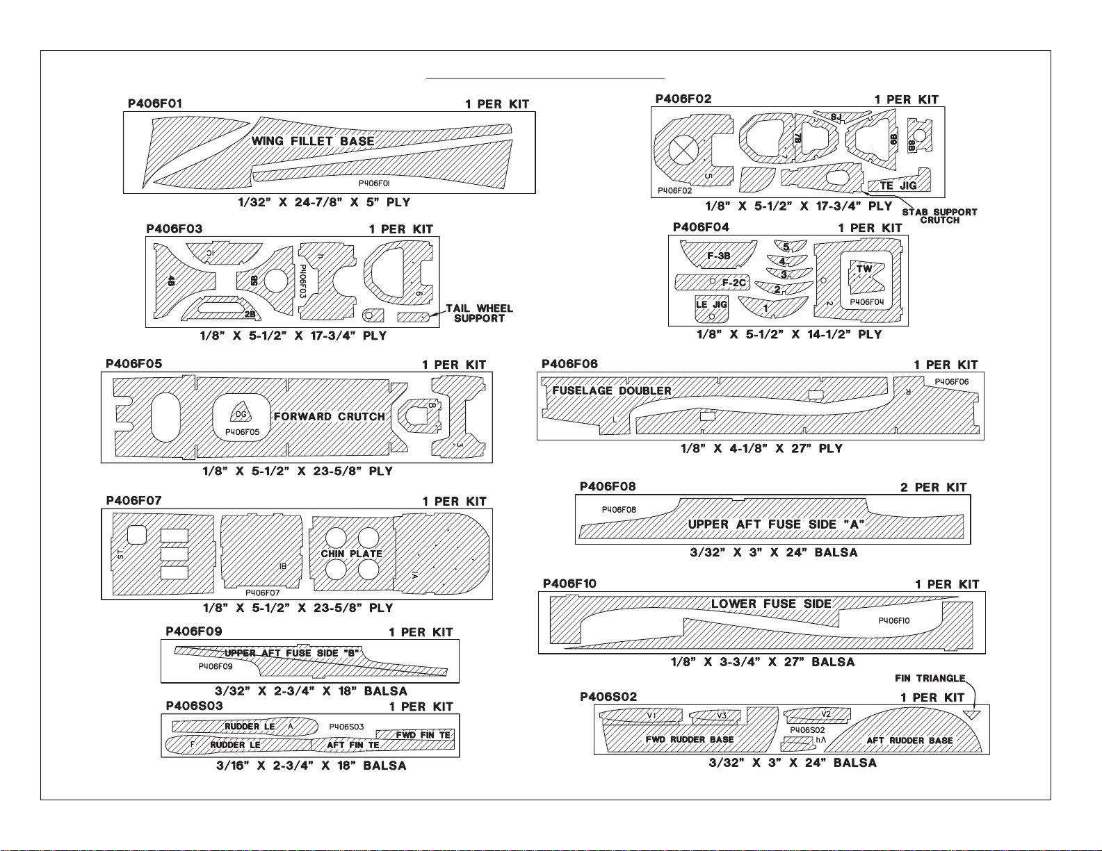
DIE-CUT PATTERNS
- 4 -
Page 5
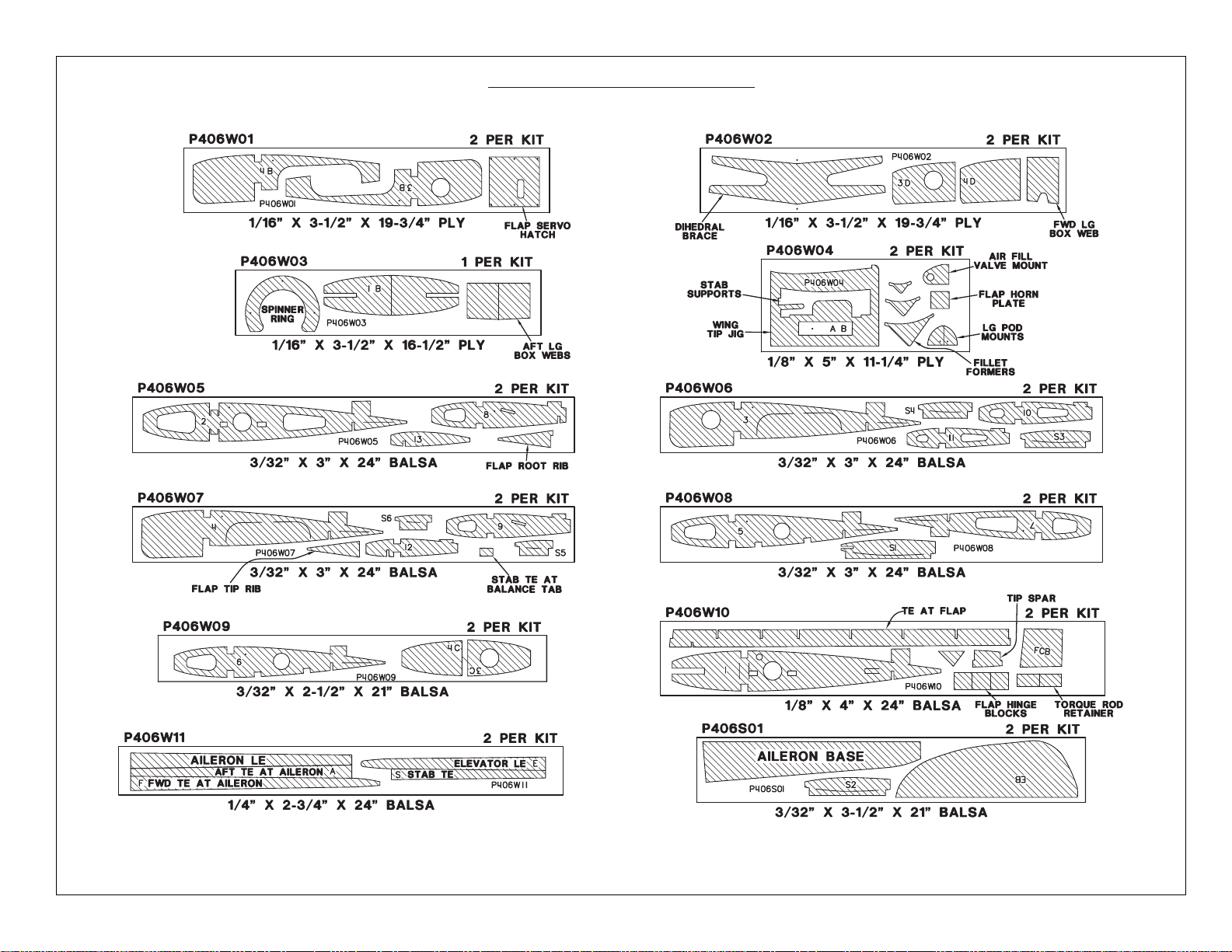
DIE-CUT PATTERNS
- 5 -
Page 6
Remember: Take your time and follow
directions to end up with a well-built model that
is straight and true.
DECISIONS Y
OU MUST
MAKE EARL
Y IN THE
BUILDING SEQUENCE
ENGINE AND MOUNT SELECTION
The recommended engine size range is as
follows:
.60 to .91 cu. in. 2-cycle
.90 to .120 cu. in. 4-cycle
The Warhawk will fly well with any of the
recommended engines. The 4-Cycle engines and
most .90 2-Cycle engines will turn a larger prop at
lower RPM’s. This is often desirable for scale
realism. Many .60 2-Cycle engines produce about
as much horsepower as the popular .90 2-Cycle
engines and will fly the Warhawk fine. If you use a
.60 2-Cycle, a Schnuerle ported engine is
preferred. The prototype P-40 with all of the
options, including flaps, retracts, drop tank, paint
etc., has been flown with an O.S. .61 SF. This
combination works fine and gives very realistic
scale power. Most modelers are accustomed to a
larger power reserve and would probably prefer
more power if they load up their P-40 with all of the
extras.
Even though the P-40 is designed to house the
engine inverted, a modeler desiring a more
utilitarian setup can mount his engine with the
cylinder head sticking out the right side of the
model. The same engine centerline should be
used.
The mount selection is up to you. If you use an
O.S. 1.20 4-cycle, the plans show (and the firewall
is spaced for) a J-tec No. JT-122 SV (JTEG8450).
The included mount will hold many 2-Cycle
engines such as the O.S. .61 SF.
A special muffler and header is available that
will fit inside your cowling. It is primarily designed
for 2-cycle engines mounted inverted.
*Header for O.S. .61SF (TOPQ7920)
*Header for SuperTigre S61K & S75K
(TOPQ7925)
*Muffler for above (TOPQ7915)
RETRACTS
The choice whether or not to use fixed gear or
retracts is up to you. Retracts offer good looks and
great flight realism with the added expense and
complication. The model is designed to use the
Robart #615 (ROBQ1815) rotating retracts, as
these offer the easiest installation and most
reliable operation. More information on retracts is
found in the “Tips for Competition Minded
Modelers” section and in the construction
sequence. For item numbers, see "Other Items
Required", page 7.
WHEEL SELECTION
The true scale tire size is 4-5/8”. The
recommended range of tire sizes is 3-1/4” to 4”.
The 4” wheels fit comfortably into the wing when
retracted. If you use fixed gear, you may choose
to use the smaller tires to reduce drag in the air.
Robart 4" (ROBQ1537) main wheels are very close
to scale appearance for a P-40. A 1-1/4” tail wheel
is scale and recommended.
FLAPS
This model is designed to incorporate split
flaps that are very scale. They are not difficult to
assemble, but they do require good craftsmanship
if they are to fit well. They add a good deal to the
model’s flight characteristics and scale appeal
while causing no bad effects. No trim correction of
any kind is needed when they are used with the
recommended throws. The flaps add drag and lift
to the model on landing approaches, which gives
the plane a very steady, locked-in feel. The flaps
require one channel, a Y-harness, and two
standard or mini servos. They are highly
recommended for those who wish to install them.
More information on the use of the flaps may be
found in the
Flying Section
.
DROP TANK
P-40s in combat used drop tanks most of the
time. Top Flite has made a correctly sized,
vacuum-formed drop tank available for your
warbird. The tank comes with a release
mechanism and is easy to assemble and install.
The drop tank will add a great deal of realism to
your Warhawk. Part #TOPQ7900
STATIC DISPLAY PROPELLER
When displaying your model, nothing adds
more realism than a good looking scale propeller.
Top Flite has a 3-bladed scale propeller available
for your P-40. Remember, this propeller is for
static display only; do not attempt to run the engine
with it mounted. Part # TOPQ7907
- 6 -
NOTE: We, as the kit manufacturer, can
provide you with a top quality kit and great
instructions, but ultimately the quality and
flyability of your finished model depends on
how you build it. Therefore, we cannot in any
way guarantee the performance of your
completed model, and no representations are
expressed or implied as to the performance or
safety of your completed model.
Page 7
SUGGESTED SUPPLIES AND TOOLS
We recommend only Top Flite Supreme™
glues for the assembly of our models.
❑
2 oz. CA [thin] (TOPR1003)
❑
2 oz. CA+ [thick] (TOPR1008)
❑
6-Minute Epoxy (TOPR1040)
❑
30-Minute Epoxy (TOPR1043)
❑
Hand or Electric Drill
❑
Drill Bits: 1/16”, 3/32”, 1/8”, 5/32”, 3/16”, 13/64”,
1/4”, 17/64”
❑
Sealing Iron (Top Flite) (TOPR2100)
❑
Heat Gun (Top Flite) (TOPR2000)
❑
Hobby Saw (X-acto Razor Saw)
❑
X-acto Knife, #11 Blades
❑
Pliers
❑
Screw Drivers
❑
T-Pins
❑
String
❑
Straightedge with length graduations
❑
Masking Tape (Required for construction)
❑
Sandpaper (coarse, medium, fine grit)*
❑
T-Bar Sanding Block (or similar)
❑
Waxed Paper
❑
Lightweight Balsa Filler such as Hobbico
®
HobbyLite™ (HCAR3400)
❑
1/4-20 Tap, Tap Wrench
❑
Isopropyl Rubbing Alcohol (70%)
❑
Dremel Moto Tool or similar (optional)
❑
Razor Plane
*NOTE: On our workbench, we have
four 11” T-Bar sanders, equipped with
#50, #80, #150 and #220-grit sandpaper.
This setup is all that is required for
almost any sanding task. Sanding
blocks can be made from balsa for
sanding hard to reach spots. We also
keep some #320-grit wet-or-dry
sandpaper handy for finish sanding
before covering.
COMMON ABBREVIATIONS USED IN
THIS BOOK AND ON THE PLANS:
deg. = Degrees
Elev = Elevator
Fuse = Fuselage
LE = Leading Edge (front)
LG = Landing Gear
Lt = Left
Ply = Plywood
Rt = Right
Stab = Stabilizer
TE = Trailing Edge (rear)
" = Inches
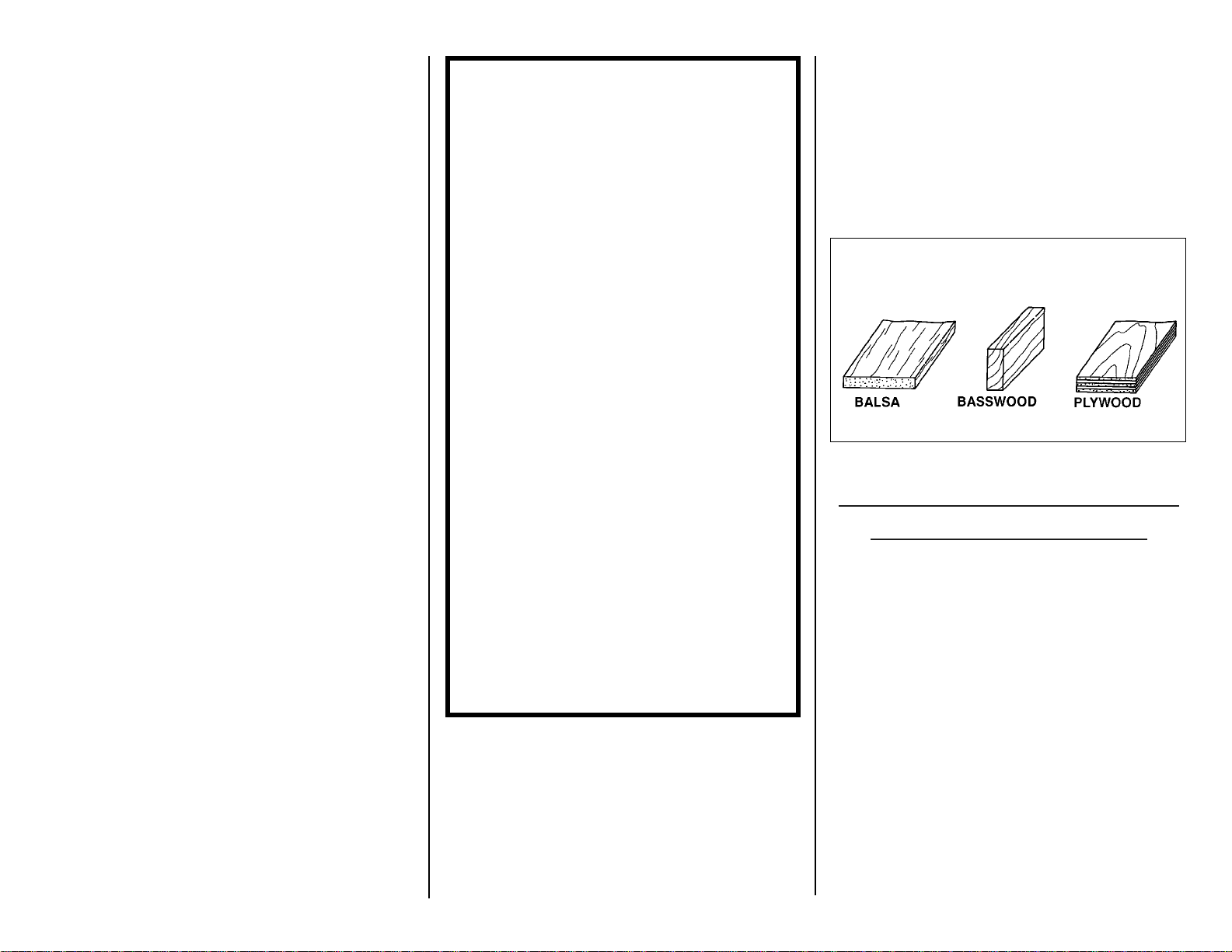
TYPES OF WOOD
TIPS FOR COMPETITION-
MINDED MODELERS
DEVIATIONS FROM SCALE
The rudder hinge line has been simplified to
allow you to use conventional model hinging
techniques. The elevator hinge line near the tip of
the stab was changed slightly to simplify the
elevator shape.
If you plan to compete with the trim scheme
shown on the box, here are a few things to
consider:
The full size P-40 that was duplicated is a
P-40E which was restored and is still in existence.
It matches the Koku Fan 3-view very well, with a
few exceptions.
- 7 -
OTHER ITEMS REQUIRED
❑
Four to seven channel radio with 4 to 8
servos.
❑
Engine (see page 6)
❑
Propellers (see engine instructions for
recommended sizes).
❑
Pilot figure (1/7thor 2” scale
recommended)
❑
4” P-40 Top Flite spinner
#TOPQ5401 red, #TOPQ5400 white
❑
Fuel Tank (Most 10 to 16 oz. tanks will fit)
❑
3-1/4” to 4” Main Wheels (2) (see page 6)
❑
1-1/4” Tail wheel
❑
3/16” Wheel Collars (4 for fixed gear main
wheels)
❑
3/32” Wheel Collars (2 for tail wheel)
❑
Top Flite Super MonoKote (2 rolls) Clear
(see
Finishing Section
)
❑
Paint (see
Finishing Section
)
❑
Silicone Fuel Tubing
❑
Latex Foam Rubber Padding (1/4” thick)
Optional:
❑
Drop Tank...............TOPQ7900
❑
Static Prop..............TOPQ7907
❑
Retracts ..................Robart #615
❑
Air Control Kit .........Robart #188
❑
Robostruts ..............Robart #650
❑
Engine Mount .........(see page 6)
Page 8
The most serious deviation is in the rear
portion of the canopy. The rear window recesses
(White ABS plastic in the model kit) were removed
from the full scale aircraft. This is presumably to
allow for a passenger. If you plan to enter serious
competition, you will probably want to modify your
kit to eliminate these panels. We chose to have
the kit build as a stock P-40E.
The P-40 was equipped with a variety of guns.
The guns in the photos differ from the ones on the
3-view. This is not a problem; just duplicate the
ones in the photos as we did on our prototypes
using 3/16” brass tubes.
Always work from the photos of the full size
aircraft and the proper 3-view drawing when
finishing your model because that is what you will
use for documentation.
SCALE RETRACTS AND DOORS
The retract landing gear pivot location shown
on the plans is correct. The stance of the model
(and strut length) shown with the gear down is
correct. Keep in mind that the Warhawk's gear,
like that in most modern aircraft, compresses
under the weight of the aircraft and extends when
the aircraft takes off. This fact means that the rigid
struts commonly used on models will not fold into
the scale locations. The normal way to deal with
this problem in models is to set up the model to
have the proper stance, and then have the wheel
retract into a position short of the scale location.
The only other reasonable way to overcome this
problem is to use oleo struts (such as Robart
Robostruts) that have springs light enough to
compress under the weight of the model and thus
function in a scale fashion.
The full scale P-40 uses landing gear doors on
the pods. We have not made these functional on
any of our models so we cannot offer any help on
implementing these.
GET READ
Y TO BUILD
NOTE: When you see "CA," use super
thin Supreme glue. When you see
"CA+," use thick Supreme glue.
❑
1. Unroll the plan sheets. Re-roll the plans
inside out to make them lie flat.
❑
2. Remove all parts from the box. As you do,
identify the name of each part by comparing it with
the plans and the parts list at the back of this book.
Using a felt tip or ball point pen, write the part
name or size on each piece to avoid confusion
later. Use the die-cut patterns shown on pages 4
and 5 to identify the die-cut parts and mark them
before punching out. Save all scraps. If any of
the die-cut parts are difficult to punch out, do not
force them! Instead, first cut around the parts with
a sharp hobby knife. After punching out the die-cut
parts, use your T-Bar or sanding block to lightly
sand the edges to remove any die-cutting
irregularities.
❑
3. As you identify and mark the parts, separate
them into groups, such as fuse (fuselage), wing,
fin and stab (stabilizer), and hardware.
BUILD THE HORIZONTAL STABILIZER
❑
1. Work on a flat surface over the plans
covered with waxed paper. Refer to the plans to
identify the parts and their locations.
❑
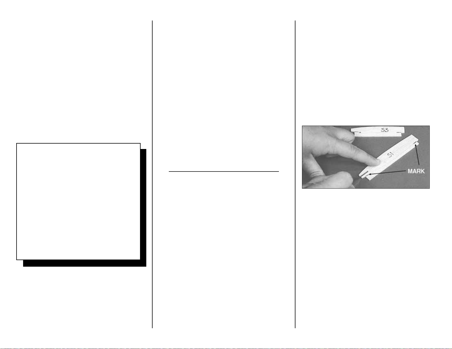
2. Punch out both sets of the die-cut 3/32”
balsa ribs S-1 to S-6. There is a jig tab on the
bottom edge of each of these ribs. If any of these
break off, carefully glue them back on with CA.
Lightly sand any imperfections. You may need to
finish cutting the notch in the forward portion of S-1
for the Stab Joiner (SJ) with a knife. Use a pen to
mark the extensions of the bottom edge of the ribs
across the fore and aft ends of the jig tabs. These
will help you when you trim off the jig tabs later.
❑
3. The stab Trailing Edges (S) are die-cut
from 1/4” balsa. Since some crushing may happen
when die-cutting wood of this thickness, they are
supplied slightly long and can be trimmed. True up
the ends of these pieces with sandpaper. Also
true up the top and bottom edges of these pieces
with a T-bar.
- 8 -
SCALE DOCUMENTATION
This model was designed using the Koku-Fan
3-view drawings as the reference for outline.
This fact makes it preferable to use those
drawings for scale documentation. The
drawings and many Warhawk photo packs are
available from:
Scale Model Research
3114 Yukon Ave
Costa Mesa, CA 92626
(714) 979-8058
The trim scheme shown on the box is from
photo pack #588 (54 pictures $35) -or- #588a
(16 pictures $16) +$3 S&H
Page 9
❑
4. The stab and fin Leading Edges (LE’s) are
cut to length from the 1/4” x 30” tapered
balsa stock. Cut two pieces about 1/4”
longer than the length shown on the plans
for the stab LE.
HINT: Bevel the front edge of the stab
and fin ribs to match the sweep angle of
the LE stock. This will give you a better
fit and a stronger glue joint.
❑❑
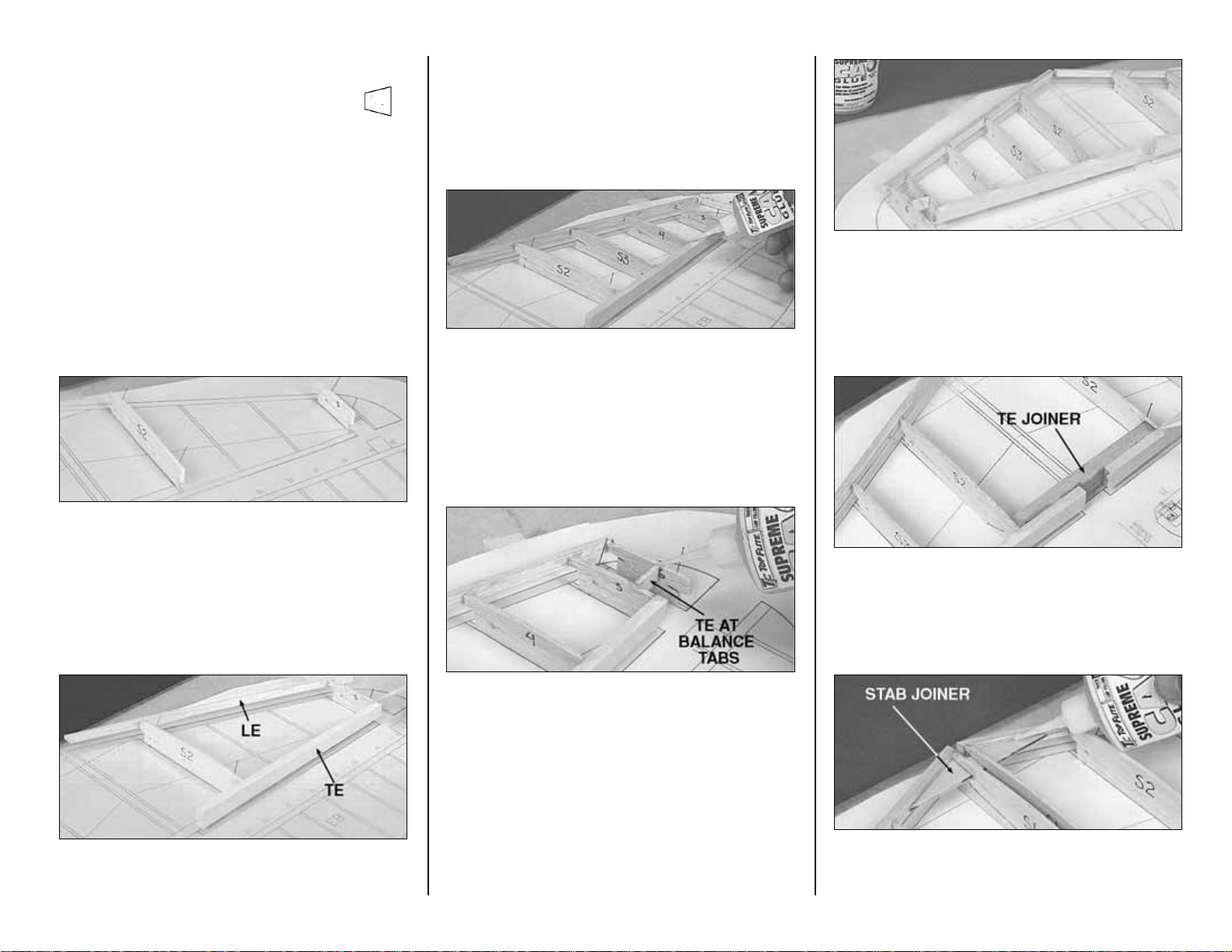
5. Starting with the right half of the stab,
pin ribs S-2 and S-5 to the building board over their
locations on the plans.
❑❑
6. Center the LE vertically on the front
edge of ribs S-2 and S-5. Glue it in place with CA.
❑❑
7. Center the TE vertically on the back
edge of ribs S-2 and S-5. Glue it in place with CA.
❑❑
8. Glue ribs S-3 and S-4 in their places.
All of the jig tabs should rest on the work surface.
❑❑
9. Glue rib S-6 to the LE. Glue the die-cut
3/32” balsa TE at Balance Tab between ribs S-5
and S-6 at the location shown on the plans.
❑❑
10. Trim the LE and TE near the stab
center so they match the endpoints shown on the
plans.
❑
11. Repeat steps 5 through 10 to build the left
half of the stab. The left half of the stab is built
beside the right half and the two halves do not
touch for now.
❑
12. Trim the 3/8” x 9/16” x 4-1/2" hard balsa
stab TE Joiner, if necessary, to fit between the
S-2’s. Securely glue it to the stab TE’s and the
S-2’s using CA.
❑
13. Check the fit of the die-cut 1/8” plywood
Stab Joiner (SJ) and adjust if required for a good
- 9 -
Page 10
- 10 -
fit to the stab LE’s. Place the Stab Joiner into the
slots in the two S-1’s and work the whole assembly
into position. Make sure all parts are properly
aligned and the S-1 rib jig tabs contact the work
surface. Glue in the Stab Joiner and the S-1’s
using CA.
❑
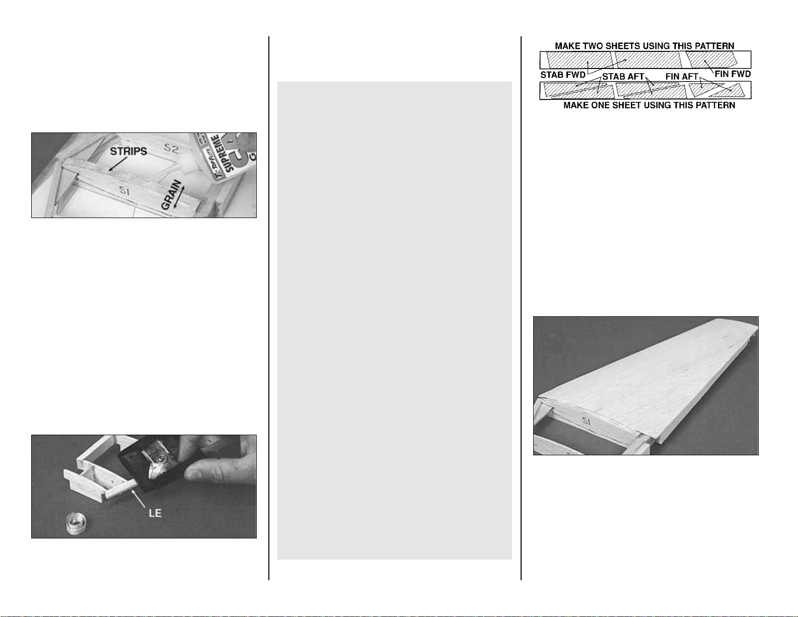
14. Cut two 1/4” wide cross grain strips off the
end of a 1/16” x 3” x 30” wing sheet. Glue these
strips between the two S-1 ribs flush with their top
edges. These strips will reinforce the stab skins
where they join at the center and strengthen the
stab.
❑
15. Use CA+ to reinforce any glue joints that
do not look strong.
❑
16. Carefully remove the stab from the
building board but try not to damage the jig tabs,
as they will be useful until after the top of the stab
is sheeted.
❑
17. Use a razor plane and a sanding block to
cut down the top surface of the LE (particularly
toward the tip) until it is even with the ribs. Sand
the TE, if required, to have a smooth transition
from the ribs.
TIPS FOR MAKING WING AND STAB
SKINS
A. Wherever practical, pre-join the balsa sheets to
make a “skin” before attaching them to the
structure.
B. Many modelers like to sort the wood so they
can put the best wood with the most even grain
structure on the top of the wing and stab.
C. Make your skin larger than needed to allow for
misalignment. On a large surface like the wing,
3/8” extra is suggested.
D. To make skins the following steps are
recommended:
1. True up the edges of the sheets with a
metal straight edge and a sharp knife or a “T-Bar”
sanding block.
2. Test fit the sheets together to make sure
they match well.
3. Glue the sheets together with CA over a flat
surface covered with waxed paper. A quick wipe
of the joint with a fresh paper towel will remove
excess glue and make sanding easier. Mark the
poorest surface that you think should be the inside
of the sheet with an “I”.
4. Place the skin on a large flat surface and
sand it with a large flat sanding block and fresh,
sharp 220 paper.
5. Trim the perimeter of the sheet to even
things out.
❑
18. Make four stab skins from three 1/16” x 3”
x 30” balsa wing sheet pieces. See the sketch for
the proper layout on the wood. Refer to the plans
for the exact shapes and sizes, but remember to
make the skins slightly oversize.
❑
19. Pin the stab structure onto the flat building
surface. Test fit the skins over the structure. Make
sure the skins meet well at the center. Adjust them
if necessary.
❑
20. Apply an even bead of CA+to the upward
facing edges of the structure. Place the skin in its
proper position and press it firmly down until the
glue has set. Take your time here as a strong joint
is critical. Repeat this step for the other top skin.
❑
21. Remove the stab from the building board.
Trim off the jig tabs with a sharp knife. Trim and
Page 11
blend the LE and TE to the ribs as you did before
and sand the bottom edges of the ribs lightly with a
T-bar sander. Check all glue joints, adding glue as
necessary
❑
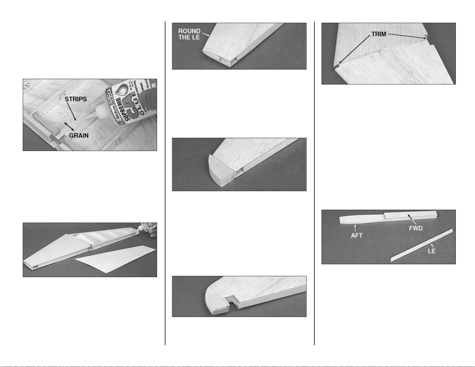
22. Cut two 1/4” wide strips off the end of a
1/16” x 3” x 30” wing sheet. Glue these strips
between the two S-1 ribs flush with their bottom
edges.
❑
23. It is important to get a good glue bond
between the stab structure and the bottom stab
skins. Apply a heavy bead of CA+to all of the
upward facing edges of one side of the stab
structure. Place a skin on the structure and hold it
in place with your hands until the glue sets.
Repeat this for the other bottom skin. Be careful
not to bend or twist the stab during this step.
❑
24. True up the ends of the stab with a
sanding block. Round the leading edge of the stab
to match the cross section on the plan.
❑
25. Glue on the 5/8” thick shaped balsa Stab
Tips. Use a razor plane and a sanding block to
airfoil them to match the stab. You may contour
the tip to its final shape now, or wait until the model
is nearer completion.
❑
26. Cut away the skin in the area of the
balance tabs. True up the skin with a T-bar.
❑
27. Cut away the skin at the center of the stab
at the LE and TE as shown in the photo
BUILD THE FIN
❑
1. Cut a 6-5/8” length of the tapered 1/4” balsa
stabilizer LE stock. Notice that the fin LE protrudes
through the stab.
❑
2. Glue the die-cut 3/16” balsa Fwd and Aft
Fin TE’s together with CA. Since these pieces are
thick and die-cut, they will probably require a little
touch up and blending with a sanding block.
❑
3. Punch out the die-cut 3/32” balsa ribs V-1
through V-4. Be sure to preserve their jig tabs.
- 11 -
Page 12
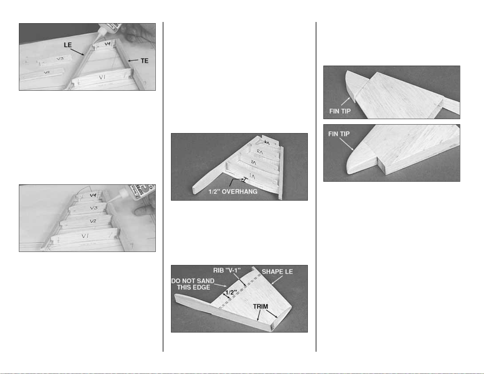
❑
4. Pin ribs V-1 and V-4 to the building board
over their proper locations. Center the LE
vertically on the front of the ribs and glue it in
place.
❑
5. Center the Fin TE vertically on the aft edge
of the ribs and glue it in place.
❑
6. Put ribs V-2 and V-3 into their places and
glue them. Remember, all jig tabs should contact
the work surface.
❑
7. Glue the die-cut 3/32” balsa Fin Triangle
into the corner of V-4 and the Trailing Edge.
❑
8. Apply extra CA+ glue to any joints that do
not appear to be well glued.
❑
9. Blend the LE to match the ribs on the
upward facing (left) fin side. Sand the TE, if
necessary, to blend smoothly with the ribs.
❑
10. Make a skin for each side of the fin using
the 1/16” balsa sheet left over from the stab skins.
Make the skin so it overhangs past V-1 about 1/2”;
this will allow fitting to the stab later. See the
sketch on page 11.
❑
11. With the structure flat on the table, glue on
the left skin.
❑
12. Trim off the jig tabs and blend the LE and
TE to the ribs on the right side of the fin.
❑
13. Glue on the right skin. Be sure to get a
good bond between the ribs and the skin.
❑
14. True up the edges of the fin sheeting with
a sanding block. Shape the LE to match the crosssection on the plans.
❑
15. Glue the shaped 3/4” balsa Fin Tip to the
top of the fin at the location shown on the plans.
Use a razor plane and a sanding block to do the
initial shaping of the tip. Final shaping should be
done later, with the fin taped to the rudder.
BUILD THE ELEVATORS
NOTE: Build both elevators using the
following steps:
❑❑
1. Place the die-cut 3/32” balsa Elevator
Bases (EB) on the plans and mark the “Rib”
locations on both sides using the “tick” marks on
the plans.
- 12 -
Page 13
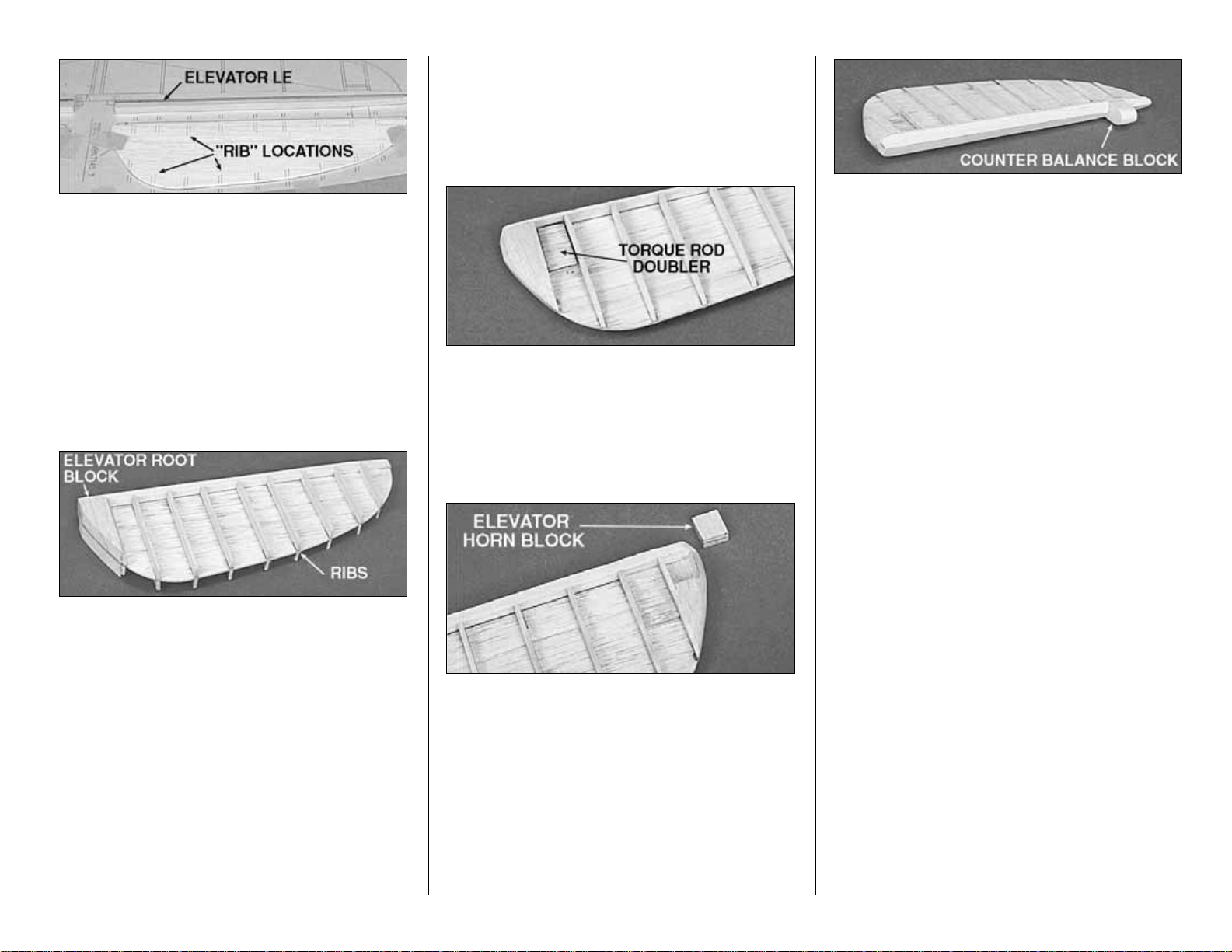
❑❑
2. Draw a centerline on both surfaces of
the die-cut 1/4” balsa Elevator LE (E). Draw two
parallel lines 1/16” away from center line on the aft
side.
❑❑
3. Hold the Elevator Base centered
between the lines on the Elevator LE. Use CA to
glue the Elevator Base to the LE.
❑❑
4. Cut “ribs” from the 3/32” x 3/8” x 36”
balsa sticks and glue them onto both sides of the
elevator base at the locations you previously
marked.
❑❑
5. Glue a 3/8” thick shaped balsa
Elevator Root block to each side of the Elevator
Base.
❑❑
6. Refer to the photos on this page and the
cross-sections on the plans to obtain the shape of
the elevators. Use a razor plane and sanding
block to “rough in” the shape of the elevators. Trial
fit the elevators to the stab for final shaping.
❑❑
7. Glue a die-cut 1/8” balsa elevator
Torque Rod Doubler to both sides of the Elevator
Base as shown on the plans.
❑❑
8. Cut a pocket in the bottom of the right
elevator to match the 1/4” x 1/2” x 5/8” Elevator
Horn Block. Check the plans for the proper
location.
❑❑
9. Glue, using 6-minute epoxy, the birch
plywood Elevator Horn Block in the pocket on the
bottom side of the right elevator. Shape the
Elevator Horn Block edge to match the elevator.
❑❑
10. Place the elevator over the plans and
mark position of the 5/8” x 5/8” x 11/16” balsa
Counter Balance Block on the elevator LE. Glue
the Counter Balance Block in place. Shape the
front of the block to a full radius. Allow
approximately 1/16” clearance on both sides of the
counter balance block in the stab opening.
❑❑
11. Shape the Elevator LE to a “V”
shape to allow elevator travel. See the crosssection on the plans for the correct shape.
❑❑
12. Tape the elevators to the stabilizer.
Hold the bent 1/8” Elevator Joiner Wire up to the
elevator and mark the location of the holes (see
the plans for the joiner location).
❑❑
13. Remove the elevators from the
stabilizer. Drill 1/8” holes in the elevators for the
Joiner wire. Make slots inboard of the holes to
allow the wire to be inset into the elevators.
❑❑
14. Test fit the joiner wire into the
elevators. Check to see if the elevators align with
each other properly. Make adjustments if required.
BUILD THE RUDDER
❑
1. Glue the two die-cut 3/16” balsa Rudder
LE’s together with CA+. Even up the edges with a
sanding block, but save any tapering for later.
- 13 -
Page 14
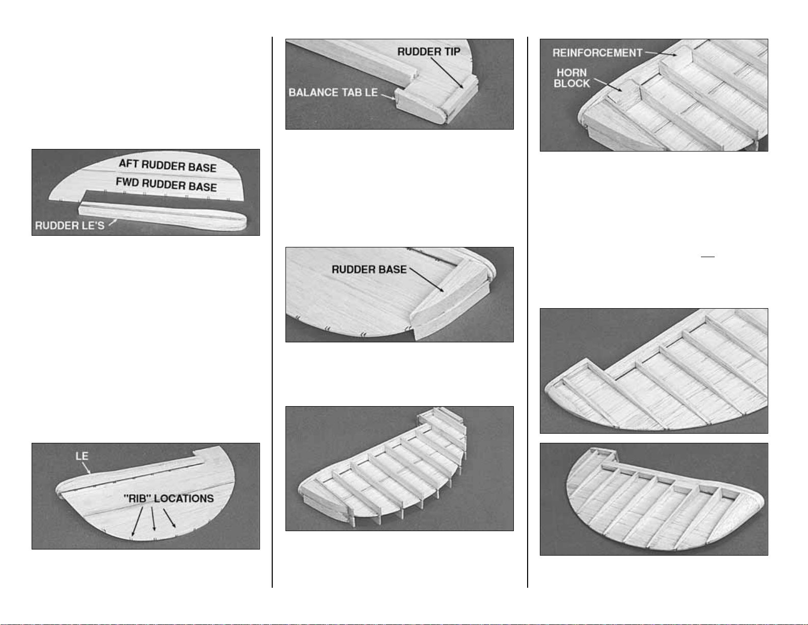
❑
2. Draw a centerline on the aft surface of the
LE. Draw two parallel lines 1/16” away on both
sides of the centerline.
❑
3. Glue the die-cut 3/32” balsa FWD Rudder
Base to the die-cut 3/32” balsa AFT Rudder Base.
❑
4. Align the Rudder Base over the plans and
mark the “Rib” locations on both sides of the
Rudder Base.
❑
5. Hold the Rudder Base centered on the
rudder LE. Apply CA to the joint.
❑❑
6. Center the 1/4” x 3/4” x 2” balsa rudder
Balance Tab LE on the top of the rudder plate.
Glue it with CA.
❑❑
7. Glue a 1/4” x 1/4” x 1-3/4 stick balsa
Rudder Tip to each side of the top of the rudder
plate.
❑❑
8. Glue a 1/2” thick shaped balsa Rudder
Base to each side of the bottom of the rudder
plate.
❑❑
9. Cut “ribs” from the 3/32” x 1/2” x 36”
balsa sticks and glue them onto both sides of the
rudder at the locations you previously marked.
❑❑
10. Glue the a 3/8” x 1/2” x 1-1/16” balsa
Rudder Reinforcement Stick to each side of the
rudder at the location shown on the plans. These
will strengthen the rudder when the slot to clear the
elevator joiner wire is cut out.
❑❑
11. Glue the 1/2 x 5/8” x 15/16” hard
balsa Rudder Horn Block to the left side of the
rudder where it is shown on the plans.
❑❑
12. Refer to the photos and the cross-
- 14 -
Page 15
sections on the plans to obtain the shape of the
rudder. Use a razor plane and sanding block to
“rough in” the shape of the rudder. Final shaping
and fitting should be done after the fin is glued
onto the fuselage, but you may wish to tape the
rudder to the fin at this point to blend the upper
ends of both.
BUILD THE WING
NOTE: The wing halves are built
“UPSIDE-DOWN” on the plans. The jig
tabs are attached to what is, in the end,
the TOP surface of the wing.
NOTE: Since it is the standard
convention to show the Top View of the
wing, and the wing panels are built
upside-down, the LEFT wing panel is
built over the RIGHT Wing Top View
and vice-versa. This does not present
any problems; just be sure to build a
left and a right wing panel.
❑
1. Place the wing plan on your building board
and cover it with waxed paper (you may wish to cut
apart the wing panel sections of the plan to make
handling easier.)
❑
2. Hold the four 1/4” x 3/8” x 36” hard balsa
Spars over the wing plans. Mark the spars about
1/4” longer than they need to be. Cut off the spars
at the marks and save the scraps for the flap and
aileron servo mounts.
❑
3. Punch out all the die-cut 3/32” balsa wing
Ribs. Smooth out any imperfections with
sandpaper. Be sure to keep the jig tabs attached
to the ribs.
❑
4. Ribs W-1 through W-8 have punch marks
just aft of the spar that locate the aileron pushrods
for you. Drill a 3/16” hole at each of these marks.
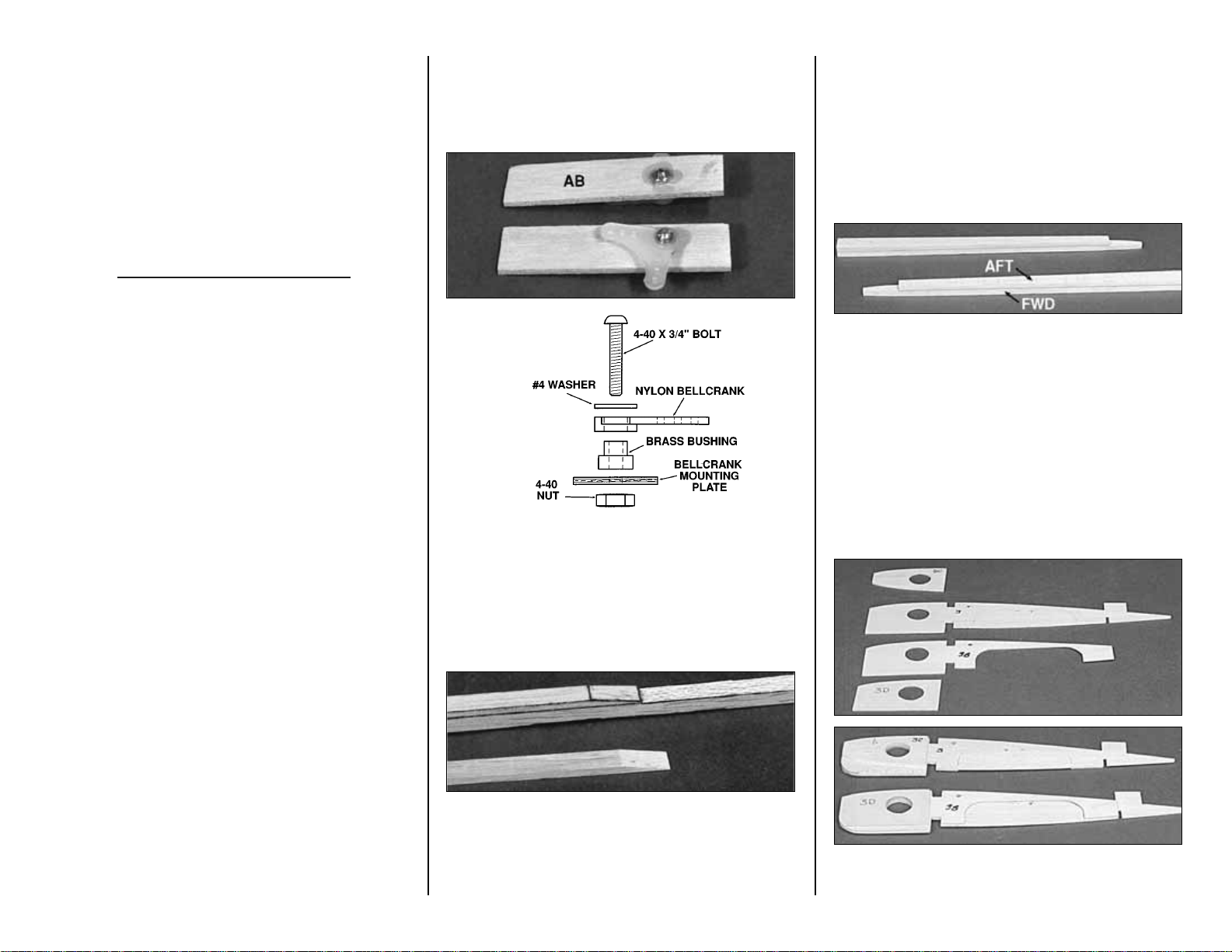
❑
5. Drill 1/8” holes through the punch marks in
the two die-cut 1/8” plywood Aileron Bellcrank
Plates (AB). Assemble the bellcrank parts as
shown in the sketch. Be sure to put a drop of
6-minute epoxy on the 4-40 nut and threads to
prevent the bellcrank from vibrating loose.
❑
6. Taper one end of each of the four 1/8” x 3/8”
x 17-1/2” balsa Spar Doublers to match the spar
detail drawing on the plans. Glue a Spar Doubler
to each Spar with the root (non-tapered) end of the
doubler aligned with the root end of the spar.
NOTE: The top edge of the FWD
TRAILING EDGE AT AILERON curves
more than the bottom edge at the tip.
Since the wing is being built upside
down, the more curved edge faces
down next to the plans.
❑
7. Center the die-cut 1/4” balsa Aft Trailing
Edge at Aileron (A) on the die-cut 1/4” balsa
Forward Trailing Edge at Aileron (F) and glue
them together with CA. Be sure to make a left
and a right trailing edge. Use a sanding block to
taper the two pieces slightly as shown in the crosssectional drawing on the plan. These pieces are
die-cut slightly long to allow you to trim off any
imperfections.
❑
8. Each of the W-4 and W-3 ribs is made up of
four laminations. Refer to the plans for the proper
- 15 -
Page 16
order of the parts (e.g. 4C, 4, 4B, 4D.) Use CA+ to
glue the parts together. Be sure to make a left
and a right of each rib assembly.
❑
9. Enlarge the pushrod hole in each W-8 until
it is a 5/16” x 5/16” square hole. This will provide
clearance for the clevis.
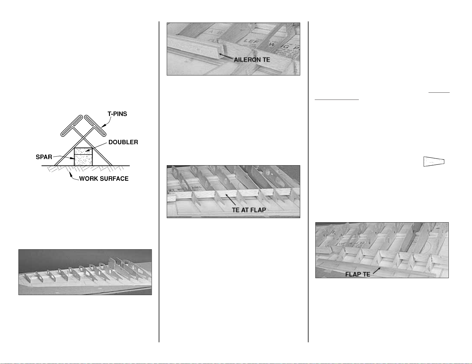
❑❑
10. Pin a Spar assembly to the building
board at three or four locations using the crosspinning technique shown in the sketch.
❑❑
11. Glue the die-cut 3/32” balsa ribs W-2
through W-12 to the spar. These should be
vertical and aligned over their appropriate locations
as indicated on the plans. The jig tabs located
near the aft end of the ribs should all contact the
work surface.
❑❑
12. Glue the aileron trailing edge
assembly to the aft edge of ribs W-8 through W-12.
The upward facing edges of the ribs and the top
surface of the trailing edge should be even, and all
of the jig tabs should touch the work surface.
NOTE: The inboard end of the aileron TE extends
approximately 5/8” inboard of rib W-8, as shown on
the plan.
❑❑
13. Test fit the die-cut 1/8” balsa TE At
Flap to the wing ribs. You will probably have to
angle the notches with your hobby knife to match
the forward sweep of the trailing edge. Place the
TE At Flap back into the wing rib structure but do
not glue yet.
❑❑
14. Sight down the TE of the wing from
the root end; make sure all the ribs are aligned at
the same height. Use paper to shim under the jig
tabs of any ribs that are low. This will put the TE’s
of the ribs in line.
❑❑
15. When the TE At Flap is fitting in place
well, with all of the rib TE’s aligned, glue it in with
CA+.
NOTE: Do steps 16 and 17 for a plane without
operating flaps. Skip these steps for a plane
with operational flaps.
❑❑
16. Cut the ends of the tapered 1/2" x 19”
balsa Flap TE about 1/8” longer than it
is shown on the plan. Note: This Flap
TE is not used if you build operating
flaps.
❑❑
17. Glue the Flap TE to ribs W-2 and W-7.
The Flap TE should be centered vertically on the
aft edges of the ribs and should be symmetrically
aligned with the top and bottom of the ribs. Make
sure all the jig tabs are contacting the work
surface. A metal straightedge can be placed on
the structure over the jig tabs to hold them down
evenly.
- 16 -
Page 17
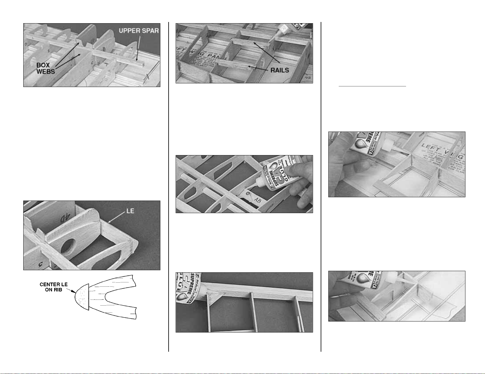
❑❑
18. Work the Upper Spar assembly into
place, making sure it fits well. Put some weights
on top of the structure to make sure it is held onto
the work surface. Fit the die-cut 1/16” plywood
Fwd and Aft LG Box Webs between W-3 and W-4
to confirm the angle of these ribs. Use CA to glue
in the top spar. Thoroughly glue the Fwd and Aft
LG Box Webs to the spars as well as W-3 and
W-4.
❑❑
19. Hold the shaped balsa Leading Edge
centered vertically on the front edge of the ribs.
Use CA to glue it in place.
❑❑
20. If you are going to use flaps, trim the
1/4” x 3/8” balsa stock left over from the wing spars
to the length shown on the plans for the Flap Bay
Rails. Glue the rails into the notches in W-5 and
W-6 with CA. If you do not plan to use flaps, you
should fill the notches with scrap wood.
❑❑
21. Glue the aileron bellcrank assembly
into the slots in ribs W-8 and W-9. The bellcrank
should face away from the building board as
shown in the photo.
❑❑
22. Glue the die-cut 1/8” balsa Corner
Brace into the corner of W-8 and the Trailing
Edge.
Note: Do steps 23 and 24 for a plane
without operating flaps. Skip them for a
plane with operating flaps.
❑❑
23. Test fit, then glue in the die-cut 3/32”
balsa Flap Tip Rib at the location shown on the
plans.
❑❑
24. Glue in the die-cut 3/32” balsa Flap
Root Rib.
- 17 -
Page 18

❑❑
25. Trim the 1/16” balsa Shear Webs to fit
behind the spar between ribs W-4 through W-12.
Glue them in place with CA+. Wick CA- into all the
joints of the Shear Webs and the Spars to make
sure they are well bonded. It is not important to
glue the shear webs to the ribs.
❑❑
26. Cut a 13” length of Outer Pushrod
Tube. Rough up the outside of the tube with 220
grit sandpaper. Feed the tube through the holes in
the ribs as shown on the plans. Use CA to glue
the tube in place.
❑❑
27. Cut three lengths of Inner Pushrod
Tube about 5/16” long and slide them onto a .074"
x 36" threaded one end wire, at the intervals
shown on the plans. Carefully apply a small drop
of CA to secure each short tube if they are not very
snug on the wire.
❑❑
28. Snap a Nylon Clevis with Clevis
Retainer securely onto the
bellcrank. Feed the wire
assembly into the wing and
screw the threaded end
well into the clevis. Hint: The
wire is extra long. After the
threaded end starts threading
into the clevis, you may bend over the excess wire
and use it as a handle to turn the wire the rest of
the way into the clevis. Be sure to hold the clevis
securely with pliers while threading the wire into it
to keep from stressing the clevis pin. Cut off the
excess wire about 1-1/4” beyond the root end of
the spar.
INSTALL THE CENTER RIB (W-1)
❑❑
29. Finish cutting the slot in the aft part of
the two W-1 ribs for the Wing Bolt Plate.
❑❑
30. Glue the die-cut 1/16” ply W-1B
doubler ribs to the W-1’s. Be sure to make a left
and a right.
❑❑
31. Glue the die-cut 1/8” balsa Fwd
Center Brace (FCB) to rib W-2 over its location on
the plans.
❑❑
32. Place rib W-1 into position. Glue it in
place with CA+. NOTE: FCB sets W-1 at the
correct angle.
- 18 -
Page 19

❑❑
33. Glue the 3/8” x 1-3/16” x 2-1/2” balsa
Center LE Block to the front of W-1 and the LE.
Cut a V-notch in the Center LE Block centered on
the dowel notch in W-1. This notch will assist you
in drilling for the dowel later.
❑❑
34. Insert the 1/4” x 3/8” balsa Servo
Mount Rails (left over from the wing spars) into
the slots in W-1 and W-2. Adjust the aft rail's
position to allow the servo you will use to fit
comfortably. Glue the rails in place.
❑❑
35. Trim the spars, the servo mounts, and
the LE Block flush with W-1.
INSTALL THE CENTER TE BLOCK
Do steps 1 and 2 if you are NOT building
operating flaps.
❑❑
1. Glue the 3/8” x 1/2” x 1-1/4” Center TE
Block to the TE of rib W-1 and the Flap TE.
❑❑
2. Trim off the end of the Center TE Block
flush with W-1. The block should be shaped after
the wing is joined and sheeted.
PREPARE THE WING PANELS
FOR THE FLAPS
Do steps 1 through 14 if you are building
operating flaps.
❑❑
1. Remove the wing panel from the
building board. Use a T-bar with fresh 220 grit
sandpaper to blend away any unevenness from
the structure. Pay special attention to the trailing
edge of the wing. It is important to make the
trailing edge as straight as possible so the split
flaps will fit well.
❑❑
2. Draw a centerline down the 1/16” x 1” x
19” plywood TE Strip.
❑❑
3. Use a T-bar with sharp 150 or 220 grit
paper to bevel the aft 3/8” of the TE Strip. This will
allow the TE to be only 3/32” thick when the flaps
are shut. See the cross-section on the plans for
the correct thickness and angle.
❑❑
4. Locate the two 3/32” x 5/8” x 18” balsa
TE Jig Strips. Check the straightness of these
jigs by holding them up on edge on a flat table.
True them up with a knife and a metal straight
edge if required.
- 19 -
Page 20

❑❑
5. Place the TE Strip with the beveled
and centerline-marked side down on a very flat
table. Glue a TE Jig Strip to the TE Strip. The jig
strip will keep the TE straight until the wing is
complete. Do not use excessive glue because it
will have to be sanded off later.
❑❑
6. Glue the TE assembly to the wing
structure. The aft end of ribs W-2 through W-7
should align with the centerline you drew on the TE
Strip. Do not force the ribs to touch the TE Strip.
This will cause the TE to warp when you remove
the Jig later; just fill any slight gaps with glue.
❑❑
7. Cut the die-cut 3/32” balsa Flap Tip
Rib in half along its centerline. Align half of the rib
over the plans and glue it in as shown in the photo.
❑❑
8. Align the die-cut 3/32” balsa Flap Root
Rib over its location on the plan and glue it in with
CA+.
❑❑
9. Trim off the ends of the TE Strip flush
with the W-1 rib and the Flap Tip Rib.
❑❑
10. Use a razor saw and a single edge
razor blade to trim off the bottom half of ribs W-2
to W-7 (behind the TE at Flap). The bottom side
is the side opposite the jig tabs.
❑❑
11. Use a T-bar sander to even up the ribs
inside the flap bay.
- 20 -
Page 21

❑❑
12. Cut the 5/8" X 5/8" X 6" balsa stick
into six equal blocks. Fit and glue these Flap
Hinge Blocks in place where shown on the wing
plan.
❑❑
13 Mark the locations of the hinge blocks
on the TE to help you find them later.
❑❑
14. Decide how you want to route the flap
servo extension wires. You will need to go through
or around the wheel well. Add passageways for
the extension in W-3 and W-4 if needed.
NOTE: Actual flap construction will
begin on page 27.
Repeat the previous wing sections (starting on
page 16) to build the other wing panel. Use the
other half of the wing plan, and remember to
build a right and a left wing panel.
JOIN THE WING PANELS
❑
1. Trim the ends of the spars and LE’s of both
panels even with rib W-12. Excess overhang will
affect the dihedral angle.
❑
2. Cut away the portion of rib W-1 around the
spars as shown in the photo. This will allow the
dihedral braces to pass through.
❑
3. Test fit the die-cut 1/16” plywood Dihedral
Braces into each wing half. Make sure the Brace
centerline can go all the way to the wing centerline.
Trim the ends of the Braces slightly, if required.
❑
4. Trim the jig tabs off all of the wing ribs
except W-1 and W-12. Use a T-bar to blend the
airfoil where the jig tabs were removed.
❑
5. Drill two 1/4” holes in the shaped 1/4”
plywood Wing Bolt Plate at the locations shown
on the wing plan.
❑
6. Test fit the 1/4” plywood Wing Bolt Plate
into each wing panel. Make adjustments, if
necessary, until the Wing Bolt Plate fits well.
❑
7. Assemble the two wing halves, the two
Dihedral Braces, and the Wing Bolt Plate together.
- 21 -
Page 22

Place the 3/8” x 2-5/8” x 10” balsa Wing Jig Block
under W-1. The W-1 jig tabs and the spar at W-1
should contact the Wing Jig Block. The W-12 jig
tabs and the spar at W-12 should contact your flat
work table.
❑
8. When you have confirmed that all of the
parts fit well, disassemble the wing parts. Coat the
inside of the Dihedral braces and the area of the
Spars that they contact with a thin film of 30-minute
epoxy. Reassemble the wing parts onto the jig
block. Align the two W-1 ribs with each other and
glue them together with CA. Make sure the wing is
properly jigged. Clamp the Dihedral braces to the
Spars with clamps or masking tape.
❑
9. Apply a fillet of 30-minute epoxy around the
Wing Bolt Plate.
❑
10. Use 30-minute epoxy to fill any gaps
where the Spars join in the middle.
❑
11. Drill a 3/16” pilot hole through the wing LE
for the 5/16" Wing Dowel. Gradually enlarge the
hole to 5/16” keeping the drill centered on the two
W-1 ribs.
❑
12. Make a 1/16” balsa shear web to fit
between W-2 and W-3. Glue it to the Dihedral
Brace on the aft side of the spar.
❑
13. Make the aileron pushrods from the 4”
threaded end rod. Use a Nylon
Clevis with a Clevis Retainer on
the horn end and a Z-bend on
the Bellcrank end. Make them
the length shown on the wing
plan top view.
❑
14. Drill out the outer hole in the bellcranks
with a 5/64” drill bit. Test fit the pushrod into the
bellcrank.
FIXED LANDING GEAR ASSEMBLY
Do the following six steps to make a left and a
right fixed gear assembly.
NOTE: The fixed gear is slightly shorter
than scale to improve ground handling.
❑❑
1. Use 30-minute epoxy to glue the 3/4” x
5/8” x 1” hardwood Landing Gear Block to one
end of the slotted 1/2” x 3/4” x 2-3/4” hardwood
Landing Gear Rail as shown on the plan and in
the photo.
❑❑
2. Locate the 1/8” x 1-11/16” x 2-3/4” birch
plywood Landing Gear Plate. Use the template
provided on the wing plan to mark the hole
locations. Drill the holes to the sizes indicated on
the template.
- 22 -
Page 23

❑❑
3. Test fit the bent Landing Gear wire
through the Landing Gear Plate. Chamfer the hole
in the plate for the wire, if required, until the wire
will lie fairly flat on the plate.
❑❑
4. Hold the Landing Gear Rail assembly
up to the Landing Gear Plate and wire. Mark the
location where the wire will insert into the Landing
Gear Rail.
❑❑
5. Drill the Landing Gear Rail assembly
with a 3/16” drill. Test fit the parts together and
chamfer the hole entries as required for a good fit.
Note: Small gaps will be pulled together when the
parts are screwed together.
❑❑
6. Mark the locations for the #4 screws.
Drill 3/32” pilot holes at the locations you marked.
Screw the parts together with #4 x 1/2” Sheet
Metal Screws.
MOUNT THE LANDING GEAR
Do the following eight steps for Retract and
Fixed Gear.
If you are using fixed gear, just substitute the fixed
gear assemblies for the retracts. They mount the
same way.
NOTE: By mounting the retracts to the rails first,
then gluing the rails into the structure, the retract
frames will be relaxed. If you glue the rails in by
themselves, the frame is likely to be bent when you
tighten the mounting screws; this will cause the
retracts to bind.
❑❑
1. Fit the 1/4 x 5/16” x 3-1/8” Landing
Gear Rails and the retracts between ribs W-3 and
W-4 as shown in the picture. Mark the locations of
the retract (or fixed gear) mounting screws.
❑❑
2. Remove the Rails and drill the locations
you marked with a 7/64” bit.
❑❑
3. Mark the locations of any notches you
need to make in the rails to facilitate retract
removal. Make these notches with a Dremel
®
Moto-Tool®.
NOTICE how the front corners of the
retract mounting lugs have been cut off
at an angle. This provides more
clearance for the landing gear pods.
The corners may be cut off using a
cutoff wheel. Be sure to use safety
glasses when using a cutoff wheel.
❑
4. Mount the retracts (or fixed gear
assemblies) to the rails with #6 x 1/2” sheet metal
screws.
❑
5. Test fit both retracts with rails into the wing
structure. View the struts from all angles to check
- 23 -
Page 24

their alignment. View the struts from the front of
the wing. The two struts should be parallel and
therefore perpendicular to the ground. Make slight
adjustments to the rails or structure until the
landing gear fits well.
❑
6. Glue in the retract rails with a generous
amount of 30-minute epoxy. Be careful not to glue
in the retracts (or fixed gear).
❑
7. After the glue has cured, remove the
landing gear and apply a fillet of 30-minute epoxy
to all of the plywood joints in the landing gear box
area.
❑
8. Round the front edges of the Landing Gear
Rails as shown in the photo. This will provide
clearance for the Landing Gear Pods.
SHEET THE BOTTOM OF WING
❑
1. Sort through the remaining 1/16” x 3” x 30”
wing sheeting. Pick out the best 8 sheets and set
them aside for the top of the wing.
NOTE: The wing sheeting process
described here has you sheet the wing
from the spar forward with one skin (2
skins for the bottom because of the
landing gear bay). You will then sheet
the wing from the spar back with
another skin. This technique is a good
compromise between sheeting the wing
with individual sheets, and making one
complete skin for the entire wing panel.
It allows you to presand all of the
seams that are over open structure and
it is easier to align and glue than a
complete one-piece skin.
NOTE: All balsa sheeting will usually
bend when it is cut from the log since
stresses are relieved. For best results,
trim the edges of the wing sheeting with
a long metal straight edge and a sharp
knife before joining them.
❑
2. Lay waxed paper over a flat smooth work
surface. You will join the wing skins on this
surface.
NOTE: Do the following steps for both
the right and left wing halves.
❑
3. Edge glue two 1/16” x 3” x 30” balsa wing
sheets together with CA for both the top and
bottom wing surfaces. Hint: A quick wipe of a
paper towel while gluing the sheets will soak up
most of the excess CA and make sanding the
seams easier.
NOTE: The steps below show the
sheeting of a wing with functioning
flaps. The wing without functioning
flaps is done the same way, but it will
look slightly different. When sheeting a
wing without functioning flaps, make
the skin aft of the spar so it covers the
structure all the way back to the Flap
TE.
❑
4. LIGHTLY sand both sides of the skin over
the work surface with a sanding block and sharp
220 sandpaper.
❑
5. Mark the skin as shown in the sketch
above. Cut the sheet in half diagonally and use
the pieces for the bottom forward portions of the
wing.
❑
6. Cut off a piece of the sheet you made in the
above step large enough to sheet the area inboard
of W-3. Glue the sheet in place. The aft edge of
the sheeting should extend back to the
approximate centerline of the spar.
NOTE: The bottom of the wing must
be sheeted with the wing on the jig
tabs and the Wing Jig Block to avoid
twists.
- 24 -
Page 25

❑
7. Use the leftover sheet from the previous
step to sheet the forward portion of the wing
outboard of W-4.
❑
8. Edge glue three (or four for fixed flaps)
1/16” x 3” x 30” balsa wing sheets together and
sand the seams. Tape the sheet to the bottom
surface of the wing along the edge created by the
forward sheeting. Mark the perimeter of the sheet
from the inside with a pen. Cut the sheet down
close to the correct size.
❑
9. Use the plans to help you locate the aileron
pushrod exit. Cut out an opening and reinforce the
skin from the inside with two small strips of 1/16”
scrap balsa.
❑
10. Tape the skin to the bottom of the wing
structure so it is aligned along the spar. Make sure
it fits well, especially at the root rib (W-1). Remove
the skin from the structure.
❑
11. Apply a bead of CA+ to all of the structure
the skin will touch.
❑
12. Attach the aileron pushrod to the bellcrank
and position the skin onto the structure. Gently
press the wing skin down onto the wing structure.
❑
13. Sheet any remaining openings in the
bottom wing skin such as the Trailing Edge
between the flaps (for the operating flap option).
❑
14. Use a punch to mark the hole locations in
the bottom wing skin for the wing bolts. Start these
holes so you can find the location later, after the
top wing skin is applied.
SHEET THE TOP OF THE WING
NOTE: This kit includes a special wing
jig to hold the wing at the proper
washout angle while you apply the final
wing skin. Twisted wings are a major
cause of bad flight characteristics.
Dihedral angles can vary slightly; so if
your tip jigs require adjustment, just be
sure that both tip jigs are modified the
same, and are therefore identical. Be
careful not to change the washout
angle (the angle of attack of the tip ribs)
if you adjust the jigs.
❑
1. Make the skins for the top of the wing
forward of the spar using the same method that
you used on the bottom of the wing (Page 24,
Step 6.)
❑
2. Trim the remaining jig tabs of W-1 and W-
12. Blend any inconsistencies in the top wing
surface away with a T-bar and 220 grit paper.
❑
3. Temporarily place the 5/16 x 3-1/8” Wing
Dowel into the hole you drilled into the LE (do not
glue it yet).
- 25 -
Page 26

❑
4. Slide the die-cut 1/8” Plywood LE Jig over
the dowel.
❑
5. Tack glue the die-cut 1/8” Plywood TE Jig
to the bottom of the wing at the center as shown in
the photo.
❑
6. Place a die-cut 1/8” plywood Tip Jig under
each W-12 rib. You may tape or tack glue the wing
to the jig if you wish.
❑
7. Check the fit of the forward skin to the wing
structure. Make adjustments if required.
❑
8. Apply a bead of CA+ to the wing structure
and glue the forward wing skin in position.
❑
9. Make a skin for the aft portion of the wing
from four 1/16” x 3” x 30” balsa sheets. Trim it to fit
over the remaining open structure. Make a skin for
the other panel and trace the first wing skin shape
onto it.
HINT: You may find it easier to start
cutting out the opening for the Aileron
and Drop tank (optional) servos at the
center of the wing when only one top
aft skin is glued on.
❑
10. Apply a bead of CA+to the wing structure
and glue the aft wing skin in position. Glue both
right and left sheets in place.
❑
11. At this point, you should have the main
wing structure fully sheeted. You may now remove
the wing from the jig.
❑
12. Add a bead of CA+to the center joint to
add more strength at this critical area.
❑
13. Cut adequate clearance holes for the wing
bolts in the top wing skin.
WING COMPLETION
❑
1. Trim the sheeting where it protrudes past
the edge of the structure. It is preferred that you
trim the tip of the wing sheeting to the center of rib
W-12. This will allow you to sheet the section
between W-12 and W-13 more easily.
❑
2. Razor plane and sand the wing Leading
Edge until it blends into the airfoil well. Final
sanding near the tip should be done later, after the
tip is installed.
❑
3. Glue the die-cut 1/8” balsa Tip Spar and
the die-cut 3/32” balsa rib W-13 to the tip of the
wing as shown in the photo.
❑
4. Glue the shaped 3/4” balsa Tip LE Block to
the front of the wing.
- 26 -
Page 27

❑
5. Apply 1/16” balsa sheeting to the tip
section.
❑
6. Glue the shaped 5/8” balsa Tip TE Block to
the aft part of the wing tip.
❑
7. Square off the tip of the wing with a T-bar.
❑
8. Glue the shaped 1” balsa Wing Tip to the
tip of the wing as shown on the plans.
❑
9. Shape the tip of the wing with a razor plane
and a sanding block. Do not final shape the aft
portion of the tip until after the ailerons are built.
This will allow you to properly blend them together.
BUILD THE FLAPS
❑
1. Place the Flap section of the plans on a flat
work surface and cover it with waxed paper.
❑
2. Position a 1/16” x 3” x 30” balsa sheet over
the proper location on the plan. Mark the length
and width on the balsa sheet.
❑
3. Cut the Aft Flap Section from 1/16” x 1” x
18-1/2" plywood. Match the Aft section edge to the
balsa forward section edge. Sand the edges for a
clean match.
❑
4. Glue the sections together and mark the
final size from the plans. Cut the flap sheet down
to the proper size.
❑
5. Mark the “Rib and Spar Locations” on the
sheeting from the plans. NOTE: The ribs do not
extend to the aft edge of the plywood.
❑
6. Cut the Flap LE from the 3/16” x 5/16” x 36”
balsa stick. Place the LE and sheeting over the
plans to check proper length and angles. Glue the
LE on top of the sheeting aligned with the forward
edge.
❑
7. Cut 2-3/4" flap ribs from the 3/32” x 3/8” x
30” balsa sticks. Glue the Ribs to the sheeting at
the locations you marked earlier. NOTE: The Ribs
may be angle cut before gluing or sanded to shape
after gluing.
❑
8. Fit and glue the Fwd Flap Stringers. They
are pre-cut 3/16” x 3/16” x 15/16” balsa sticks.
❑
9. Fit and glue the Aft Flap Stringers. They
are pre-cut 1/8” x 3/16” x 15/16” balsa sticks.
❑
10. Use a sanding block to shape the ribs. The
sanded surface of the ribs and all stringer surfaces
will be flat when shaping is complete.
- 27 -
Page 28

❑
11. Place the TE on the edge of the work
surface. Use a sanding block to feather the edge
of the birch TE to approximately 1/32” thick. HINT:
The TE will change color from light to dark to light
when properly sanded.
❑
12. Lay the flap on a flat surface and glue a
1/32” x 3/16” x 18” Plywood Cap Strip to the top
of each of the two stringers and to the LE (refer to
the rib W-5 cross-section on the wing plan).
NOTE: Hold the cap strips flat with a straightedge
until glue cures. The Cap Strips make the flaps
resistant to warping.
❑
13. Glue the die-cut 1/8” balsa Flap Hinge
Doublers to the flaps at the locations shown on
plans.
❑
14. Glue the die-cut 1/8” plywood Flap Horn
Plates to the flaps at the locations shown on plans.
Note: These are located in different bays on the
right and left flaps.
BUILD THE AILERONS
❑
1. Draw a center line on the die-cut 1/4” balsa
Aileron LE and a line on each side 1/16” from the
center line. Also draw a center line on the other
side of the Aileron LE; this will help you “V” the
leading edge later.
❑❑
2. Place the die-cut 3/32” balsa Aileron
Base on the plans and mark the “Rib Locations."
❑❑
3. Place the Aileron Base between the
lines you drew on the LE center line and glue with
CA. NOTE: The Aileron LE is die-cut longer than
the Aileron Base to allow final trimming on both
ends.
❑❑
4. Cut “Ribs” from the 3/32” x 3/8” x 36”
balsa sticks. Glue the Ribs to both sides of the
Aileron Base between the marks.
❑❑
5. Refer to the plans for aileron crosssection shape. Use a razor plane and a sanding
block to shape the ailerons. Test fit the Aileron to
the wing for final shaping.
❑❑
6. Refer to the plans for the Aileron
Control Horn Block locations on the bottom of
the ailerons. Glue the 3/8” x 1/2” x 7/8” hard balsa
Aileron Control Horn Blocks in place.
❑❑
7. Shape the Aileron Control Horn Blocks
to match the aileron contour.
❑❑
8. Shape the Aileron LE in a “V” shape to
- 28 -
Page 29

allow proper aileron travel (refer to the crosssection at rib W-10 on the wing plan for the correct
shape).
❑❑
9. Tape the aileron to the wing and blend
the aft portion of the wing tip and the aileron to
create a smooth transition.
BUILD THE FUSELAGE
❑
1. Test fit the shaped 1/8” balsa Main
Fuselage Side to the die-cut 1/8” balsa Lower
Fuselage Side. For a straight fuselage it is
important to have the fuselage sides straight and
both sides the same. Reassemble the parts and
check them against the fuselage side view on the
fuselage plan for proper alignment. Use CA and
CA+ to glue the parts together. Use a quick wipe
with a paper towel to remove any excess glue, as
this will make sanding easier. Keep in mind that
you are making a left and a right fuselage side.
❑
2. Inspect the two fuselage sides. Choose the
Right and Left sides so the best surfaces will face
outward. Mark the inside of the appropriate part RI
and LI (for Right Inside and Left Inside.)
IMPORTANT NOTICE: Compare the two
die-cut 1/8” Plywood Fuse Doublers.
Label the shorter one “R” (right) and
the longer one “L” (left). This will set
the right thrust in the firewall.
❑
3. Glue the Fuselage Doublers to the
fuselage sides. Use the wing saddle curve and the
forward tab (see arrows) for proper positioning.
Tape the Fuselage Bottom View over
your flat building board (we recommend
cutting that part of your plan loose to
make it easier to handle). Cover the
bottom view with waxed paper.
Important Note: You are building the
fuselage upside-down over the Bottom
View. This aircraft has right thrust built
in. Since the fuse is built upside-down,
this will appear as left thrust until it is
flipped over. Just follow the instruction
sequence and everything will be fine.
❑
4. Pin the die-cut 1/8” plywood Forward
Crutch over its location on the plans. Make sure
the front edge of the crutch matches the plans for
the correct thrust angle.
NOTE: Some formers are not
symmetrical and must be glued in with
the proper orientation. Glue in all the
formers with the identification numbers
toward the FRONT of the model and
they will all be correct.
❑
5. Drill 3/16” holes through the punch marks in
formers F-3, F-4, F-5, F-6, F-7, and F-8. These
holes are for the pushrod routing and anchoring.
You may confirm these locations using the crosssections on the fuselage plans.
❑
6. Glue the 1/8” plywood Former F-3 to the
forward crutch at its location on the plans. It
should be perpendicular to the crutch with its
number facing forward.
- 29 -
Page 30

NOTE: It is helpful to keep some weight
on the crutch while building the
fuselage to keep it flat on the building
board.
❑
7. Glue in the die-cut 1/8” plywood Former F-4
and the die-cut 1/8” plywood Servo Tray (ST). F-4
must also be perpendicular to the crutch.
❑
8. Glue the die-cut 1/8” plywood sub-former F2C to the forward side of Former F-2. Make sure
the dowel hole is aligned. Glue F-2 in place. F-2
must also be perpendicular to the crutch.
❑
9. Place the die-cut 1/8” plywood Former F-1B
in its location, but do not glue it since its slant is set
by the fuselage sides. Test fit the die-cut 1/8”
plywood Chin Plate on top of formers F-1 and
F-2.
❑
10. Place the Left Fuselage side in position.
Make sure its edge is down on the building board
and tack glue it at the following places: the lock
notch near the front of the crutch; the edge at the
front of the wing saddle; the top of F-2, F-3,
and F-4.
❑
11. Work the Right Fuselage side into place.
Check to see that all the notches are properly
engaged and, if need be, make adjustments. Glue
the Right Fuselage side at the same places you
glued the Left Fuselage side in the previous step.
❑
12. Locate two 3/16” x 3/16” x 18” balsa
Stringers. They run from F-4 to F-8. Insert the
stringers into the slots between the crutch and the
fuselage sides. Glue the stringers along the edge
of the fuselage sides next to the plans.
❑
13. Place the die-cut 1/8” plywood Former F1B between the fuselage sides. Check fit of the
Chin Plate. Glue in Former F-1B, making sure it is
seated flush with the tabs on the forward crutch
and is positioned against the fuselage side
doublers.
❑
14. CA the Chin Plate to F-1B and F-2.
NOTE: Check the angle on the forward edge of
the Chin Plate, and make sure it matches the plans
and the angle on the front of the crutch.
❑
15. Epoxy the 1/2” x 3/4” x 7/8” hardwood
- 30 -
Page 31

Fuselage Bolt Blocks into the notches in the
fuselage side doublers at Former F-4. Use epoxy
to make a small fillet around the sides of the bolt
blocks. Also make an epoxy fillet between the bolt
block and Former F-4.
❑
16. Use CA+to finish gluing the fuselage sides
to Formers F-1B, F-2, F-3 and F-4.
❑
17. Drill 5/64” holes through the forward two
punch marks in the die-cut 1/8” plywood Tail
Wheel Plate (TW). Drill 1/8” holes through the two
AFT punch marks for nylon tail wheel support pegs
(see below).
❑
18. Glue the die-cut 1/8” plywood Tail Wheel
Plate (TW) to former F-8, making sure they are
perpendicular. Make sure the number on F-8
faces down.
❑
19. Place the 5/8” long piece of 1/8” O.D.
brass tubing over the top end of the wire. Squeeze
the exposed end of the tube firmly with pliers to
flatten it. Check the parts over the fuselage top
view to make sure they match up well. Silver
solder the brass tube to the wire (see below).
TIPS FOR SILVER SOLDERING
Use this process when soldering metal to metal
such as brass tube to wire, or pushrod ends to
wire.
A. Thoroughly clean the items to be soldered with
alcohol or degreasing solvent.
B. Roughen the area to be soldered with fine
sandpaper, then clean again.
C. Assemble the items to be soldered.
D. Apply a small amount of soldering flux. Acid
based flux works best when one or more of the
items is steel.
E. Heat the metal with a soldering gun or iron, and
apply solder to the metal. The metal must get
hot enough to melt the solder and the solder
must flow freely into the joint.
F. Do not move the parts until the solder has
cooled.
G. Clean off the excess flux with alcohol or
solvent. Coat the parts with a very fine film of
oil.
H. Test the joint by pulling hard.
❑
20. Mark the location for mounting the Metal
Ball on the flat of the Brass Tube. Drill a 1/16"
hole at the mark.
❑
21. Attach the ball permanently on the tail gear
with the Small Nut provided. Put a drop of
6-minute epoxy on the threads to prevent it from
vibrating loose.
❑
22. Use the 4-40 Set Screw to set the collar at
the height shown on the fuselage side view, but
orient the set screw so small adjustments can be
made later if required.
❑
23. Roughen the tubular Nylon Bearing on
the tail wheel wire with sandpaper so glue will stick
to it.
❑
24. Put a small drop of 6-minute epoxy on the
Nylon Bracket where the bolt holes are. Screw the
Nylon Bracket to TW with two #4 x 3/8” Sheet
Metal Screws. Then put a drop of epoxy on the
threads of the Sheet Metal Screws to prevent them
from vibrating loose.
❑
25. Pin the die-cut 1/8” plywood Stab Support
Crutch to the plans at its location. The fuselage
sides will protrude aft of the Stab Support Crutch
by approximately 3/8”. Glue F-8 to the front edge
of the Stab Support Crutch; it should be
perpendicular to the building board.
- 31 -
Page 32

❑
26. Glue in Formers F-5, F-6, and F-7 at the
locations marked on the plans. Make sure the
formers are perpendicular to the building board.
Pull the fuselage sides together at the aft end, and
glue them to F-8 and the Stab Support Crutch.
❑
27. Cut 3” off one end of the .074 x 35”
Threaded Both End Rod. Place a brass
Threaded Coupler over the unthreaded end of the
3” piece. Measure the length of the assembly. Cut
off the wire until the total assembled length is
3-1/2”. Silver solder the brass coupler to the wire.
❑
28. Screw the threaded end of the remaining
32” rod well into the end of the Nylon Two-Ended
Ball Link Socket.
❑
29. Cut outer Pushrod Tube for rudder to the
length shown on the plans and slide it through
formers F-8, F-7, F-6, F-5 and F-4. The Rudder
outer pushrod tube protrudes through former F-4
approximately 3/4” and through former F-8
approximately 3/8”. Roughen the outer pushrod
tube at the formers so the adhesive will stick. Glue
the pushrod tube in place with CA+.
❑
30. Slide 5/16” lengths of Inner Pushrod
Tube over the 32” pushrod wire. Space them
approximately 2” apart. See the side view of the
plans for proper spacings.
❑
31. Insert the pushrod wire into the rudder
outer tube and snap the ball link on the tail wheel
steering arm.
❑
32. Mark and cut out the rudder pushrod exit
where shown on the fuselage plans. Bevel the exit
with a sharp knife at the front from the inside and
at the back from the outside.
NOTE: A Molded Hooded Pushrod Exit
may be used instead of the outer
Pushrod tube.
❑
33. Cut a 1-1/4” piece of outer Pushrod Tube
from the tubing supplied in the kit. Slide the tube
into the pushrod exit slot through the fuselage side.
Approximately 1/4" of the tube should be inside the
fuselage. Trim the Pushrod Tube flush with the
outside surface of the fuselage side. Glue the
Pushrod Tube securely in place with CA+.
❑
34. Screw the 3-1/2” piece of pushrod into the
open end of the Nylon Ball Link. Position the brass
coupler end so that it is inside the fuselage. Check
the plans for the proper bend in the pushrod and
bend to match.
❑
35. Cut two 2” lengths of 1/4” balsa Triangle
Stock and glue them in place to reinforce the joints
of TW and the fuselage sides.
❑
36. Check all of the fuselage glue joints and
re-glue any weak joints at this time.
BUILDING THE FUSELAGE TOP
❑
1. Glue the die-cut 1/8” Former Tops F-5B, F6B and F-7B to the tops of their respective
formers.
- 32 -
Page 33

❑
2. Use the die-cut 1/8” plywood Dash Gauge
(DG) to set the angle of the die-cut 1/8” Former
F-3B. Glue Former F-3B securely at set angle.
Do not glue in the dash gauge.
❑
3. Glue in the 1/8” die-cut plywood former top
F-2B. Make sure F-2B is perpendicular to the
crutch.
❑
4. There are punch marks in the die-cut 1/8”
plywood Former F-1A (Firewall). These locate the
engine center lines. Draw lines connecting the
points as shown in the photo at step 6.
❑
5. The centerline of the engine is positioned
on the horizontal and vertical lines on the firewall.
The engine is offset to the left side of the model.
This allows the spinner to be on the centerline of
the model, despite the right thrust.
NOTE: The lines through the punch
marks set the proper amount of engine
offset and engine tilt to clear the
exhaust header. Any changes must be
rotated about the intersection of the
lines shown, which indicate the engine
centerline.
NOTE: If you use the included
adjustable engine mount, place it on the
engine to determine proper spacing.
You should use the 4 holes indicated by
the punch marks on F-1A regardless of
the width the mount is adjusted to. In
most cases, you will be required to use
the included spacer plates when using
this mount. Refer to the fuselage
bottom view on the plans for a typical
2-cycle installation.
❑
6. Mark the locations of the mounting bolts for
your engine mount. NOTE: If using the adjustable
engine mount, make sure the centerline on the
firewall is centered between the "tick marks" on the
mount. You may find it convenient to also mark
locations for the fuel lines and the throttle pushrod
at this time. Epoxy F-1A in place and drill pilot
holes for the engine mount bolts. NOTE: Photo
shows J-Tec JT-122(SV) engine mount.
❑
7. Slide F-1C into place behind F-1A. The
tops of F-1A and F-1C should be even. Make any
adjustments to F-1C until it fits well. Glue F-1C in
place.
❑
8. Install the 1/8” x 3/4” x 3” Firewall Backup
strips to backup the firewall where the bolts for
your mount pass through. Refer to the firewall
cross-section on the plans for a typical location.
❑
9. This is a good time to apply fuel proofing
inside the nose section. 30-minute epoxy works
great for this.
❑
10. If you have all your engine mount parts
available, install them temporarily now and pull in
any blind nuts, etc., into place.
❑
11. Cut a 3/16" x 3/16" x 24" balsa Stringer in
half. Install the Stringers in the slots on the top of
the fuselage.
❑
12. Cut the Forward Deck Sheeting out of
3/32” x 2-1/4” x 24” balsa sheet. NOTE: The Fwd
Deck Sheeting at the base of the dash extends
approximately 1/4” aft (see plans). The sheeting
should extend past the firewall and be trimmed
square to the fuselage sides about 1/4" in front of
the firewall.
❑
13. Glue a Forward Deck Sheet to the
fuselage along the top edge of the fuselage side.
Wet the deck sheeting using a damp paper towel.
Apply CA+ to the formers and stringers. Bend the
wood around and attach it to formers F-2 and F-3
first. You may hold the sheeting in place with
masking tape.
- 33 -
Page 34

❑
14. Bend the sheeting around so it conforms
with F-1. Apply some additional CA to the joint.
❑
15. Trim the sheeting to the edge of the
stringers along the top edge of the forward deck.
❑
16. Sand the sheeting and the stringers to
match the flat tops of formers F-1, F-2 and F-3.
❑
17. Test fit the 1/4” x 3” x 12” Fwd Deck Top
to the top surface, and then glue it in place. Make
sure the Fwd Deck Top’s aft edge lines up with
Fwd Deck Sheeting’s aft edge towards the cockpit.
Trim the front end of the Deck Top even with the
sheeting near the firewall. Refer to the Fuselage
Side View on the plans.
❑
18. Refer to the plan cross-sections for
shaping the FWD Deck Top. Use the canopy to
assist in final shaping. NOTE: There is a
transition from the canopy to the firewall from a
fairly flat Deck top shape at the Canopy to an
almost round one at the firewall. Use a razor plane
and sanding block to shape the FWD Deck Top.
❑
19. Test fit the two die-cut 3/32” balsa Upper
Aft Fuselage Side sections together and make
any necessary adjustments. Glue the two pieces
together and lightly sand both sides.
❑
20. Glue in the die-cut 1/8” plywood former
F-8B and the two die-cut 1/8” plywood Stab
Supports. Make sure F-8B is locked onto the
forward tabs of the Stab Support. The Stab
Supports must be well seated since they set the
stab incidence.
❑
21. Insert the elevator Outer Pushrod Tube
through the slot in the stabilizer support, F-8, F-7,
F-6, F-5, and F-4. The tube must extend
approximately 3/4" through Former F-4. NOTE:
The Elevator Pushrod Tube must extend far
enough past the stabilizer support so it can be
trimmed flush with the outside of the Upper Aft
Fuselage Side. See photo in step 20.
❑
22. Glue the 3/16” x 3/16” balsa Stringers in
the slots provided in Formers F-6B, F-7B and
F-8B. NOTE: The top two stringers are 18"
long and extend forward past former F-6B
approximately 3” and aft beyond former F-8B
approximately 1”. The top two stringers will extend
past the length of the top block at former F-8B.
The side stringers are cut from a 24" stick and run
from former F-6B to F-8B and interlock with the
Stab Supports.
❑
23. Sand the tabs on Former F-8B where it
locks to the Stab Supports until the side edge of F-8
is cut down even with the sides of the Stab Supports.
❑
24. Hold the Upper AFT Fuse Sides in place
and check the fit. Sand the bottom edge until they
fit properly. Install die-cut 1/8" ply Former F-4B in
place at the angle shown on the fuselage side view
on the plan.
NOTE: There will be a small ledge
where the upper aft fuse side mates
with the main fuse side. This will be
sanded away in the final sanding.
- 34 -
Page 35

❑
25. Glue the Upper Aft Fuse Sides at their
bottom edge only with CA.
❑
26. Moisten the Upper Aft Fuse Sides with a
damp paper towel. Form both the right and left
Upper Aft Fuse Sides against the formers and hold
in place with long strips of masking tape.
❑
27. Glue the Upper Aft Fuse Sides to the
formers and stringers.
❑
28. Glue the Upper Aft Fuse Side to the
corners of former F-4B.
❑
29. Sand the Upper Aft Fuse Sides and
Stringers flat down to the tops of the formers.
NOTE: The fuselage sides around the side window
cutouts become very thin. Use caution so they will
not break away.
❑
30. Place the 1/4" x 1-1/2" x 18" balsa sheet
on top of the Upper Aft Fuselage Sides. Check the
plans for the proper length. Hold in place and
trace along the Upper Aft Fuselage sides onto the
1/4" balsa sheet. Rough cut the Aft Deck Top to
shape
NOTE: The Aft Deck Top is constructed
of two separate blocks because of the
change of angle along the top surface.
❑
31. Glue the aft portion of the Aft Deck Top to
the fuselage. Use a razor plane and sanding block
to shape edges of the Deck Top to blend with the
fuselage sides. NOTE: Do not round the top
surface at this time.
❑
32. Cut the front portion of the Aft Deck Top
from the remaining piece of the 1/4” x 1-1/2” x 18”
balsa sheet. Match the ends of the two Deck Top
Blocks for a good joint and glue in place.
❑
33. Shape the forward section of the Deck Top
to match the fuselage sides as you did in step #29.
Do not round the top surface at this time.
❑
34. Trim the vacuum formed Window Recess
parts and test fit into the openings. The openings
in the fuse sides may need enlarging for a proper
fit.
NOTE: There is a Left and Right
Window Recess part.
❑
35. Glue the Window Recess Inserts in place
and trim to match the fuse sides and Former F-4B.
❑
36. Cut the Cockpit Side Rails from the 1/8” x
5/8” x 6-1/4” balsa sticks. Glue the side rails in
place where shown on the Side View on the
Fuselage Plans.
❑
37. Shape the Cockpit Side Rails to blend into
the fuselage sides.
❑
38. Finish shaping the Aft Deck Top to the
contour shown on the plans. Use a razor plane
and sanding block for final shaping. Trim the
canopy to the proper shape (refer to page 51 for a
photo of the trimmed canopy). Check the fit of the
canopy to the fuselage and adjust the fuselage as
required for a good fit.
- 35 -
Page 36

MOUNT THE WING TO THE FUSELAGE
❑
1. Run a 5/16” drill through Formers F-2 and
F-2C to clean out the holes so the dowel will fit
through.
❑
2. Round the ends of the 5/16” Diameter x 31/8” hardwood Wing Dowel.
❑
3. Tape some scrap 1/32” plywood (from the
wing fillet base die-cut sheet) to the wing skin
where it will intersect the fuselage to simulate the
die-cut 1/32” plywood Fillet Base. Test fit the wing
to the fuselage. If there is much interference
preventing the wing from comfortably fitting down
on the saddle, shape the wing dowel hole in F-2
oblong and adjust the dowel slot in the wing
structure until the interference is gone.
❑
4. Put the wing in position on the fuselage.
Hold a string (with one end attached to a pin at the
tail) up to one of the wing tips. Put a piece of tape
on the string to mark the intersection of the string
and the wing tip. Swing the string over to the other
wing tip and check to see if the distances are the
same (see diagram). Adjust the position of the
trailing edge of the wing until the wing is properly
aligned.
NOTE: Make sure the wing is held
securely and cannot shift while you are
drilling the mounting holes.
❑
5. With the wing aligned and taped in place,
mark the center of the wing mount holes on the
mount blocks with a #10 (or 13/64”) drill.
❑
6. Remove the wing to prevent damage to the
wing and mounting holes. Finish drilling the holes
- 36 -
Page 37

with a #10 (13/64") drill bit through the wing mount
blocks. Tap the holes with a 1/4"-20 tap.
ATTACH THE STAB AND FIN
❑
1. Contour the fin sheeting that protrudes past
V-1 to fit against the top of the horizontal stabilizer.
Use the photo and the plans as references.
❑
2. Test fit the fin and stab to the fuselage. The
notch in the trailing edge of the stab should align
with the plywood Stab Supports as shown in the
photo. Make slight adjustments to the fuselage as
required for a good fit.
❑
3. Glue the fin to the stab with 30-minute
epoxy. Make sure they are properly aligned and
perpendicular to each other. Allow the epoxy to
cure.
❑
4. Glue the Stab/Fin assembly to the fuselage.
View the plane from the top and the rear. Make
sure the stab and fin are properly aligned with the
wing and fuse. Use epoxy in the stab saddle area.
CA may be used to glue the fin post to the
fuselage sides.
❑
5. Inspect the joint of the stabilizer and the
plywood stab supports through the open bottom of
the fuselage. If the joint does not appear to be well
glued, apply a small fillet of 30-minute epoxy to the
joint.
BUILD FUSELAGE BOTTOM
❑
1. Use the pattern on the plans to assist you in
cutting out the Aft Fuselage Bottom from the 1/8”
x 2-1/4” x 24” balsa sheet.
❑
2. Drill a 1/8” hole in the die-cut 1/8” plywood
Tail Wheel Support at the punch mark location.
Place the Tail Wheel Support over the tail wheel
wire. Leave the support loose at this time.
❑
3. Align the Aft Fuselage Bottom on the
formers F-5, F-6, F-7, F-8 and the Fin TE. Wet the
outside surface of the sheeting. Use tape to hold
the sheeting in place after it is formed properly.
❑
4. Glue the Aft Fuselage Bottom to formers.
Use epoxy to glue the Tail Wheel Support to F-8
and the Aft Fuselage Bottom.
- 37 -
Page 38

❑
5. Sand the fuselage sides and the Aft
Fuselage Bottom at an angle that matches the
formers to provide a flat surface for the corner
blocks to set on.
❑
6. Cut the Corner Blocks from the 1/4” x 21/2” x 24” balsa blocks. Use the pattern furnished
on the plans.
❑
7. Fit the Corner Blocks and glue them in
place. Use a razor plane and a sanding block to
shape the bottom of the fuselage. Check the plans
for the proper contour.
BUILD THE TOP COWLING
NOTE: The sequence below shows the
installation of an O.S. 1.20 Surpass
4-cycle engine with pump on a J-Tec
JT-122SV shock absorbing mount. See
fuselage plan for an alternate engine
installation.
❑
1. Measure the hatched area on the plans for
the dimensions of the notched area of the fuselage
sides to be removed. NOTE: The hatched
sections of balsa must be removed from both sides
of the fuselage to allow proper alignment between
the fuselage sides and the cowl sides.
❑
2. Bolt the Engine Mount to the firewall. If the
mount you are are using is different than the J-Tec
JT-122(SV), please refer to the bottom view of the
plans for an optional installation. NOTE: All
engines must be positioned so the thrust backplate
is 6-1/4" from the centerline marked on the firewall.
❑
3. Draw a line between the “punch marks”
on the die-cut 1/16” plywood Spinner Ring. This
is the center line of the spinner.
❑
4. Glue scraps of 1/16” ( or 3/32” for soft
mounted engines) balsa to the spinner ring to act
as a spacer for the spinner.
❑
5. Tack glue the spacers on the spinner ring to
the Backplate of the spinner. Mount the spinner
backplate to the engine.
❑
6. Align the Spinner Ring bottom level with the
fuselage structure as shown in photo.
❑
7. Trim the shaped 1/2” balsa Cowl Sides so
they fit between the fuselage sides and the spinner
ring. The bottom of the sides should be aligned
with the fuselage sides and the bottom of the
spinner ring. Notice on the top view of the
fuselage plans how the cowl sides protrude
outward from the structure about 1/8” at the
spinner ring and at the firewall to allow for shaping.
Note: Make sure that you do not get the cowl sides
mixed up with the cowl corners, used in
step 11 on page 39. The cowl corners are
symmetrical, the cowl sides are not. If the bottom
edges do not line-up properly, as shown in the
photo, you are most likely using the wrong part.
❑
8. Tack glue both of the Cowl Sides in place.
View the cowl sides and the spinner ring from the
front to make sure they are on straight. Securely
glue the Cowl Sides in place.
- 38 -
Page 39

❑
9. Fit the shaped 1/2” balsa Cowl Top in
position. Glue securely in place. NOTE: Remove
the engine from the mount to prevent any chips or
sanding dust from entering the engine.
❑
10. Carefully cut the corners of the cowl sides
and cowl top at an angle as shown in the photo.
Use a sanding block and coarse sandpaper to finish
making a flat area for the Cowl Corners to fit on.
❑
11. Adjust the shaped 1/2” balsa Cowl Corners
so they fit as shown. Glue the corners in place.
NOTE: Shape the cowl blocks from the
center of the blocks towards the
fuselage and from the center of the
blocks towards the spinner ring. The
most material removal is at the ends of
the blocks.
❑
12. Use a razor plane and a sanding block to
shape the nose. You will want to use the spinner
and the vacuum formed scale carburetor intake to
check for correct shape.
BUILD THE WING FILLET
NOTE: There are many techniques to
build a wing fillet. Some modelers
prefer to carve the entire fillet from
balsa, others use a mixture of epoxy
and micro balloons to finish the fillet. If
you have a favorite technique, feel free
to use it. The technique described
below works fine for most modelers.
❑
1. Remove the die-cut 1/32” plywood Wing
Fillet Bases from their blanks. Clean up all edges
if necessary.
NOTE: There is left and right wing
fillet. The left wing fillet is die-cut in
one piece. The right wing fillet pieces
may be taped together and then glued
in place at time of installation.
❑
2. Tape a layer of Waxed Paper or plastic food
wrap to the top surface of the wing in the wing
saddle area (the shims used earlier to simulate the
thickness of the fillet base in earlier steps should
be removed). Bolt the wing onto the fuselage.
Check to make sure there are no misfits in the
wing saddle and make adjustments if needed.
❑
3. Score the bottom of the 1/32” plywood
Wing Fillet Base as shown in the photo. Do not
cut more than 1/3 of the way through the plywood
fillet base. Crease wing fillet bases on score line
slightly. NOTE: The score line on the wing fillet
bases are at the TE of the wing.
❑
4. Mark the inside edge of Wing Fillet Base
approximately 1/8” in from edge at the front and
back of the fillet base.
- 39 -
Page 40

❑
5. Loosen the wing bolts and slide the Wing
Fillet Bases between the fuselage and the wing on
both sides of the fuselage. Align the fillets to the
1/8” marks and tighten the wing bolts firmly.
NOTE: The wing fillets must be built with the wing
bolted in place to obtain the correct wing dihedral
angle.
❑
6. Position the die-cut 1/8” plywood Wing
Fillet Formers at the locations shown on the
plans. There are three formers per side. Glue the
formers in place.
❑
7. Glue the wing fillet to the wing saddle area
of the fuselage. The part of the wing fillet that is
behind the wing is easier to glue with the model
inverted.
❑
8. Use the pattern furnished on the plans to
cut the two Aft Top Fillets from 1/16” balsa sheet.
Test fit them between the fuselage side and the
wing fillet base. Check the cross-sections on the
plans for the proper fillet curve.
❑
9. Sand the Aft Top Fillets for proper fit and
feather the edges to match the fuselage sides and
the wing fillet bases. Glue the fillet in place and
make sure the fillet is conformed to the fillet
formers and matches the wing fillet base edge.
❑
10. Use the pattern furnished on plans to cut
the two Forward Fillets from 1/16” balsa sheet.
Test fit the Forward Fillets to the wing and the fillet
base.
❑
11. Match the Fwd Fillet to the Aft Fillet and
glue in place. Make sure the two fillet ends match
for a smooth transition.
❑
12. Cut short sections of 1/4” balsa triangle to
use as fill for the remaining area on wing fillet
base. Glue the triangle sections in place.
❑
13. Use the pattern furnished on plans to cut
the two Aft Bottom Fillets from 1/16” balsa sheet.
Glue the Aft Bottom Fillets to the 1/32” plywood
Fillet Base and to the bottom of the fuselage as
shown in the photo.
❑
14. Fill all seams and contour the fillet as
shown in the photos. NOTE: Hobbico Hobbylite
filler was used on the model in the photo.
- 40 -
Page 41

BUILD THE WING BELLY PAN
❑
1. Check the plans for the locations of die-cut
1/8” plywood Belly Formers B-1, B-2, B-3, B-4
and B-5. Mark locations on the bottom of the wing.
❑
2. Position the formers at the locations marked
on the wing. TIP: Use a 3/16" square balsa
stringer to assist in alignment of the formers to the
centerline of the fuselage.
❑
3. Glue the 3/16” square stringer to all
formers. Cut the stringer off flush with the front of
Former B-1 and the back of Former B-5.
If you are installing a drop tank, make provisions to
install the drop tank now. Refer to the fuselage
side view on the plans for more details of the drop
tank and cable release installation. (The drop tank
kit includes instructions for tank assembly.)
❑
A. Reinforce the 3/16” stringer as shown.
Make a slot for the forward tab on the release
mechanism (the aft tab must be cut off).
❑
B. Route a thin cable to the tank release
servo. Tin the cable with silver solder at the
release end and put a Z-bend in it. See the
fuselage plan.
❑
C. Test fit the Release to the bottom of the
belly pan and drill holes for the #2 mounting
screws. Remove the release. It should be
reinstalled during final gear-up.
❑
4. Use the pattern provided on the plans for
cutting the sheeting from 1/16” balsa sheet.
❑
5. Test fit the balsa sheeting at the center of
the stringer and check the edge mating to the wing.
Wet the sheeting with a wet paper towel to assist in
forming the sheeting. Glue the sheeting in place.
NOTE: The seam at the wing and belly
sheeting will require filler to provide a
smooth transition from the belly pan to
the wing.
❑
6. Glue the shaped 1/4" balsa Front Belly
Pan Block to Former B-1. NOTE: The front block
must be flush with the LE of the wing. Shape the
Front Belly Block to match sheeting of the Belly
Pan. Filler may be used to blend the front Belly
Block into the wing LE. Sand the edges of the
Front Belly Block to form a radius of approximately
3/16" to provide good cooling airflow.
❑
7. Shape the Aft Belly Block and glue in place.
Final sand the Aft Belly Block to blend into the
contours of the Wing Belly Pan. NOTE: Mark
contour on the front of the Aft Belly Block, using
the Former B-5 as a guide.
FIT THE FLAPS
Do these steps for operating Flaps
❑
1. Mark the locations of the pivot hinges on the
wing and flap. Check the wing plans (including the
cross-section) for locations.
❑
2. Use a T-bar to sand the edges of the
sheeting flush with the Aft TE at flap.
❑
3. Test fit the flap in the wing opening. Check
the ends of the flap for approximately 1/16"
- 41 -
Page 42

clearance. The TE of the flap must match the wing
TE. NOTE: The flap should lay flat against the
trailing edge of the wing.
❑
4. When the fit is good, install the pivot hinges
(GPMQ4002). Drill 1/8” holes at the hinge
locations. Use a sharp #11 knife to cut a notch in
the leading edge of the flap at the hinge locations.
This will allow the pivot hinge pivot point to be in
the center of the radius of the flap LE (refer to
the cross-sections on the wing plan).
NOTE: The hinges are not glued in until
after the finish has been applied.
❑
5. Plug the flap with the hinges into the wing.
Check its fit and run the flap through its complete
range of motion. Make any required adjustments
until the flap swings freely through its range of
motion (remember the flap must close against the
wing TE).
BUILD THE COWL
NOTE: The general procedure for the preparation
of vacuum-formed plastic parts is as follows...
A. Examine the part carefully to find the
molded-in cut-off lines. These lines are
visible on the inside.
B. To avoid cutting away too much material,
start by cutting away just the excess
material, but staying approximately 1/8"
away from the marked cut-off lines. A small
hobby scissors, designed for cutting plastic,
works very well for making these initial cuts.
C. Then carefully trim the plastic down to within
1/32" of the molded-in cut-off lines. You can
use various straight and rounded sanding
blocks to true up the edges.
D. Trial fit the parts together and sand the
edges as necessary to achieve a good fit.
❑
1. Mark the two vacuum formed Cowl Halves
approximately 1/8” from molded in trim line. Be
careful not to cut off the lap joint on the bottom of
the right cowl side. Check trim lines closely to
make sure you are allowing some excess material
outside the trim lines. Removal of the excess
plastic will allow for easier fitting and final trimming.
❑
2. Trim the Cowl Front vacuum formed part
as you did to the Cowl Halves.
❑
3. Tape the Cowl Halves and the Cowl Front
together for a test fit. Check all parts and their trim
lines for alignment. NOTE: The Cowl Halves
overlap at the bottom and the Cowl Front overlaps
both Cowl Halves.
- 42 -
Page 43

❑
4. Test fit the taped together parts on the
fuselage. Trim the cowl parts as necessary for a
better fit.
❑
5. Tack glue the cowl halves and cowl front
together. Remove all tape and finish gluing all
parts together.
❑
6. Place the cowl on the fuselage and check
the fit. Finish trimming the perimeter of the cowl so
it fits well on the fuselage.
❑
7. Sand the entire cowl with #220 grit
sandpaper. The glossy finish on the plastic parts
must be roughed up slightly to allow the filler and
primer to stick properly.
❑
8. Use “BONDO®” (Automotive Body Filler) or
a filler of your choice to fill the seams of the plastic
parts. Keep the amount of filler to a minimum
because of weight.
❑
9. Cut out the three recessed Air Intake Ports
in the cowl front. These ports must be open to
allow air flow for engine cooling.
❑
10. Trim the vacuum formed Cowl Flaps.
Make sure you begin by trimming approximately
1/8” outside the finished trim line.
❑
11. Place the main cowl on the fuselage and
tape in place. Hold the Cowl Flaps in place and
mark both sides to match the fuselage sides.
HINT: Align the cowl flaps to the main cowl with
the center recessed area on the cowl flaps
centered on the seam of the main cowl.
❑
12. Glue the Cowl Flaps in place when they
are aligned with the fuselage.
❑
13. Sand the inside of the Cowl with a coarse
sandpaper to roughen the plastic so epoxy will
adhere. Clean the inside of the main Cowl with
alcohol to remove all dirt and sanding dust.
❑
14. Apply the strips of Fiberglass Cloth
(provided) with 30-minute Epoxy to reinforce all
internal seams and edges of the cowl assembly.
❑
15. Spray the finished sanded cowl with a
sandable primer. NOTE: It is very important to use
a primer that is compatible with the type of paint to
be used for the final finish.
❑
16. Place the cowl assembly on the fuselage
and mark the locations for the mounting holes. If
the engine is installed also mark the location for
the needle valve clearance hole. The access hole
for the Glow plug can be eliminated by using a
remote Glow Plug Adapter.
❑
17. Mark the Cowl mounting hole locations on
the Fuselage. Adjust the location of the front holes
if required to clear your engine or exhaust system.
❑
18. Glue in the 1/4” plywood Forward Cowl
Mount Blocks at the location you marked. Make
shims for the aft part of the cowling as shown in
the photo from scrap 1/32” or 1/16” plywood.
- 43 -
Page 44

BUILDING THE LANDING GEAR PODS
❑
1. Match the vacuum formed Landing Gear
Pod parts. There are two parts to each pod and
there is a Left and a Right of each part. Look at
the photos for assistance in matching the parts.
❑
2. Trim the landing gear pods approximately
1/8” from trim line to remove excess plastic. Then
carefully trim down to the trim lines.
❑
3. Test fit the Pod Bottom and the Pod Front
together. There is a lap joint where the front
overlaps the bottom. Trim the Pod Fronts exactly
to the trim lines where the two parts fit together.
❑
4. Glue the Pod Front to the Pod Bottom,
removing any tape you may have used to hold the
parts together.
❑
5. Test fit the pod assembly to the wing. Sand
the inside edge of the overlap joint if necessary
until the part lies flat on the wing surface.
❑
6. Fill the seam with “BONDO” ( Automotive
Body Filler ) or a filler of your choice. Sand smooth
and spray with a primer that is compatible with the
paint you are going to use for the finish.
❑
7. Place the pod assembly over the landing
gear mount on the wing and trace the opening that
is needed to clear the “Fixed” or “Retractable” gear
struts.
❑
8. Cut out the opening in the pod assembly
required for your type of landing gear. HINT: Cut
the opening as small as possible to start with. The
opening can be made larger easier than it can be
made smaller.
- 44 -
Page 45

❑
9. Place the die-cut 1/8” plywood Pod Mounts
at the rear of the gear pods, against the landing
gear support braces. The gear pods must be
installed over the landing gear mounts on the wing.
Tack glue the plywood Pod Mounts to the Gear
Pods.
❑
10. Mark and Drill 1/8” clearance holes in the
Pod Mounts only.
❑
11. Install the Gear Pods over the landing gear
mounts on the wing. Transfer the mounting holes
of the pod mounts to the landing gear supports on
the wing.
❑
12. Drill 5/64” holes in the landing gear
supports. Use #4 sheet metal screws to secure
the landing gear pods in place.
FINISH PREPARATION
FINAL SANDING
Nearly every imperfection in your wood
structure will show through the covering material;
therefore, before covering, you should make a final
check of the entire structure. Fix any “dings,” then
sand the entire structure smooth using
progressively finer grades of sandpaper.
FUEL PROOFING
Fuel proofing may be done after covering.
❑
1. Fuel proof the firewall area and the inside of
the cowl top. Grey (mix black and white) K&B
epoxy paint or 30-minute epoxy is recommended.
❑
2. Fuel proof the inside of the fuselage forward
of F-3 and the wing saddle area. 30 minute epoxy
and a bent epoxy brush was used for this on the
prototypes.
❑
3. Fuel proof any external exposed wood (e.g.,
flap pushrod exits).
BALANCE THE AIRPLANE LATERALLY
SPECIAL NOTE: Do not confuse this
procedure with “checking the C.G.” or
“balancing the airplane fore and aft.”
That very important step will be
covered later in the manual.
Now that you have the basic airframe nearly
completed, this is a good time to balance the
airplane laterally (side-to-side). Here is how to do
it:
❑
1. Temporarily attach the wing and engine
(with muffler) to the fuselage.
❑
2. With the wing level, lift the model by the
engine propeller shaft and the fin post (this may
require two people). Do this several times.
❑
3. If one wing always drops when you lift the
model, it means that side is heavy. Balance the
airplane by gluing weight to the other wing tip.
NOTE: An airplane that has been laterally
balanced will track better in loops and other
maneuvers.
RETRACTS
❑
1. Mark on the lower wing skin the location of
your strut and tire. Make a small cut-out to confirm
the correct location.
❑
2. Gradually increase the size of the cut-out
until the strut and wheel fit properly.
❑
4. You may make wheel well liners from
vertical grain 1/64” plywood (supplied) -OR- you
may leave your wheel wells open.
❑
5. Fuel proof the inside of the wing.
❑
6. Hook up the air lines to the retracts and
route them to the center of the wing.
❑
7. Bolt in the retracts, hook them up, and test
their operation.
FINISHING
The P-40 requires painting to obtain the
scheme shown on the box. There are other
schemes used on P-40s which would not require
as much painting; however, most of these are not
as attractive.
- 45 -
Page 46

Here is a brief bibliography of some of the
many books available that have useful P-40
information.
1. Curtiss P-40 in Action, Squadron/Signal
Publication, Aircraft No. 26.
Good general P-40 information. Has many black
and white photos and color illustrations of various
P-40’s. Very helpful.
2. 49th Fighter Group, Squadron/Signal
Publications, #6171
Lots of black and white photographs and lots of
color illustrations of various P-40’s. It also has
wartime stories about flying P-40’s. Very nice.
3. The Pictorial History of the Flying Tigers,
Moss Publications, by Larry M. Pistole. A historical
look at the Flying Tigers. Many decent (but old)
black and white photos, mostly of “B” and “C”
models. Some “E” model photos and a small
number of color photos are also included. It is a
very interesting book, but is not extremely useful
for documentation purposes.
COLORS
These are the federal standard colors used by the
Flying Tigers on their P-40’s. They are available in
Model Master Paints.
TAN ............... FS30219
GREEN.......... FS34102
GREY ............ FS36622
FINISHING TECHNIQUES
There are many techniques to prepare the
structure for painting. Probably the most durable
finish is the “glassed” surface. “Glassing” the
wooden structure involves coating the wooden
surfaces with a lightweight fiberglass cloth (usually
3/4 oz.) and a coating resin (epoxy or polyester).
There are many articles on glassing aircraft and we
will not go into this technique in detail.
The technique we will describe here is how the
model pictured on the box was finished. In
general, it involves covering the model with clear
MonoKote covering, then priming and painting it.
PAINTED MONOKOTE
FINISHING TECHNIQUE
Advantages and Disadvantages of the painted
MonoKote finish compared to a glassed finish.
Advantages
1. Preparation for the MonoKote covering is
familiar to most modelers.
2. The model will usually be lighter than a glassed
model.
3. You will need to do less sanding compared to a
glassed model. This saves time.
Disadvantages
1. You will need to MonoKote or seal difficult
areas such as fillets.
2. The paint does not adhere quite as well as it
does to fiberglass.
OVERVIEW OF THE PROCESS
❑
1. Prepare and sand the structure.
❑
2. Cover the structure with clear MonoKote.
❑
3. Scuff up the MonoKote.
❑
4. Prime the structure.
❑
5. Sand the primer.
❑
6. Paint the colors.
❑
7. Clear coat (gloss) the aircraft.
❑
8. Wet sand the clear coat .
❑
9. Apply the decals and panel lines.
❑
10. Apply the final clear coat (satin).
Description of Materials Used
Hobbico HobbyLite Filler - for filling dents and
cracks and shaping fillets.
Clear Top Flite MonoKote Covering - for
covering the structure. NOTE: the clear
MonoKote sticks to the wood extremely well.
Top Flite LusterKote™ Primer - for filling minor
imperfections and preparing the covering for
painting.
Model Master Plastic Enamel colors - These
paints are available in the proper federal standard
colors to match the authentic Flying Tigers aircraft.
These paints are not
what you would consider fuel
proof, so you must subsequently coat the aircraft
with a fuel proof clear paint.
- 46 -
Page 47

K & B Clear - the K & B paints are about the most
fuel proof and durable paints available. They
contain very strong solvents which will help
blend-in overspray of the model master colors.
Both gloss and satin hardeners are available for
the K & B paints.
NOTE: The technique described here
has been thoroughly tested on our
prototype models. As with any paint
system you have not used before, we
highly recommend you paint a test
piece using the exact system you will
use on your model. No “reactions”
were encountered using the materials
described here, but if you substitute for
any of them, you should test all of the
materials on a test piece.
Tips for preventing paint peeling over
MonoKote:
1. Stick the MonoKote to solid wood structures
thoroughly with an iron equipped with a Top Flite
Hot Sock™.
2. Scuff the MonoKote thoroughly with a Scotch
Scuff Pad.
3. Clean the surface with Isopropyl Alcohol before
priming.
4. Use very little primer, especially over open
structures (elevators, etc.).
5. Use a high quality, low tack, vinyl based tape
(available at auto painting stores) for masking.
Use narrow tape and lots of non-adhesive paper
when masking.
6. Always remove the tape by peeling it up very
slowly. Pull the tape back over itself.
The finish obtained using this technique is of
very high quality, and is very durable and chip
resistant after the K & B Clear coat has been
applied.
COVER THE STRUCTURE
WITH MONOKOTE
Make sure the structure is smoothly sanded with
320 grit sandpaper. Remove all dust from the
structure so the MonoKote will stick well.
Cover the aircraft with clear MonoKote using the
sequence below. Make sure the MonoKote is
thoroughly stuck down to the structure and all of
the edges are sealed.
NOTE: When covering areas that
involve fillets and sharp junctions, like
the tail section of the P-40, cut narrow
strips (3/8” to 5/8”) and apply them in
the corners before covering the major
surfaces. The larger pieces of
MonoKote will overlap and capture
these smaller surfaces. This technique
also bypasses the need to cut the
MonoKote in these areas after it has
been applied. DO NOT, under any
circumstances, attempt to cut the
covering material after it has been
applied to the fin and stab, except
around the leading and trailing edges
and the tip. Modelers who do this often
cut through the covering and part-way
into the balsa stab skin. This can
weaken the stab to the point where it
may fail in flight!
Recommended Covering Sequence:
❑
1. Tail Fillet Strips as described in the
preceding note
❑
2. Rudder left side
❑
3. Rudder right side
❑
4. Bottom of elevators
❑
5. Top of elevators
❑
6. Stab bottom
❑
7. Stab top
❑
8. Wing fillet (on fuselage)*
❑
9. Fuse bottom
❑
10. Fuse sides
❑
11. Fuse top
❑
12. Fin left side
❑
13. Fin right side
❑
14. Ends of ailerons and flaps
❑
15. Bottom of ailerons and flaps
❑
16. Top of ailerons and flaps
❑
17. TE surfaces of wing (at ailerons and flaps)
❑
18. Fuselage fairing (on bottom of wing)
❑
19. Bottom of left wing panel
❑
20. Bottom of right wing panel
❑
21. Top of left wing panel (overlap covering
1/4” at wing LE)
❑
22. Top of right wing panel (overlap covering
1/4” at the LE)
*When covering concave surfaces, follow the iron
with a damp cloth, pressing the covering down.
APPLY THE PRIMER
Spray the entire aircraft with a thin coat of
primer. Add a second coat of primer to areas that
need it, such as seams in the MonoKote. Also
apply primer to the plastic parts to prepare them for
paint.
NOTE: Keep the primer very thin over
open structures such as the elevators.
- 47 -
Page 48

Sand the primer with 320 and 400 grit
sandpaper using a block where possible. Most of
the primer should be sanded off.
APPLY THE COLORS
We recommend gluing the hinges in and
attaching all of the control surfaces except the
flaps before proceeding. See the Hinging section
on page 49.
NOTE: The Model Master colors are
available in both spray cans and
bottles. The use of bottled paint will be
described here.
If you use Model Master colors, combine the
small bottles of paint into a larger bottle and mix
them thoroughly to make sure the color is uniform.
The Model Master paints will need to be thinned
some in order to spray well.
NOTE: The Model Master colors will
flow out better and have less chalky
overspray if you use a painting device
which sprays a larger volume of paint (a
touch up gun sprays more than an
airbrush). Use a larger paint gun where
possible, such as on the base colors.
Spray the grey parts of the aircraft first. The
inside of the flaps and wheel wells may be painted
grey with a brush. Wet sand any rough parts with
400 to 600 grit sandpaper.
Mask off the grey parts and apply the tan to
the aircraft. Wet sand any rough places in the tan
with 400 to 600 grit sandpaper.
Spray the green portions of the model. You
may need to do some alternating passes of green
and tan to get the scheme the way you want it.
HINT: Use a soft paper towel and
circular Cycles to burnish off unwanted
overspray. Use a Tack Rag to remove
the remaining dust.
The K & B Clear will melt away much of the
unevenness that will appear in the areas you touch
up with green and tan. Apply isopropyl (rubbing)
alcohol to the model with a paper towel to
“preview” what it will look like when sprayed with
clear.
APPLY A COAT OF CLEAR
Use a touch-up spray gun to coat the aircraft
with a medium coat of clear. We recommend you
use gloss hardener in K & B clear for this
intermediate coat of clear because it will wet out
better and the decals will apply more transparently
over gloss clear than satin clear.
K & B paints are not difficult to use if you have
spray equipment. Use equal parts of paint (A) and
hardener (B), mix well, and thin. (Use K & B thinner
that is about 30 to 40 percent of the volume of
parts A and B combined.)
Wet sand the entire plane with 600 grit
sandpaper. Touch up any colored areas that need
adjusting and reapply clear over those areas.
APPLY THE DECALS
NOTE: The decal sheet does not give
you everything you need to completely
trim your model, but it does provide all
the intricate detailing and difficult
items.
❑
1. Study the plans and the photos on the box
to decide where to place the decals.
❑
2. Thoroughly clean your airplane before
applying decals.
❑
3. Trim the decals as close as practical.
Carefully apply the decals to the model.
NOTE: Certain decals are provided
that you may use at your discretion.
The shark mouth decals are easy to apply as long
as you are very careful. It may be necessary to cut
relief slits in the decal in order for it to conform
properly to the curves of the cowling. Apply the
decals up to the seam of the cowl sides and cowl
front and then paint the front to match the photo on
the box.
DRAW THE PANEL LINES ON THE
MODEL (OPTIONAL)
Inked-on panel lines are easy to draw, and
enhance the model's appearance. For the most
accurate results, refer to the Koku Fan 3-view
drawing for placement of the lines. You may also
use the pictures on the box for reference.
Mix black and white ink to obtain a medium
grey colored ink. Normal ink for Rapidograph pens
for use on mylar works fine. Load the ink into a .5
to .7mm technical drafting pen. Use a thin plastic
ruler to guide the pen.
HINT: Apply a strip or two of masking
tape to the bottom side of the ruler
about 1/8” from the edge. The tape will
add friction so the ruler won’t slide, and
will keep the ink from wicking under the
ruler.
The ink will prevent you from cleaning the
model with any solvents, so be careful not to get
too many finger prints or oils on the surface.
- 48 -
Page 49

FINAL CLEAR COAT
The model should have a satin or flat finish for
best appearance. K & B clear with satin hardener
was used on the prototypes with good results. It is
very fuelproof and durable. Hobbypoxy clear is
very similar and it is available with a true “flat”
hardener.
Spray a light to medium coat of clear on all of
the parts of the model.
EXHAUST STACKS
❑
1. Trim the Exhaust Stacks as closely as you
can.
❑
2. Paint the exhaust stacks. Aluminum
Chevron Perfect paint was used on the prototypes.
You may "weather" them with some dark paint.
❑
3. Mark the perimeter of the stacks on the
fuselage. Use a pin to perforate the covering
underneath the stacks.
❑
4. Rough up the underside of the plastic
stacks with sandpaper.
❑
5. Glue on the stacks. CA glue was used on
the prototypes.
HINGING
NOTE: Hinging is usually done after
covering and priming, but before color
application. The hinge locations are
shown on the plans.
❑
1. Cut 24 hinges (3/4” x 1”)
from the 2” x 9” CA hinge strip.
Trim off the corners for easier
insertion as shown in the
sketch.
HINGE THE ELEVATOR
❑
2. Test fit the elevators to the stabilizer with all
of the hinges and the wire joiner in place. Make
sure the elevators are both set at the same angle.
Make adjustments if necessary.
❑
3. Work a generous amount of 30-minute
epoxy into the wire joiner holes in the elevators.
Install the wire joiner and wipe away any excess
epoxy.
❑
4. Install the elevators onto the stab and glue
the hinges in place using 4-6 drops of thin CA on
each side of the hinge.
THERE SHOULD BE NO HINGE GAP
HINGE THE AILERONS AND RUDDER
❑
5. Hinge the Ailerons and rudder using the
same technique as the elevators, except, they do
not have any wire torque rods, so they don’t
require any epoxy.
❑
6. Flap hinge installation is covered in the Flap
Fitting Section. On the prototypes, the flap hinges
were epoxied in after the final clear coat was
applied.
FINAL ENGINE INSTALLATION
The above photo shows the installation of a O.S.
.61SF along with Top Flite's custom muffler and
header (See page 6 for part #'s). A remote glow
plug adapter, fueler valve, and air valve may be
mounted as shown in the photo below. A Hobbico
exhaust deflector (HCAP2175) can be used to
divert the fumes out of the cowl.
The above photo shows the installation of the O.S.
120 Surpass 4-Cycle along with a remote glow
valve, fueler valve, and an air valve.
- 49 -
Page 50

NOTE: If the flexible pipe is bent as
shown in the photo, it will fail after
minimal use. We recommend that you
use the O.S. inside header (OSMG2622).
(*This part was not available when this
photo was taken.)
Here are a few options when using an O.S. 1.20
4-Cycle:
A. Use the stock exhaust system and have it exit
the left side of the cowing.
B. Use the O.S. inside header and flexible
extension (OSMG2682). The flexible extension
can be used with or without the muffler
attached.
FINAL CONTROL HARDWARE
HOOKUP
❑
1. Glue the 5/16" x 3/4" x 7/8" hardwood
Flap Servo Mounting Blocks to the die-cut 1/6"
plywood Flap Servo Hatches. Install the flap
servos as shown in the above photo and on the
plans.
❑
2. Install the flap and aileron horns in line with
the pushrod exits as shown on the plans. Drill
1/16” holes at the proper horn locations, then
saturate the holes with CA glue. Screw the horns
in place with #2 x 3/8” Sheet Metal Screws.
❑
3. Hook up and adjust the aileron and flap
linkages. Two .074 x 4” Threaded End Rods are
provided to make the flap pushrods. The flap
pushrods may be connected to the servos using
Z-bends, or solder-on clevises (not included.)
Refer to the Control Surface Throws section
(page 51) for movement recommendations.
❑
4. The Rudder is hooked up using a Small
Control Horn (cut down to two holes) and a Nylon
Clevis. Refer to the plans for the proper location.
Mark the location of the horn and drill two 1/16”
pilot holes part way through the rudder.
Thoroughly saturate the holes with CA. Put a drop
of CA on the back of the horn and screw the horn
onto the rudder with two #2 x 3/8” Sheet Metal
Screws.
❑
5. The retract switch valve, tank, and servo
installation can be seen in the photo above.
Die-cut parts are supplied to mount the valve. The
tank fits in the built-in cradle in formers F-3 and
F-4, and it can be secured with two #2 x 3/8”
screws and a rubber band (not supplied) or silicone
glue/sealant.
❑
6. Solder-on threaded couplers and nylon
clevises are recommended for internal elevator
and rudder servo hookups. Refer to the photos
and plans for proper servo and horn orientation.
- 50 -
Page 51

❑
7. The aileron and optional drop tank servo
hook-ups can be seen in the above photo. The
aileron servo uses a Two-ended ball link
connector and Threaded Couplers. You may
want to relieve the notch in W-1 to allow for some
extra clearance. The drop tank release system
uses a quick connector to hook the release cable
to the servo.
❑
8. A throttle linkage is not included, but a
plastic pushrod (GPMQ3714) such as the one
shown in the previous steps works well for most
installations.
COCKPIT FINISHING
(Basic cockpit)
❑
1. Sand the inside of the cockpit around the
edges with 320 grit sandpaper. True up any
uneven edges in the cockpit area.
❑
2. Test fit the pilot into the model. Our Williams
Brothers scale pilot required a 3/8” block under him
to adjust his height. Assemble and paint your pilot.
❑
3. You may make a head rest from scrap
balsa like the one shown in the in the photos.
❑
4. Paint the interior of the cockpit. An
alternative to paint is to cover the inside of the
cockpit with a fine grit black sandpaper for a
textured finish. If you use the sandpaper
technique, it is still advisable to paint the cockpit
corners black first.
❑
5. Install the instrument panel decal. It may
be applied directly to the existing panel. Hint: For
best results, stick the decal to a scrap piece of
1/64” to 1/16” plywood, trim it to shape, then glue it
in place.
❑
6. Check the fit of the canopy to the fuselage.
Trim the canopy to the proper line. Glue a strip of
3/32” balsa to the inside of the canopy where
shown. Sand the strip down until it contacts the
fuselage when the remainder of the canopy has a
nice relaxed fit.
❑
7. Paint the frame of the canopy. This can be
done from the inside or the outside; the choice is
yours. The prototype was painted on the outside,
since the glue seems to stick better if the inside is
roughed up with sandpaper and unpainted.
Painting the frame from the outside also allows you
to obtain a flat finish. HINT: “Frisk Film” which is
available at art supply stores is excellent for
masking off the window panes. It can be cut
(carefully) right on the canopy with a sharp #11
blade.
❑
8. Glue the canopy to the model. We
recommend using RC-56 glue or 6-minute Epoxy
to glue on the canopy, but if you have a favorite
technique, use it. You should remove a small strip
of MonoKote (if applicable) from under the frame
for good glue adhesion. Use masking tape to hold
the canopy in place while the glue sets.
NOTE: The balance and surface throws
for this aircraft have been extensively
tested. We are confident that they
CONTROL SURFACE THROWS:
We recommend the following control surface
throws:
NOTE: Throws are measured at the widest
part of the elevators, rudder, ailerons and
flaps.
ELEVATOR:
(High Rate) 11/16” up 11/16” down
(Low Rate) 9/16” up 9/16” down
RUDDER:
(High Rate) 1-1/2” right 1-1/2” left
(Low Rate) 1-1/4” right 1-1/4” left
AILERONS:
(High Rate) 5/8” up 5/8” down
(Low Rate) 1/2” up 1/2” down
FLAPS:
(Full Down) 1-1/2” down
NOTE: If your radio does not have “dual
rates,” then set up the control surfaces to
move at or slightly less than high rate
throws.
- 51 -
Page 52

represent the settings at which the P-40
flies best. Please set up your aircraft to
the specifications listed above. If, after
a few flights, you would like to adjust
the throws to suit your tastes, that is
fine. Most warbirds such as the P-40
have large elevators and do not require
much throw. Too much throw can force
the plane into a stall, so remember...
“More is not better.”
INSTALL RECEIVER, SWITCH
AND BATTERY
❑
1. Wrap your receiver and battery in plastic
bags, then wrap with foam rubber.
❑
2. Install the battery and receiver in the
fuselage. NOTE: The receiver was put through the
lightening hole in the crutch between formers F-3
and F-4. The battery position should be selected to
balance the aircraft.
❑
3. Route the receiver antenna in one of the
following ways:
A. Route the antenna along the inside of the
fuselage side and out of the fuselage top,
just behind the canopy. Anchor the antenna
to the top of the fin with a rubber band.
B. Insert the antenna into a “pushrod guide
tube” (not included) and tape it securely at
the aft end. Install the tube and antenna into
the aft portion of the fuselage through the
lightening holes in the fuselage formers.
The entire length of the antenna should be
extended relatively straight.
BALANCE YOUR MODEL
NOTE: This section is VERY important
and must not be omitted! A model that
is not properly balanced will be
unstable and possibly unflyable.
❑
1. Accurately mark the balance point on the
top of the wing on both sides of the fuselage. The
balance point is shown on the plan (CG), and is
located 3-1/4 inches back from the leading edge at
the location of rib #6 as shown in the sketch and
on the plans. Hint: Use the full-sized wing plan to
help you accurately locate the proper CG on the
wing. This is the balance point at which your
model should balance for your first flights. Later,
you may wish to experiment by shifting the balance
up to 1/4” forward or back to change the flying
characteristics. Moving the balance forward may
improve the smoothness and arrow-like tracking,
but it may then require more speed for takeoff and
make it more difficult to slow down for landing.
Moving the balance aft makes the model more
agile with a lighter and snappier “feel” and often
improves knife-edge capabilities. In any case,
please start at the location we recommend and
do not at any time balance your model outside
the recommended range.
❑
2. With the wing attached to the fuselage, all
parts of the model installed (ready to fly), an empty
fuel tank, and the landing gear down (extended),
hold the model upside down with the stabilizer
level.
❑
3. Lift the model at the CG marks. If the tail
drops when you lift, the model is “tail heavy” and
you must add weight* to the nose to balance. If
the nose drops, it is “nose heavy” and you must
add weight* to the tail to balance. NOTE: Nose
weight may be easily added by gluing strips of lead
into the engine compartment. Tail weight may be
added by using Great Planes (GPMQ4485) “stickon” lead weights, and, later, if the balance proves
to be OK you can open the fuse bottom and glue
these in permanently.
*If possible, first attempt to balance the model
by changing the position of the receiver battery
and receiver. If you are unable to obtain good
balance by doing so, then it will be necessary to
add weight to the nose or tail to achieve the proper
balance point.
- 52 -
Page 53

FINAL HOOKUPS AND CHECKS
❑
1. Make sure the control surfaces move in the
proper direction as illustrated in the following
diagram.
❑
2. Adjust your pushrod hookups as necessary
to provide the proper control surface movements
as listed on Page 52.
*NOTE: These control surface “throws”
are thoroughly tested and provide the
best starting point for the first flights
with your P-40. After initial testing, you
may wish to change the throws slightly
to provide the smoothness or
quickness that you prefer.
PRE-FLIGHT
CHARGE THE BATTERIES
Follow the battery charging procedures in your
radio instruction manual. You should always
charge your transmitter and receiver batteries the
night before you go flying, and at other times as
recommended by the radio manufacturer.
BALANCE THE PROP
A properly balanced prop is a must for top
engine performance. This can be easily done by
using the Top Flite Power Point®Magnetic Prop
Balancer™. This precision balancing device is
incredibly accurate and perfect for precision
balancing most styles of props and accessories.
FIND A SAFE PLACE TO FLY
1. The best place to fly your R/C model is an AMA
(Academy of Model Aeronautics) chartered club
field. Ask your hobby shop dealer if there is such a
club in your area and join. Club fields are set up
for R/C flying and that makes your outing safer and
more enjoyable. The AMA also can tell you the
name of a club in your area. We recommend that
you join AMA and a local club so you can have a
safe place to fly and have insurance to cover you
in case of a flying accident. (The AMA address is
listed on the page 3 of this instruction book). If a
club is not available, you need to find a large,
grassy area at least 6 miles away from any other
R/C radio operation like R/C boats and R/C cars
and away from houses, buildings and streets. A
schoolyard may look inviting but it is too close to
people, power lines and possible radio
interference.
Please note: This is not a beginner's
model; therefore, if you are not an
experienced, competent R/C pilot, you
must seek out a qualified instructor and
learn to fly well before attempting to fly
this model.
GROUND CHECK THE MODEL
If you are not thoroughly familiar with the operation
of R/C models, ask an experienced modeler to
check to see that you have the radio installed
correctly and that all the control surfaces do what
they are supposed to. The engine operation also
must be checked and the engine “broken-in” on the
ground by running the engine for at least two tanks
of fuel. Follow the engine manufacturer’s
recommendations for break-in. Do not attempt
to fly the model until you have the engine running
reliably at all throttle settings and delivering full
power. Check to make sure all screws remain
tight, that the hinges are secure and that the prop
is on tight.
- 53 -
Page 54

RANGE CHECK YOUR RADIO
Wherever you do fly, you need to check the
operation of the radio before every time you fly.
This means with the transmitter antenna collapsed
and the receiver and transmitter on, you should be
able to walk at least 100 feet away from the model
and still have control. Have someone help you.
Have them stand by your model and, while you
work the controls, tell you what the various control
surfaces are doing.
Repeat this test with the engine running at
various speeds with an assistant holding the
model. If the control surfaces are not always
acting correctly, do not fly! Find and correct the
problem first.
ENGINE SAFETY PRECAUTIONS
NOTE: Failure to follow these safety
precautions may result in severe injury
to yourself and others.
Keep all engine fuel in a safe place, away from
high heat, sparks or flames, as fuel is very
flammable. Do not smoke near the engine or fuel;
and remember that the engine exhaust gives off a
great deal of deadly carbon monoxide. Therefore
do not run the engine in a closed room or
garage.
Get help from an experienced pilot when
learning to operate engines.
Use safety glasses when starting or running
engines.
Do not run the engine in an area of loose
gravel or sand as the propeller may throw such
material in your face or eyes.
Keep your face and body, and all spectators
away from the plane of rotation of the propeller as
you start and run the engine.
Keep items such as these away from the prop:
loose clothing, shirt sleeves, ties, scarfs, long hair
or loose objects (pencils, screw drivers) that may
fall out of shirt or jacket pockets into the prop.
Use a “chicken stick” device or electric starter;
follow instructions supplied with the starter or stick.
Make certain the glow plug clip or connector is
secure so that it will not pop off or otherwise get
into the running propeller.
Make all engine adjustments from behind the
rotating propeller.
The engine gets hot! Do not touch it during or
after operation. Make sure fuel lines are in good
condition so fuel is not leaked onto a hot engine
causing a fire.
To stop the engine, cut off the fuel supply by
closing off the fuel line or follow the engine
manufacturer’s recommendations. Do not use
hands, fingers or any body part to try to stop the
engine. Do not throw anything into the prop of a
running engine.
AMA SAFETY CODE
Read and abide by the following Academy of
Model Aeronautics Official Safety Code:
GENERAL
1. I will not fly my model aircraft in competition or
in the presence of spectators until it has been
proven to be airworthy by having been previously
successfully flight tested.
2. I will not fly my model aircraft higher than
approximately 400 feet within 3 miles of an airport
without notifying the airport operator. I will give
right of way to, and avoid flying in the proximity of,
full scale aircraft. Where necessary an observer
shall be used to supervise flying to avoid having
models fly in the proximity of full scale aircraft.
3. Where established, I will abide by the safety
rules for the flying site I use, and I will not willfully
and deliberately fly my models in a careless,
reckless and/or dangerous manner.
RADIO CONTROL
1. I will have completed a successful radio
equipment ground check before the first flight of a
new or repaired model.
2. I will not fly my model aircraft in the presence
of spectators until I become a qualified flyer, unless
assisted by an experienced helper.
3. I will perform my initial turn after takeoff away
from the pit, spectator and parking areas, and I will
not thereafter perform maneuvers, flights of any
sort or landing approaches over a pit, spectator or
parking area.
FLYING
The Top Flite P-40E is a great flying sport
scale airplane that flies smoothly and predictably,
yet is highly maneuverable. It does not have the
self-recovery characteristics of a primary trainer.
Therefore you must either have mastered the
basics of R/C flying or seek the assistance of a
competent R/C pilot to help you with your first
flights.
TAKEOFF: If you have dual rates on your
transmitter, set the switches to “high rate” for
takeoff, especially when taking off in a cross wind.
We recommend that you do not use flaps for the
takeoff. Although this P-40 has good low speed
characteristics, you should always build up as
much speed as your runway will permit before
lifting off, as this will give you a safety margin in
- 54 -
Page 55

case of a “flame-out.” When you first advance the
throttle and the tail begins to lift, the plane will start
to turn left (a characteristic of all “tail draggers.”)
Be ready for this, and correct by applying sufficient
right rudder to hold it straight down the runway.
The left-turning tendency will go away as soon as
the tail is up and the plane picks up speed. Be
sure to allow the tail to come up. Depending on
the surface you are flying off of, you will need to
apply very little to no up elevator until flying speed
is obtained. CAUTION: holding the tail on the
ground with too much up elevator will cause the
Warhawk to become airborne prematurely at an
angle of attack at which the wing is stalled.
When the plane has sufficient flying speed, lift
off by smoothly applying up elevator (don’t “jerk” it
off to a vertical climb!), and climb out gradually.
FLYING: We recommend that you take it easy
with your Warhawk for the first several flights and
gradually “get acquainted” with this realistic warbird
as your engine gets fully broken-in. Add and
practice one maneuver at a time, learning how she
behaves in each. For ultra-smooth flying and
normal maneuvers, we recommend using the “low
rate” settings as listed on page 51. “High rate”
elevator may be required for crisp snap rolls and
spins. “High rate” rudder is best for knife edge.
LANDING: When it’s time to land, fly a normal
landing pattern and approach. The Warhawk will
probably bleed off airspeed more rapidly than the
sport planes you are used to. For this reason,
keep a few clicks of power on until you are over the
runway threshold. For your first landings, plan to
land slightly faster than stall speed and on the
main wheels, as this is the easiest way to land your
Warhawk. Later, with a little technique, you will
find you can make slow, 3-point landings.
If you have flaps, lower them on the downwind
leg of your approach. Full flaps make the P-40
very steady in the landing pattern. Just carry a
little extra power to make up for the extra drag.
The extra drag of the flaps also allows you to make
shorter, steeper approaches. Touch-and-go’s and
go-arounds can be accomplished with full flaps, but
be ready to use a little more up elevator. It is
preferred to have the flaps raised for takeoffs and
climb outs because the plane will accelerate and
climb better. If you have to go around, and your
flaps are lowered, it is better to gain some altitude
and airspeed before raising the flaps.
Have a ball! But always stay in control
and fly in a safe manner.
GOOD LUCK AND
GREAT FLYING!
If you enjoyed building the Top Flite P-40E, try one
of these other Gold Edition kits as your next
project.
(TOPA0110) Top Flite P-51D Mustang
(TOPA0101) Top Flite F4U Corsair
CAUTION
(THIS APPLIES TO ALL R/C AIRPLANES):
If, while flying, you notice any unusual sounds,
such as a low-pitched “buzz,” this may be an
indication of control surface “flutter.” Because
flutter can quickly destroy components of your
airplane, any time you detect flutter you must
immediately cut the throttle and land the
airplane! Check all servo grommets for
deterioration (this will indicate which surface
fluttered), and make sure all pushrod linkages
are slop-free. If it fluttered once, it probably
will flutter again under similar circumstances
unless you can eliminate the slop or flexing in
the linkages. Here are some things which can
result in flutter: Excessive hinge gap; not
mounting control horns solidly; sloppy fit of
clevis pin in horn; elasticity present in flexible
plastic pushrods; side-play of pushrod in guide
tube caused by tight bends; sloppy fit of
Z-bend in servo arm; insufficient glue used
when gluing in the elevator joiner wire or
aileron torque rod; excessive flexing of aileron,
caused by using too soft balsa aileron;
excessive “play” or “backlash” in servo gears;
and insecure servo mounting.
- 55 -
Page 56

TWO-VIEW DRAWING
Use this layout for trim
scheme planning only.
Not suitable for scale
documentation.
 Loading...