

Page 1
WARRANTY.....Top Flite Models guarantees this kit to be free of defects in both
material and workmanship at the date of purchase. This warranty does not cover any component parts
damaged by use or modification. In no case shall Top Flite’s liability exceed the original cost of the
purchased kit. Further, Top Flite reserves the right to change or modify this warranty without notice.
In that Top Flite has no control over the final assembly or material used for final assembly, no
liability shall be assumed nor accepted for any damage resulting from the use by the user of the final
user-assembled product. By the act of using the user-assembled product, the user accepts all
resulting liability.
If the buyer is not prepared to accept the liability associated with the use of this product, the
buyer is advised to immediately return this kit in new and unused condition to the place of purchase.
Top Flite Models
P.O. Box 788
Urbana, Il 61803
Technical Assistance - Call (217) 398-8970
www.top-flite.com
CRS6P03 V3.1
READ THROUGH THIS INSTRUCTION BOOK FIRST. IT CONTAINS IMPORTANT INSTRUCTIONS AND WARNINGS CONCERNING THE ASSEMBLY AND USE OF THIS MODEL.
Entire Contents © Copyright 2002
USA
MADE IN
™
Page 2
Introduction............................................3
Precautions............................................3
Die-Cut Patterns ...............................4-5
Decisions You Must Make Early in the
Building Process ...................................6
Engine & Mount Selection ....................6
Full Cockpit (optional)...........................6
Flaps.....................................................6
Retracts ...............................................6
Common Abbreviations........................6
Types of Wood .......................................6
Supplies & Tools Needed......................6
Other Items Required............................7
Get Ready to Build.................................7
Build the Stab ........................................7
Build the Fin ..........................................8
Build the Elevators................................8
Build the Rudder....................................9
Build the Wing .....................................10
Tip Panels.............................................12
Wing Joining........................................13
Wing Structure Completion................14
Wing Sheeting......................................15
Fuselage Top........................................19
Fuselage Bottom .................................22
Wing Mounting.....................................26
Stab & Fin Mounting............................27
Firewall & Engine Installation.............30
Flaps .....................................................31
Tips for Robart Hinge Points...............33
Wing Tips .............................................34
Ailerons ................................................34
Finishing...............................................35
Cowl Finishing ....................................35
Final Sanding .....................................35
Fuelproofing........................................35
Balance the Airplane Laterally ...........36
Covering...............................................36
Recommended Covering Sequence...36
Apply the Decals & Trim......................36
Hinging .................................................37
Final Control Hardware Hookups.......38
Cockpit Finishing.................................38
Retracts Notes .....................................39
Cooling Notes ......................................40
Control Surface Throws......................40
Install Receiver, Switch & Battery......40
Balance Your Model.............................40
Final Hookups and Checks.................41
Preflight................................................41
Charge the Batteries...........................41
Find a Safe Place to Fly......................41
Ground Check the Model....................41
Range Check Your Radio ...................41
Engine Safety Precautions .................41
AMA Safety code .................................42
Flying....................................................42
Takeoff ................................................42
Flight...................................................43
Landing...............................................43
Flap Operation....................................43
Three-view drawing..............Back cover
2
Page 3

PROTECT YOUR MODEL, YOURSELF &
OTHERS – FOLLOW THIS IMPORTANT
SAFETY PRECAUTION
Your Top Flite F4U Corsair is not a toy,
but rather a sophisticated, working model that
functions very much like an actual airplane.
Because of its performance, the Corsair, if not
assembled and operated correctly, could possibly
cause injury to yourself or spectators and
damage property.
To make your R/C modeling experience totally
enjoyable, we recommend that you get
experienced, knowledgeable help with
assembly and during your first flights. You’ll
learn faster and avoid risking your model before
you’re truly ready to solo. Your local hobby shop
has information about flying clubs in your area
whose membership includes qualified instructors.
You can also contact the national Academy of
Model Aeronautics (AMA), which has more than
2,500 chartered clubs across the country. Through
any one of them, instructor training programs and
insured newcomer training are available.
Contact the AMA at the address or toll-free phone
number below:
Academy of Model Aeronautics
5151 East Memorial Drive
Muncie, IN 47302-9252
Telephone: (800) 435-9262
Fax: (317) 741-0057
INTRODUCTION
Thank you for purchasing the Top Flite GOLD
EDITION Corsair.
The Top Flite F4U Corsair is a sport scale model of
the Chance Vought F4U Corsair. This kit may be
built as a sport model for sport flying or detailed out
for sport scale competition. Either way, the model
possesses a very good scale outline.
The decals in the kit (and shown on the box cover)
duplicate a Korean war vintage F4U-4 Corsair
which lends itself well to a MonoKote®covering.
Most other types of the Corsair line, such as
the F4U-1A, may be built from this kit with
minor modifications.
Several color photo sets and 3-view drawings
suitable for sport scale documentation are
available from:
Scale Model Research
3114 Yukon Ave.
Costa Mesa, CA 92626
(714) 979-8058
The Top Flite Corsair is designed to fly as good as
it looks. The outer wing panels have jig tabs that
automatically build in approx. 1-1/4 degrees of
washout to prevent tip stalling. The computerdesigned, interlocking structure allows you to build
a straight and true model that will fly great.
This model aircraft is not for beginners. The Top
Flite Corsair has excellent flight characteristics and
is very maneuverable, but it is quite fast and does
not have the required stability and self recovery
characteristics of a good R/C trainer. A pilot should
be confident flying a sport aircraft with ailerons
before attempting to fly the Corsair.
Please inspect all parts carefully before starting to
build! If any parts are missing, broken or defective,
or if you have any questions about building or
flying this model, please call us at (217) 398-8970
and we'll be glad to help. If you are calling for
replacement parts, please look up the part
numbers and the kit identification number
(stamped on the end of the carton) and have them
ready when calling.
PRECAUTIONS
1. You must build the plane according to the plan
and instructions. Do not alter or modify the model,
as doing so may result in an unsafe or unflyable
model. In a few cases the plan and instructions
may differ slightly from the photos. In those
instances you should assume the plan and written
instructions are correct.
2. You must take time to build straight, true and strong.
3. You must use a proper R/C radio that is in first
class condition, the correct sized engine and
correct components (fuel tank, wheels, etc.)
throughout your building process.
4. You must properly install all R/C and other
components so that the model operates properly
on the ground and in the air.
5. You must test the operation of the model before
the first and each successive flight to insure that all
equipment is operating, and you must make certain
that the model has remained structurally sound. Be
sure to check external nylon clevises often.
Replace any that show signs of wear.
6. You must fly the model only with the competent
help of a well experienced R/C pilot if you are not
already an experienced R/C pilot at this time.
Remember: Take your time and follow directions to
end up with a well-built model that is straight and true.
NOTE: We, as the kit manufacturer, can
provide you with a top quality kit and great
instructions, but ultimately the quality and
flyability of your finished model depends on
how you build it; therefore, we cannot in any
way guarantee the performance of your
completed model, and no representations are
expressed or implied as to the performance or
safety of your completed model.
3
Page 4
4
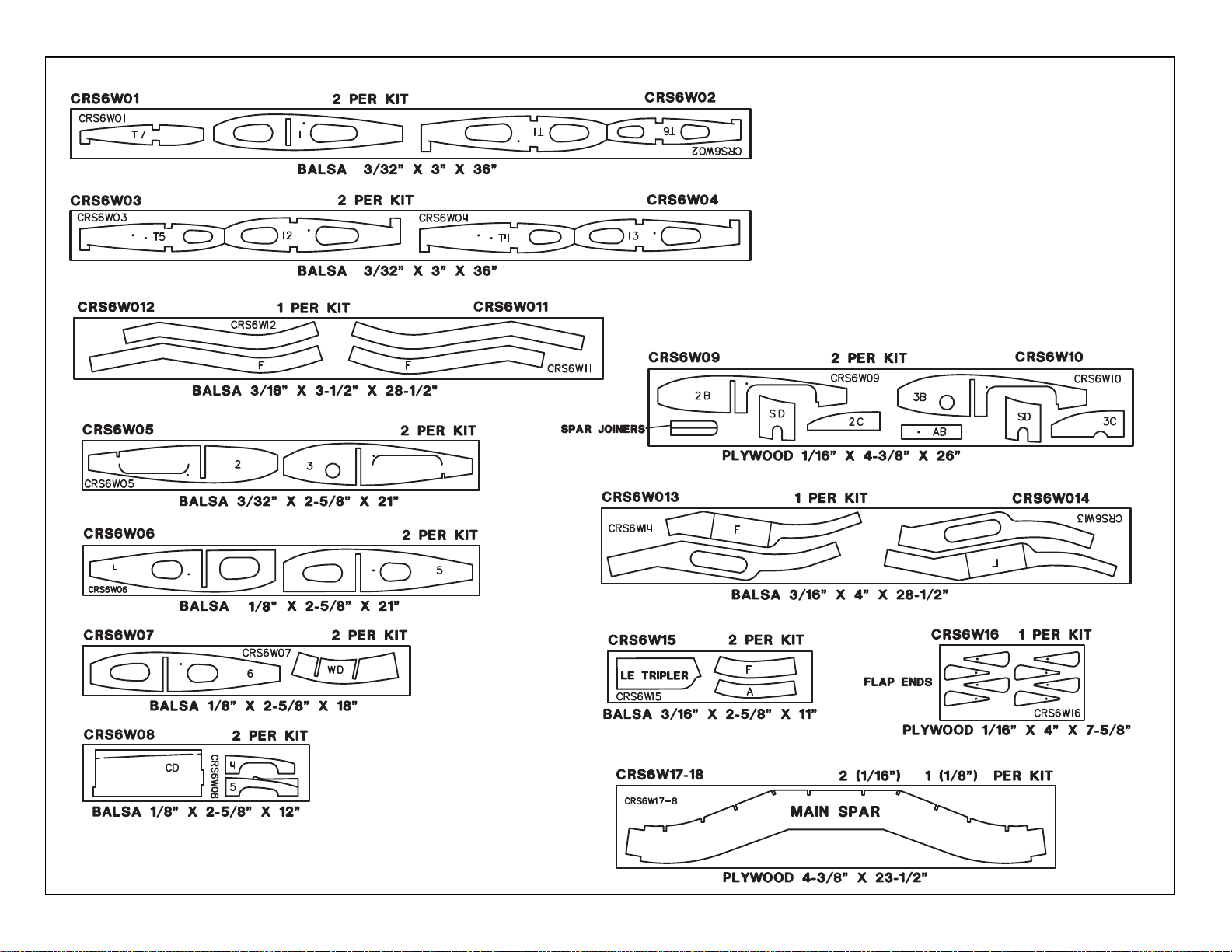
DIE-CUT PARTS
Page 5
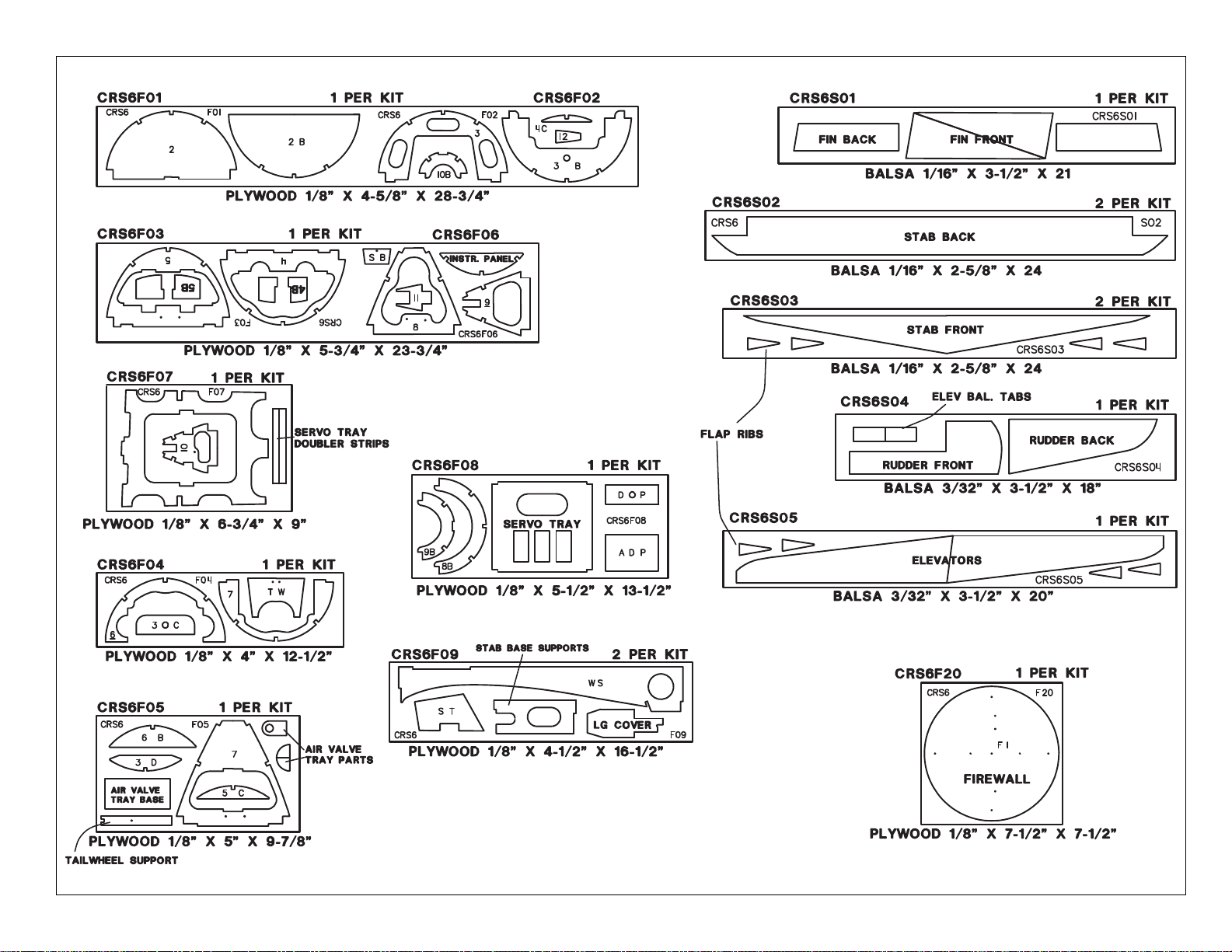
5
DIE-CUT PARTS
Page 6
SUPPLIES AND TOOLS NEEDED
❏ 2 oz. Thin CA Adhesive (GPMR6003)
❏ 2 oz. Medium or Thick CA (GPMR6009)
❏ 6-Minute Epoxy (GPMR6045)
❏ 30-Minute Epoxy (GPMR6047)
❏ Hand or Electric Drill
❏ Drill Bits: 1/16", 3/32", 1/8", 5/32", 3/16",
13/64", 7/32", 1/4", and 5/16"
❏ Soldering Iron & Silver Solder
❏ Sealing Iron (TOPR2100)
❏ Heat Gun (TOPR2000)
❏ Hobby Saw (Razor Saw)
❏ Hobby Knife, #11 Blades
❏ Plier
❏ Screwdrivers (Phillips & Flat Head)
❏ T-Pins (HCAR5150)
❏ Straightedge
❏ Short Ruler
❏ Masking Tape (required for construction)
❏ Sandpaper (coarse, medium, fine grit)*
❏ Bar Sanders (see below)
❏ Waxed Paper
❏ Lightweight Balsa Filler (HCAR3401)
❏ 1/4-20 & 8-32 Tap, (GPMR8105) (GPMR8103)
❏ Tap Wrench
❏ Isopropyl Rubbing Alcohol (70%)
❏ Rotary tool (Dremel
®)
) or similar (optional)
On our workbench, we have four 11" Great
Planes®Easy-Touch™Bar Sanders, equipped
with #50, #80, #150 and #220-grit sandpaper.
This setup is all that is required for almost any
sanding task. Custom sanding blocks can be
made from balsa for sanding hard to reach spots.
We also keep some #320-grit wet-or-dry
sandpaper handy for finish sanding before
covering. Great Planes Easy-Touch Bar
6
DECISIONS YOU MUST MAKE
EARLY IN THE
BUILDING SEQUENCE
ENGINE AND MOUNT SELECTION
The recommended engine size range is as follows:
.60 to .90 cu. in. 2-stroke
.90 to 1.20 cu. in. 4-stroke
NOTE: The smaller engines in the range provide
more than enough power to fly the Corsair well. Do
not hesitate to use them.
The instructions show an OS®.61 2-stroke engine
side mounted at a 45 degree inverted position. It
also shows a Top Flite internal muffler
(TOPQ7915). This power package works very well.
Most .61 2-stroke engines will fit in the supplied
EM60120 engine mount.
The instructions also show the installation of an OS
1.20 4-stroke engine. Even though it is shown
mounted inverted, it could also be mounted upright
or on its side; the decision is yours. Flexible exhaust
systems are available for most 4-stroke engines and
there is more than enough room inside the Corsair’s
cowl to route the exhaust out the bottom. You would
also have to change the cowl mounting. The engine
is shown on the plans mounted to a JT-122 SV
isolation mount which may no longer be available.
The supplied EM60120 mount will fit the O.S. 1.20.
FULL COCKPIT
(Optional)
You must decide before you build the fuselage if
you will be adding the optional full cockpit kit
(TOPQ8404) to your Corsair. If you are undecided,
you should build it as though you are going to
install it. That way you can add it at a later time
should you want to.
FLAPS
You must decide early in the building process if
you are going to use operating wing flaps. These
are not required but do add to the Corsair's
appearance and flyability. The flaps as described
in this manual work very well, giving super stable
slow flight with virtually no trim changes. Obviously
there is some extra work and craftsmanship
required to fit operating flaps to the model. If you
use operating flaps, you will need to have (2)
standard servos and small Robart hinge points
(ROBQ2508) available during construction.
RETRACTS
You will need to decide early whether you intend to
use retractable landing gear in your Corsair.
Robart 100 degree rotating retracts (ROBQ1815)
were used in the prototypes and the rib spacing
and mounts in the kit are designed to accept them.
Century Jet Models 90 degree rotating retracts
(CJMQ3055) will also work as well. Other retracts
have not been tested.
COMMON ABBREVIATIONS USED IN
THIS BOOK AND ON THE PLANS:
Deg. = Degrees Ply = Plywood
Elev = Elevator Rt = Right
Fuse = Fuselage Stab = Stabilizer
LE = Leading Edge TE = Trailing Edge
(front) (rear)
LG = Landing Gear " = Inches
Lt = Left Tri = Triangle
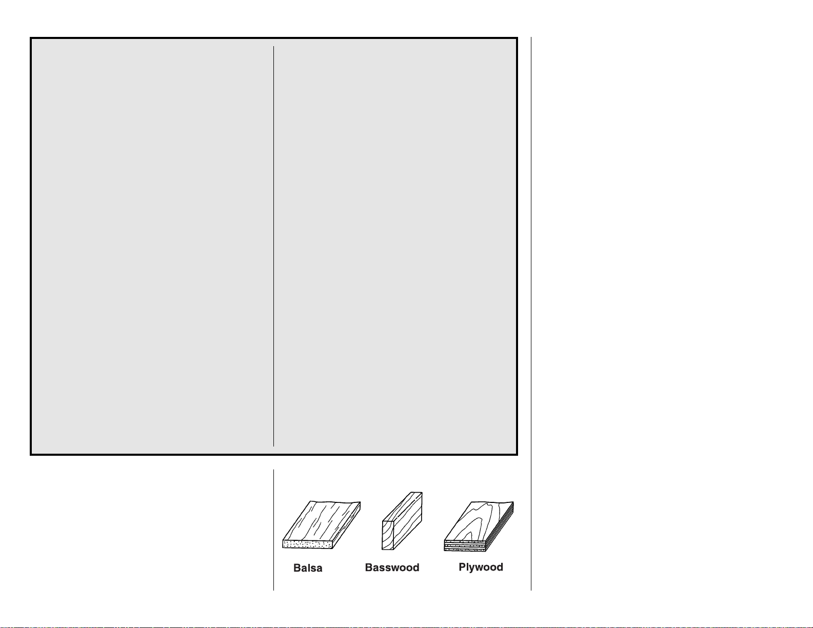
TYPES OF WOOD
Page 7
Sanders are made from lightweight extruded
aluminum and can be found at most hobby shops.
They are available in three sizes – 5-1/2"
(GPMR6169) – 11" (GPMR6170) for most general
purpose sanding and 22" (GPMR6172) for long
surfaces such as wing leading edges. We
recommend using the 2" wide self-adhesive
sandpaper sold in 12' rolls by Great Planes.
Standard sandpaper can be attached by gluing it
to the sander with brush-on rubber cement. Apply
the rubber cement to both the bottom of the
sander and the back of the sandpaper. When both
surfaces are dry to the touch, press the sandpaper
firmly onto the sander. Spray adhesive can be
used for this purpose but it’s much harder to
remove the sandpaper when you need to replace
it. Use a knife blade for cutting sandpaper, not
your good scissors!
GET READY TO BUILD
❏
1. Unroll the plan sheets. Reroll the plan sheets
inside out to make them lie flat.
❏ 2. Remove all parts from the box. As you do,
determine the name of each part by comparing it
with the plan. Using a felt-tip pen, write the part
name or size on each piece to avoid confusion later.
Use the die-cut patterns shown on pages 4 and 5 to
identify the die-cut parts and mark them before
punching out. Save all scraps. If any of the die-cut
parts are difficult to punch out, do not force them!
Instead, first cut around the parts with a hobby knife.
After punching out the die-cut parts, use your bar
sander or sanding block to lightly sand the edges to
remove any die-cutting irregularities.
❏ 3. As you identify and mark the parts, separate
them into groups, such as fuse (fuselage), wing, fin
and stab (stabilizer), and hardware.
BUILD THE STAB
❏
1. Arrange the stab portion of the plan on a
flat building board (you may wish to cut out the
stab section). Cover the area over the stab with
waxed paper.
7
OTHER ITEMS REQUIRED
❏ Four-Channel Radio with 4 servos (additional
channels and servos required if retracts and/or
flaps are used).
❏ Top Flite Power Point
®
Propellers (see engine
instructions for recommended sizes)
❏ Prop Safety Nut (Great Planes has sizes and
styles that work nicely)
❏ 12 oz Fuel Tank (DUBQ0212)
❏ 5/32" Wheel Collars - 4 (GPMQ4306)
❏ 3/32" Wheel Collars - 2 (GPMQ4302)
❏ Top Flite MonoKote Covering Material (Insignia
Blue and Yellow)
❏ Fuelproof Paint* for Cowl, Canopy and Oil
Coolers (Top Flite LustreKote™recommended)
❏ Latex Foam Rubber Padding, 1/4" thick
(HCAQ1000)
❏ Silicone Fuel Tubing (GPMQ4131)
❏ Plastic Pilot: Williams Bros. Standard, 2" Scale
#17600 (WBRQ1050)
❏ Main Gear Retracts (optional)...Robart #615
(ROBQ1815) Century Jet 33325 - complete
kit (CJMQ3055)
❏ Air Control Kit (optional retracts)...Robart
#188VRX (ROBQ2307) (Not required with CJ
33325)
❏ Oleo Robo Struts (optional)...Robart #650
(ROBQ1700) (Not required with CJ 33325)
❏ Hinge Points (optional flaps)...Robart #308
(ROBQ2508)
❏ 3-1/4" Main Wheels...Robart #134 (ROBQ1534)
❏ 1-1/4 Tail Wheel (GPMQ4242)
❏ .60 to .80 2-stroke, .90 to 1.20 4-stroke
NOTE: Top Flite “LustreKote Paint” matches
MonoKote covering and is available in aerosol cans.
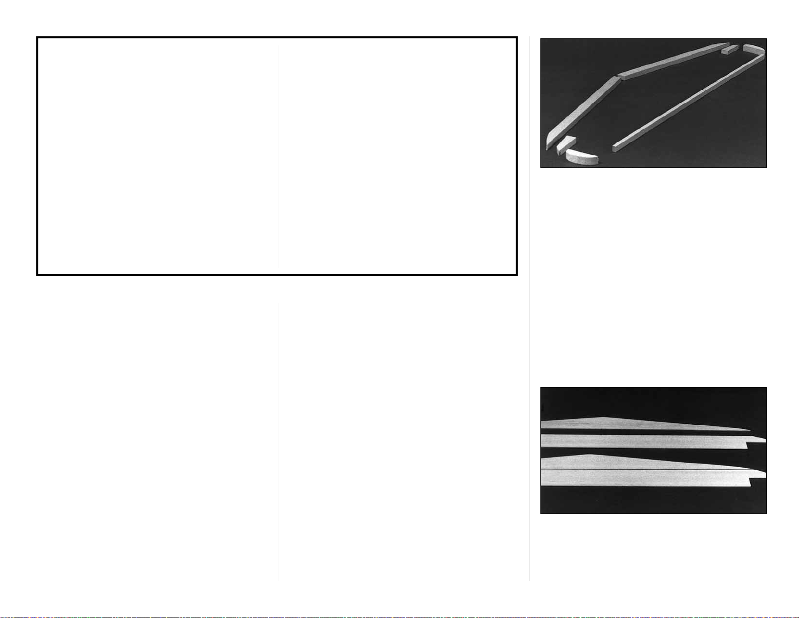
❏ 2. Cut the balsa 3/8" x 5/8" x 24" LE stock to fit
nicely at the center joint. Save excess material for
the fin LE. Trim the tip of the LE to the approximate
shape on the plan but leave about 1/16" excess for
final shaping later.
❏ 3. Cut the balsa 1/4" x 3/8" x 30" TE stock to
the correct length. Extra material is kept for the Fin.
❏ 4. Cut the two elevator tip blocks from the 1/2"
x 1/2" x 4" balsa stick provided. Shape the tips to
match the plan shape.
❏ 5. Make the stab tips from excess 3/8" x 5/8" LE
stock. Set the previously made parts aside for now.
❏ 6. Make a top and bottom stab skin by placing
the 1/16" die-cut balsa pieces, stab front and stab
back, together over waxed paper and glue them
together with thin CA. Block sand the skins lightly
with 220-grit sandpaper.
Page 8
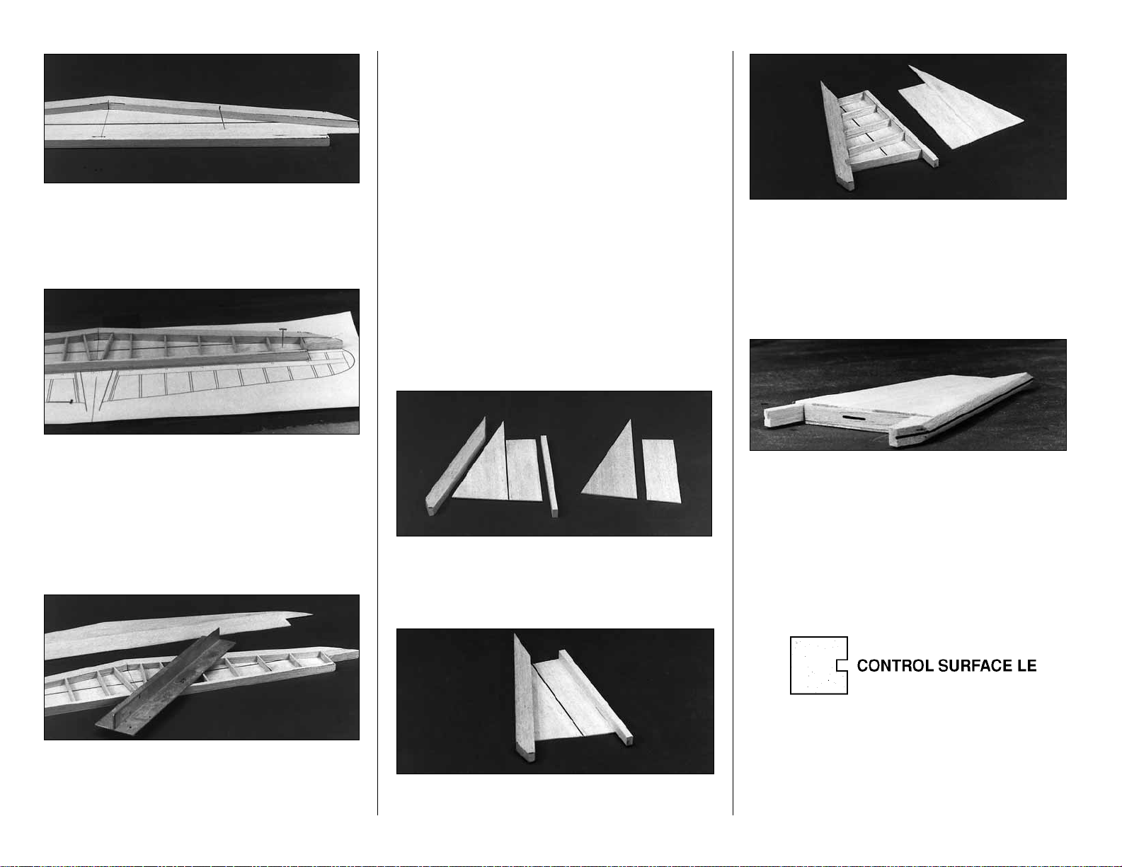
❏ 7. Pin the bottom skin to the stab plan. Draw
tick marks for the rib spacing on the skin to match
the plan. Glue the LE and TE pieces on top of the
bottom skin.
❏ 8. Cut the “ribs” from two 3/32" x 3/8" x 24"
balsa sticks. Align them with the “tick” marks and
glue in place. Do not overlook the two angled
pieces in the center over the fuse stab base.
❏ 9. Check the fit of the stab tips. Sand if
necessary, then glue them in place.
❏ 10. Use a bar sander to flatten the top of the
exposed structure. No parts should be left high or
low. Check all glue joints and add glue to any that
appear weak.
❏ 11. Glue on the top stab skin with medium or
slow CA. Be sure to apply glue to all ribs as well
as the LE and TE.
❏ 12. True the stab tips to match the die-cut
stab skins.
❏ 13. Draw a centerline around the stab to help
you maintain symmetry during sanding. Rough
shape the LE and the tips to the approximate cross
section shown on the plan.
BUILD THE FIN
❏
1. Trim the 3/8" x 5/8" LE and the 1/4" x 3/8" TE
to match the plan. Notice that they extend down
into the formers.
❏ 2. Make a left and a right fin skin by placing the
die-cut 1/16" balsa fin front and fin back together
over waxed paper and applying thin CA to the joint.
Block sand lightly.
❏ 3. Pin the right skin to the plan. Glue the LE and
TE on top of the skin.
❏ 4. Cut to length and glue in the 3/32" x 3/8"
“ribs” where indicated on the plan.
❏ 5. Block sand the structure until it is flat.
❏ 6. Use medium CA to glue the left fin skin to all
the ribs, the LE and the TE.
❏ 7. Draw a centerline around the fin to assist you
in hinging and shaping. Shape the LE of the fin to
match the cross section on the plan.
BUILD THE ELEVATORS
❏
1. Place the 3/32" balsa die-cut elevators over
the plan. Mark the locations of the “ribs” on both
sides of both elevators.
❏ 2. From the grooved 1/2" x 1/2" x 30" balsa
control surface LE, cut two pieces to the length
shown on the plan.
❏ 3. Slide the elevators into the slot in the control
surface LE’s. Glue with CA.
8
Page 9
❏ 4. Hang the LE’s over the edge of the table and
glue the 3/32" x 1/4" “ribs” (made from 3/32" x 1/4"
x 30" balsa) to the elevators at the locations
marked earlier.
❏ 5. Flip the elevators over onto their other side
and glue the “ribs” onto the second side.
❏ 6. Center the 3/32" die-cut balsa balance tabs
on the forward surfaces of the elevator LE’s. Glue
them in position as indicated by the plan.
❏ 7. Glue the elevator tip blocks (cut earlier) to the
end of the elevators.
❏ 8. Cut 2" balsa balance tab LE’s from 1/4" x
1/2" stock. Glue them to the front edge of the
elevator as shown on the plan.
❏ 9. Cut balance tab root cap strips from leftover
balsa 3/32" balsa. Glue them to the root end of the
balance tabs as shown on the plan. Glue a rib to
the balance tab (made from 3/32" x 1/4" x 30"
balsa) between the tip and the root cap strip.
❏ 10. Make doubler caps for the root end of each
elevator from leftover 1/8" balsa. Glue a cap to the
root end of each elevator. Make four torque rod
doublers (see plan for shape and location) from
leftover 3/32" balsa. Glue them to both sides of the
elevators in the locations shown on the plan.
❏ 11. Sand the tip of each elevator to match the
outline on the plan.
❏ 12. Use a bar sander to sand the ribs to match
the typical cross-section on the plan. Note that
there is some outward curvature to provide the
scale ribbed appearance.
❏ 13. Tape the elevators to the stab for blending
and shaping.
❏ 14. Remove the elevators and shape the LE to a
“V” as shown on the cross-section if you are using
the standard hinging technique. (See the Hinging
section and the plan sheets for alternatives.)
BUILD THE RUDDER
❏
1. Trim the grooved 1/2" x 1/2" balsa LE (left over
from the elevators) to the length shown on the plan.
Cut the balance tab LE from the 1/4" x 1/2" stock.
❏ 2. Join the 3/32" die-cut balsa rudder pieces,
rudder front and rudder back together with CA.
Mark the “rib” locations on both sides of the rudder.
❏ 3. Glue the rudder sheet into the slot in the
rudder LE.
❏ 4. Cut “ribs” from the 3/32" x 1/4" x 30" balsa
sticks and glue them to both sides of the rudder.
❏ 5. Glue the 1/4" x 1/2" balance tab LE to the
front edge of the rudder.
Photo for steps 1-6
❏ 6. Make doublers from leftover 3/32" sheet to
reinforce the area where the torque rod protrudes
into the rudder (see plan for location).
❏ 7. Shape the rudder to match the photos and
the typical cross-section on the plan. Tape the
rudder to the fin for shaping.
❏ 8. Shape the LE to a “V” as shown on the
cross-section if you are using the standard
hinging technique.
9
Page 10
BUILD THE WING
WING CENTER SECTION
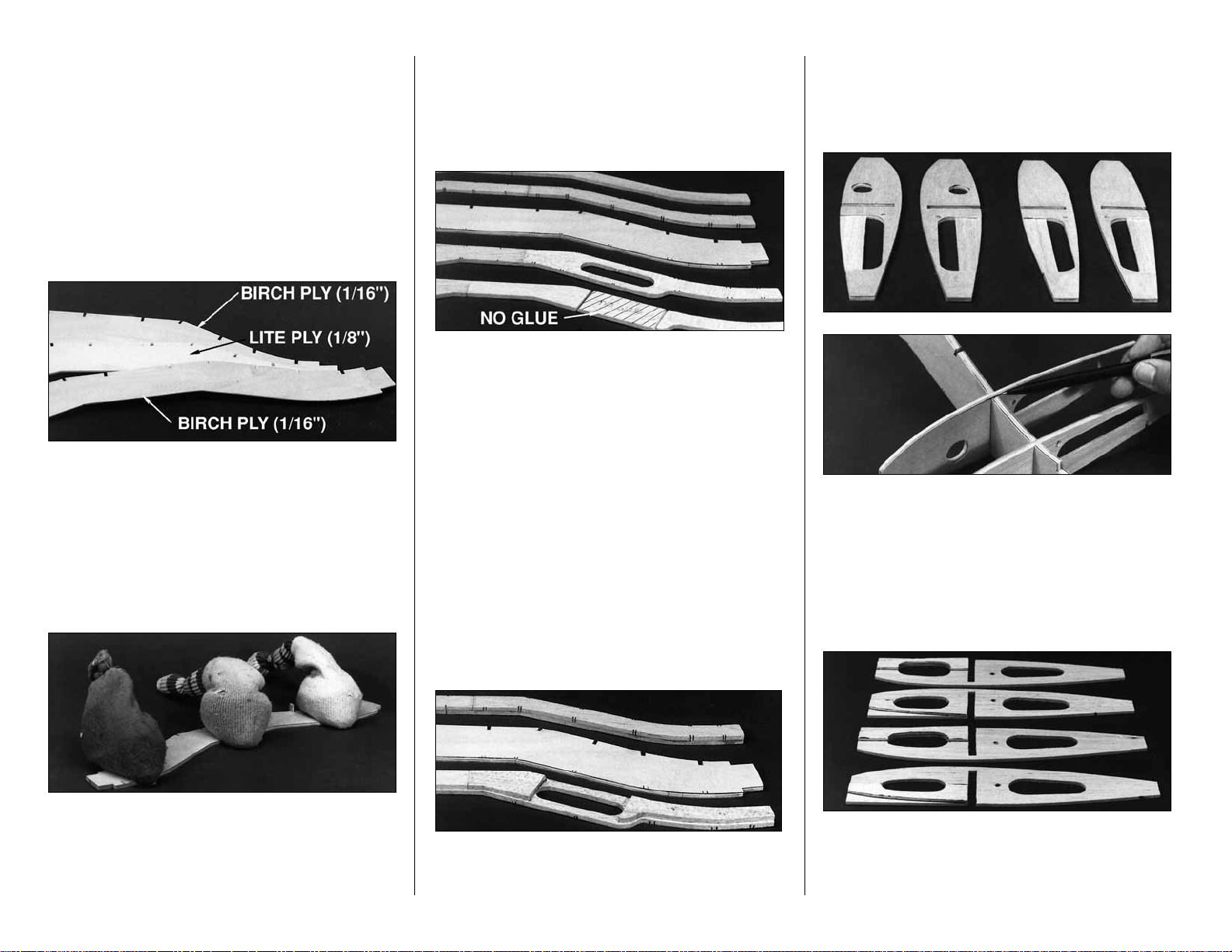
NOTE: The center section main spar is made of one
die-cut 1/8" plywood piece sandwiched between two
die-cut 1/16" birch plywood pieces.
NOTE: The wing root ribs are stamped only with a
number (2 is R-2), the wing tip ribs are stamped
with T and a number (T 4 is T-4).
❏ 1. Lightly sand the surfaces of the three pieces
that make up the main spar to make sure they will
lie flat together for a good glue joint.
❏ 2. Make some short sticks from leftover 1/8"
balsa to key the rib slots together and assure
proper alignment during gluing. Test fit pieces.
❏ 3. Use 30-minute epoxy to glue the spar pieces
together. Use weights to hold them flat on the
table while the glue cures. Apply thin CA on the
edges of the spar, especially to areas that do not
appear to be well glued.
❏ 4. Clean up the edges of the spar with
sandpaper. If you will be installing retracts, you
may want to cut any holes required for your
retracts in the spar at this time. See the
instructions that came with your retracts.
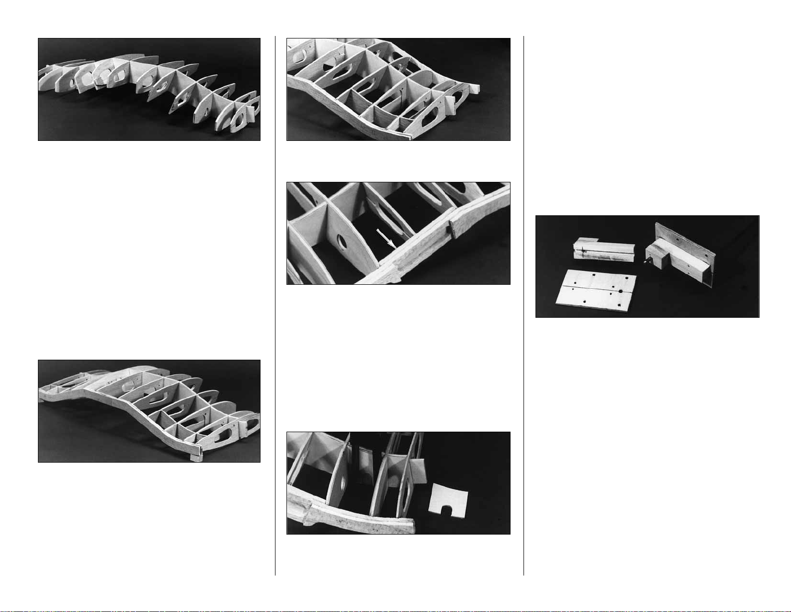
❏ 5. Join the die-cut 3/16" balsa aft leading edge
pieces at the center over the template provided on
the plan. Use the plan to mark the rib locations on
the aft LE. Glue the die-cut 3/16" balsa fwd
leading edge pieces to the aft leading edge.
(Center the fwd leading edge on the aft leading
edge as shown on the cross-sectional view.) Refer
to the photo - do not put glue where indicated.
❏ 6. Join the die-cut 3/16" balsa fwd trailing edge
pieces at the center over the template provided on
the plan. Use the plan to mark the rib locations on
the fwd TE. Glue the die-cut 3/16" balsa aft trailing
edge pieces to the fwd trailing edge. (Center the aft
trailing edge on the fwd trailing edge as shown on
the cross-sectional view.)
❏ 7. The hatched area of the forward LE which was
not glued may be cut loose with a razor saw and
removed after the glue has set on the rest of the part.
❏ 8. Drill 3/16" holes through all ribs and doublers
that require them for aileron linkage routing. These
holes are located by punch marks in the ribs just
aft of the spar.
❏ 9. Glue the die-cut 1/16" plywood R-2B rib
doublers to the die-cut 3/32" balsa R-2 ribs. Glue
the plywood R-3B rib doublers to the balsa R-3
ribs. Be sure to make a left and a right of each
assembly. Trial fit the R-3 assembly into the spar
slot – you may find it necessary to bevel the
plywood doubler along the top side a little for a
smooth transition.
❏ 10. Glue the die-cut 1/8" balsa R-4B sub ribs to
the die-cut 1/8" balsa R-4 ribs. Glue the R-5B sub
ribs to the R-5 ribs. Be sure to make a left and a
right of each assembly.
10
Page 11
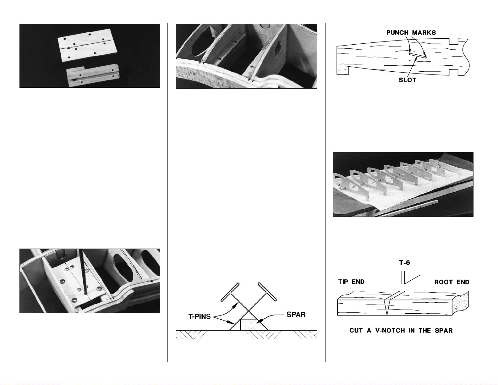
❏ 11. Plug the die-cut ribs R-1 to R-6 into the
spar. Hold this assembly over the plan to make
sure the ribs are perpendicular to the spar and not
skewed. When you are satisfied that all ribs are
fitting properly, lightly glue them in place with a
drop of CA. You will glue all these joints thoroughly
after the LE, TE and a few other parts are installed.
❏ 12. Make a couple of 1/2" tall balsa blocks to
support the ends of the R-1’s and prevent the center
section from twisting. Tack glue these to the R-1’s.
❏ 13. Slide the die-cut balsa well doublers (WD)
into place - do not glue yet.
❏ 14. Glue the TE assembly in place. Check the
center section on a flat table to be sure it is not
twisted. Flex and reglue joints to take out any warps.
❏ 15. Align the LE assembly onto the front edge
of the wing. Glue only to ribs R-1, R-2 and R-3.
❏ 16. Glue the die-cut 3/16" balsa LE triplers in
place between R-3 and R-5. Glue ribs R-4 and R-5
to the LE.
❏ 17. Glue both 1/8" die-cut plywood dowel
plates (DP and ADP) in place as shown on plan.
Glue the R-6’s to the LE. Drill a hole through the
LE of the wing through the hole in the forward
dowel plate (DP). Start with a small drill and
gradually increase the size to 5/16".
❏ 18. If you are using retracts, glue in the die-cut
1/16" plywood spar doublers (SD) on both sides
of the spar using 30-minute epoxy. Cut a notch in
the main spar to match the strut cutout in (SD).
The notch will probably need to be deepened
slightly during final retract fitting. Keep this cut
smoothly radiused to prevent the creation of a
weak spot in the wing. A small Dremel
®
drum
sander is helpful here. See Page 42 for details on
retract installation.
19. If you are using fixed landing gear, assemble
both sets of fixed gear parts with 30-minute epoxy
as follows:
❏ A. Drill the holes in the 1/8" x 1-13/16" x 3"
5-ply plates using the pattern on the wing plan.
❏ B. Glue each basswood 7/16" x 5/8" x 7/8"
landing gear retainer block to a grooved bass
landing gear mount.
❏ C. Refering to the drawing on the wing plan, drill
a 5/32" hole where shown into each Grooved LG
mount and through each LG retainer block.
❏ D. Slide a 1/8" plywood plate onto each main
landing gear wire. Trial fit the LG block assemblies,
relieve any parts if necessary to allow the 1/8" plates
and the block assemblies to almost come together
(a little pressure during final assembly is good).
NOTE: The wire Landing Gear in the kit differs in
appearance from the wire LG in the photos.
❏ E. Drill the four 5/64" holes shown in each
basswood block assembly for the #4 x 1/2" sheet
metal screws, using the 1/8" plate as a pattern.
11
Page 12
❏ F. Disassemble the parts and enlarge the hole
drilled in the previous step in the 1/8" plate to 1/8"
for clearance.
❏ G. Reassemble the fixed gear parts.
❏ 20. Measure and drill the gear mounting holes in
the 1/4" x 5/16" x 3" plywood mounting rails.
Mount the fixed gear plates or retracts – test fit
between R-2B and R-3B while holding the 1/16"
die-cut plywood R-3C gear reinforcement tripler in
place (if you are using retracts, make sure the
retract will clear the wing skins). Adjust the height of
R-3C if necessary. Do this for both wing panels.
❏ 21. Glue the R-3C’s in position.
❏ 22. Tilt the LG assemblies (fixed or retract) until
the struts protrude straight down (the left and right
struts should be parallel to each other and
perpendicular to the ground). Check the fit of the
R-2C’s, adjust their height if necessary, then glue
them in place. Glue in the mounting rails.
❏ 23. Remove the LG assemblies and apply a
small fillet of 30-minute epoxy to all joints involving
plywood in the landing gear mounting areas. Apply
some epoxy to the dowel plate joints also.
❏ 24. Glue all ribs to the spar. Glue both WD’s to
ribs R-1, R-2, R-3 and R-4. Reinforce any glue
joints that appear weak.
TIP PANELS
NOTE: The tip panels are built “UPSIDE-DOWN”
on the plan (the jig tabs are attached to what is,
in the end, the TOP surface of the wing.)
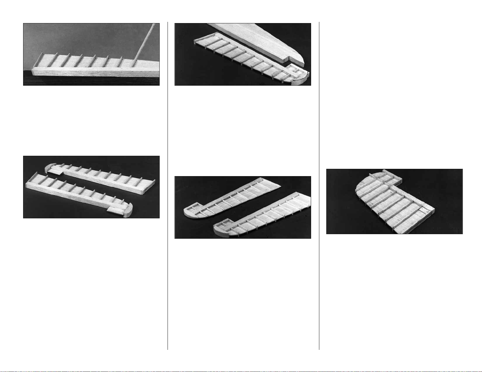
❏❏1. Place the tip panel plan over a flat building
board (you may wish to cut out these sections of the
plan sheet). Cover with waxed paper.
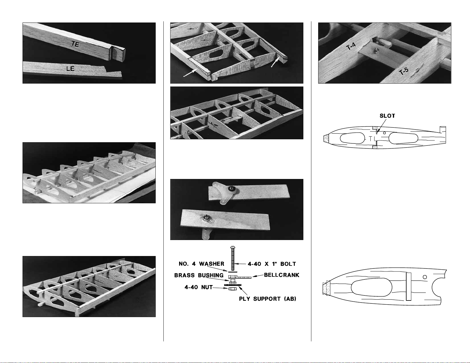
❏❏2. Cut the top 1/4" x 3/8" x 20" hard balsa
spar to length. Pin it in place over the plan.
❏❏3. Cut a 1/16" slot in the 3/32" balsa die-cut
ribs T-4 and T-5 between the punch marks
provided to allow the bellcrank platform to slide in
place later.
❏❏4. Glue die-cut 3/32" balsa ribs T-1 through
T-7 to the spar with the jig tabs at the TE flat
against the work surface.
❏❏5. Cut a V-notch in the bottom 1/4" x 3/8" x 20"
balsa spar so it can bend at T-6. Slide the bottom
spar into place. It will be glued in step 8.
12
Page 13
❏❏6. Notch the inner end of the shaped LE and
TE stock to match the plan.
❏❏7. Glue the TE to the ribs. Notice that T-7 is
glued flush with the top (toward plan) edge of the TE.
❏❏8. With the wing slightly weighted down so
the entire top spar and all the jig tabs rest on the
building board, apply glue to all joints involving the
bottom spar. Make sure the bottom spar is
securely glued at T-6 where it is notched.
❏❏9. Glue the LE to the ribs, centering it on all
ribs except T-7. T-7 is glued flush with top edge
(toward plan) of the LE.
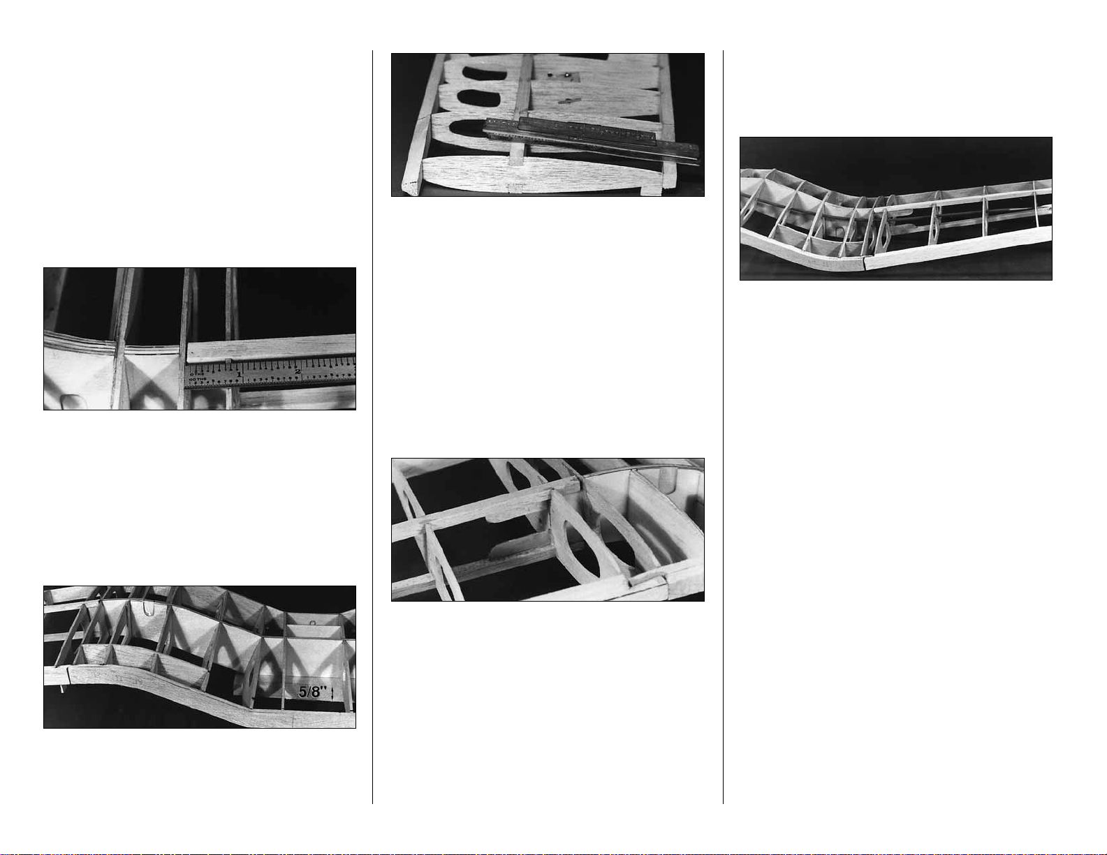
❏❏10. Draw lines with a pen and a straight
edge as shown in the photos to mark the tapering
of the bottom of the LE and TE. Use a knife and a
sanding block to carefully taper the LE and TE.
❏❏11. Assemble the bellcrank parts onto the
die-cut 1/16" ply support – make a left and a right.
Be sure to put a drop of 6-minute epoxy on the
thread and nut of the 4-40 bolt to prevent it from
vibrating loose.
❏❏12. Glue the bellcrank assembly securely in
place through the slots in ribs T-4 and T-5.
❏❏13. Cut a 1/16" x 3/8" slot in the top and
bottom of T-1 so the 1/16" plywood spar joiners
can pass through the rib and overlap the main spar
when the panels are joined.
REPEAT THE WING TIP PANEL STEPS 1-13 TO
BUILD THE OPPOSITE PANEL. BE SURE TO
MAKE A LEFT AND A RIGHT TIP PANEL.
WING JOINING
❏
1. Trim off all tip panel jig tabs except the tabs
on the T-7’s.
❏ 2. Sand the center section LE and TE (using a
block or sanding bar where possible) to approximate
the shape of the outer panel LE and TE. Be careful
13
Page 14
not to alter the shape of the ribs during this process
(masking tape can be used to help protect them).
Final shaping can be done after wing joining.
❏ 3. Trim the tip panel top and bottom spars so
they protrude 11/16" past T-1.
❏ 4. Notch the front of the center section LE to
accept the tip panel LE. Notch the back of the
center section TE to accept the tip panel TE.
❏ 5. Make any small adjustments necessary to
allow you to mate the tip panel with the center
section. Use a small ruler to check that ribs R-1
and T-1 can be positioned parallel and 11/16"
apart. Adjust if necessary to obtain a good fit.
NOTE: The 3/8" wide tip spar should be
centered over the 1/4" wide center spar.
❏ 6. Place the wing upside down on a flat table
with the balsa 5/8" x 2" x 6" dihedral jig block under
the center section. This sets the proper dihedral
when the tips are on the table surface.
❏ 7. Apply small weights to the tips of the wing. The
T-7 jig tabs and the spar tips should contact the table.
Adjust the LE and TE junctions of the tip and center
sections to align them and relieve any stresses.
❏ 8. Check again to see that R-1 and T-1
are parallel.
❏ 9. Tack glue the TE and spar joints with CA.
❏ 10. Carefully remove the tip weights and look at
the entire wing. Make sure there are no twists in
the wing. If there are any problems, pop loose the
wing joints and realign them.
❏ 11. Replace the wing tip weights and apply
30-minute epoxy to all joints involved. Use
30-minute epoxy to glue the die-cut 1/16" ply spar
joiners in place before the glue cures.
WING STRUCTURE COMPLETION
❏❏
1. Cut a piece of the outer pushrod guide
tube to 18". Roughen the outside of it with coarse
sandpaper. Carefully slide it in place through the
wing ribs. Glue it to all ribs it touches.
❏❏2. Cut a 20" piece of inner pushrod tube and
screw a 1" piece of threaded rod and a nylon clevis
into one end.
❏❏3. Use a sharp knife to cut a 5/16" sq.
window in T-4 where the pushrod passes through.
This will allow the pushrod to move slightly as the
bellcrank rotates.
❏❏4. Slide the inner pushrod tube into place
and connect the clevis to the bellcrank.
REPEAT STEPS 1-4 FOR THE OTHER SIDE OF
THE WING
❏ 5. If you have your aileron servo available it is
easiest to install it now. This will allow you to
confidently zero the bellcranks when the servo is in
its centered position. See plan for proper location
and mounting of the aileron servo. The aileron
servo is mounted on 3/16" x 3/8" plywood rails.
NOTE: The servo may protrude about 5/16" below the
bottom of R-6 into the belly-pan if necessary.
Skip steps 6 to 8 if you are using standard
sport ailerons and no flaps.
14
Page 15

❏ 6. If you are installing functioning flaps, install
the hinge reinforcement blocks shown on the wing
plan. These are cut from a 3/8" x 1/2" balsa stick
supplied. The flap reinforcement blocks (for Hinge
Points) rest against the bottom wing skin.
❏ 7. If you wish to use the “scale” type of aileron
hinging (see plan for a typical cross section), using
Hinge Points, install reinforcement blocks now. The
aileron reinforcement blocks are centered on the
TE.
❏ 8. Mark the hinge locations on the outside of the
TE so you can find them after the wing is sheeted.
❏ 9. In preparation for wing skinning, sand any
parts that protrude higher than the surrounding
parts. Any high spots will cause you to sand
through the wing skins after they are applied. It is
important to have a consistent structure if you want
a smooth skin.
❏ 10. Final sand the center section LE and TE to
blend them with the outer panel. The transition from
the LE to all the ribs may be slightly blended to
provide a smooth curve for the sheeting to bend over.
❏ 11. Do any final fitting of retracts at this time. If
you have chosen retracts that require external
actuation, rig them at this time.
❏ 12. Make the aileron pushrods from the 12" long
threaded end rods. Make a Z-bend in one end and
screw a nylon clevis on the other.
WING SHEETING
❏
1. Sort through the 1/16" x 3" x 24" balsa wing
sheeting, separating the best wood with the most
uniform grain for the top wing skins. Use the other
wood for the bottom skins.
❏ 2. True the edges of the wing sheeting by
placing a metal straightedge lengthwise on the
sheet. Position the straightedge about 1/32" from
the sheet edge. With a sharp knife, cut carefully
along the straightedge.
❏ 3. Place waxed paper on a flat smooth table.
You will join the wing skins on this surface.
❏ 4. Edge glue four wing sheets together with thin
CA for each of the four outer panel surfaces.
LIGHTLY sand both sides of the skin over the work
surface with a block and sharp 220-grit sandpaper.
❏❏5. Hold a skin over the bottom of the outer
wing panel. Mark the shape of the wing on the
skin, allowing about 3/16" extra on all sides. On the
wing bottom, the section between T-6 and T-7 is
sheeted separately from the section between T-1
and T-6. Cut off the tip of the skin and save it.
❏❏6. Connect the aileron pushrod to the
bellcrank. Make a small cut in the bottom skin to act
as a pushrod exit. Refer to the plan for its location.
NOTE: Before gluing the bottom wing skin, jig
the wing as before with the 5/8" block under
the center and the tips weighted on the table.
15
Page 16

❏❏7. Test fit the bottom skin. Make any
adjustments necessary for a good fit. Apply
medium or slow CA to all the structure that will
contact the bottom wing skin between T-1 and T-6.
Carefully position the bottom wing skin on the
structure between ribs T-1 and T-6. The skin
should cover half of the rib T-6. Hold the skin in
place until the glue cures (masking tape is often
helpful in holding skins in place while glue sets).
❏❏8. Do any trimming necessary to fit the skin
piece cut off at step 5, over ribs T-6 and T-7. Glue
the tip skin in place.
❏❏9. Make two 1/4" x 1" pushrod exit stiffeners
from leftover 1/16" balsa. Glue them in place around
the aileron linkage exit in the bottom wing skin.
REPEAT STEPS 5 to 9
FOR THE OTHER TIP PANEL
❏❏10. Cut the top outer panel wing skins from 2
remaining blanks made earlier. The top tip panel is
skinned in one piece from the center of T-1 to T-7.
❏❏11. When you are ready to skin the top of the
wing, cut the remaining jig tabs off the T-7’s. Be
careful not to twist the tip panels while
applying the top skin.
❏❏12. Apply medium or slow CA to all structures
that will contact the top wing skin. Position the top
wing skin on the structure and hold it in place until
the glue sets.
REPEAT STEPS 10 to 12
FOR THE OTHER TIP PANEL
❏ 13. Trim and sand the edges of all tip panel
wing skins with a knife and bar sander.
❏ 14. Refer to the photos and plan to see the grain
directions of the sheeting on the top of the wing
center section. All sheeting in the top center section
is applied in prejoined sections as in photos. Study
the photos in this section...when making the skins
with angled grain, cut the sheets at 45 degree
angles to conserve wood. The grain direction shown
for these wing skins represents the best technique
for sheeting the Corsair’s bent wing.
NOTE: You may find it faster and easier to do
both left and right wings at the same time to
avoid having to determine the sheet shapes
twice. Skin sizes given are approximate.
❏ 15. Make a slightly oversize skin to cover the
area forward of the spar from R-3 to T-1. Trim the
wood until it fits well along the edge at T-1.
❏ 16. Wet the outside of the skin with a water
soaked paper towel. Glue the skin in place starting
at T-1. You may apply glue from the underside of
the wing structure.
❏ 17. Trim the skin edges to the middle of the
spar and the middle of R-3.
16
Page 17

❏ 18. Make a skin to cover the area aft of the spar
from R-5 to T-1. Wet the skin and place it over the
structure. Trim it so it fits well at T-1 and at the
spar. Glue the wet skin to the structure.
Photo for steps 19-20
❏ 19. Make a skin for the section forward of the
spar from R-5 to R-3. Glue this piece on dry.
❏ 20. Skin the top of the wing between the two R-5’s.
❏ 21. Add some CA to any questionable center
section top wing skin joints from the bottom side of
the wing.
❏ 22. If you are using flaps, install the servos now.
They are mounted on 3/16" x 3/8" plywood rails
between ribs R-4 and R-5. Notice that one servo is
mounted inboard in the bay and one is mounted
outboard. This allows both pushrods to exit at the
center of the bay. Route the servo leads to the
center as shown. (A Y-harness is used to connect
the two flap servos together. Plug the Y-harness
into the receiver and use it as an extension.)
NOTE: The ribs were changed slightly after the
photos were taken to make it easier to mount the
servo rails.
❏ 23. Make the flap pushrods from two 12"
threaded end wires. Use nylon clevises at one end
of the wires and make Z-bends at the other. When
the servos are centered the clevis pins should line
up with the seam between the two 3/16" TE
laminations.
NOTE 1: If you are using fixed gear, the standard
procedure is to securely screw the fixed gear into
place before proceeding to sheet around the wire
strut. An alternative is to proceed as you would
with the retracts. Sheet the bottom of the wing with
no gear installed and cut out an opening for
installing the fixed/retract gear after sheeting is
completed. A balsa block (not supplied) could be
glued to each fixed gear plate (with holes drilled to
access mounting bolts) and faired into the bottom
of the wing. This technique allows you to remove
the fixed gear for servicing.
NOTE 2: All of the bottom wing sheeting is cut from
the remaining 1/16" x 3" x 24" balsa sheeting. Study
the photos in this section before proceeding. You may
find it faster and easier to do both left and right wings
at the same time to avoid having to determine sheet
shapes twice. Indicated skin sizes are approximate.
NOTE 3: Parts of the center section will be
covered by the belly-pan. Do not fill small misfits in
this area until after the belly-pan is installed.
❏ 24. Cut a 1-1/2" x 10" piece of 1/16" wing skin.
Glue it behind the main spar, starting at the aft half
of the main spar.
❏ 25. Next, glue a 1-1/2" x 7" piece forward from
the center of the main spar. This sheet covers from
R-4B outward to T-1.
17
Page 18

❏ 26. Continue forward until you reach the LE with
narrower strips (3/4" to 1"). It will be necessary to
curve the aft edge of the strips to allow them to
conform to the structure.
❏ 27. Glue a 3" wide sheet over the center section
between two R-5’s. The R-5B’s serve as a shelf to
support this sheet.
❏ 28. Locate the small 1/8" die-cut R-5C sub ribs.
Cut off the small die-cut bump at the narrow end so
the part tapers to a point. Glue it in place at the
outboard end of the oil cooler as shown in the photo.
❏ 29. Make a piece of skin to cover the bottom of
the oil cooler from the center of the spar forward to
the LE. Study the photos. Notice how the sheet
blends into the center of the wing. Cut out a small
piece of wing sheeting between R-3 and R-4 just
forward of the main spar. This will allow the oil
cooler sheeting to blend in smoothly.
❏ 30. Glue the oil cooler skin in place.
❏ 31. Continue sheeting aft in 1-1/4" to 1-1/2"
increments. Allow the flap pushrods (if any) to exit
as shown.
❏ 32. Sheet the rest of the wing center section
between the R-5’s. The rectangular hole shown
allows the aileron servo to protrude into the belly-pan.
❏ 33. Cut out the vacuum formed oil coolers just
below the faint cut line on the inside. Use coarse
sandpaper to sand the part exactly to the line.
❏ 34. Place the oil cooler on the wing. Trace its
location onto the LE of the wing. Cut away balsa
under the oil cooler until it will blend nicely into the
wing. You will need to remove a fair amount
of wood.
❏ 35. Glue the oil cooler to the wing. Shape the
surrounding area to blend into the formed oil coolers.
Lightweight filler may be used to fill any gaps.
❏ 36. Use a portion of the provided 3/8" x 1/2" x 24"
stick to fair the outboard ends of the oil coolers.
The wing will be completed after the
Fuselage Construction.
18
Page 19

FUSELAGE TOP
NOTE: The 1/8" die-cut plywood formers are
stamped only with the necessary portion of their
name (F-3B is stamped 3-B).
IMPORTANT: All formers should be installed with
the STAMPED IDENTIFICATION NUMBER
FACING FORWARD. This is necessary to line up
the pushrod holes.
❏ 1. Cut out the Top View of the fuselage. Tape it
to the building board and cover it with waxed paper.
❏ 2. Pin the 1/8" die-cut forward frame accurately
over the plan. Be sure the outline fits the plan
exactly as this establishes the engine offset
thrust angle.
NOTE: Use a small triangle to hold all formers
vertical while gluing. Any small warps or twists in
the formers can be taken out when the 3/16" sq.
stringers are glued in place.
❏ 3. Glue F-3 into the forward half of the slot in
the middle of the forward frame.
❏ 4. Glue F-2 to the forward edge of the forward
frame. It is centered by the interlocking tab.
❏ 5. Separate the two 42" long shaped balsa
main fuselage stringers by running a knife
vertically against the edge where they are joined.
Sand the edges if necessary.
❏ 6. Position the main fuselage stringers in the
former notches so the ends protrude about 1/16"
forward of F-2. Notice that the 1/8" slots in the
main fuselage stringers are more toward the
bottom of the fuse (toward the table). Glue the
stringers to F-2, F-3 and the forward frame
❏ 7. Glue F-4 in place at the aft end of the forward
frame. The notch at the center of F-4 engages the
tab on the forward frame (see photo at step 10).
❏ 8. Drill 3/16" holes where indicated by punch
marks in F-5, F-7, F-8 and F-10. The pushrods will
be installed through these holes later. Check that
all pushrod holes are offset slightly to the plane’s
left. These holes should line up for a virtually
straight shot.
❏ 9. Check your servos for fit in the 1/8" die-cut
servo tray. Make modifications if necessary. Glue
the 1/8" die-cut plywood servo tray doubler strips
to one side of the servo tray as shown. These will
stiffen the tray and give the servo mounting screws
extra material to bite into.
❏ 10. Position F-5 over the plan. Key the servo tray
in place as in the photo. Notice that the servo tray
doublers are facing up. Glue F-5 to the main stringer.
Remove the servo tray and apply medium CA to the
mating surfaces. Put the servo tray back in position.
❏ 11. Glue the two halves of the die-cut 1/8" balsa
cockpit deck (CD) together.
19
Page 20

❏ 12. If you are installing the optional cockpit kit,
glue F-7 and the cockpit deck in position as
indicated in the photo. Otherwise, trim off both edges
of the cockpit deck along the precut lines and install it
in the notches in the upper part of the formers.
❏ 13. Glue F-8, F-9 and F-10 to the main stringers
over their location on the plan. Be sure the pushrod
holes are properly oriented.
❏ 14. Trial fit F-11 on the main stringers. Test the fit
of the stab base supports in between F-10 and
F-11. The stab base support should rest flat on the
building board along its entire length. This is very
important as it sets the stab incidence. Remove a
little material from the interlocking joints if necessary
to allow the stab base support to rest on the building
board. Glue the stab base support and F-11 in
position with medium CA.
NOTE: If you are installing the optional cockpit kit,
install the instrument panel as shown in the following
steps. Otherwise, the instrument panel is glued to the
base of the cockpit deck 1-1/16" behind F-5.
❏ 15. Glue all the upper stringers in place as
shown in the photograph. Check the formers with a
90 deg. triangle during this process to make sure
they are vertical.
❏ 16. Fit the Instrument Panel into the stringers
1-1/16" to the rear of F-5. Insure that it is parallel
with F-5 and then glue it into position.
❏ 17. With a sanding block, smooth any glue joints
that will affect the sheeting of the fuselage. Sand the
main stringers slightly to blend with the formers.
❏ 18. Glue the four 1/8" x 1/4" x 24" balsa sub
stringers into the slots in each of the main
stringers. These will provide a shelf for the
sheeting to rest on.
NOTE: It is helpful to put some weight in the cockpit
to hold the fuse firmly on the building board. Leave
the fuse on the building board during sheeting.
❏ 19. Locate the 3/32" x 4" x 36" balsa lower fuse
side sheets. Place the shaped 3/32" balsa upper
fuse side over the lower fuse side sheets. Trace
the “bow” of the bottom edge of the upper fuse
side sheet onto the lower fuse side sheets as
shown in the sketch. Set the lower fuse side sheets
aside until they are needed.
❏❏20. Pin a shaped 3/32" balsa fuse side on
the fuselage frame. Align the rear edge of the fuse
side with the rear of F-12. Notice that the bottom
edge of the fuse side is curved up slightly. This
allows the wood to bend around the fuselage
frame without lifting the center of the fuselage off
the building board.
NOTE: A small amount of water applied to the
outside of the fuse side with a paper towel is
helpful when bending the fuse sides.
20
Page 21

❏❏21. Glue the balsa fuse side to the main
stringer only between F-5 and F-7.
❏❏22. Apply medium CA to the edge of F-5 and
F-7 and the lower edge of the instrument panel.
Bend the fuse side to meet them. Use thin CA to
glue the fuse side to the 3/16" sq. stringer between
F-5 and F-7.
❏❏23. Work your way forward and aft from this
point, one former section at a time. Glue the fuse side
to the main stringer (at bottom edge of sheeting) first,
then to the formers and upper stringer for that
segment. If you notice the center of the fuselage
trying to lift off the building board during this process,
trim a little wood off the bottom edge of the fuse side.
Repeat steps 20 to 23 for the other fuse side.
❏ 24. Keep the fuselage firmly pinned down on
the building board until all glue is cured and the
wood is dry.
❏ 25. Look at the fuselage side view on the plan
and notice F-12’s height off the building board.
Glue F-12 in place. Trim the aft end of the fuse
sides flush with F-12.
❏ 26. Use the pattern provided on the plan to cut
two forward deck sheets out of the
3/32" x 2-1/2" x 36" balsa sheet. Glue one deck
sheet in place starting at the edge of the fuse side.
Apply glue to the former and the top 3/16" sq.
stringer. Wrap the sheet around until it is glued to
the top stringer. Trim the sheet to the center of the
stringer. Repeat this process for the other forward
deck sheet.
NOTE: The sheeting will extend well beyond F-2 to
allow trimming for the engine offset.
❏ 27. Use the pattern on the plan to cut two aft
deck sheets out of the 3/32" x 3" x 24" balsa
sheet. Glue the aft deck sheets in place as shown
in the photo and on the plan.
21
Page 22

❏ 28. Use a sanding block to sand the top of the aft
deck sheeting down to the height of the former tops.
❏ 29. Place the 1/2" x 2" x 17-7/8" top deck block
on top of the fuse. Trace the shape of the fuse
onto the bottom of the block. Roughly cut the block
to shape.
❏ 30. Mark a 1/2" wide slot on the top deck block
that will allow the fin to protrude through. Notice
that the fin LE sweeps back. Cut the slot into the
deck block. Temporarily plug the fin into the slots in
formers F-9 and F-10. Adjust the slot in the deck
block if necessary for a satisfactory fit. Tack glue
the deck block to the fuse but do not glue the fin.
Remove the fin and thoroughly glue the deck block
to the fuse with thin CA.
❏ 31. Shape the deck block to match the cross-
section on the plan. A razor plane is helpful for this
kind of shaping.
❏ 32. Remove the fuselage from the building board.
❏ 33. Inspect the structure from the inside. Add
glue to any open joints.
FUSELAGE BOTTOM
❏
1. Cut two of the 24" outer pushrod guide
tubes to the lengths required for the rudder and
elevator pushrods (see fuse side view).
❏ 2. Roughen the outside of the pushrod tubes
with sandpaper. Slide the tubes through the 3/16"
holes in the formers with reference to the plan.
Securely glue the tubes to all formers they contact.
❏ 3. Cut 10" off the unthreaded end of a threaded
pushrod wire. Cut about eight 5/16" lengths of the
inner pushrod tube from the material left over from
the inner aileron pushrod. Use rubbing alcohol to
remove any residue from the pushrod wire. Slide the
short lengths of inner tube over the pushrod wire,
spacing them approximately 3" apart. These act as
spacers to support the wire pushrod in the guide tube.
The spacers can be shorter than 5/16" if they are to
hard to push on. The spacers must not be near the
end of the outer pushrod tube. Apply a small drop
of thin CA to each spacer if the fit is loose.
❏ 4. Screw the nylon double-ended ball link onto
the threaded end of the .074" x 24" wire. Make a
22
Page 23

1-1/2" threaded rod by cutting off a 4" threaded
end rod and soldering a brass threaded coupler
onto the bare end. Screw this assembly into the
other end of the ball link.
❏ 5. Thread a nylon swivel clevis onto the
exposed end of the 1-1/2" threaded rod. Thread the
nylon parts onto the threaded rod until the center of
the ball and the center of the swivel clevis pivot
are exactly 2-1/4" apart (see photo for step 4).
❏ 6. Cut off the threaded end of the rudder
torque rod so the end is only 3/4" from the center
of the torque rod.
❏ 7. Screw the nylon swivel onto the rudder
torque rod and attach this assembly to the end of
the pushrod (see photo step 4).
❏ 8. Flatten one end of the 1/8" OD brass tube and
solder it onto the top of the tailwheel wire
assembly. Drill a 1/16" hole in the flattened portion
of the brass tube at the top of the tailwheel wire.
Securely screw the ball and nut to the tail wheel
wire. Use two #4 x 1/2" sheet metal screws to
screw the tail wheel wire assembly to the 1/8" die-
cut tail wheel mount plate (T W). Refer to the
photo for proper orientation. Put a drop of 5-minute
epoxy on the threads of each #4 screw and the nut
on the ball link to prevent them from vibrating loose.
❏ 9. Slide the rudder pushrod assembly into its
outer pushrod guide tube from the back of the fuse.
❏ 10. Position the tailwheel assembly and rudder
torque rod as shown on the plan. Check to see if
the tailwheel and rudder rods are both properly
aligned. Make adjustments if required.
❏ 11. Glue the tailwheel assembly to the fuse in
the position indicated on the plan. Use the wheel
collar to position the tailwheel wire so the pushrod
is centered in its passageway through the formers.
Use thread lock on the wheel collar set screw and
tighten it with an allen wrench.
NOTE: Do not glue the rudder torque rod bearing
tube in position until after the fin is attached. The
rudder torque rod may be taped back out of the
way until more work is done in this area.
❏ 12. Glue the die-cut 1/8" plywood F-3C to the
die-cut 1/8" plywood F-3B. Be sure that the 5/16"
punched holes in F-3C and F-3B line up with
each other.
❏ 13. Plug F-3B into the forward frame of the
fuselage just behind F-3. Notice that F-3C is on the
forward side of F-3B.
❏ 14. Slide the die-cut 1/8" plywood wing saddles
(WS) into place along the bottom of the fuse.
23
Page 24

❏ 15. Interlock F-3B and the wing saddles
together on the bottom of the fuse. Glue them to
the fuselage and to each other.
❏ 16. Glue F-4B, F-5B, F-6 and F-7B in place as
indicated on the plan and in the photos.
❏ 17. Glue the wing saddle triplers (ST) to the
inside of the wing saddle just forward of F-6 as
shown on the plan.
❏ 18. Glue F-8B, F-9B and F-10B in position as
shown on the plan.
❏ 19. Drill a 5/32" hole where indicated by the
punch mark in the 1/8" die-cut plywood tailwheel
support. It is helpful to contour the edges of the
tailwheel support slightly to allow the sheeting to
smoothly transition into it. Glue the tailwheel
support in place between F-9 and F-10. Roughen
the lower nylon tailwheel bearing with some fine
sandpaper and glue it to the tailwheel support. Be
careful not to get glue inside the bearing. A little
petroleum jelly applied to both ends will help
protect the inside of the bearing from glue.
❏ 20. Glue in the lower aft 3/16" sq. stringers as
shown in the photo. The center one is notched
slightly to where it engages the tailwheel support.
❏ 21. Trim the upper fuse side sheeting flush with
F-2. Use a bar sander to obtain a smooth
front surface.
❏ 22. Carefully align and glue F-2A to F-2. This
can be accomplished with the fuselage pointing
nose down, resting on F-2 over a waxed paper
covered flat surface.
24
Page 25

❏ 23. Glue the forward 3/16" sq. stringers into
place. These stringers can be used to pull any
slight twists out of F-2A.
❏ 24. In preparation for fuselage sheeting, look
over the structure and use a sanding block to
blend all parts smoothly.
❏ 25. Refer to the photo and plan. Cut oversized
lower fuselage sides from the 3/32" x 4" x 36"
balsa sheets. Cut the bow along the line you
marked earlier on the edge that engages the
main stringer.
❏ 26. Glue the bottom fuse sheet in place using the
same technique used on the upper fuse sheet. Start
at the center of the main stringer and work your way
toward the ends. It will be necessary to wet the
outer surface of the bottom sheet to permit bending.
❏ 27. Trim the ends of the sheeting at F-2A and
F-10B. Trim the edges of the bottom sheeting to the
middle of the 3/16" stringers. Lay a leftover piece of
stiff cardboard or similar thin sheet across the
plywood wing saddle pieces and mark the wing
saddle on the inside of the bottom fuse sheeting. Trim
the sheeting close to the mark along the wing saddle.
❏ 28. Use the 3/32" x 3" x 36" balsa fuse bottom
sheeting to skin the forward and aft fuselage bottom.
❏ 29. Use 30-minute epoxy to glue the 3/8" x 3/4"
x 1" hardwood wing bolt blocks in position. Back
these up with 1" lengths cut from the supplied 1/4"
hard balsa triangle stock.
❏ 30. Place a strip of masking tape over the
plywood wing saddle edges. This will prevent them
from being inadvertently altered. Use a sanding
block to carefully sand the bottom fuse sheeting to
the same height as the wing saddle. (A slightly
rounded sanding block works best for this.)
25
Page 26

❏ 31. Sheet (cross grain) the wing saddle area
with leftover 1/16" balsa wing sheeting. Trim and
block sand edges of the sheeting to blend with the
fuse sides and the wing saddle.
WING MOUNTING
❏
1. Draw an accurate centerline on both the wing
and the fuse to aid you in the wing mounting
process.
❏ 2. Drill a 5/16" hole in the LE of the wing
through the existing hole in the forward dowel plate
(DP) and through the aft dowel plate (ADP).
❏ 3. Round the ends of the 5/16" x 3-3/8" dowel
and install it into the hole you drilled. Trial fit the
wing onto the fuse. Make any adjustments to the
wing and fuse necessary for a good fit. If the dowel
alignment is interfering with the wing fit, “oblong” the
hole in the forward dowel plate using a round file.
❏ 4. Epoxy the dowel into the wing so it protrudes
about 1/2" forward of the LE.
❏ 5. Mark the tapered hardwood bolt plate with
a centerline. Put two lines 1-1/2" outside the
centerline on the non-tapered (square) side of the
block. Drill two 3/16" pilot holes 3/8" behind the
front (thick) edge of the block. Refer to plan for
exact locations.
❏ 6. Cover the aft portion of the wing saddle with
waxed paper. Place the wing in the wing saddle.
Use masking tape to hold the wing securely in
place. Carefully align the wing visually and with the
centerlines you drew.
❏ 7. Cut a piece of 1/16" balsa to fit in the wing
saddle behind the wing. Glue it to the aft edge of
the wing.
❏ 8. Epoxy the tapered hardwood bolt plate to the
aft edge of the wing and the 1/16" balsa sheet (see
photo at step 10).
❏ 9. Push a T-pin into the center of F-12. Tie a
piece of string to the pin. Use the string to check
the distances between the pin and the wingtips.
They should be equal.
26
Page 27

❏ 10. Tape and hold the wing firmly down. Use a
13/64" bit to drill through the pilot holes in the
tapered bolt plate and through the wing bolt blocks.
❏ 11. Remove the wing and tap the wing bolt
blocks in the fuse with a 1/4-20 tap. Drill out the
tapered bolt plate in the wing with a 1/4" drill to
clear the wing bolts.
❏ 12. Keep the saddle covered with waxed paper.
Bolt the wing onto the fuselage with two 1/4-20
nylon bolts.
❏ 13. Bevel the edges of the 1/8" die-cut plywood
F-6B to allow the wing saddle to blend into the
fuselage (see fuse side view). Glue F-6B in place;
the waxed paper must keep the glue off
the fuselage.
❏ 14. Test fit F-3D at the front of the wing saddle.
Trim it if necessary so it matches up nicely with F3B. Use waxed paper to make sure it does not get
glued to the fuselage. Glue F-3D to the wing.
❏ 15. Glue a 3/16" sq. stringer between F-3D and
F-6B. Slide F-4C and F-5C under the stringer. Trim
the height of F-4C and F-5C if necessary to obtain
a smooth profile in the belly-pan area.
❏ 16. Cut the 3/32" x 3" x 30" balsa belly-pan
sheeting using the approximate pattern on the
plan. Fit and glue the sheeting in place as shown
in the photo.
❏ 17. Cut 1/2" access holes in the belly pan
sheeting for the wing bolts. Glue lengths of
cardboard tubes into the access holes, but do not
glue the bolts. Trim their length close with a knife,
then sand flush with a block and sharp sandpaper.
❏ 18. Make two triangles from 1/8" leftover balsa.
Glue them in place behind the wing TE and fair in.
STAB & FIN MOUNTING
❏
1. Notch the bottom of the stab as shown to
allow elevator horn movement.
27
Page 28

❏ 2. Cut off the metal elevator horn so only two
1/16" holes remain. Check the holes in the horn
and remove any sharp edges or burrs that may
damage the clevis pin. Prepare the elevator
pushrod by screwing a nylon clevis onto a .074 x
34" threaded pushrod wire until the threads
protrude slightly into the clevis opening. Slide a
1/4" long piece of medium silicone fuel tubing
down the pushrod to act as a safety sleeve on the
elevator clevis. Slide 5/16" pieces of inner pushrod
tube onto the wire, spacing them about 3" apart.
Hook the nylon clevis to the outside hole on the
elevator control horn and slide the safety sleeve
over the clevis.
❏ 3. Securely glue the die-cut 1/8" plywood stab
base (SB) in flush with the two stab base supports.
Be sure the rudder torque rod is in its proper
upright position.
❏ 4. Position the stab in place on the stab base
and stab base supports. Check the stab alignment
with the wing. If any slant is detected, apply
masking tape to the low side of the stab supports
and block sand the other side of the base until the
stab will sit level.
CAUTION: Do not change the stab incidence
which is set by the stab base supports.
❏ 5. Check the stab alignment visually and with a
string from the top center of F-2 to the stab tips.
Epoxy the stab in place – check the final alignment
before the epoxy cures.
❏ 6. When the stab epoxy has cured, check the fit
and alignment of the fin and adjust if necessary (a
90 deg. triangle placed on the stab will help you
detect any fin tilt). Use 30-minute epoxy to glue the
fin in place.
❏ 7. Taper the fuse side sheeting between F-11
and F-12 as shown on the fuse side view. Look at
the photos and the plan, and note where leftover
3/16" balsa filler is glued on.
❏ 8. Angle the front edge of the 3/8" x 2-1/2" x 7-
3/4" lower aft fuse block. Glue the block to the
bottom of the fuse. Use a razor plane and a bar
sander to shape the block.
28
Page 29

❏ 9. Look at the photo and the plan. Make FWD
and AFT wedges from 3/16" or 1/8" leftover balsa.
Note the clearance holes in the aft wedge for the
elevator torque rods.
❏ 10. Glue the wedges in place. Use masking tape
to protect the stab while you sand the tops of the
wedges flush. Fit the 1/2" x 1" x 7-1/2" upper aft
fuse block. Glue it in place. Rough shape the sides
of the block to a taper but do not round the corners
until after the rudder fillet block is installed.
❏ 11. Move the rudder torque rod through its
range of motion. Make sure it is at an elevation
where it is not binding or striking a former. Mark
the height on the rudder where the torque wire
bends aft. Drill a 3/32" hole in the rudder to engage
the wire. Slot the lower leading edge of the rudder
to accept the remainder of the torque rod.
❏ 12. Refer to the plan to obtain a starting point
for shaping the 3/4" x 1" x 6" rudder fillet block.
Shape the rudder fillet block by trial fitting it
between the rudder and the fuse. Mark the radius
on the side of the fillet block by extending a line off
the bottom of the rudder. When the shape is close,
glue the fillet block in place on the fuselage. Use
the photos to assist you in obtaining the final
shape of the fillets.
❏ 13. Sand the end of the fuselage flat and glue
the shaped balsa aft tip block to the end of the
fuselage. Sand it to shape.
❏ 14. Mark the elevators left and right. Mark the
location of the torque rods on the elevators. Drill
the elevators with a 1/8" bit to accept the torque
rod. Notch the LE of the elevator to accept the
torque rod.
29
Page 30

❏ 15. Cut two 3-1/8" long elevator fillet blocks
from 3/8" x 1/2" stock. Tack glue one to the root
end of each elevator. Carve and sand them to
match the taper of the elevators. Bevel the root
end until the blocks mate to the fuselage when the
elevators are both neutral (make sure the
elevators are both aligned the same). Glue the fillet
blocks to the fuselage while the elevators are both
neutral. When the elevator blocks are properly
glued to the fuselage, break loose or cut through
the tack glue joints, leaving the fillet blocks
attached to the fuselage. Sand the root end of the
elevator to provide clearance between the elevator
and the fillet.
FIREWALL AND ENGINE
INSTALLATION
Read through this entire section
before proceeding!
Depending on your choice of engine, 2-stroke or
4-stroke, you may have to be a little inventive for
engine mounting and throttle, tank and muffler
hookup. The installation of a 2-stroke .60 to .75
size engine with a Top Flite In-Cowl Muffler
(TOPQ7915) is pretty straightforward. Some
4-stroke engines allow the throttle linkage to be
rotated 180 degrees, thereby permitting the same
servo setup as a 2-stroke engine. The O.S. .91
Surpass is one such engine.
This model flies very well on an O.S. .61 SF
2-stroke engine. As the .61SF also allows for the
most “sterile” setup with everything contained in
the cowl, we will detail its installation.
❏ 1. Mark a horizontal and vertical centerline on
the firewall F-1. Mark a line 3/16" to the right of the
centerline. (If the engine mount is centered on this
line, 2 deg. of right thrust starting at the firewall will
cause the prop shaft to be centered in the cowl.
❏ 2. Spread 30-minute epoxy over the entire
firewall. Use multiple strips of masking tape to hold
the firewall to the fuselage while the epoxy cures.
Install the firewall so the reference lines are vertical
and horizontal.
❏ 3. Decide how you will mount the engine. For a
.61 size 2-stroke engine, mounting at a 45 degree
inverted position will allow the cowl to be installed
as shown on the plans. Mounting the engine in
other positions will require the cowl mounting bolts
to be relocated.
❏ 4. Remove the spacer bar from the back of both
engine mount halves and trim off any burrs. Snap
the Engine Mount halves together and place the
engine between the rails, adjusting the width
between the rails accordingly.
❏ 5. Position the engine so that the propeller
backplate is exactly 5-3/4" (146 mm) from the aft
30
Page 31

edge of the engine mount. Mark, drill and tap the
engine mounting holes to accept 8-32 socket head
cap screws.
❏ 6. Center your engine mount over the lines you
drew on the face of the firewall. Mark and drill the
engine mount holes in the firewall. Install the engine
mount on the firewall with four 8-32 x 2" socket head
cap screws, #8 flat washers and #8 lock washers.
Cut off the excess screw length, if any, that
protrudes into the tank compartment.
NOTE: The firewall is already marked for the
45 degree inverted position.
❏ 7. Drill holes in the firewall for the fuel lines and
the throttle pushrod. The location of these holes will
depend on the engine installation you choose.
❏ 8. Before mounting the muffler you will have to
modify the Top Flite Engine Exhaust Header (not
included) and the Top Flite In-Cowl Muffler (not
included). Trim 3/8" from the outlet end of the
Engine Exhaust Header and 1/8" from the Muffler
inlet. Other engine and muffler combinations will
require different modifications. Bolt the Top Flite
Header to the engine. Use the Silicone Sleeve to
attach the Top Flite In-Cowl Muffler to the header.
Mount the Muffler to the firewall with the supplied
screws and silicone washers.
❏ 9. Place the molded plastic aft cowl ring on the
front of the model. The 1/8" mounting holes are
rotated 45 degrees from the horizontal and vertical
axis as shown in the photos. These holes may have
to be relocated depending on how you mount your
engine. Mark and drill these holes with a 5/32" drill.
❏ 10. There are four 1/2" x 1/2" x 11/32" maple
spacer blocks provided for mounting the cowl ring.
Drill a 1/8" hole through two of these blocks on the
face that is 1/2" thick. On the other two blocks drill a
1/8" hole through the face that is 11/32" thick. The
thicker blocks are used on the right side of the ring
and the thinner ones on the left side. You may have
to trim one of the blocks to clear the muffler.
❏ 11. Use 4-40 x 1-1/2" socket head cap screws,
#4 flat washers and #4 lock washers in conjunction
with 4-40 blind nuts inside the firewall to mount the
cowl. Cut off excess screw length, if any, that
protrudes into the tank compartment.
FLAPS
(Fixed and Operating)
❏ 1. Square up the trailing edge of the wing with a
sanding bar.
❏ 2. Put a mark 4-5/8" outside the sheeting
junction at R-5. Refer to the aft view of the wing on
the plan for flap and hinge locations.
❏ 3. Locate the aft (A) flap LE. Check its fit on
the outboard side of the mark you made. Taper (A)
with sandpaper if necessary to allow a 1/16" balsa
top and bottom skin to blend into the wing TE. (The
forward (F) flap LE is not used for fixed flaps; it
will be used later on operating flaps.)
❏ 4. Tack glue (A) in place as shown. (Glue it
solidly for fixed flaps.)
31
Page 32

❏ 5. Cut off a 5" piece of tapered aileron/flap
stock. This is the inner flap. Angle the inboard end
to match the fuse fairing. Trim its length so it fits
just inside of (A).
❏ 6. Tack glue the inboard flap section in place.
(Glue it solidly for fixed flaps.)
❏ 7. Put a mark 11-1/2" inboard of the wing’s tip
rib T-7. This is the outer flap/aileron junction.
❏ 8. Cut off a 7-1/4" length of flap/aileron stock.
This is the outer flap. Trim the inboard end of the
outer flap to match angle on the plan. (100 deg.)
Place the outer flap in position against (A). Trim the
length of the outer flap until it extends just to the
outer flap/aileron junction mark. The cut-off angle at
the outboard end of this flap is 90 degrees.
❏ 9. Tack glue the outer flap in place. (Glue it
solidly for fixed flaps.)
❏ 10. Glue the die-cut balsa flap ribs to A as
shown the photos. (These parts are found in diecut sheets CRS6S03 and CRS6S05. Use the 3/32"
parts at the ends of the middle flaps and the 1/16"
parts in the middle.) Notice that waxed paper is
used to separate the flap ribs from the other flaps if
you are making operational flaps. (Omit the waxed
paper for fixed flaps).
❏ 11. Make the bottom middle flap skins from
1/16" balsa. Note the fore and aft grain direction.
Taper the very aft edge of the skin slightly. This will
yield a thinner and stronger TE. Glue the bottom
skin to the flap frame.
❏ 12. If you are making operational flaps, cut four
3/4" lengths from 3/8" x 1/2" balsa stock. Glue
these “hinge anchors” to the TE next to the bottom
skin as shown.
❏ 13. Fit a piece of 1/16" sheeting for the top skin.
Taper the aft edge of the skin as you did on the
bottom skin. Glue the top skin in place (if you are
building operating flaps, do not glue the flaps
solidly to the wing). Apply thin CA to the TE to
harden it.
Skip to WING TIPS if you use fixed flaps
❏ 14. Mark hinge locations clearly on the wings
and the flaps. Mark lines 1/16" from the seam on
both sides of the junctions where the middle flaps
meet the other flaps (see photo). This material will
be removed to allow the die-cut 1/16" plywood flap
ends to be glued to concerned flap ends.
❏ 15. Pop loose all flap sections. Glue the 3/16" x
7/8" pieces cut from the stick provided to the front
edge of the inner and outer flaps. The die-cut 3/16"
balsa flap LE (F) is glued to the front edge of the
middle flap. Use a bar sander to true the ends of
the added wood.
32
Page 33

❏ 16. Trim the end of the flaps to the lines you drew
earlier. Glue the flap ends to the edges you previously
trimmed. Drill a 3/32" hole in each die-cut 1/16" flap
end where the punch mark indicates. Study the crosssection on the wing plan to properly orient flap ends.
❏ 17. Drill 1/8" holes into the wing TE about 3/16"
above the bottom of the bottom wing skins and on
the spanwise location already marked. These holes
should angle slightly toward the center of the wing
for maximum strength. (The holes are for Robart
Hinge Points).
❏ 18. Drill 1/8" holes in the flaps in the same
manner. Trial fit the flaps as you go to find out if you
need to make any adjustments to your technique.
❏ 19. Sand the LE of the flaps to the proper
shape. The inner and outer flaps are sanded to a
constant LE shape which is cut into the flap ends
and shown on the plan. The middle flap is a little
different. It is rounded extra in the middle. Study
the photos of the middle flap. All flaps will have
final adjustments made before covering.
❏ 20. Drill 3/32" holes through the flap ends
straight into the inner and outer flaps. Notice the
oblong holes cut into both ends of both middle
flaps in the photo and on the plan. Carefully cut
them into your middle flaps now.
❏ 21. Mark a line on the bottom of the wing in the
area of the flaps 3/16" forward of the TE. Study the
plan and photos to see the end result you are
seeking. Notice that the TE at the top surface of
the wing is not altered. Use a knife and a straight
edge to cut into the bottom of the wing. Use a
knife, Dremel drum sander, or other tools if you
prefer to carve the wing TE to the shape indicated.
❏ 22. Test fit the flaps. They should fit well into
the wing TE and should pivot down freely through
50 degrees of travel. As discussed earlier, the
middle flaps require a larger radius at their center.
If any of the flap ends or hinge holes require
shimming, do so with hard balsa.
Tips for using
Robart Hinge Points
1. 1/8" holes are drilled to insert the shank of the
hinge. (Robart has a handy drill jig available to
help you drill accurate holes in surfaces where
the hinges are on the centerline.) Use a sharp
#11 knife to enlarge the hole slightly where the
hinge pivots.
2. Rough up the hinge with 80 grit sandpaper
and apply a very small amount of petroleum jelly
to the hinge joint before gluing.
3. Fill the hinge hole approximately 1/2 full of 15
to 30-minute epoxy and insert the hinge.
Hint: The hinges can be bent over at a sharp
angle while the glue is curing to help you align all
the hinge pivots with each other.
33
Page 34

❏ 23. Clean the 3/32" x 1-1/2" wires, then insert
them into the appropriate ends of the inner and
outer flaps. The wires should protrude 3/4" out
from the end of the inner flap and 1/2" out of the
outer flap.
❏ 24. Test fit and operate the flaps one more time.
Make any adjustment that are necessary. The
wires will be glued into the inner and outer flaps
after finishing.
WING TIPS
❏
1. Tape a shaped balsa wing tip in place on the
end of the wing. Use a pen to mark the airfoil and
LE shape onto the wing tip.
❏ 2. Remove the tip and rough cut away some of
the excess wood. You may also hollow out the tip
slightly if you desire.
❏ 3. Glue the tip solidly in place and shape it as
per the plan and photos. The very aft portion will
be final shaped later in conjunction with
the ailerons.
AILERONS
❏
1. Cut off a 12" piece of tapered aileron/flap
stock. Fit the aileron between the flaps and the
wing tip. Mark a centerline on the wing TE and
aileron LE.
❏ 2. Tape the aileron to the wing TE in the proper
position. Draw lines on the aileron as in the photos
to indicate the taper of the wing. Also mark the top
profile as shown on the plan.
❏ 3. Remove the aileron and carve it to the
approximate shape. Tape the aileron back onto the
wing and finish shaping the aileron and wing tip.
34
Page 35

❏ 4. Cut the hinge slots in the wing and ailerons.
❏ 5. Taper the leading edge of the aileron to
match the cross-section on the plan.
❏ 6. Make two (four for flaps) 3/4" x 1" horn
reinforcement blocks from leftover 1/8" plywood.
❏ 7. Mark the locations of the reinforcement
blocks on the ailerons and flaps (if used) as shown
on the plan. Cut away some of the balsa material
to allow the blocks to be inset flush with the bottom
of the ailerons and flaps. Use 6-minute epoxy to
glue the pieces in position.
❏ 8. Blend the reinforcement blocks with a
sanding block.
THIS COMPLETES THE BASIC
CONSTRUCTION SEQUENCE
FINISHING
COWL FINISHING
❏ 1. Clean the fore and aft cowl pieces with warm
water and a mild detergent to remove any molding
residue. Use rough sandpaper to score areas
where the two pieces are glued together. Test fit
the forward and aft cowl pieces together. It is
easiest to trim any “flash” from the cowl pieces
before they are glued together.
❏ 2. While holding the two cowl pieces together,
apply thin CA from the inside and allow it to wick
into the joint.
❏ 3. Carefully apply some thin CA to the outside
of the joint. Sand the seam down to the original
level or slightly below. Fill any imperfections with
your favorite filler. Bondo auto body filler can be
used in very small amounts to fill cowling
imperfections. Use of Bondo or similar fillers is not
recommended for other parts of the model.
❏ 4. Sand the entire cowl with 400 grit sandpaper.
❏ 5. Test fit the cowl to determine the cooling,
glow plug and exhaust hole locations (see Cooling
Notes section). Cut out the necessary holes. A
Dremel MultiPro is useful here.
❏ 6. Fit and glue the baffle in place now (see
Cooling Notes on page 40).
❏ 7. Paint the cowling as desired. For best results,
prime and sand the cowl first (see the following
cowl detail photos).
FINAL SANDING
Nearly every imperfection in your wood structure
will show through the covering material. Therefore,
before covering, you should make a final check of
the entire structure. Fix any “dings,” then sand the
entire structure smooth using progressively finer
grades of sandpaper.
FUELPROOFING
Note: Fuelproofing may be done after covering.
❏ 1. Fuelproof the firewall area and the cowl
baffle. Black K&B Superpoxy paint was used for
this on the prototypes.
35
Page 36

❏ 2. Fuelproof the inside of the fuselage forward
of F-3. K&B polyester resin and a bent epoxy brush
was used for this on the prototypes.
❏ 3. Fuelproof any external exposed wood. Top
Flite LustreKote™paint works nicely here.
BALANCE THE AIRPLANE
LATERALLY
SPECIAL NOTE: Do not confuse this procedure
with “checking the C.G.” or “balancing the airplane
fore and aft.” That very important step will be
covered later in the manual.
Now that you have the basic airframe nearly
completed, this is a good time to balance the
airplane laterally (side-to-side). Here is how to do it:
❏ 1. Temporarily attach the wing and engine (with
muffler) to the fuselage.
❏ 2. With the wing level, lift the model by the
engine propeller shaft and the aft tip block (this
may require two people). Do this several times.
❏ 3. If one wing always drops when you lift, it
means that side is heavy. Balance the airplane by
gluing weight to the other wing tip.
NOTE: An airplane that has been laterally
balanced will track better in loops and
other maneuvers.
COVERING
Because it is assumed that you have had some
previous model building experience, we won’t go
into detail in regard to the covering procedure.
Follow the instructions included with your
covering material.
NOTE: When covering areas that involve fillets and
sharp junctions, like the tail section of the Corsair,
cut narrow strips (3/8" to 5/8") and apply them in the
corners before covering the major surfaces. The
larger pieces of MonoKote film will overlap and
capture these smaller surfaces. This technique also
bypasses the need to cut the MonoKote film in
these areas after it is applied. DO NOT, under any
circumstances, attempt to cut the covering material
after it has been applied to the fin and stab, except
around the leading and trailing edges and the tip.
Modelers who do this often cut through the covering
and part-way into the balsa stab. This can weaken
the stab to the point where it may fail in flight!
The F4U Corsair prototypes first had the wing tips
covered with yellow MonoKote film. Then they
were completely covered with insignia blue
MonoKote film (with the exception of the wing tips
and anti-glare panel).
Recommended Covering Sequence:
1. Fillet Strips as described in above note
2. Rudder left side
3. Rudder right side
4. Bottom of elevators
5. Top of elevators
6. Stab bottom
7. Stab top
8. Fuse bottom
9. Fuse sides
10. Fuse top
11. Fin left side
12. Fin right side
13. Ends of ailerons and flaps
14. Bottom of ailerons and flaps
15. Top of ailerons and flaps
16. TE surfaces of wing (at ailerons and flaps)
17. Oil coolers and fairings (on bottom of wing)
18. Bottom of left wing panel
19. Bottom of right wing panel
20. Top of left wing panel (overlap covering 1/4"
at wing LE)
21. Top of right wing panel (overlap covering
1/4" at the LE)
When covering concave surfaces, follow the iron
with a damp cloth, pressing the covering down.
APPLY DECALS AND TRIM
NOTE: The decal sheet does not give you
everything you need to completely trim your model;
it does, however, provide all the intricate detailing
and difficult items.
❏ 1. Study the plan and the photos on the box to
determine where to place the decals.
❏ 2. Thoroughly clean your airplane before
applying decals.
❏ 3. Cut out the individual decal items and apply
them in the locations shown on the plan.
NOTE: Certain non-scale decals are provided
which you may use at your discretion, such as the
“Top Flite” logo and the “kill” markings.
HINT: To apply decals accurately, peel only a
small portion of backing from one end, cut off the
backing with a scissors, position the decal
carefully, press down the exposed portion of the
decal, peel off the rest of the backing, then
(working from the already stuck down end)
carefully press down the rest of the decal.
❏ 4. The top of the fuselage in front of the canopy
can be covered with black MonoKote film. You can
also cover the entire fuse with insignia blue, then
mask and paint the top with black LustreKote
followed by flat clear.
❏ 5. We recommend Top Flite LustreKote
™
insignia blue paint be used on the cowl to provided
a satisfactory match to the MonoKote covering.
❏ 6. For drawing the “panel lines,” we used a Top
Flite Power Line fine point pen, which is available
from hobby supply stores. Although not completely
fuelproof, we like using this pen because it draws
very nicely on MonoKote film and the lines may be
removed if necessary with 70% rubbing alcohol.
The plane may be cleaned with most cleaners
without affecting the lines, however.
36
Page 37

❏ 7. As a finishing touch, we added a 3 blade
static prop and dummy replica radial engine for
competition use and display.
HINGING
❏
1. With reference to the above sketch, cut 18
hinges from the supplied 2" x 9" composite hinge
material. You will need six hinges for the elevators and
two for the rudder. Each aileron gets three hinges.
❏ 2. Draw a centerline on the TE of the stab and
the LE of the elevators. Do the same for the fin
and rudder.
❏ 3. Use the plan as a guide to mark the locations
of the hinges on all tail components – fin, rudder,
stab, elevator, the wings' TE and the ailerons.
Read the following instructions, then cut matching
hinge slits in all parts. Do not use any glue
until step 4.
INSTALLING CA HINGES
The hinge material supplied in this kit consists of a
3-layer lamination of mylar and polyester. It is
specially made for the purpose of hinging model
airplane control surfaces. Properly installed, this
type of hinge provides the best combination of
strength, durability and ease of installation. We
trust even our best show models to these hinges,
but it is essential to install them correctly.
Please read the following instructions and follow
them carefully to obtain the best results. These
instructions may be used to effectively install any
of the various brands of CA hinges.
The most common mistake made by modelers
when installing this type of hinge is not applying a
sufficient amount of glue to fully secure the hinge
over its entire surface area; or, the hinge slots are
very tight, restricting the flow of CA to the back of
the hinges. This results in hinges that are only “tack
glued” approximately 1/8" to 1/4" into the hinge
slots. The following technique has been developed
to help ensure thorough and secure gluing.
A. Cut the hinge slot using a #11 blade in a
standard #1 knife handle. The CA hinges provided
have a thickness that fits this type of slot very well.
Trial fit the hinge into the slot. If the hinge does not
slide in easily, work the knife blade back and forth
in the slot a few times to provide more clearance (it
is really the back edge of the blade that does the
work here in widening the slot).
B. Drill a 3/32" hole, 1/2" deep, in the center of
the hinge slot. If you use a Dremel MultiPro
®
for
this task, it will result in a cleaner hole than if you
use a slower speed power or hand drill. Drilling the
hole will twist some of the wood fibers into the slot,
making it difficult to insert the hinge, so you should
reinsert the knife blade, working it back and forth a
few times to clean out the slot.
Note: When hinging the rudder and elevator which
use torque rods, use a toothpick to force epoxy
down the hole drilled for the torque rod. In the case
of the rudder, be sure not to let glue get into the
bearing tube.
C. Insert the hinges and install the control surface.
Verify the left-right positioning of the control
surface, and close up the hinge gap to 1/32" or
less. It is best to leave a very slight hinge gap,
rather than closing it up tight, to help prevent the
CA from wicking along the hinge line. Make sure
the control surface will deflect to the recommended
throws without binding. If you have cut your hinge
slots too deep, the hinges may slide in too far,
leaving only a small portion of the hinge in the
control surface. To avoid this, you may insert a
small pin through the center of each hinge, before
installing. This pin will keep the hinge centered
while installing the control surface. Remove the
pins before proceeding.
37
Page 38

❏ 4. Apply 6 drops of thin CA adhesive to both
sides of each hinge on the elevators and
rudder only – not the ailerons yet. Allow a few
seconds between drops for the CA to wick into the
slot. Note that the small “tunnels” you created by
drilling the 3/32" holes allow the CA to freely travel
in to the entire surface of the hinge, producing an
extremely secure bond.
FINAL CONTROL
HARDWARE HOOKUPS
❏
1. Drill 1/16" holes to mount the control horns in
the 1/8" ply reinforcement blocks installed earlier.
Apply a drop of CA in each hole to harden the
area. Install the flap and aileron horns with the #2 x
3/8" sheet metal screws.
❏ 2. Cut down a large round servo horn as shown on
the plan - use ball links (not included) or your favorite
method to hook up the ailerons. Hook up and adjust
aileron and flap linkages at the horns. Make sure they
are centered. Refer to the Control Surface Throws
section for movement recommendations.
❏ 3. Great Planes Nylon Pushrod Connectors (not
included) are recommended for elevator and
rudder hookups. Simply bend a 90 degree angle in
the pushrod wire and install the connector.
❏ 4. The throttle linkage is left up to you due to the
variety of engine types and orientations possible.
❏ 5. The receiver switch can be mounted in the aft
portion of the forward frame in the fuselage as
shown in the photos.
6. The following procedure was followed to mount
the GPM 12 oz. fuel tank:
❏ A. Assemble the tank per tank instructions. Use
extra long external fuel lines for the rigging process.
❏ B. Make the plywood cross-member (visible in
the preceding photo) from leftover balsa and fit it
between the two wing saddles.
❏ C. Glue approximately 1/2" x 1" x 3" pieces of
dense latex foam rubber to one side of the crossmember and to the top of the front shelf of the
forward frame. Glue a 1/2" x 1" x 4" strip of latex
foam to the inside edge of F-3.
❏ D. Feed the fuel lines through the holes in the
firewall and gradually pull the tank into position.
(See the fuselage side view plan for tank position.)
❏ E. Push the cross-member down onto the tank
firmly. Make sure none of your lines are kinked.
Glue the cross-member to the wing saddles.
COCKPIT FINISHING
(Basic cockpit)
❏ 1. Sand the inside of the cockpit around the
edges with 320-grit sandpaper. True up any
uneven edge in the cockpit area.
❏ 2. Test fit the pilot into the model. Our Williams
Brothers scale pilot required a 3/8" block under him
to adjust his height. Assemble and paint your pilot.
38
Page 39

❏ 3. Paint the interior of the cockpit. An alternative
to paint is to cover the inside of the cockpit with a
fine grit black sandpaper for a textured finish. If you
use the sandpaper technique, it is still advisable to
paint the cockpit corners dark first.
❏ 4. Paint the frame of the canopy. This can be
done from the inside or the outside. For best results,
use Hobbico®Master Mask™(HCAR3410) to mask
the frame before painting.
❏ 5. Install the instrument panel decal. It can be
applied directly to the existing panel. Hint: For best
results, stick the decal to a leftover piece of 1/64"
to 1/16" plywood, trim it to shape, and then glue it
in place.
❏ 6. Glue the canopy to the model. We used
6-minute epoxy on the prototype. For best results,
remove a small strip of covering from under the
frame for good glue adhesion. Use masking tape to
hold the canopy in place while the glue sets.
RETRACT NOTES
❏
1. Determining when to cut out the wheel wells
depends on the finishing method you use. If you
glass and paint the model, you will probably want
to cut out the wheel wells after the wing is glassed,
but before priming. If you use a MonoKote finish,
cut out the wheel wells and “hook up” the retracts
before covering.
❏ 2. When cutting out openings, start with a small
hole in the center of the cutout area and gradually
expand the opening.
❏ 3. The wheel well lining technique you use is up
to you. The prototypes did not use a conventional
liner. The wells were cut out almost to their final
extents, then 1/16" balsa sheet leftover was glued
to the inside of the bottom skin around the
perimeter of the well. The well was then final
shaped to accept the tire. If you use open wells, be
sure to fuel/water proof as much of the internal
structure as you can.
❏ 4. The Top Flite Corsair is designed to work
with the Robart ninety degree rotating retracts
(ROBQ1815). Century Jet Models ninety degree
rotating retracts (CJMQ3055) are specifically made
for this model and will work equally as well. The
Century Jet retracts include functional struts as
part of a complete kit.
❏ 5. Die-cut 1/8" parts are supplied in sheet
CRS6F05 to make an air valve tray. This assembly
can be placed in various locations for C.G.
corrections. It was placed in the cavity forward of
the servos on the prototypes. Be sure the servo
does not put side loads on the valve. This may
cause it to leak.
❏ 6. The air tank was securely taped to the
elevator and rudder pushrods in the prototype.
❏ 7. Air line routing is straightforward in the
Corsair. Pass the lines through the holes in the
formers. A “T” can be placed at the center of the
wing to avoid the need for double sets of
connectors. If you do this, seal off one side of the
valve fittings with a short length of air line and a
plug made from music wire.
NOTE: Robart Robostruts were used on the
prototypes. These add to the appearance of the
Corsair and smooth out good to moderate landings.
They cannot, however, absorb the huge amount of
energy that wire struts can. For example, a fast or
high sink rate landing on rough grass will put a huge
backwards bending force on the gear. Wire struts
will handle this well; Robostruts are not designed to
cope with this situation. The prototype Corsairs were
flown off of pavement and grass through good to
moderate landings while equipped with Robostruts
with no failures.
39
Page 40

COOLING NOTES
Model engines require sufficient cooling to provide
reliable operation, good performance and long life.
There are two problems which often present
themselves in scale models with cowlings: lack of
air intake area and lack of air outlet area. A rough
rule in figuring such installations is to allow twice
as much outlet area as intake area.
The Corsair model, equipped with a single cylinder
engine, has too much intake area. To work around
this problem, the prototypes were equipped with
baffles. A baffle is used to block intake area where
it offers little benefit and to promote good airflow
where it is needed (at the cylinder head). A typical
baffle pattern is provided on the plan.
Ample air outlet area must be provided for good
cooling. The bottom of the cowl is a logical place
for this since it is least visible there. Refer to the
photograph on page 35 to see the outlet on
the prototypes.
Most modern engines in the size range specified
provide more than ample power for the Corsair. It
is recommended, therefore, that you run the
engine somewhat rich for the first flights because
the excess fuel running through the engine
provides a cooling effect. If your engine is not
broken in, run a few tanks of fuel through it on the
ground with the cowl removed before flying.
INSTALL RECEIVER, SWITCH
AND BATTERY
❏
1. Wrap your receiver and battery in plastic
bags, then wrap with foam rubber.
❏ 2. Install the battery and receiver in the fuselage.
NOTE: These were put under the fuel tank forward
of the wing in the .60 powered prototype as shown
on the plan. Additional foam was put between
them and the fuel tank to hold them in place. The
position of the battery and receiver may be
changed to balance the aircraft.
❏ 3. Route the receiver antenna in one of the
following ways:
A. Route the antenna along the inside of the fuse
side and out of the fuse top, just behind the
canopy. Anchor the antenna to the top of the fin
with a rubber band.
B. Install another “pushrod guide tube” along the
inside of the fuse, along the bottom, exiting just
behind the tailgear. Insert the antenna through the
tube and let the excess length trail behind.
BALANCE YOUR MODEL
NOTE: This section is VERY IMPORTANT and
must not be omitted! A model that is not properly
balanced will be unstable and possibly unflyable.
❏ 1. Accurately mark the balance point on the top
of the wing on both sides of the fuselage. The
balance point is shown on the plan (CG) and is
located approximately 4-1/4 inches back from the
leading edge at the center. This is the balance
point at which your model should balance for your
first flights. Later, you may wish to experiment by
shifting the balance up to 5/16" forward or back
to change the flying characteristics. Moving the
balance forward may improve the smoothness
and arrow-like tracking, but it may then require
more speed for takeoff and make it more difficult to
slow down for landing. Moving the balance aft
makes the model more agile with a lighter and
snappier “feel” and often improves knife-edge
capabilities. In any case, do not balance your
model outside the recommended range.
❏ 2. With the wing attached to the fuselage, all
parts of the model installed (ready to fly), the landing
gear extended and an empty fuel tank, hold the
model upside down with the stabilizer level.
CONTROL SURFACE THROWS
We recommend the following control surface
throws. (Throws are measured at the widest part
of the elevators, rudder and ailerons.)
ELEVATOR: 11/16" up, 5/8" down (High Rate)
1/2" up, 7/16" down (Low Rate)
RUDDER: 2-3/8" right, 2-3/8" left (High Rate)
1-3/8" right, 1-3/8" left (Low Rate)
AILERONS: 1/2" up, 1/2" down (High Rate)
3/8" up, 3/8" down (Low Rate)
FLAPS: At low point of middle flap,
1-3/8" down
NOTE: If your radio does not have “dual rates,”
then set up the control surfaces to move midway
between the recommended high and low rates.
40
Page 41

❏ 3. Lift the model at the CG marks. If the tail
drops when you lift, the model is “tail heavy” and
you must add weight* to the nose to balance. If the
nose drops, it is “nose heavy” and you must add
weight* to the tail to balance.
NOTE: Nose weight may be easily installed by using
a Great Planes “Heavy Hub” or by gluing strips of
lead into the engine compartment behind the engine.
Tail weight may be added by using Great Planes
“stick-on” lead weights. Later, if the balance proves to
be OK, you can open the fuse bottom and glue these
in permanently.
* If possible, first attempt to balance the model by
changing the position of the receiver battery and
retract servo (if used). If you are unable to obtain
good balance by doing so, then it will be necessary
to add weight to the nose or tail to achieve the
proper balance point.
FINAL HOOKUPS AND CHECKS
❏
1. Make sure the control surfaces move in the
proper direction as illustrated.
❏ 2. Adjust your pushrod hookups as necessary
to provide the proper control surface movements
as listed on Page 39.
*NOTE: The control surface “throws” are approximate
and provide a good starting point for the first flights
with your F4U Corsair. You may wish to change the
throws slightly to provide the smoothness or
quickness that you prefer.
PREFLIGHT
CHARGE THE BATTERIES
Follow the battery charging procedures in your
radio instruction manual. You should always
charge your transmitter and receiver batteries the
night before you go flying, and at other times as
recommended by the radio manufacturer.
FIND A SAFE PLACE TO FLY
The best place to fly your R/C model is an AMA
(Academy of Model Aeronautics) chartered club
field. Ask your hobby shop dealer if there is such a
club in your area and join. Club fields are set up for
R/C flying and that makes your outing safer and
more enjoyable. The AMA also can tell you the
name of a club in your area. We recommend that
you join the AMA and a local club so you can have
a safe place to fly and have insurance to cover you
in case of a flying accident. (The AMA address is
listed on page 3 of this instruction manual).
If a club and its flying site are not available, you
need to find a large, grassy area at least 6 miles
away from any other R/C radio operation, like R/C
boats and R/C cars, and away from houses,
buildings and streets. A schoolyard may look
inviting but it is too close to people, power lines
and possible radio interference.
GROUND CHECK THE MODEL
If you are not thoroughly familiar with the operation
of R/C models, ask an experienced modeler to
check to see that you have the radio installed
correctly and that all the control surfaces do what
they are supposed to. The engine operation also
must be checked and the engine “broken-in” on the
ground by running the engine for at least two tanks
of fuel. Follow the engine manufacturer’s
recommendations for break-in. Check to make
sure all screws remain tight, that the hinges are
secure and that the prop is on tight.
RANGE CHECK YOUR RADIO
Wherever you do fly, you need to check the
operation of the radio before every time you fly.
This means with the transmitter antenna collapsed
and the receiver and transmitter on, you should be
able to walk at least 100 feet away from the model
and still have control. Have someone help you.
Have them stand by your model and, while you
work the controls, tell you what the various control
surfaces are doing.
Repeat this test with the engine running at
various speeds with an assistant holding the
model. If the control surfaces are not always
acting correctly, do not fly! Find and correct the
problem first.
ENGINE SAFETY PRECAUTIONS
NOTE: Failure to follow these simple safety
precautions may result in severe injury to
yourself and others.
Keep all engine fuel in a safe place, away from high
heat, sparks or flames, as fuel is very flammable. Do
not smoke near the engine or fuel; and remember
that the engine exhaust gives off a great deal of
deadly carbon monoxide. Therefore do not run the
engine in a closed room or garage.
4-CHANNEL
TRANSMITTER
TRANSMITTER
4-CHANNEL
TRANSMITTER
4-CHANNEL
TRANSMITTER
4-CHANNEL
41
Page 42

Get help from an experienced pilot when learning
to operate engines.
Use safety glasses when starting or running engines.
Do not run the engine in an area of loose gravel or
sand, as the propeller may throw such material in
your face or eyes.
Keep your face and body as well as all spectators
away from the plane of rotation of the propeller as
you start and run the engine.
Keep items such as these away from the prop:
loose clothing, shirt sleeves, ties, scarfs, long hair
or loose objects (pencils, screw drivers) that may
fall out of shirt or jacket pockets into the prop.
Use a “chicken stick” device or electric starter;
follow instructions supplied with the starter or stick.
Make certain the glow plug clip or connector is
secure so that it will not pop off or otherwise get
into the running propeller.
Make all engine adjustments from behind the
rotating propeller.
The engine gets hot! Do not touch it during or after
operation. Make sure fuel lines are in good
condition so fuel will not leak onto a hot engine
causing a fire.
To stop the engine, cut off the fuel supply by
closing off the fuel line or follow the engine
manufacturer’s recommendations. Do not use
hands, fingers or any body part to try to stop the
engine. Do not throw anything into the prop of a
running engine.
AMA SAFETY CODE
Read and abide by the following Academy of
Model Aeronautics Official Safety Code:
GENERAL (Excerpt)
1. I will not fly my model aircraft in sanctioned
events, air shows, or model flying demonstrations
until it has been proven to be airworthy by having
been previously successfully flight tested.
2. I will not fly my model aircraft higher than
approximately 400 feet within 3 miles of an airport
without notifying the airport operator. I will give
right of way to, and avoid flying in the proximity of,
full scale aircraft. Where necessary an observer
shall be used to supervise flying to avoid having
models fly in the proximity of full scale aircraft.
3. Where established, I will abide by the safety
rules for the flying site I use, and I will not willfully
and deliberately fly my models in a careless,
reckless and/or dangerous manner.
7. I will not fly my model unless it is identified with
my name and address or AMA number, on or in
the model.
9. I will not operate models with pyrotechnics (any
device that explodes, burns, or propels a projectile
of any kind).
RADIO CONTROL
1. I will have completed a successful radio
equipment ground check before the first flight of a
new or repaired model.
2. I will not fly my model aircraft in the presence of
spectators until I become a qualified flier, unless
assisted by an experienced helper.
3. I will perform my initial turn after takeoff away
from the pit or spectator areas, and I will not
thereafter fly over pit or spectator areas, unless
beyond my control.
FLYING
The Top Flite F4U Corsair is a great flying sport
scale airplane that flies smoothly and predictably,
yet is highly maneuverable. It does not have the
self-recovery characteristics of a primary trainer.
Therefore you must either have mastered the basics
of R/C flying or seek the assistance of a competent
R/C pilot to help you with your first flights.
TAKEOFF
If you have dual rates on your transmitter, set the
switches to “high rate” for takeoff, especially when
taking off in a crosswind. Although this F4U has
good low speed characteristics, you should always
build up as much speed as your runway will permit
before lifting off, as this will give you a safety margin
in case of a “flame-out.” When you first advance the
throttle and the tail begins to lift, the plane will start
to turn left (a characteristic of all “taildraggers.”) Be
ready for this and correct by applying sufficient right
rudder to hold it straight down the runway. The leftturning-tendency will go away soon after the tail is
up and the plane picks up speed. Be sure to allow
the tail to come up. Depending on the surface you
are flying from, you will need to apply very little or no
up elevator until flying speed is obtained. Holding
42
Page 43

the tail on the ground with too much up elevator will
cause the Corsair to become airborne prematurely.
When the plane has sufficient flying speed, lift off by
smoothly applying a little up elevator (don’t “jerk” it
off to a vertical climb!) and climb out gradually.
FLIGHT
We recommend that you take it easy with your F4U
Corsair for the first several flights and gradually “get
acquainted” with this fantastic ship as your engine
gets fully broken-in. Add and practice one maneuver
at a time, learning how she behaves in each one.
For ultra-smooth flying and normal maneuvers, we
recommend using the “low rate” settings as listed on
page 39. “High rate” elevator and rudder may be
required for crisp snap rolls and spins. “High rate”
rudder is best for knife edge. Speed is the key to
good knife-edge performance.
LANDING
When it’s time to land, fly a normal landing pattern
and approach. If you find that it lands a little fast,
you might try dialing in a few clicks of up elevator
when you cut the throttle on the downwind leg of
the landing pattern. This will automatically help to
bleed off some of the speed. If your F4U is built
straight and true, you’ll find that you can really flare
it out for slow, nose-high, landings.
FLAP OPERATION
The flaps on the Corsair work extremely well. They
slow down the stall speed and add drag for
steeper, controlled approaches. As with all models,
they should be tried for the first time at a safe
altitude and after reliable engine operation has
been established. The flaps on the prototypes
were set up on a 2-position switch. This allows the
same amount of flaps to be used every time for
consistent results. The prototype Corsairs required
about 2-3 clicks of down elevator when the flaps
were dropped. If you have a radio equipped with
mixing, the elevator can be trimmed “automatically”
when the flaps are dropped. Do Not mix any
elevator with the flaps on the first flight.
When you are ready to try the flaps, climb to a
comfortable altitude and reduce your throttle until
your airspeed drops to a normal approach speed.
Drop the flaps. Nothing “spectacular” should
happen. If the Corsair does any significant rolling,
pitching, etc, bring the flaps back up immediately. If
all is well, apply a little additional throttle and cruise
the aircraft around a little. When you feel
comfortable with the flaps, try a stall test. The
plane should slow to an extremely slow speed and
eventually begin to buffet a little. If you continue to
hold full up elevator, it may eventually begin to fall
off to one side or the other. Our prototypes always
give lots of warning before stalling.
You may now land with or without the flaps.
Remember, you will need to use a little additional
power on shallow approaches with the flaps down
to maintain flying speed.
Enjoy flying the Top Flite F4U Corsair, but always
stay in control and fly in a safe manner.
Started Construction
Finished Construction
First Flight
Notes
CAUTION
(THIS APPLIES TO ALL R/C AIRPLANES)
If, while flying, you notice any unusual sounds, such as
a low-pitched “buzz,” this may be an indication of
control surface “flutter.” Because flutter can quickly
destroy components of your airplane, any time you
detect flutter you must immediately cut the throttle and
land the airplane! Check all servo grommets for
deterioration (this will indicate which surface fluttered)
and make sure all pushrod linkages are slop-free. If it
fluttered once, it will probably flutter again under similar
circumstances unless you can eliminate the slop or
flexing in the linkages. Here are some things which can
result in flutter: Excessive hinge gap; Not mounting
control horns solidly; Sloppy fit of clevis pin in horn;
Elasticity present in flexible plastic pushrods; Side-play
of pushrod in guide tube caused by tight bends; Sloppy
fit of Z-bend in servo arm; Insufficient glue used when
gluing in the elevator joiner wire or aileron torque rod;
Excessive flexing of aileron, caused by using too soft
balsa aileron; Excessive “play” or “backlash” in servo
gears; and Insecure servo mounting.
43
Page 44

Specifications
F4U-1 Corsair
Wingspan ............41 feet
Length .................33 feet 4 inches
Height..................15 feet 7 inches
Empty Weight......8,982 pounds
Powerplant ..........One 2,000 hp Pratt & Whitney
R-2800-8W air-cooled engine
Armament............Six .50 caliber machine guns
Speed..................417 mph
Service Ceiling ....20,000 feet
Range..................1,015 miles
Crew....................One
 Loading...