

Page 1
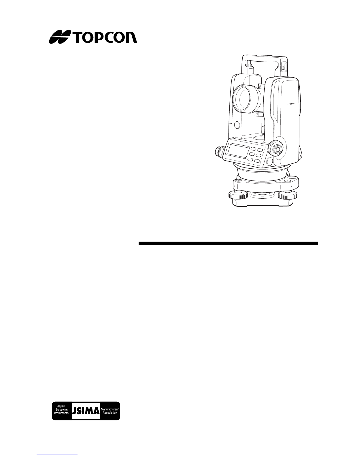
INSTRUCTION MANUAL
DIGITAL THEODOLITE
DT-200/200L
SERIES
Page 2

Page 3

FOREWORD
Thank you for purchasing the TOPCON Digital Theodolite. For the best performance of the instruments, please carefully read these instructions and
keep them in a convenient location for future reference.
1
Page 4

General Handling Precautions
Before starting work or operation, be sure to check that the instrument is
functi onin g correctly w i th normal perf ormance.
Do not submerge the instrument into water.
The instrument can not be submerged underwater.
The instrument is designed based on the International S tanda rd IP66,
therefore it is protected from the normal rainfall.
Setting the instrument on a tripod
When mounti n g the i ns tru me nt on a tripod , use a wooden tri pod when po ssible. The vibr ations th at may occur when usi ng a metallic tripod can effect the
measuring precision.
Installing the tribrach
If the tribrach is installed incorrectly, the me asuring precisi on could be
effe cted . Occasionall y chec k the adjust ing scr ews on the tribrac h. Make sure
the base fix in g lever is locked and the base f ixin g screws are tightened.
Guarding the instrument against shocks
When transpor ting the instrument, provide some protection to minimize risk
of shocks. Heavy shocks may cause the measurement to be faulty.
Carrying the instrument
Always carry the instrum ent by its handgr ip.
Exposing the instrument to extreme heat.
Do not leave the instrument in extreme heat for longer than necessary.
It could adversely affect its performance.
Sudden changes of temperature
Any sud den chang e of temper atu re to the instrument or pris m may resu lt i n a
reduction of measuring distance range, i.e when taking the instrument out
from a heated vehicle. Let instrument acclimate itself to ambient temperature. When a high degree of precision is required for measurement, provide
shade against direct sunlight for the instrument and tripod.
Battery level check
Confirm bat t ery le vel re maining before opera t ing.
Store with the batteries removed, when operation is halted for more than a
month. Leav i ng the batteries att a che d for ext e nded period of time can res ult
in battery leakage, which may lead to malfunctioning.
2
Page 5

Notice on Transceiver
When using high out put transceiver etc. , make sure it does not come near
the instrument.
Opening the carrying case
When opening the carrying case and taking out the instrument, place the
case ho riz ontally, then open the case.
3
Page 6
Display for Safe Use
In order t o encour age the safe use of pro ducts and prevent any danger to the
operat or and oth er s or dam age to properties, importan t warni ng s are put on
the products and inserted in the instruction manuals.
We suggest that everyone understand the meaning of the following displays
and icons before reading the “Safety Cautions” and text
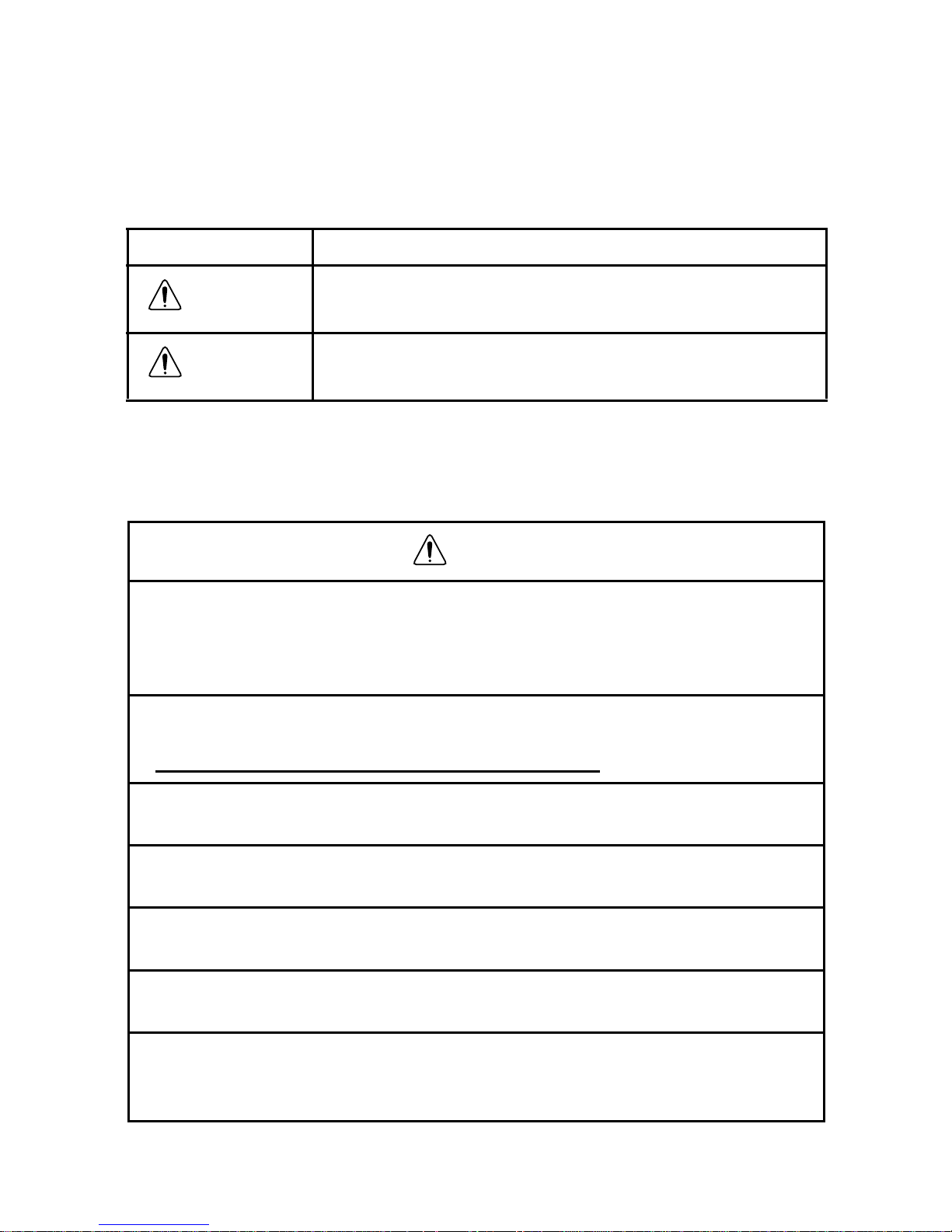
Display Meaning
WARNING
CAUTION
● Injury refe rs to hurt, burn, electric shock, etc.
● Physical damage refers to extensive damage to buildings or equipment and
furniture.
Ignoring or disregard of this display may lead to the
dang er of deat h o r serious injury.
Ignoring or disregard of this display may lead to personal inj ury or ph ysical damage.
Safety Cautions
WARNING
•There i s a risk of f ire, electric shock or phy sical harm if you attempt
to disasse mb le or repair the instru men t y oursel f .
This is only to be carried out by TOPCON or an authorized deale r,
only!
•La ser beams can be danger ous, and ca n cause ey e inju ry's if used
incorrectly.
Never attempt to repair the instrument yourself.
•Cause eye injury or blindness .
Do not stare into beam.
•Cause eye injury or blindness .
Do not look at the sun through a telescope.
•High temperature may cause fire.
Do not connect the batt ery to an instrument while it is charging.
•Risk of fire or electric shock.
Do not use a wet battery or charger.
•M ay ign ite exp l osi vely.
Never use an instrument near flammable gas, liquid matter, and do
not use in a coal mine.
4
Page 7

•Batt ery can cau se ex pl o sion or inj u ry.
Do not dispose in fire or heat.
•Risk of fire or electric shock.
Do not use any po wer v o ltage except th e one given on manufacturers instructions.
•Batt ery can cause outb reak of fire.
Do not block up the vent of the bat tery.
•The short circuit of a battery can cause a fire.
Do not short circuit battery when storing it.
CAUTION
Use of controls or adjustment or performance of procedures other
than those specified herein may result in hazardous radiation exposure.
Do not connect or disconnect equipment with wet hands , you are at
risk of electric shocks if you do!
Risk of injury by overturn the carrying case.
Do not stand or sit on the carrying cases.
Please note that the t ips of tripod can be hazardous , be a ware of th is
when setting up or carrying the tripod.
Risk of injury by falling down the instrument or case.
Do not use a carrying case with a damaged which belts, grips or
latches.
Do not allow skin or clothing to come into contact with acid from the
batteries, if this does occur then wash off with copious amounts of
water and seek medical advice.
A plumb bob can cause an injury to a person if used incorrectly.
It could be dang erous if the instrument falls over, please ensure you
attach a handle to the instrument securely.
Ensure that y ou mount the Tribrac h correctly, f aili ng to do so may re-
sult in injury if the tribrach were to fall over.
It could be dangerous if the instrument falls over, please check that
you fix the instrument to the tripod correctly.
Risk of injury by falling down a tripod and an instrument.
Alw ays c heck t ha t the sc re ws of tri pod are t ig h t ened.
5
Page 8
La s er Sa fe ty
E
DT-205L/207L/209L uses the visible laser beam. DT-205L/207L/209L products are ma nufactured and sold in accordance with “Radiation Safety of
Laser Products, Equipment Classification, Requirements and User‘s Guide”
(IEC Publication 60825-1) or “Performance Standards for Light-Emitting
Products” (FDA/BRH 21 CFR 1040) provided on the safety standards for
laser beam.
As per the said standards, DT-205L/207L/209L classified as “Class 2
(CLASS II) Laser Products”.
The laser bea m belongs not v ery dangerous type b ut we requ est y ou to kee p
and underst and “ Sa fety sta nda r d f or users” as menti o ned in the man ual
instruction.
In case of any failure, do not disassemble the instrument. Contact TOPCON
or your TOPCON dealer.
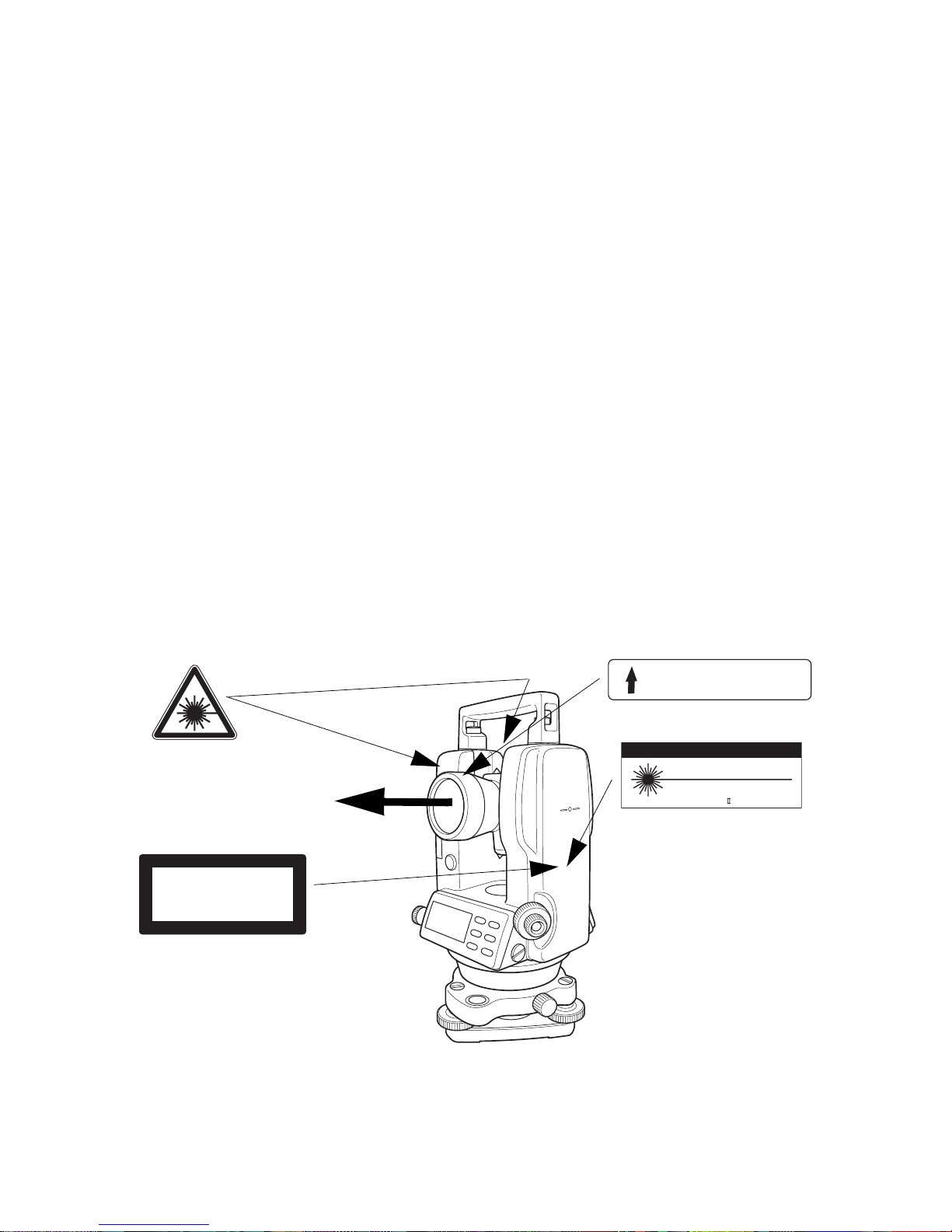
Labels
Find the labels which describes the caution and safety about the laser beam
as follows in DT-205L/ 207 L/209L. We request yo u to repl ace it one an ytim e
the cautio n labels are dama ged or lost and paste a new one at the same
place . You can get the labe ls fr om Topcon or your deale r.
Beam aperture
LASER RADIA TION
DO NOT STARE INTO THE BEAM OF VIEW
DIRECTLY WITH OPTICAL INSTRUMENTS
CLASS 3A @LASER PRODUCT
Depen ding on t he country where the inst rume nt is sold,
either of these labels may be found on the instrument.
AVOID EXPOSUR
LASER LIGHT IS EMITTED
FROM THIS APERTURE
CAUTION
LASER RADIATION
DO NOT STARE INTO BEAM
WAVE LENGTH 633nm
0.6mW MAXIMUM OUTPUT
CLASSII LASER PRODUCTDIODE LASER
6
Page 9

User
1) This product is for professional use only!
The user is required to be a qualified surveyor or have a good knowledge
of surveying, in order to understand the user and safety instructions,
before operating, inspecting or adjusting.
2) Wear the required protectors (safety shoes, helmet, etc.) when operating.
Exceptions from Responsibility
1) The user of this product is expected to follow all operating instructions
and make periodic checks of the product’s performance.
2) The manufacturer, or its representatives, assumes no responsibility for
results of a faulty or intentional usage or misuse including any direct,
indirect, consequential damage, and loss of profits.
3) The manufacturer, or its representatives, assumes no responsibility for
consequential damage, and loss of profits by any disaster, (an earthquake, storms, floods etc.).
A fire, accident, or an act of a third party and/or a usage any other usual
conditions.
4) The manufacturer, or its representatives, assumes no responsibility for
any damage, and loss of profits due to a change of data, loss of data, an
interr uption of b usi ness etc., caused by using the product or an unusable
product.
5) The manufacturer, or its representatives, assumes no responsibility for
any d ama ge, a n d loss of p r ofit s cau sed by u sage except for explained in
the user manual.
6) The manufacturer, or its representatives, assumes no responsibility for
damage caused by wrong movement , o r ac t ion due t o connecti ng wit h
other products .
7
Page 10

Contents
FOREWORD ........................................................................................................1
General Handling Precautions ...................................................................2
Display for Safe Use ..................................................................................4
Safety Cautions .........................................................................................4
Laser Safety ............................................................................................... 6
User ........................................................................................................... 7
Exceptions from Respo nsi bility ................. ................................................. 7
Contents .................................................................................................... 8
Standard Set Composition ......................................................................... 9
1 NOMENCLATURE AND FUNCTIONS .................................................... 10
1.1 Nomenclature.................................................................................... 10
1.2 Display............................................................................................... 14
1.3 Operating keys.............. ........... .......... ................................ ............... 14
2 PREPARATION FOR MEASUREMENT.................................................. 16
2.1 Setting Instrument Up for Measurement ........................................... 16
2.2 Power Switch Key ON....................................................................... 18
2.3 Battery Level Indi cato r....................................................................... 1 9
2.4 Vertical Angle Tilt Correction............................................................. 1 9
2.5 Serial Signal RS-232C Connector..................................................... 19
3 MEASUREMENT...................................................................................... 20
3.1 Measuring Horizontal Angle Right and Vertical Angle....................... 20
3.2 Switching Horizontal Angle Right / Left ............................................. 21
3.3 Measuring fro m the Required Horiz ontal An gle ................................ 2 2
3.4 Vertical Angle % display.................................................................... 2 2
3.5 Repetition Angle Measurement ......................................................... 23
3.6 Stadia Surveying............................................................................... 25
4 HOW TO OPERATE THE LASER....................... .......... .......................... 2 6
5 THE OTHER FUNCTIONS... ........... .................................................... ..... 2 7
5.1 Buzzer Sounding for Horizontal Angle 90° Increments ..................... 27
5.2 Compasses (vertical angle)............................................................... 27
5.3 Auto Cut Off................... ........... .......... ........... .................................... 27
5.4 Setting Minimum Angle Reading....................................................... 27
5.5 Detach / Attach of Tribrach................................................................ 28
6 SELECTING MODE ................................................................................. 29
6.1 Items of the Selecting Mode..... ......................................................... 29
6.2 How to Set the Selecting Modes....................................................... 31
7 HANDLING POWER SOURCE................................................................ 34
7.1 For removing ..................................................................................... 34
7.2 Replace the battery (DB-35).............................................................. 34
7.3 For installing ...................................................................................... 34
8 CHECK AND ADJUSTMENT................................................................... 35
8.1 Checking /Adjusting the Plate Level.................................................. 36
8.2 Checking and Adjusting the Circular Level........................................ 37
8.3 Adjustment of the Vertical Cross-hair................................................ 38
8.4 Collimation of the Inst rument............................................................. 40
8.5 Checking and Adjusting the Optical Plummet Telescope.................. 42
8.6 Adjustment of Vertical Angle 0 Datum............................................... 43
8.7 Adjustment of Laser Beam................................................................ 44
9 STORAGE PRECAUTIONS. ........... ......................................................... 45
10 OPTIONAL ACCESSORIES.................................................................... 4 6
11 ERROR DISPLAY.................................................................................... 47
12 SPECIFICATIONS.................................................................................... 48
8
Page 11
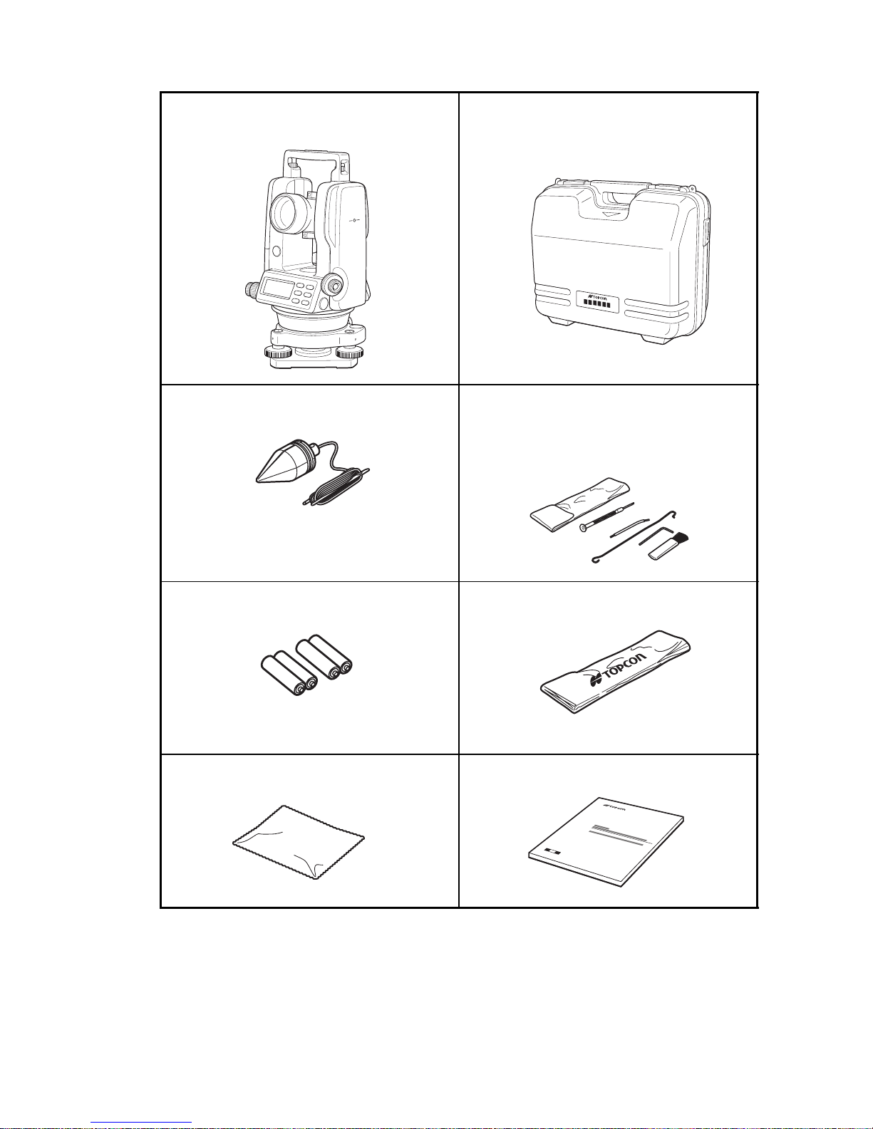
Standard Se t Co mposition
The numerical value in parentheses shows the quantity.
Instrument
(
with lens cap
(1)
Carrying case
)
(1)
Plumb bob set
(1)
Tool kit
Cleaning brush, Screw driver, Rod pins,
Plumb bob hook
(Hexagonal wrench : Only for DT-205/207/209/209P)
(1)
AA batteries (4) Plastic rain cover (1)
Silicon cloth
(1)
Instruction manual (1)
• Make sure that all of the above items ar e with t he ins tru men t when
purchased.
• Guarantee card, Laser use card, Caution sticker are supplied for
certain markets.
9
Page 12
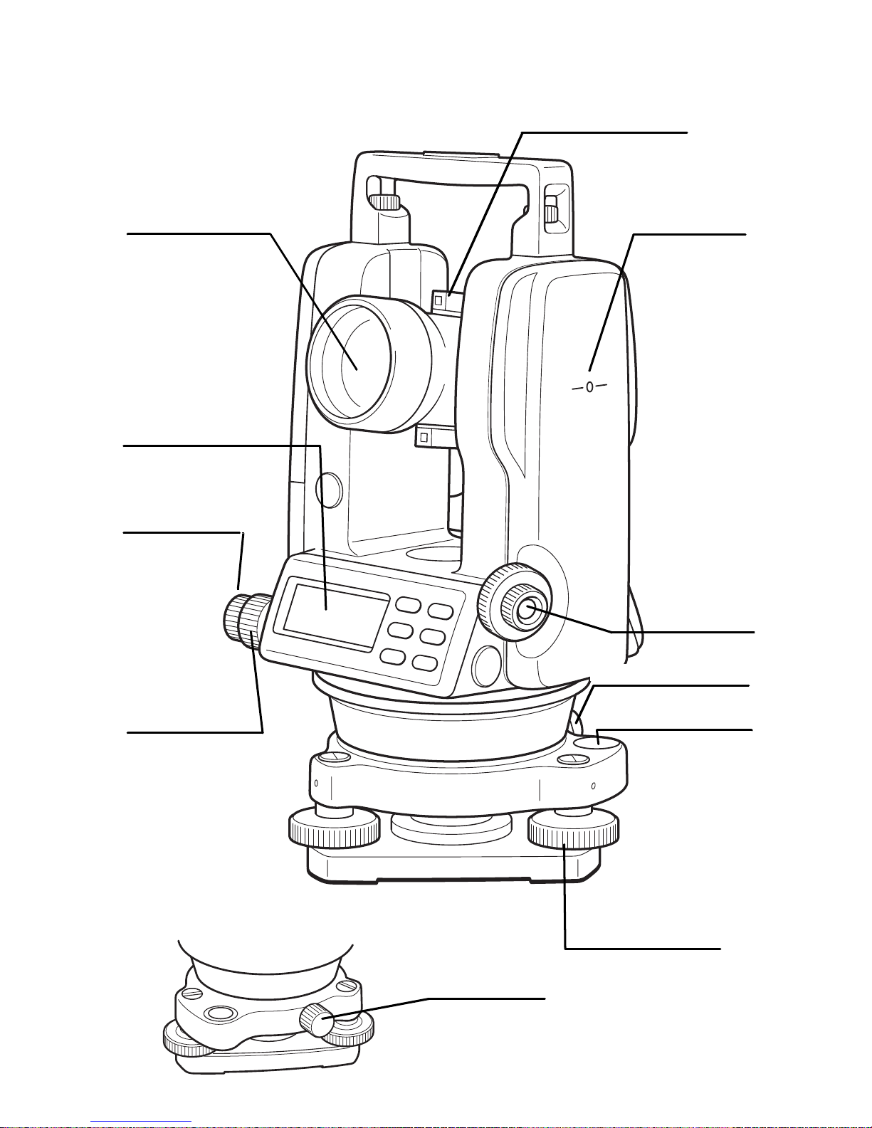
1 NOMENCLATURE AND FUNCTIONS
r
1.1 Nomenclature
DT-205/207/209/209P
Objective lens
Disp la y
window *1)
Horizontal
tangent screw
Sighting collimator
Instrument
height mark
Horizontal
motion clamp
*1) DT-209/209P has one side display only.
Optical
plummet
telescope
Tribrach fixing leve
(2 05 /207 onl y)
Ci rcul ar level
Leveling scr ew
Cent ering scr e w
(209P only)
10
Page 13
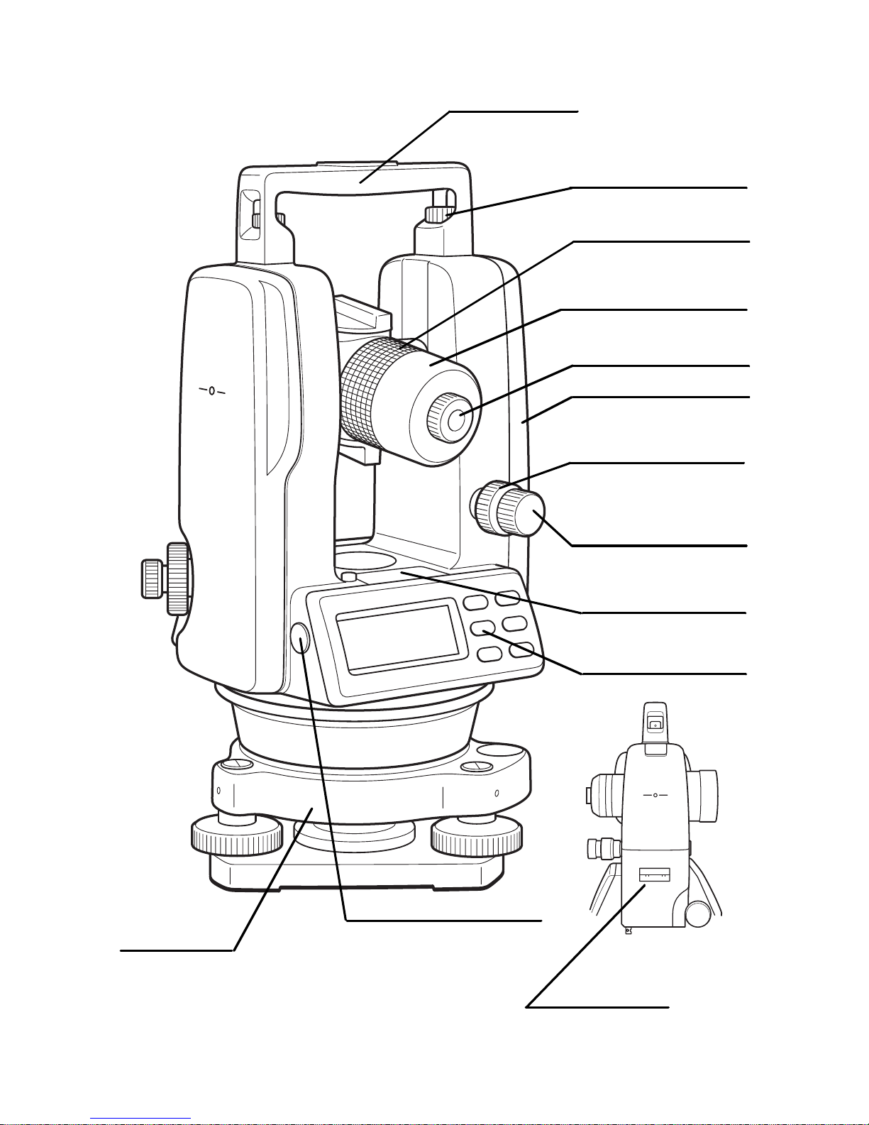
l
t
Handle
t
Handle f ixing knob
Telescope
focusing knob
Cross-hair adjustmen
sec tio n cover
Teles cope eyepiece
Battery
Vertical motion
clamp
Base
RS-232C Con n ector
(205 only)
Vertical tangen
screw
Plate leve
Oper ati on keys
Tribrach type
DT-205/207: Detachable
DT-209: Fixing
DT-209P: Centering
Plate level
(207 onl y)
11
Page 14
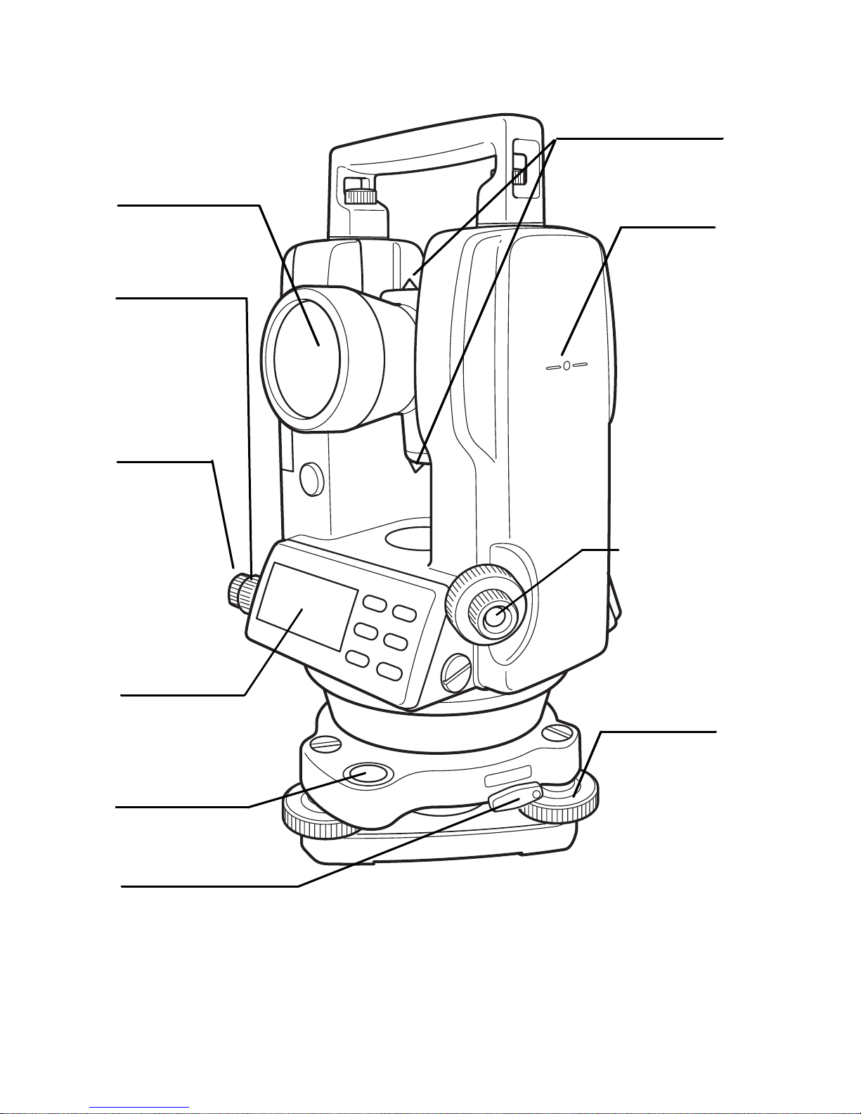
DT-205L/207L/209L
Sighting collimator
Objective lens
Horizontal
motion clam p
Horizontal
tangent screw
Instrument
height mark
Optical
plummet
telescope
Displ ay
window *1)
Circular level
Tribrach fi xing lever
(205L/207L only)
Leveling screw
*1) DT-209L has one side d isp lay only.
12
Page 15
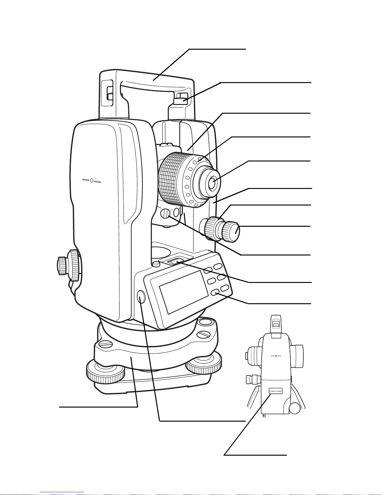
Handle
Handle fixing knob
Telescope
focusing knob
Cross -hai r ad just men t
section cover
Telescope eyepiece
Vertical motion
clamp
Vertical tangent
screw
Battery
Base
Tribrach type
DT-205L/207L: Detachable
DT-209L: Fixing
Laser axis adjusting
screw (with cap)
Plate level
Operation keys
RS-232C Con n ector
(205L only)
Plate le vel
(207L only)
13
Page 16
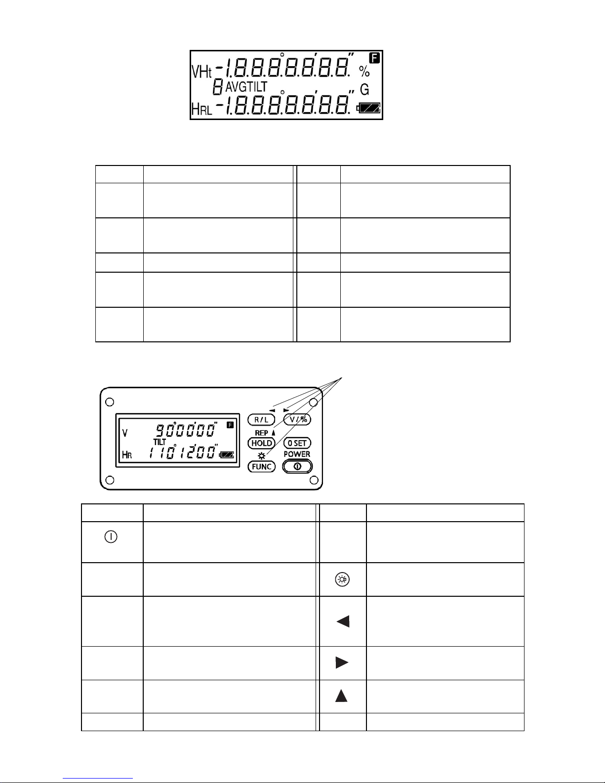
1.2 Display
Display marks
Display Contents Display Contents
V
HR
HL
Ht
Vert i ca l an gl e
Horizontal angle right
Horizontal angle left
Repetition angle measurement
8AVG
The num be r o f repeti tion / Average of an gle
1.3 Operating keys
TILT
F
%
G
Tilt correction mode
(D T-205/20 5L only)
Function key selection
mode
Percent gr ade
Unit disp lay G O N
Function mode
Key Function Key Function (Function mode)
Power switch
R/L
Selection f or horizonta l angle ri ght / le ft meas urem en t
Ver t ic al angle display
V/%
Selection for vertical angle /
percent display
HOLD
0 SET
FUNC
Holdi n g the ho rizo nt al an gl e
Horizont al angle 0° set
Upper function selection
14
REP
Repetiti on angle measurement
Illu mina tion of di sp lay
ON/OFF
Movi ng t h e blin king digi t
to the le ft
Movi ng t h e blin king th e
digit to the right
Increment the blinking
numeral
Page 17

Adjustment mode and Selecting mode
Mode Key
Adjustment mode of vertical angle 0
datum
Selecting mode 1
Selecting mode 2
Turn the power ON while pressing
the [0 S ET] key.
Turn the power ON while pressing
the [R /L] key.
Turn the power ON while pressing
the [V/%] key.
15
Page 18

2 PREPARATION FOR MEASUREMENT
2.1 Setting Instrument Up for Measurement
Setting up the Tripod
First, extend the extension legs to suitable lengths and tighten the screws on
their midsect ions.
Attaching the Instrument on the Tripod Head
Place the inst rumen t caref ully on the tri po d he ad and sl ide the in str ume nt by
loosening the tripod screw. If the plumb bob is positioned right over the center of the point, slightly tighten the tripod screw.
Roughly Leveling the Instrument by Using the Circular Level
1) Turn the leveling screws A and B to move the bubble in the circular level.
The bubble is now located on a line perpendicular to a line running
through the centers of the two leveling screws being adjusted.
2) Turn the leveling screw C to bring the bubble to the center of the circular
level.
Leveling screw C
Leveling screw A
Leveling screw B
16
Page 19

Centering by Using the Plate Level
1) Rotate the instrument horizontally by using the Horizontal motion/clamp
screw and place the plate level par al l el with the line connect ing lev el ing
scre w s A and B, and then bring the b ub b l e to the center of the plate l evel
by turning le velin g screws A and B.
Leveling screw A
Leveling screw B
2) Rotate the instrument 90° (100g) around its vertical axis and turn the
remaining leveling screw or C to center the bubble once more.
Leveling screw C
3) Repe at th e pr ocedures 1 and 2 f or each 90° (100g) r otation of the
instrum ent and che c k whet her t he b ub ble is corre ct ly centere d f or al l four
points.
Centering by Using the Optical Plummet Telescope
Adjust the eyepiece of the optical plummet telescope to your eyesight.
Slide the instrument by loosening the tripod screw, place the point on the
center mark, and then tighten the tripod screw. Sliding the instrument carefully not to rotat e that allows yo u to get the l east dislocation of the bubble
Complet el y Leveling the Instrument
Lev elin g the i nstrument precisely i n a similar w ay to 4. Rotate the instrument
and chec k to see that the bu bbl e is i n the center of the pl a t e l e v e l regar dl es s
of telescope direction, then tighten the tripod screw hard.
17
Page 20

2.2 Power Switch Key ON
1
Confirm the instrument is leveled.
2
Turn the power switch ON.
Every segment turns on for about 1 second.
HR 342°03’41”
3
Press the [V/%] key . The vertical angle is displayed.
Battery Power
Remaining Display
V 11°50’28”
HR 342°03’41”
● Confirm the battery power remaining on the display. Replace with charged
bat tery o r ch ar ge w h en battery le v el is l ow. Ref er to S ec ti on 2.3 “Bat tery L e v el Indicator” .
18
Page 21

2.3 Battery Level Indicator
The battery power indicator shows the level of battery strength.
V 90°10’20”
TILT
HR 123°40’50”
Measurement is po ssibl e.
Battery Power
Remaining Display
Measurement is im possible.
Need to recharge or replace the
battery.
1) The bat tery operati ng time will vary depen di ng on the environ mental
conditions, such as ambient temperature etc. It is recommended for
safety to prepare spare batteries.
2) For general usage of battery, see chapter 7 “HANDLING POWER
SOURCE”
2.4 Vertical Angle Tilt Correction
(DT-205/205L only)
When the tilt sensor is activated, automatic correction of vertical angle for
mislevelment is displayed. To ensure a precise angle measurement, tilt sensors must be turned on. If the "b" display appears the inst ru ment is out of
automatic compensation range and must be leveled manually.
V 90°10’20”
TILT
HR 123°40’50”
In case the instrument is used in an unstable situation, constant indexing of
vertical angle ma y be impossib le . In this cas e , the fun ctio n of tilt corr ecti on
can be stopped.
To stop the function of til t corr ec t ion, refer to Chapt er 6 “SELEC TIN G
MODE”.
2.5 Serial Signal RS-232C Connect or
(DT-205/205L only)
Serial signal c onnecto r is used fo r co nnecting the DT-205/205L with a com puter, whi ch enables the computer to receive measurement data fr om the
DT-205/205L.
Out of the tilt
correc t ion range
19
V b
TILT
HR 123°40’50”
Page 22

3 MEASUREMENT
3.1 Measuring Horizontal Angle Right and Vertical Angle
1
Collimate the first target "A".
V 90°10’20”
HR 120°30’40”
2
Press the [0 SET] key twice to set the horizontal angle of target "A"
°
at 0
00' 00".
V 90°10’20”
HR 0°00’00”
• One time pressing [0 SET] function is available. Refer to "6
SELE CT I NG MODE" .
3
Collimate the second target "B".
The required H/V angle to target B will be displayed.
V 92°10’20”
HR 160°40’20”
20
Page 23

3.2 Switching Horizontal Angle Right / Left
1
Collimate the first target "A".
V 90°10’20”
HR 120°30’40”
2
Press the [R/L] key.
The mode Horizontal angle right (HR) switches to Horizontal angle
left (HL)
V 90°10’20”
H L 239°29’20”
• Every time pressing the [R/L] ke y, HR/HL mode switches.
3
Measu re as HR mode .
Reference : How to Collimate
1
P oi nt the t ele scope tow ar d the li g ht. Turn the diopt er rin g and adju s t
the diopter so that the cross hairs are clearly observed.
(Turn the diopter ring toward you first and then backward to focus.)
2
Aim the target at the peak of the triangle mark of the sighting
colli mator . All ow a ce rtain space be tween the sig hting col li mator an d
yourself for collimating.
3
Focus the target with
the focusing knob.
*If parallax is created
betw een the cross hairs
and the target when
viewing v e rtically or
horizontally while looking
into the telescope,
fo cus i ng is incorrect or
diopter adjustment is
poor.
Eye
Focusing knob
Telescope eyepiece
(Diopter ring)
This adversely affects precision in measurement or survey.
Eliminate the par all a x by care f ull y f ocusi ng and usin g diop t er
adjustment.
21
Page 24

3.3 Measuring from the Required Horizontal Angle
1
Display the r equire d hori zontal angle us ing the horizon tal motion
clamp and horizontal tangent screw.
V 90°10’20”
HR 130°40’20”
2
Press the [HOLD] key.
The displa y of horizontal angle blinks and the horizontal angle will
be held.
V 90°10’20”
HR 130°40’20”
• To return to the ang l e stat us befor e the data is held, press any key
exce pt the [HOLD] key.
3
Collimate the target to set.
4
Press the [HOLD] key. The angle measurement will start from the
held angle.
V 90°10’20”
HR 130°40’20”
3.4 Vertical Angle % display
V 66°23’10”
blinks
1
Press the [V/%] key.
• Every time pressing the [V/%] key, the mode sw itch es .
When th e me asur eme nt i s carr i ed out over t han 45° fro m the
ho rizonta l, the di splay sho ws [ --------].
HR 120°30’40”
V 43.719%
HR 120°30’40”
22
Page 25

3.5 Repetition Angle Measurement
1
Press the [FUNC] key.
F
V 90°10’20”
HR 120°30’40”
2
Press the [REP] key.
Ht 0°00’00”
0
H
3
Collimate the target "A", and press the [0SET] key twice.
Ht 0°00’00”
0
H
4
Collimate the target "B", and press the [HOLD] key.
Ht 45°10’00”
1AVG
H 45°10’00”
5
Recollimate the target "A" and press the [R/L] k ey.
6
Recollimate the target "B", and press th e [HOLD] key.
Total angle
Ht 90°20’00”
2AVG
H 45°10’00”
The number of measurements A verage of angl e
2 measurements
23
Page 26

7
Repeat the procedure 5 and 6 to measure the desired number of
repetition.
Ht 180°40’00”
4AVG
H 45°10’00”
Exampl e: 4 meas urem ents
8
To finish the repet i tion measurement, pr ess the [FU NC] key and
press the [HOLD] key.
• Horizontal angle can be accumulated up to
(2000°00'00" – minimum reading) (horizontal angle right).
In case of 5 second reading, horizontal angle can be
accumulated up to +1999°59'55".
• When the discrepancy value of each measuring is more than
±30", the error code “E04” is displayed. Press the [0S ET] key,
and measure from the beginning.
• Maximum 19 measurements are available.
The 10th or more repetition measurements, the figure of 10th
digit will be omitted.
24
Page 27

3.6 Stadia Surveying
S
This instrument can be used for stadia surveying, Measurement by stadia is
a convenient method for measuring distances with the stadia hairs of the
instrument, in combination wi th a gradua ted rod, such a s a leveling rod o r
stadia rod, which is preferable fo r long distances. The distance from the center of the instrument to the rod is found by sighting through the i nstrument on
the rod and multiplying the stadia interval by 100. The stadia interval is the
distance between the to p stadi a hair r eading and the bott om stadia fai r read ing.
tadia hair s
d
D=100 × d
1
Set the rod on the point to be surveyed.
2
Sight through the telescope of the leveled instrument and determine
the distance or interval, “ d ”, between the top stadia hair reading
and bottom stadia hair reading of the rod.
3
The horizon tal distance “ D ” from the cen ter of the instrument to the
rod is equal to 100 times the stadia inte rv al, “ d ”.
D=100 × d
d
25
Page 28

4 HOW TO OPERATE THE LASER
(DT-205L/207L/209L only)
WARNING
Aiming the instrument into prism or highly reflective surface can result in se rious damage to your eye because the
opt ical axis and laser beam sou rce is in coincidence.
Do not aim the instrument directly into prism or highly re fle cti ve sur face.
Do not look at the laser beam directly.
•Laser beams can be dangerous, and can cause eye injury's
if used incorrectly.
Never attempt to repair the instrument yourself.
1
Co ll i mate a tar get.
2
Press the laser power
switch.
The laser beam will
emit and the green
lam p wil l illumin ate.
Green l am p
DT-205L/207L/209L are so designed as to provide the telescope and
laser beam with simultaneous focussing to give the minimum spot.
ON/OFF
Laser power
switch
26
Page 29

5 THE OTHER FUNCTIONS
5.1 Buzzer Sounding for Horizontal Angle 90° Increments
When the horizontal angle f alls in the range of l ess than ± 1° o f 0°, 90°, 180°
or 270°, the buzzer sounds. Buzzer stops only when the horizontal angle is
adjusted to 0°00’00”, 90° 00 ’ 00” , 180° 00 ’ 00” or 27 0 ° 00’0 0 ”.
To stop the buzzer sounding, refer to "6 SELECTING MODE" .
5.2 Co mpasses (vertical angle)
Ve rtical angl e scale is di splayed as shown below.
To set this function, refer to "6 SELECTING MODE".
°
+90
°
0
-90°
0°
5.3 Auto Cut Off
If no key operation is given for more than 10 or 30 minutes, the power turns
off automatically.
To set this function, refer to "6 SELECTING MODE".
5.4 Setting Minimum Angle Reading
Selec t minimum di splay unit for angle measurement. It is possible t o select it
as shown below.
To set this function, refer to "6 SELECTING MODE".
DT-205/205L 1" / 5" (0.5 mgon / 1 mgon)
DT-207/207L 5" / 10" (1 mgon / 2 mgon)
DT-209/209P/209L 10" / 20" (2 mgon / 5 mgon)
27
Page 30

5.5 Detach / Attach of Tribrach
Only for detachable tribrach type
Securing screw
Alignment piece
Tribrach alignment
groove
Tribrach fi xi ng lever
The inst rumen t is easi ly detac hed or attached to the tribrach, with a tribr ach
locking lever loosened or tightened for this purpose.
● Detachment
1
Loosen the tribrach locking lever, by revolving it 180° or 200g in the
counterclockwise direction (which will point the triangle mark
upwards).
2
Grip the carrying handle firmly with one hand while holding the
tribrach with the other. Then lift the instrument straight upwards and
off.
● Attachment
1
Hold the ins tru me nt by the car rying handle , wit h one hand , and
carefully lower it on top of the tribrach while, at the same time,
coinciding th e a l ignm en t piece w i th the t ribr a ch a l ignment groove on
the instrument and tribrach respect iv ely.
2
When fully seated, revolv e the t ri brach loc king lever 180° or 200 g
clockwise ( which will point the triangle mark downwards again).
● Locking the Tribrach Locking Lever
The tribrach locking lever can be locked, to prevent it be accidentally
removed, especially if the upper instrument section is not being detached
very ofte n. Si mply tighten t he securi ng scr ew on t he locking lever with the
ac cessor y screwdr iver, fo un d in the case .
28
Page 31

6 SELECTING MODE
The following modes are available
6.1 Items of the Selectin g Mode
Selecting mode 1
To set the instrument the selecting mode 1, turn the power ON while pressing the [R/L] key.
Selecting mode 1
[R/L] key + Power on
0 0 0 0 0 0 0
Digit No.1Digit No.7
Selecting mode 1
Digit
No.
1
2
3
4
Items Contents Setting value
Minimum
angle unit
V angle
Z0 / H0
Select the minimum angle
unit.
Select the vertical angle
reading from zen ith o r fr om
(DT-205/205L)
(DT-207/207L)
(DT-209/209P/
209L)
Horizontal 0 Zenith 0
horizontal.
Auto cut off
ON/OFF
Set the function of power
off automatically when no
key operation is continued
10 or 30 minutes.
Auto cut off
time 10 m in.
Set the interval time of
power off automatically.
10 mi n. 30 min.
/ 30 min.
Setting
= 0
5"
10"
20"
value = 1
1"
5"
10"
ON OFF
5
Angle unit
DEG/GON
6
90° buzzer
ON/OFF
7
Angle unit
MIL
Choose degre e (DEG), gon
DEG GON
(GON).
Specify w hether the buzz er
ON OFF
sounds o r not f or e v ery horizontal 90°
Choose angle unit MIL. DEG /GON MIL
29
Page 32

Selecting mode 2
To set the instrument the selecting mode 2, turn the power ON while pressing the [V/%] key.
Selecting mode 2
[V/%] key + Power on
0 0 0 0 0 0 0
Digit No.1Digit No.7
Selecting mode 2
Digit
No.
1
2
3
4
5
6
7
Items Contents Setting
[0 SET] key
pressing
Choose once or t wi ce for pre ssing the [0 SET] key.
once / twice
Compass
ON/OFF
RS-232
Output *1)
H Angle
Memory
Set the function of compass
(Ver tical angle scale).
Set the function of sending the
me asured data .
Horizontal angle set can be retained after the power is turned
off.
Tilt
correction
Set the function of the tilt correction.
ON/OFF *1)
Unused
---
Setting
value = 0
value = 1
Twice Once
OFF ON
OFF ON
OFF ON
OFF ON
--- ---
• Do not cha nge the set ting value (0) of unu sed items.
• *1)DT-205/205L only
30
Page 33

6.2 How to Set the Selecting Modes
● Selecting Mode 1
Sample setting: Auto cut off : OFF, 90
1
Turn the power ON while pressing the [R/L] key.
The instrument will be in the selecting mode 1, and the digit No.1
will blink.
0 0 0 0 0 0 0
2
Let the digit No.3 to be set blink by pressing the [ ] key.
0 0 0 0 0 0 0
° buzzer : OFF
Digit No.1Digi t No.7
Blinking
Blinking
● Pressing t h e [ ] key, bli nking digit moves to the right.
3
Press the [ ] key to set 1 for the digit.
0 0 0 0 1 0 0
● Every time pressing the [ ] key, the blinking digit value 0/1 switches.
4
Let the digit No.6 (90° buzzer) to be set blink by pressing the [ ]
key.
0 0 0 0 1 0 0
Blinking
5
Press the [ ] key to set 1 for the digit.
0 1 0 0 1 0 0
31
Page 34

6
Press the [0 SET] key to set the setting.
S E T
0 1 0 0 1 0 0
7
Turn the po wer off.
32
Page 35

● Selecting mode 2
Sample setting: [0 SET] key pressing : Once, Tilt correction
1
Turn the power ON while pressing the [V/%] key.
The instrument will be in the selecting mode 2, and the digit No.1
( 0set key pressing) will blink
0 0 1 0 0 0 0
2
Press the [ ] key to set 1 for the digit.
0 0 1 0 0 0 1
● Every time pressing the [ ] key, the blinking digit value 0/1 switches.
.
Blinking
: OFF
3
Let the digit No.4 (Tilt correction) to be set blink by pressing the
] key.
[
0 0 1 0 0 0 1
Blinking
● Pressing t h e [ ] key, bli nking digit moves to the right.
4
Press the [ ]key to set 0 for the digit.
0 0 0 0 0 0 1
5
Press the [0 SET] key to set the setting.
6
Turn the po wer off.
S E T
0 0 0 0 0 0 1
33
Page 36

7 HANDLING POWER SOURCE
7.1 For re moving
1
Push the lock le ver downw ar d and pull out t he batt ery.
Lock lever
7.2 Rep la ce the battery (DB-35)
Lid
Hook
1
Push the hook downward and take the lid out.
2
Take out the old batteries and put new batteries as illustratio n shows
in direction of plus and minus sides
3
Insert a convex in a upper hole. Click to close the lid by pressing it.
● Replace all four batteries to new ones at the same time.
● Do not mix the old batteries to the new on es.
Hole
Lid
Convex
7.3 For installing
Place the base of the b attery into the main bod y, push the b at tery tow ard the
instrument side till the battery clicks into position .
34
Page 37

8 CHECK AND ADJUSTMENT
● Pointers on the Adjustment
1
Adjust the eyepiece of the telescope properly prior to any checking
operation which involves sighting through the telescope.
Remember t o f ocus properly, with parallax completely eliminated.
2
Carry out the adjustments in the order of item numbers, as the
adjustm ent s a re dependent one upo n ano t her. Adjust men ts carried
out in the wrong sequence may e ven nu llify previous adjustment.
3
Always conclude adjustments by tightening the adjustment screws
securely (but do not tighten them more than necessary, as you may
strip the threads, twist off the screw or place undue stress on the
parts).
Furthermore, always tighten by revolving in the direction of
tightening tension.
4
The atta chm ent scr e ws mu st also be t ight e ned suffi ciently, upon
comple ti on of adjustment s .
5
Always repeat checking operations after adjustments are made, in
order to confirm results.
● Notes on the Tribrach
1
If any lev elin g screw becomes loose and slack or if collimation is
unstable due to the looseness of leveling screws, adjust by
tightening the adjusting screws (in 2 places) installed over each
leveling screw with a screwdriver
2
If there is an y slack between the l evelin g scr ews an d the base,
loosen the set s crew of t he hol ding ring and t ighten t he holdi ng ring
with adjusting pin, until it is properly adjusted. Re-tighten the set
scre w on completing the adjustment
Adjustment
screw
Adjustment
screw
Leveling
screw
Holding ring Se t screw
35
Page 38

8.1 Checking /Adjusting the Plate Level
Adjus tment is required if the axis of the pl ate level is not perpendicular to the
vertical axis.
●
Check
1
2
ing
Place the pl ate lev el par allel to a l i ne runnin g thr ough the cen t ers of
two leveling screws, say, A and B. Use these two leveling screws
on l y and plac e the bubble i n the cent er of t he plate level.
Rotate the instr ument 180° or 200g arou nd the v ertica l axis and
ch eck bub ble mo vem ent of the plate level. If the bubble has been
displaced, then pr oceed with the f ollo wi ng adjus tme n t.
Plate level
Leveling scr ew A
● Adjustment
1
Adjust the level adjustment capstan screw, with the accessory
adjusting pin and return the bubble towards the cen t er of the p late
level. Correct only one-half of the displacement by this method.
2
Correct the remaining amount of the bubble displacement wi th the
leveling screws.
3
Rotate the instr ument 180° or 200g arou nd the v ertica l axis once
more a nd check bubbl e movem ent. If the bubble is still displaced,
then repeat the adjustme nt.
Level adjustment
capstan screw
Leveling screw B
Half amount of displacement
36
Page 39

8.2 Checking and A djusting the Ci rc ular Level
● Checking
1
Carefully level the instrum ent with the plat e level only. If the bubble
of the circular level is centered properly, adjustment is not required.
Otherwise, proceed with the following adjustment.
● Adjustment
1
Shift t he bubble to the center of the circular level, by adjusting three
capstan adjustment screws on the bottom surface of the circular
level, with the accessory adjust ing pin.
Caps tan adju stment scre ws
Bottom of the base
37
Page 40

8.3 Adjustm ent of the Vertical Cross-hair
Adjustment is required if the vertical cross-hair is not in a place perpendicular to the ho riz ontal axis of t he te l escope ( si nce it mus t be possib le to use
any point on the hair for measuring horizontal angles or running lines).
● Checking
1
Set the instrument up the tripod and carefully level it.
2
Sight the cross-hairs on a well defined Point A at a distance of, at
least, 50 meters (160ft.) and clamp horizontal motion.
3
Next swing the telescope vertically using the ver tical tangent screw,
and check whether the point travels along the length of the vertical
cross-hair.
4
If the point appears to move continuously on the hair, the vertical
cr o ss-hair lies in a plane perpen dic ula r to the h o rizontal axi s ( and
adjustment is not required ).
5
However, if the point appears to be displaced from the vertical
cross-hair, as the telescope is swung vertically, then proceed with
the fol l ow i ng adjustment.
● Adjustment
1
Unscrew the cross-hair adjustment section cover, by revolving it in
the counterclockwise direction, and take it off. This will expose four
ey epiece section att achment screws.
2
Loosen a ll fou r attachment scre w s sli g htl y w it h th e accessory sc re wdrive (while taking note of the number of revolutions).
Then revolve the eyepiece section so that the vertical cross-hair
coincides to Point A’.
Finally, re-tighten the four screws by the amount that they were
loosened.
38
Page 41

3
Ch eck once more and i f the point travels the e nti re lengt h of th e
vertical cross-hair, fur ther adjustment is not required.
Ey epie ce section
attachment screws
Eyepiece
Perform following adjustment after completing the above adjustment .
Section 8.4 “Collimation of the Instrument”, Section 8.6 “Adjustment of Vertical Angle 0 Datum”.
39
Page 42

8.4 Collimatio n of the Instru ment
Eyepiece
Collimation is required to make the line of sight of the telescope perpendicular to the horizontal axis of the instrument, otherwise, it will not be possible to
ext end a st raight line by dir ect me ans.
●
Check
1
2
3
4
ing
Set th e i nstrument up w ith
clear s i ghts of about 50 to
60meters
(160 to 200 ft.) on both
sides of the instrument.
Level the instrument
properly with the plate
level.
Sight Point A at
appro x i ma tel y 50 mete rs
(160 ft.) dist anc e.
Loosen the v ertica l
motion clam p only, and
rotate the telescope 180°
or 200g around the
horizon tal axis , so that the
telescope is pointed in the
opposite dir ecti on.
50
Telescope
50
50
5
Sight Point B, at equal
distance as Point A and
tight en the v ertical motion
clamp.
6
Loosen the horizont al
motion clamp and rotate
the instrument 180 ° or
20 0g around t he ver t ical
axis. Fix a sight on Point
A once more and tighten
the horiz ont al motio n
clamp.
7
Loosen the v ertica l
motion clam p only and
rotate the telescope 180°
or 200g aro und the hori z ontal axis once mo re and fix a sight on
Point C, which should coincide with previous Point B.
8
If Points B and C do not coincide, adjust in the following manner.
50
40
Page 43

Adjustmen
nt
●
1
2
3
t
Unscrew t he cross-hair
adjustment section cover.
Find Point D at a point
between Points C and B,
which should
be equal to 1/4th the
distance between Poi nts
B and C and measured
from Point C. This is
because t he apparent
error between Points B
and C is f our times t he actual err or sin ce
the telescope has been reversed twice during the checking
operation.
Shift the vertical
cross-hair line and
coincide it with
Point D, by revolving
the left and right
capstan adjust m ent
screws with the
hexagonal wrench*
(or adjust ing pin).
Up on completi ng the
adjustm ent , r ep eat
the chec ki ng
opera ti on once mo re .
If Points B and C coincide, further adjustment is not required.
Capstan
adjustment
screw
*DT- 205/207/209/209P : Hexagonal wrench
DT- 205L/207L/209L : Adjusting pin
Capstan
adjustme
screw
Eyepiece
Otherwise, repeat the adjustment.
● First, loosen the capstan adjustment screw on the side to
which the v ertical cross-hai r line must be mov ed. Then tight en
the adjustment screw on the opposite side by an e q ual
amount which wil l leave the tens ion of the adjustment screws
unchanged.
Re volv e in the countercl ockwise direction t o loosen an d in the
clockwise direction to tighten, but revolve as little as possible.
● Perform following adjustment after completing above adjustment . Section 8.6 “Adjustment of Ver t ical Angle 0 Datum”.
41
Page 44

8.5 Checking and Adjusting the Optical Plummet T elescope
Adjustment is required to make the line of sight of the optical plummet telescope coin cide with the ve rtical axis ( otherwise the v ertical axis wil l not be in
the true vertical when the instrument is optically plumbed).
Check
●
1
2
● Adjustment
1
ing
Coincid e the ce nt er ma rk and the poin t . (See Cha pter 2
“PREPARATION FOR MEASUREMENT” .)
Rotate the instr ument 180° or 200g arou nd the v ertica l axis and
check the center mark.
If the point is properly centered in the center mark, adjustment is not
required. Otherwise, adjust in the following manner.
Take off the ad justmen t sect ion cover of the optical plummet
telescope eyepiece. This will expose four capstan adjustment
scre ws which sho uld be adj usted wi th the acces sory adjustin g pin to
shift the center mark to the point. However, correct only one-half of
the displ ace men t in this ma nner.
Capstan
adjustment
screws
2
Use the leveling screws and coincide the point and center mark.
3
Rotate the instr ument 180° or 200g arou nd the v ertica l axis once
more and check the center mark. If it is coincided to the point, then
further adjustment is not required. Otherwise, repeat the
adjustment.
First, loosen the capstan adjustment screw on the side to
Eyepiece
Plum met tel e sco pe
Capstan
adjustment
screws
1/2 of
displacement
which the center mark must be moved. Then tighten the adjustment screw on t he opposite side b y an equal amount which
will leave the tension of the adjustment screws unchan ged.
Re vol v e in th e counter cloc kwi se dir ection to loosen and in the
clockwise direction to tighten, but revolve as little as possible.
42
Page 45

8.6 Adjustm ent of Vertical Angle 0 Datum
If when measuring t he ve rtical angl e of targ et A at tele scope pos iti on normal
(direct) and reverse settings, the amount of normal and reverse measurements combined is other than 360° (ZENITH-0), half of the difference from
360° is the error amount from corrected 0 setting. Carry out adjustment. As
adjustment for vertical angle 0 setting is the criteria for determining instrument coordinate origin, use special care for adjustment.
1
Level the instrument properly with the plate level.
2
While press i ng the [0 SE T]key, turn powe r swi t ch ON.
V STEP-1
3
Collimate target A from the telescope properly in normal setting.
4
Press the [0SET] key.
V STEP-2
5
Collimate target A in reverse telescope setting.
6
Press the [0SET]key.
Measured value is set and carry out normal angle measurement.
SET
7
Turn the po wer switch off.
● Any misoperat ing and error code displa y appears. Repeat the
above procedure from the start.
● Check that the total amount of normal and reverse angular
tra v el is 360°
positions.
collimat ing the target A by normal and re ve rse
43
Page 46

8.7 Ad justm ent of Laser Beam
B
This adjustment must be done after completing following checking and
adjusting. 8.3 “Adjustment of the Vertical Cross-hair”, 8.4 “Collimation of the
Instrument”.
WARNING
● Aiming the instrument int o prism or highly reflecti ve sur f ace can result in serious damage to your eye because the optical axis and laser beam source is in coincidence.
Do not aim t he instrument directly i nto prism or highly re flectiv e surface.
Do not look at the laser beam directly.
In i nterse cti on of the cross-hair does not coincide with the lase r spot , turn the
laser axis adjusting screws to move the laser spot to coincide with intersection of the cross -hair.
1
Remove the caps of the laser axis adjusting screws with coin.
As shown below, the screws are called A and B.
Laser axis adj u sti n g scre w B
Laser axis adjusting screw A
2
Following shows the moving direction of the laser spot by turning the
laser adjusting screws.
Turn screw A
counterclockwise
Turn screw A
clockwise
3
Attach the caps of the laser axis adjusting screws.
Laser spot
Turn screw B
counterclockwise
Laser spot
Turn screw
clockwise
44
Page 47

9 STORAGE PREC AUTIONS
● Whe n re tur ning t h e in stru ment to its ca se, be s ure to ma t c h the wh it e position in g mark s p rovided wit h th e ca se and place the inst ru ment wit h the eyepie ce upwa r d .
● For cleaning the instrument after use, remove dust using a cleaning brush,
then w ipe off wit h a cloth .
● For cleaning the lens surface, use a cleaning brush to remove the dust, then
use a clean lintless cotton cloth. Moisten it with alcohol (or mixture with ether)
to wipe gently in a rotational motion from the center out.
● To remove the dust on the case, never us e thinner o r benzine. Use a clean
clo th mo is tened w ith ne u tral detergent.
● Check e ac h par t of t h e tripod after exte n de d us e. Par t s (s c rew s or cla mps)
may work themselves free.
45
Page 48

10 OPTIONAL ACCE SSORIES
Diagonal Eyepiece, M odel 13
The diagonal eyepiece is used in place of the telescope eyepiece for making
observations up to the zenith.
Instrument eyepiece
Diagonal eyepiece,
model 13
Trough Compass model 5
The trough compass i s simply mounted on top of the carrying ha ndl e.
Ba ck pack
When t ransport i ng the ins tru men t with th i s back pack, it is very convenient
for carry ing the i nstrum ent on the shou lder. This soft case with aluminum
frame is compact and light, yet, is highly shockproof and rainproof.
Aluminum extension leg tripod
Wide frame extension leg tripod (wood)
46
Page 49

11 ERROR DISPLAY
Display Contents Countermeas ure
AnGLE
Error
E04
E70
Displayed when the instrument or the telescope rotated
quickly.
Displayed when the discrepancy value of each measuring
is more than ±30” while repetiti on an g le me as ure men t i s op erated.
When "Adjustment of Vertic al
Angle 0 da t u m " is adju s ted in
wrong procedure.
or
When "Adjustmlent of Vertical
Angle 0 datum " is ca r ried out
to the range out of ±45° from
the horizontal.
In this ca se, i t i s not failure.
However, repair is required when
"AnGLE Error" is displayed frequently.
Press th e [0SET ] ke y, measure
again from the beginning.
Switch off the power, then on again.
Confirm the procedure and adjust
again.
E99
Abnormality in internal memory system while "Adjustment
of Vertical Angle 0 Datum" is
op erated, or hori zontal an g l e
is set zero or hold.
Switch off the power, then on again.
Confirm the procedure and adjust
again.
• If errors still persist after attempting to clear them, contact your dealer or
TOPCON.
47
Page 50

12 SPECIFICATIONS
(DT-2 0 5/207/209/209P)
Item Item
Telescope Length 149mm 149mm 149mm
Objective lens 45mm 45mm 40mm
Magnification 30× 30× 26×
Image Erect Erect Erect
Field of vi ew 1° 30' 1° 30' 1° 30'
Resolving power 2.5" 2.5" 3"
Minimum focus 0.9m 0.9m 0.9m
Stadia ratio 100 100 100
Stadia constant 0 0 0
Electronic Angle Mea-
surement
Display Unit 2 sides 2 sides 1 sides
Illumination Display Yes Yes Yes
Compensator Tilt sensor Automatic
Optical
Plummet
Telescope
Level
Sensitivity
Water protection Standard IP 66 IP 66 IP 66
Power Supply Battery 4 AA
Operating Time
(Al kali ne ma nganes e
dry batteries),
(+20°C [+68°F]Åj
Tribrach Type Detachable Detachable Fixing: DT-209
Method Absolute Absolute Absolute
Detecting Horizontal :
Minimum reading 1"/5"
Accuracy *1) 5" 7" 9"
Diameter circle 71mm 71mm 71mm
Reticle Yes Yes No
Compensating
range
Magnification 3x 3x 3x
Filed of view 3° 3° 3°
Focusing 0.5m~∞ 0.5m~∞ 0.5m~∞
Plate level 40"/2 mm 40"/2 mm 60"/2 mm
Circular level 10'/2mm 10'/2mm 10'/2mm
Theodolite only Approx. 140
Model
DT-205 DT-207
Horizontal :
2 sides
Vertical :
1 side
(0.5mgon/1mgon)
vertical
compensator
± 3' No No
batteries
hours
2 sides
Vertical :
1 side
5"/10"
(1mgon/2mgon)
No No
4 AA
batteries
Approx. 150
hours
DT-209/
209P
Horizontal :
1 sides
Vertical :
1 side
10"/20"
(2mgon/5mgon)
4 AA
batteries
Approx. 170
hours
Centering:
DT-209P
48
Page 51

Item Item
Others Dimension
DxWxH(mm)
Weight (Includ-
ing batteries)
Instrument height 176 mm
Serial signal
RS-232C
connector
*1) Standard deviation based on DIN 18723
(DT-205L/207L/209L)
Model
DT-205 DT-207
149x188x313
(5.87x7.1x12.3 in)
4.1kg
(9.0 lb)
(6.93 in)
Yes No No
149x188x313
(5.87x7.1x12.3 in)
4.1kg
(9.0 lb)
176 mm
(6.93 in)
DT-209/
209P
DT-209:
149x188x305
(5.87x7.1x12.0 in)
DT-209P:
149x188x313
(5.87x7.1x12.3 in)
DT-209:
3.4kg (7.5 lb)
DT-209P:
3.8kg (8.3 lb)
-------
Item Item
Model
DT- 205L DT-207L DT-209L
Telescope Length 152mm 152mm 152mm
Objective lens 45mm 45mm 40mm
Magnification 30× 30× 26×
Image Erect Erect Erect
Field of vi ew 1° 30' 1° 30' 1° 30'
Resolving power 2.5" 2.5" 3"
Minimum focus 1m 1m 1m
Stadia ratio 100 100 100
Stadia constant 0 0 0
Electronic Angle Mea-
surement
Display Unit 2 sides 2 sides 1 sides
Illumination Display Yes Yes Yes
Compensator Tilt sensor Automatic
Method Absolute Absolute Absolute
Detecting Horizontal :
2 sides
Vertical :
1 side
Minimum reading 1"/5"
(0.5mgon/1mgon)
Horizontal :
2 sides
Vertical :
1 side
5"/10"
(1mgon/2mgon)
Accuracy *1) 5" 7" 9"
Diameter circle 71mm 71mm 71mm
Reticle Yes Yes No
No No
vertical
compensator
Compensating
±3' No No
range
Horizontal :
1 sides
Vertical :
1 side
10"/20"
(2mgon/5mgon)
49
Page 52

Item Item
Model
DT- 205L DT-207L DT-209L
Optical
Plummet
Telescope
Level
Sensitivity
Water protection Standard IP 66 IP 66 IP 66
Power Supply Battery 4 AA
Operating Time
(Alkaline manganese
dry batteries),
(+20°C [+68°F]Åj
Tribrach Type Detachable Detachable Fixing
Others Dimension
Laser beam Laser class Class 2
*1) Standard deviation based on DIN 18723
Magnification 3x 3x 3x
Filed of view 3° 3° 3°
Focusing 0.5m~∞ 0.5m~∞ 0.5m~∞
Plate level 40"/2 mm 40"/2 mm 60"/2 mm
Circular level 10'/2mm 10'/2mm 10'/2mm
4 AA
batteries
Theodolite only
Laser only
Theodolite and
laser
DxWxH(mm)
Weight (Includ-
ing batteries)
Instrument height 176 mm
Serial signal
RS-232C
connector
Wave length 633nm 633nm 633nm
Maximum output 0.6mW 0.6mW 0.6mW
Laser beam
range*2)
Approx. 140
Approx. 80
Approx. 45
(hours)
152x188x313
(5.97x7.1x12.3 in)
4.2kg
(9.2 lb)
(6.93 in)
Yes No No
Clas s II
50m 50m 50m
batteries
Approx. 150
Approx. 80
Approx. 45
(hours)
152x188x313
(5.9x7 .1 x1 2.3 in)
4.2kg
(9.2 lb)
176 mm
(6.93 in)
Class 2
Clas s II
4 AA
batteries
Approx. 170
Approx. 80
Approx. 45
(hours)
152x188x305
(5.9x7.1x12.0 in)
3.6kg
(7.9 lb)
---------
Cla ss 2
Cla ss II
Laser beam
Laser class : Class II (Class 2)
Wave leng th : 633nm
Maximum output : 0.6mW
Laser beam range : 50m
Condition Weather : Fine
Laser beam diameter(When focused)
Tel escope
Magnification
30x Beam diameter(m) 0.1x0.2 0.2x0.4 0.5x0.7 0.7x1.1 1.2x1.9
26x Beam diameter(m) 0.1x0.2 0.3x0.4 0.6x0.8 0.8x1.2 1.4x2.0
*2) The laser beam diameters are theoretical values
The visible laser beam diameter will vary with brightness of circumstance.
Time : The daylight hours
*2)
Distance(m) 5 10 20 30 50
50
Page 53

TOPCON POSITIONING SYSTEMS, INC.
5758 West Las Positas Blvd., Pleasanton, CA 94588, U.S.A.
Phone: 925-460-1300 Fax: 925-460-1315 www.topcon.com
TOPCON CALIFORNIA
3380 Industrial Blvd, Suite 105, West Sacramento, CA 95691,
Phone: 916-374-8575 Fax: 916-374-8329
TOPCON MIDWEST
891 Busse Road, Elk Grove Village, IL 60007, U.S.A.
Phone: 847-734-1700 Fax: 847-734-1712
TOPCON EUROPE B.V.
Essebaan 11, 2908 LJ Capelle a/d IJssel, The Netherlands.
Phone: 010-4585077 Fax: 010-4585045 www.topconeurope.com
TOPCON BELGIUM
Preenakker 8, 1785 Merchtem, Belgium
Phone: 052-37.45.48 Fax: 052-37.45.79
TOPCON DEUTSCHLAND G.m.b.H.
Weidkamp 180, 45356 Essen, GERMANY
Phone: 0201-8619-100 Fax: 0201-8619-111 ps@topcon.de
www.topcon.de
TOPCON S.A.R.L.
89, Rue de Paris, 92585 Clichy, Cedex, France.
Phone: 33-1-41069490 Fax: 33-1-47390251 topcon@topcon.fr
U.S.A.
TOPCON ESPAÑA S.A.
HEAD OFFICE
Frederic Mompou 5, ED. Euro 3, 08960, Sant Just Desvern Barcelona, Spain.
Phone: 93-473-4057 Fax: 93-473-3932 www.topconesp.com
MADRID OFFICE
Avenida Burgos, 16E, 1∞28036, Madrid, Spain.
Phone: 91-302-4129 Fax: 91-383-3890
TOPCON SCANDINAVIA A. B.
Neongatan 2 S-43151 Mölndal, SWEDEN
Phone: 031-7109200 Fax: 031-7109249
TOPCON (GREAT
HEAD OFFICE
Topcon House Kennet Side, Bone Lane, Newbury, Berkshire RG14 5PX U.K.
Phone: 44-1635-551120 Fax: 44-1635-551170
survey.sales@topcon.co.uk laser.sales@topcon.co.uk
TOPCON SOUTH ASIA PTE. LTD.
Blk 192 Pandan Loop, Pantech Industrial Complex, #07-01, Singapore 128381
Phone: 62780222 Fax: 62733540 www.topcon.com.sg
TOPCON AUSTRALIA PTY. LTD.
408 Victoria Road, Gladesville, NSW 2111, Australia
Phone: 02-9817-4666 Fax: 02-9817-4654 www.topcon.com.au
TOPCON INSTRUMENTS (THAILAND) CO., LTD.
77/162 Sinn Sathorn Tower, 37th Fl.,
Krungdhonburi Rd., Klongtonsai, Klongsarn, Bangkok 10600 Thailand.
Phone: 662-440-1152~7 Fax: 662-440-1158
TOPCON INSTRUMENTS (MALAYSIA) SDN. BHD.
Excella Business Park Block C, Ground & 1st Floor, Jalan Ampang Putra,
Taman Ampang Hilir, 55100 Kuala Lumpur, MALAYSIA
Phone: 03-42701068 Fax: 03-42704508
TOPCON KOREA CORPORATION
2F Yooseoung Bldg., 1595-3, Seocho-Dong, Seocho-gu, Seoul, 137-876, Korea.
Phone: 82-2-2055-0321 Fax: 82-2-2055-0319 www.topcon.co.kr
TOPCON OPTICAL (H.K.) LIMITED
2/F., Meeco Industrial Bldg., No. 53-55 Au Pui Wan Street, Fo Tan Road,
Shatin, N.T., Hong Kong
Phone: 2690-1328 Fax: 2690-2221 www.topcon.com.hk
TOPCON CORPORATION BEIJING OFFICE
Room No. 962 Poly Plaza Building, 14 Dongzhimen Nandajie,
Dongcheng District, Beijing, 100027, China
Phone: 10-6501-4191~2 Fax: 10-6501-4190
TOPCON CORPORATION BEIRUT OFFICE
P. O. BOX 70-1002 Antelias, BEIRUT-LEBANON.
Phone: 961-4-523525/961-4-523526 Fax: 961-4-521119
TOPCON CORPORATION DUBAI OFFICE
C/O Atlas Medical FZCO., P. O. Box 54304, C-25, Dubai Airport Free Zone,UAE
Phone: 971-4-2995900 Fax: 971-4-2995901
BRITAIN) LTD.
TOPCON CORPORATION
75-1 Hasunuma-cho, Itabashi-ku, Tokyo 174-8580, Japan
Phone: 3-3558-2520 Fax: 3-3960-4214 www.topcon.co.jp
DT-200/200L series 30321 90050 0306(1a)
 Loading...