

Page 1
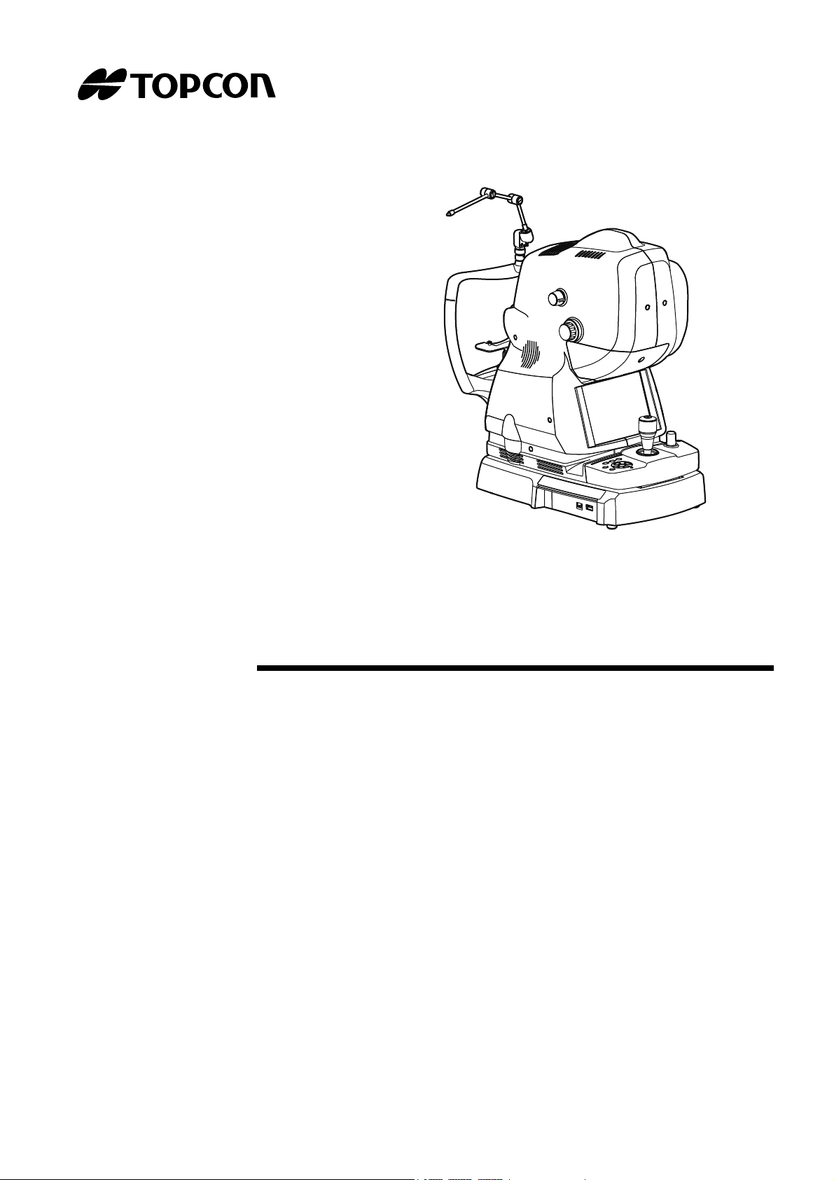
USER MANUAL
3D OPTICAL COHERENCE TOMOGRAPHY
DRI OCT-1
Model Triton
DRI OCT-1
Model Triton (plus)
Page 2

Page 3

INTRODUCTION
0123
CAUTION : Federal law restricts this device to the sale by or on the order of a physician.
Thank you for purchasing the TOPCON DRI OCT-1 Model Triton 3D Optical Coherence Tomography.
INTENDED USE / INDICATIONS FOR USE
The TOPCON DRI OCT-1 Model Triton is a non-contact, high-resolution tomographic and bio-microscopic imaging device. It is indicated for in-vivo viewing, axial cross-sectional and three dimensional
imaging, and measurement of posterior ocular structures, including the retina, retinal nerve fiber
layer, ganglion cell plus inner plexiform layer, ganglion cell complex, macula, optic nerve head, and
choroid. The DRI OCT-1 Model Triton is intended for use as a diagnostic device to aid in the detection and management of ocular diseases including, but not limited to, macular holes, cystoid macular edema, diabetic retinopathy, age-related macular degeneration, and glaucoma.
FEATURES
This instrument is a special photography device to observe, photograph and record the image and
tomogram of fundus and the image of anterior segment and to present its electronic image for diagnosis.
By mounting the anterior segment attachment kit, which is an optional accessory, you can observe,
photograph and record the tomogram of anterior segment.
After photographing, the images and tomograms of fundus and anterior segment can be recorded in
a personal computer where the analysis software is installed.
This instrument is classified into two types depending on the combination of the installed functions:
DRI OCT-1 Model Triton:Not equipped with the FA photography function and with the FAF
photography function.
DRI OCT-1 Model Triton plus*:Equipped with the FA photography function and with the FAF
photography function.
(* "plus" is a catalog symbol.)
PURPOSE OF THIS MANUAL
This manual outlines the DRI OCT-1 Model Triton 3D Optical Coherence Tomography, including
operating procedures, troubleshooting, maintenance and cleaning.
Before using the instrument, carefully read the "DISPLAYS AND SYMBOLS FOR SAFE USE" and
the "GENERAL SAFETY INFORMATION" to familiarize yourself with the features of the TOPCON
DRI OCT-1 Model Triton 3D Optical Coherence Tomography and to ensure that you operate it
safely.
Always keep this User Manual at hand.
1
Page 4

Trademarks
• Microsoft®, Windows®, Windows® 8.1, SQL Server® and Internet Explorer® are either registered
trademarks or trademarks of Microsoft Corporation in the United States and/or other countries.
• Core™ i7 is trademark of Intel Corporation.
• IBM® is a registered trademark of International Business Machines Corporation.
* In general, other company names and product names in this manual are trademarks or the regis-
tered trademarks of those companies.
IPA Font License
IPA font is used in some parts for DRI OCT-1 Model Triton. Any and all terms and conditions of "IPA
Font License Agreement v1.0" shall be deemed to be accepted and agreed by you if you use DRI
OCT-1 Model Triton.
For IPA Font License v1.0, refer to the following URL.
http://ipafont.ipa.go.jp/ipa_font_license_v1.html
2
1. No part of this manual may be copied or reprinted, in whole or in part, without prior written
permission.
2. The contents of this manual are subject to change without prior notice and without legal
obligation.
3. The contents of this manual are correct to the best of our knowledge. Please inform us of
any ambiguous or erroneous descriptions, missing information, etc.
4. Original Instructions
This manual was originally written in English.
©2015 TOPCON CORPORATION
ALL RIGHTS RESERVED
Page 5

CONTENTS
INTRODUCTION ......................................................................................................................... 1
DISPLAYS AND SYMBOLS FOR SAFE USE .................................................................... 5
GENERAL SAFETY INFORMATION .................................................................................... 6
HOW TO USE THIS MANUAL ................................................................................................ 8
GENERAL MAINTENANCE INFORMATION ...................................................................... 8
DISCLAIMERS ............................................................................................................................ 8
POSITIONS OF WARNING AND CAUTION INDICATIONS .......................................... 9
STANDARD ACCESSORIES ................................................................................................ 10
COMPONENTS .................................................................................................................................. 11
COMPONENT NAMES .................................................................................................................. 11
COMPOSITION OF PARTS WHICH CONTACT THE HUMAN BODY .......................................... 11
CONTROL PANEL COMPONENTS .............................................................................................. 12
OPERATION METHOD OF TOUCH DISPLAY .............................................................................. 13
NAMES ON THE TOUCH DISPLAY .............................................................................................. 14
PREPARATIONS ............................................................................................................................... 29
INSTALLING THE INSTRUMENT .................................................................................................. 29
CONNECTING THE POWER CORD ............................................................................................. 30
CONNECTING THE EXTERNAL DEVICE ..................................................................................... 31
RESET FROM POWER SAVE STATE .......................................................................................... 32
BASIC OPERATIONS ....................................................................................................................... 33
FLOW OF OPERATION ................................................................................................................. 33
PREPARATION FOR PHOTOGRAPHY ........................................................................................ 34
FUNDUS TOMOGRAPHY ............................................................................................................. 35
DELETING DATA ........................................................................................................................... 48
SAVING DATA ............................................................................................................................... 48
PRINTING DATA ............................................................................................................................ 48
HOW TO FINISH ............................................................................................................................ 49
OBJECTIVE OPERATIONS ............................................................................................................ 50
COLOR FUNDUS PHOTOGRAPHY .............................................................................................. 50
FUNDUS PERIPHERAL PHOTOGRAPHY .................................................................................... 54
STEREOSCOPIC PHOTOGRAPHY .............................................................................................. 56
FA PHOTOGRAPHY (DRI OCT-1 Model Triton plus) .................................................................... 60
FAF PHOTOGRAPHY (DRI OCT-1 Model Triton plus) .................................................................. 63
ANTERIOR SEGMENT TOMOGRAPHY ....................................................................................... 65
DETAILS OF THE SETTING MENU ............................................................................................. 73
MAINTENANCE ................................................................................................................................. 89
DAILY CHECKUPS ........................................................................................................................ 89
ORDERING CONSUMABLES ....................................................................................................... 89
REPLACING THE XENON LAMP ................................................................................................. 90
REFILLING THE Chinrest tissue .................................................................................................... 91
MAINTENANCE BY THE DEALER ................................................................................................ 91
CLEANING ........................................................................................................................................... 92
CLEANING THE EXTERNAL COVER, TOUCH DISPLAY AND OTHERS ................................... 92
CLEANING OF THE PARTS WHICH COME INTO CONTACT WITH THE PATIENT .................. 92
CLEANING THE TOUCH DISPLAY ............................................................................................... 92
3
Page 6

CLEANING THE OBJECTIVE LENS ............................................................................................. 93
BEFORE REQUESTING SERVICE .............................................................................................. 94
TROUBLESHOOTING ................................................................................................................... 94
SPECIFICATIONS AND PERFORMANCE ............................................................................... 101
SYSTEM DIAGRAM ..................................................................................................................... 101
SPECIFICATIONS ....................................................................................................................... 102
OTHER SPECIFICATIONS .......................................................................................................... 103
SPECIFICATIONS OF THE PERSONAL COMPUTER (COMMERCIAL
PRODUCT) TO BE CONNECTED ............................................................................................... 104
SAFETY OF LED PRODUCT ....................................................................................................... 105
GENERAL INFORMATION ON USAGE AND MAINTENANCE ......................................... 108
INTENDED PATIENT POPULATION ........................................................................................... 108
INTENDED USER PROFILE ........................................................................................................ 108
ENVIRONMENTAL CONDITIONS FOR USE .............................................................................. 108
STORAGE, USAGE PERIOD ...................................................................................................... 108
ENVIRONMENTAL CONDITIONS FOR PACKAGING IN STORAGE ......................................... 108
ENVIRONMENTAL CONDITIONS FOR PACKAGING IN TRANSPORTATION ......................... 108
ELECTRIC RATING ..................................................................................................................... 109
DIMENSIONS AND WEIGHT ....................................................................................................... 109
SYSTEM CLASSIFICATION ........................................................................................................ 109
OPERATION PRINCIPLE ............................................................................................................ 110
CHECKPOINTS FOR MAINTENANCE ........................................................................................ 110
DISPOSAL ................................................................................................................................... 111
PATIENT’S ENVIRONMENT ....................................................................................................... 112
Requirements for the EXTERNAL DEVICE ................................................................................. 113
ELECTROMAGNETIC COMPATIBILITY ..................................................................................... 114
RELATION BETWEEN THE SETTING OF THE ILLUMINATION/FLASH LEVEL AND
MAXIMUM RADIANCE
................................................................................................................... 118
OPTIONAL ACCESSORIES ......................................................................................................... 120
ANTERIOR SEGMENT ATTACHMENT KIT AA-1 ...................................................................... 120
REFERENCE MATERIAL .............................................................................................................. 121
TYPE OF PLUG ........................................................................................................................... 123
DRI OCT-1 Model Triton SOFTWARE LICENSE TERMS .................................................... 124
4
Page 7
DISPLAYS AND SYMBOLS FOR SAFE USE
To encourage safe and proper use and to prevent injury to the operator and others or potential damage to
property, important messages are put on the instrument body and inserted in the manual.
We suggest that everyone understand the meaning of the following displays, icons and text before reading the "GENERAL SAFETY INFORMATION" and observe all listed instructions.
DISPLAY
Display Meaning
Situations in which the device should not be used because the
CONTRAINDICATION
WARNING
CAUTION
NOTE
risk of use clearly outweighs any possible benefit.
Indicates a potentially hazardous situation which, if not avoided,
could result in death or serious injury.
Indicates a potentially hazardous situation which, if not avoided,
may result in minor or moderate injury.
Useful functions to know. Paying attention to these will prevent the
noted problems.
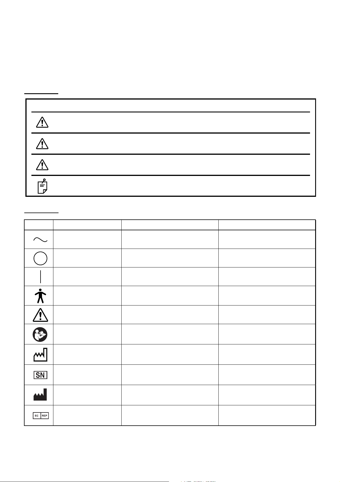
SYMBOL
Symbol IEC/ISO Publication Description Description (French)
IEC 60417-5032 Alternating Current Courant alternatif
IEC 60417-5008
IEC 60417-5007
IEC 60878-02-02 Type B applied part Partie appliquée du Type B
ISO 7010-W001 General warning sign
ISO 7010-M002
ISO 7000-2497 Date of manufacture Date de fabrication
ISO 7000-2498 Serial number Numéro de série
Off (power: disconnection from
the mains)
On (power: connection to the
mains)
Refer to instruction manual/
booklet
Éteint (courant: coupure avec le
secteur)
Allumé (courant: raccordement
sur le secteur)
Symbole d'avertissement
général
Voir le manuel/la brochure
ISO 7000-3082 Manufacturer Fabricant
ISO 15223-1
Authorised Representative in the
European Community
Représentant autorité pour
l’Union européenne
5
Page 8

GENERAL SAFETY INFORMATION
CONTRAINDICATION
When used for red-free photography only, this instrument must not be used for the following patients.
• Patients who are hypersensitive to light
• Patients who recently underwent photodynamic therapy (PDT)
• Patients taking medication that causes photosensitivity.
WARNING
Ensuring the Safety of Patients and Operators
Be careful not to hit the patient's eyes or nose with the instrument during operation.
The patient may be injured.
Handling the cord on this product or cords associated with accessories sold with this product, will expose
you to lead, a chemical known to the State of California to cause birth detects or other reproductive harm.
Wash hands after handling.
Preventing Electric Shocks and Fires
To avoid fire and electric shock, install the instrument in a place free of water and other liquids.
To avoid fire and electric shock, do not put cups or vessels containing liquids near the instrument.
To avoid fire in the event of an instrument malfunction, immediately turn OFF ( ) the Power switch and
unplug the cable if you see smoke coming from the instrument or if you detect other problems.
Don't install the instrument where it is difficult to unplug the cable from the instrument body.
Ask your dealer for repairs.
6
Page 9

CAUTION
Ensuring the Safety of Patients and Operators
Use this instrument carefully on the following patients.
• Patients who have epidemic corneitis, conjunctivitis or any other infectious disease
• Patients who are taking medications that cause light hypersensitivity.
When operating the chin-rest up/down button, be careful not to pinch the patient's hand to avoid possible injury
To avoid injury of the patient, be careful not to bump the patient's eye or nose with the instrument when
operating the touch panel.
Preventing Electric Shock
To avoid electric shock, do not insert metal objects into any vents and/or slots.
To avoid electric shock, do not open the instrument.
Request service from an authorized Topcon distributor.
Do not put any substance over the vent on the top surface of the power supply unit. If the vent is covered, the temperature of the power supply unit may rise abnormally to cause a malfunction. To prevent
the instrument from malfunction, do not drop any liquid into the vent.
Electromagnetic Compatibility (EMC)
This instrument has been tested (with 100V/120V/230V) and found to comply with IEC60601-1-2:
2007.
This instrument radiates radio frequency energy within standard and may affect other devices in the
vicinity.
If you have discovered that turning on/off the instrument affects other devices, we recommend you
change its position, keep a proper distance from other devices, or plug it into a different outlet.
Please consult the dealer from whom you purchased the instrument if you have any additional questions.
7
Page 10

HOW TO USE THIS MANUAL
• Read the instructions on pages 1 to 9 before using the machine.
• Regarding connection to various devices, see "CONNECTING THE EXTERNAL DEVICE"on page
31.
• If you would like an overview of the system, begin by reading "BASIC OPERATIONS" (page 33).
GENERAL MAINTENANCE INFORMATION
USER MAINTENANCE
To ensure the safety and performance of the instrument, all maintenance work, unless specified in this
manual, shall be conducted by trained service engineers.
The following maintenance tasks may be done by the user.
For details, see the relevant part of this manual.
Cleaning the objective lens:
The objective lens may be cleaned by the user. For details, see "CLEANING THE OBJECTIVE LENS"
on page 93.
DISCLAIMERS
• TOPCON shall not take any responsibility for damage due to fire, earthquakes, actions by third
persons and other accidents, or damage due to negligence and misuse by the user and any
use under unusual conditions.
• TOPCON shall not take any responsibility for damage derived from inability to properly use this
instrument, such as loss of business profit and suspension of business.
• TOPCON shall not take any responsibility for damage caused from using this instrument in a
manner other than that described in this Instruction Manual.
• Diagnoses made shall be the responsibility of pertaining doctors and TOPCON shall not take
any responsibility for the results of such diagnoses.
• The customer shall take the responsibility to save data and perform backup in case data
should be lost.
When the customer has obtained data through this software and has saved or backed up the
data in a server or personal computer, TOPCON shall not take any responsibility for the loss of
the data, loss of profit or other damages on the customer.
8
Page 11
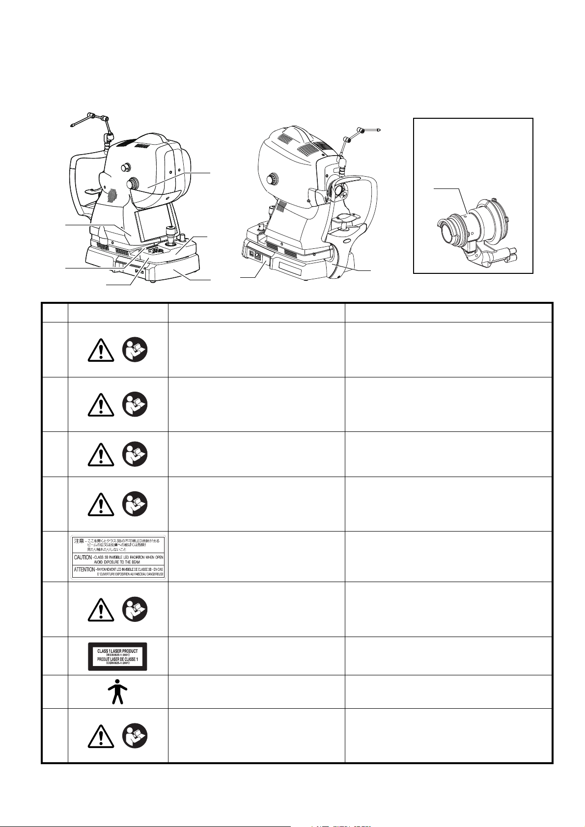
POSITIONS OF WARNING AND CAUTION INDICATIONS
4
3
1
8
2
5
6
Optional accessory:
Attachment kit for
Anterior segment
(Anterior segment
lens unit)
9
7
To ensure safety, this machine provides warning displays. Use the instrument correctly by observing
the display instructions. If any of the following display labels are missing, contact your TOPCON dealer
at the address listed on the back cover.
No. Label Meaning Signification
WARNING
1
To avoid electric shock, do not open
the instrument.
Request service from an authorized
Topcon distributor.
Pour éviter un choc électrique, ne pas ouvrir
l'appareil. Demander le service d'un concessionaire autorisé de Topcon.
WARNING
2
When operating the chinrest up/down
button, be careful not to pinch the
patient's hand to avoid possible injury.
Quand vous fonctionnez le bouton pour
élever/baisser le mentonniére, faire attention
de ne pas pincer la main du patient, ce qui
causerait une blessure.
CAUTION
3
To avoid potential injury during operation, do not touch the patient’s eyes or
nose with the instrument.
Pour éviter une blessure pendant le fonctionnement, ne pas faire toucher l'appareil aux
yeux ou au nez du patient.
CAUTION
4
5
To avoid injury of the patient, be careful not to bump the patient's eye or
nose with the instrument when operating the touch panel.
CAUTIONCLASS 3B INVISIBLE LED RADIATION WHEN OPEN AVOID EXPOSURE TO THE BEAM.
Pour éviter une blessure du patient, faire
attention de ne pas heurter les yeux ou le nez
du patient contre l'appareil pendant le fonctionnement du touche-panneau.
ATTENTION RAYONNEMENT LED INVISIBLE DE
CLASSE 3B - EN CAS D’OUVERTURE
EXPOSITION AU FAISCEAU DANGEREUSE
CAUTION
6
7
8
9
To avoid injury, be careful not to pinch
your fingers when operating the main
unit up and down.
CLASS 1 LASER PRODUCT
(IEC60825-1:2001)
Degree of protection against electric
shock
: TYPE B APPLIED PART
To avoid injury of the patient, be careful not to bump the patient's eye or
nose with the lens unit when operating
the instrument.
CAUTION
Pour éviter une blessure, faire attention de ne
pas se pincer les doigts pendant le fonctionnement vers le haut et vers le bas de l’unité
principale.
PRODUIT LASER DE CLASSE 1
(CEI60825-1:2001)
Degré de protection contre les chocs électriques
: TYPE B PARTIE D'APPLICATION
Pour éviter une blessure, faire attention que
l’unité de lentille ne heurte pas les yeux ou le
nez du sujet pendant le fonctionnement de
l’unité principale.
MISE EN GARDE
MISE EN GARDE
PRÉCAUTION
PRÉCAUTION
PRÉCAUTION
PRÉCAUTION
9
Page 12
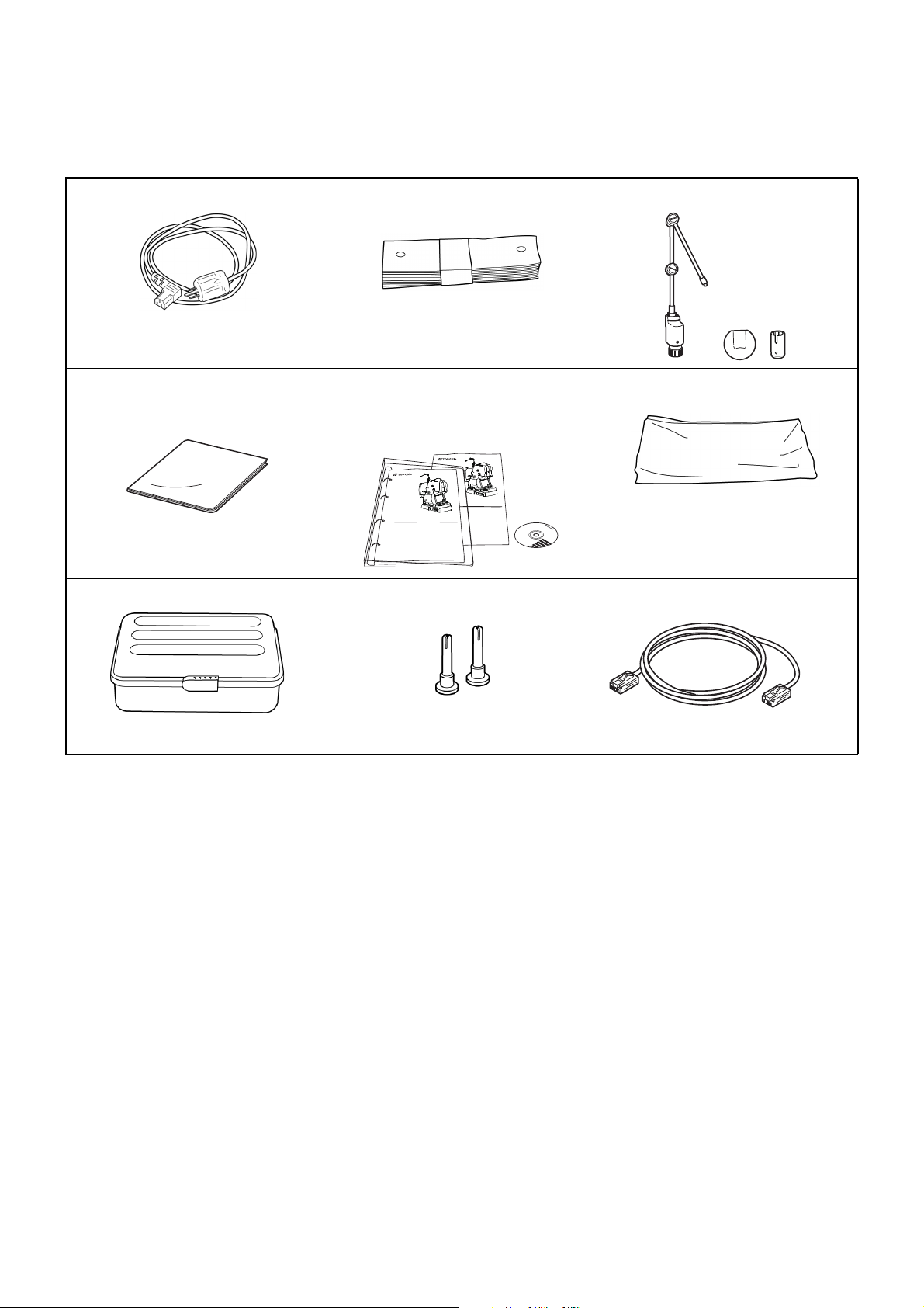
STANDARD ACCESSORIES
Upon unpacking, make sure that all the following standard accessories are included.
Figures in ( ) are the quantities.
Power cord (1) Chinrest tissue (1) External fixation target (1)
Monitor cleaner (1) User manual, Unpacking and
Dust cover (1)
assembly manual and Analysis
software DVD (1 each)
UNPACKING AND ASSEMBLY MANUAL
3D OPTICAL COHERENCE TOMOGRAPHY
USER MANUAL
3D OPTICAL COHERENCE TOMOGRAPHY
DRI OCT-1
Model Triton
DRI OCT-1
Model Triton (plus)
DRI OCT-1
Model Triton
Accessory case (1) Chinrest tissue pins (2) LAN cable (1)
10
Page 13
COMPONENTS
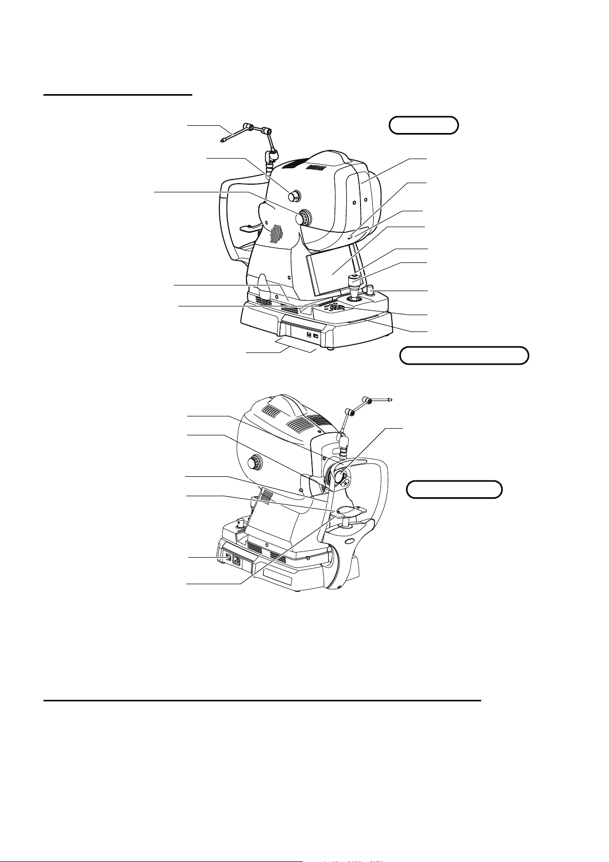
Main unit
Power supply unit
Chinrest unit
External fixation target
Diopter compensation lens
selector
Focusing knob
Base clamping knob
Touch display
External connection terminal
External cover
Photography button
Control lever
Vertical position mark
Sliding board
Power lamp
Forehead rest *1
Eye height mark
Forehead rest base
Chinrest tissue pin
Chinrest *1
Objective lens (Laser aperture)
Lamp house cover screw
Lamp house cover
*1: Contacting part (class B)
Power switch
Control panel
COMPONENT NAMES
COMPOSITION OF PARTS WHICH CONTACT THE HUMAN BODY
Forehead rest : Silicone rubber
Chinrest : Acrylonitrile butadiene styrene resin
Chinrest tissue : Paper
Chinrest tissue pin : Polyamide resin
11
COMPONENTS
Page 14
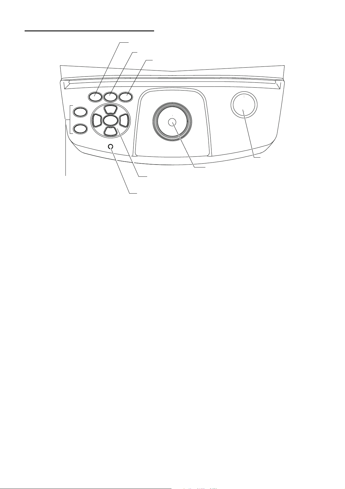
CONTROL PANEL COMPONENTS
Base clamping
knob
Chinrest up/down button
Power lamp
Photography button
Internal fixation target position move button
(Up/Down/Left/Right/Reset)
Small pupil diaphragm selector button
Split button
External fixation target selector button
Chinrest up/down button : Adjusts the chinrest up/down movement.
Internal fixation target
: Adjusts the internal fixation target position finely.
position move button
Power lamp : Displays "power ON" (this lamp is ON), "power OFF" (this lamp is
OFF) and "power save" (this lamp blinks).
Photography button : Starts photography.
Base clamping knob : Locks and unlocks the base.
Small pupil diaphragm
: Sets the small pupil diaphragm to ON/OFF.
selector button
Split button : Sets the split lines to ON/OFF.
External fixation target
selector button
: Sets the external fixation target to ON/OFF.
12
COMPONENTS
Page 15
OPERATION METHOD OF TOUCH DISPLAY
Tap → To select any relevant item.
Touch the screen softly with a finger.
Operate the touch display by your fingers. Don't use any sharp tool such as a
NOTE
ball point pen.
The touch display may be damaged to cause an incorrect operation.
13
COMPONENTS
Page 16

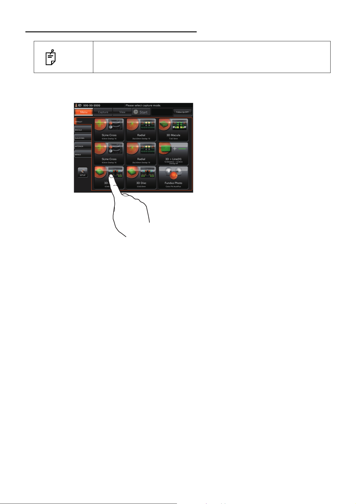
NAMES ON THE TOUCH DISPLAY
Capture icon
display area
Patient ID display area
[SET UP]
button
Message display area
Capture icon tab
[Follow-up]
button
Display areas and functions on the touch display
Information is displayed on the touch display and you can perform a variety of operations by touching the screen.
Capture icon selection screen
You can select the optimal mode for various types of photography.
Patient ID display area : Displays the patient ID.
Capture icon tab : By selecting a tab, the capture icons registered in each tab are dis-
[SET UP] button : Shifts to the setting menu screen.
Message display area : Displays the message.
Capture icon display area : Displays the capture icons.
[Follow-up] button : • Each time you press this button, "Follow-up ON" (button is orange)
played.
and "Follow-up OFF" (button is black) is changed each other. In
case of "ON", Follow-up photography is done. In case of "OFF", it
is not done.
• Follow-up photography is applied to the following cases.
• When selecting the photography icon to which Follow-up photography is unapplied, Follow-up photography is not done even if this
button is set to "ON".
• When the [Follow-up] button is set to "ON", "Follow up" is displayed
in yellow on the capture icon which is applicable to Follow-up photography.]
• Line ("12mm" is not the object of Follow-up photography.)
• 5 Line Cross
• Radial
14
COMPONENTS
Page 17

Follow-up photography function in DRI OCT-1 Model Triton is as follows: the
処理中です。
しばらくお待ちください。
or
system searches the same scan position as the last photographed data* by
using the live IR image of the present photography to decide the scan position.
NOTE
* "The last photographed data" means the data photographed at the date in the
past. The data captured at the same date as the present photography is not
used for searching in Follow-up photography.
Reading the base line data for Follow-up photography
• Tap the photography icon (to which the Follow-up mode is applied) on condition that the [Follow-up
mode] button is ON (orange). The system reads the last photography data (base line data) that is
relevant to the entered patient ID and the selected photography icon.
• The following message is displayed when the relevant data does not exist.
• One eye data of the relevant data does not exist.
• Both eyes data of the relevant data does not exist.
15
COMPONENTS
Page 18
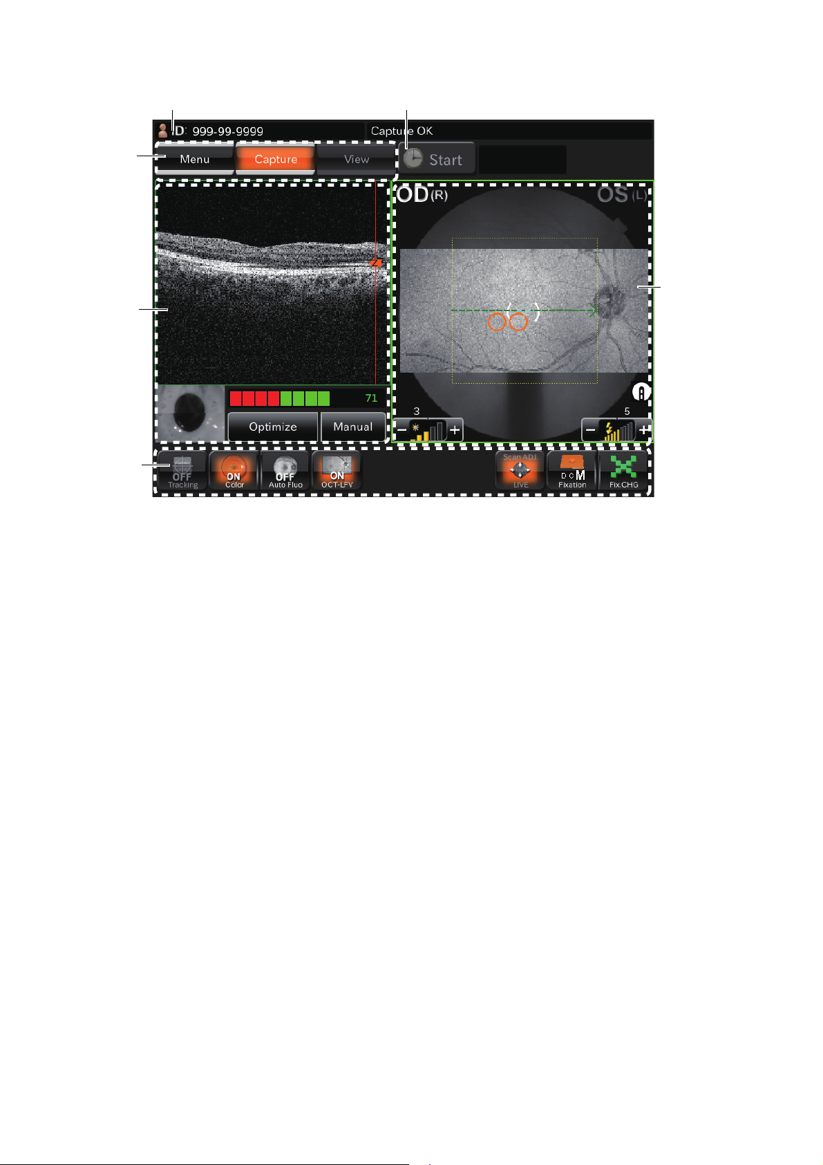
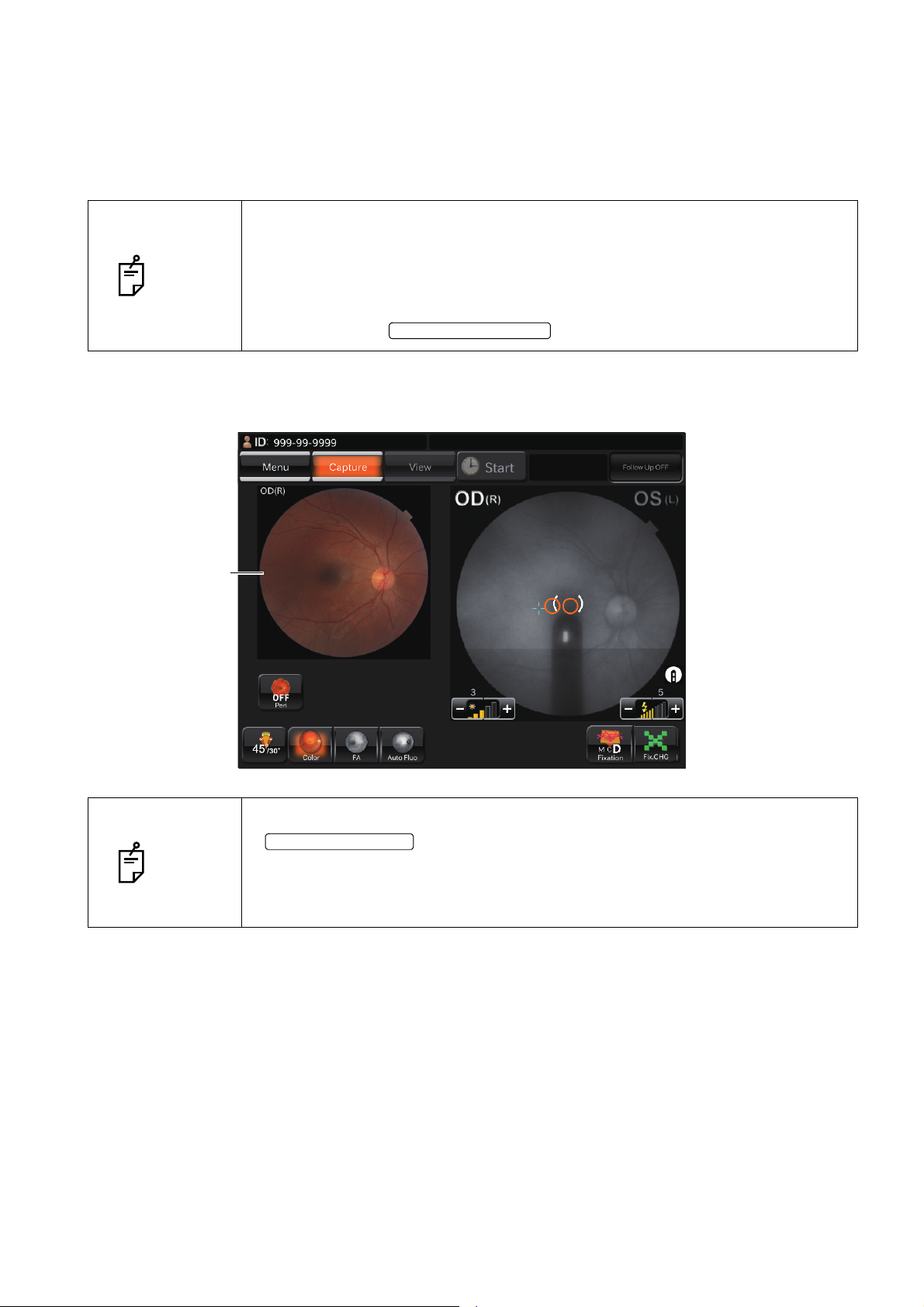
Photography screen (OCT photography)
Tomogram
live image
area
Area 1
Area 2
Patient ID display area Timer button
Fundus/anterior
segment live
image area
Patients ID display area : Displays the patients ID.
Timer button
(Only in DRI OCT-1 Model
Triton plus)
Area 1 : Displays the operation mode buttons and changes the modes.
Area 2 : Changes the internal fixation target and performs other operations.
Tomogram live image area : Displays the tomogram live image. You can perform a variety of oper-
Fundus/anterior segment live
image area
: Used in FA photography. (Refer to page 61.)
ations on the live image. (Refer to page 22.)
: This area displays the live image of fundus or anterior segment and
the graphic image of the scan pattern, which is set on the selected
capture icon, with an interrupted line. The right/left eye, flash level
and illumination level are displayed around the image. You can adjust
the flash level and illumination level with the touch display. (Refer to
page 20.)
In the scan position adjustment mode, the scan position adjustment
range and fine adjustment buttons are displayed. So you can adjust
the scan position with the touch display. (Refer to page 39.)
16
COMPONENTS
Page 19
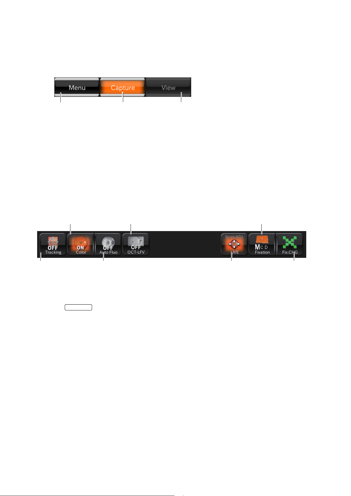
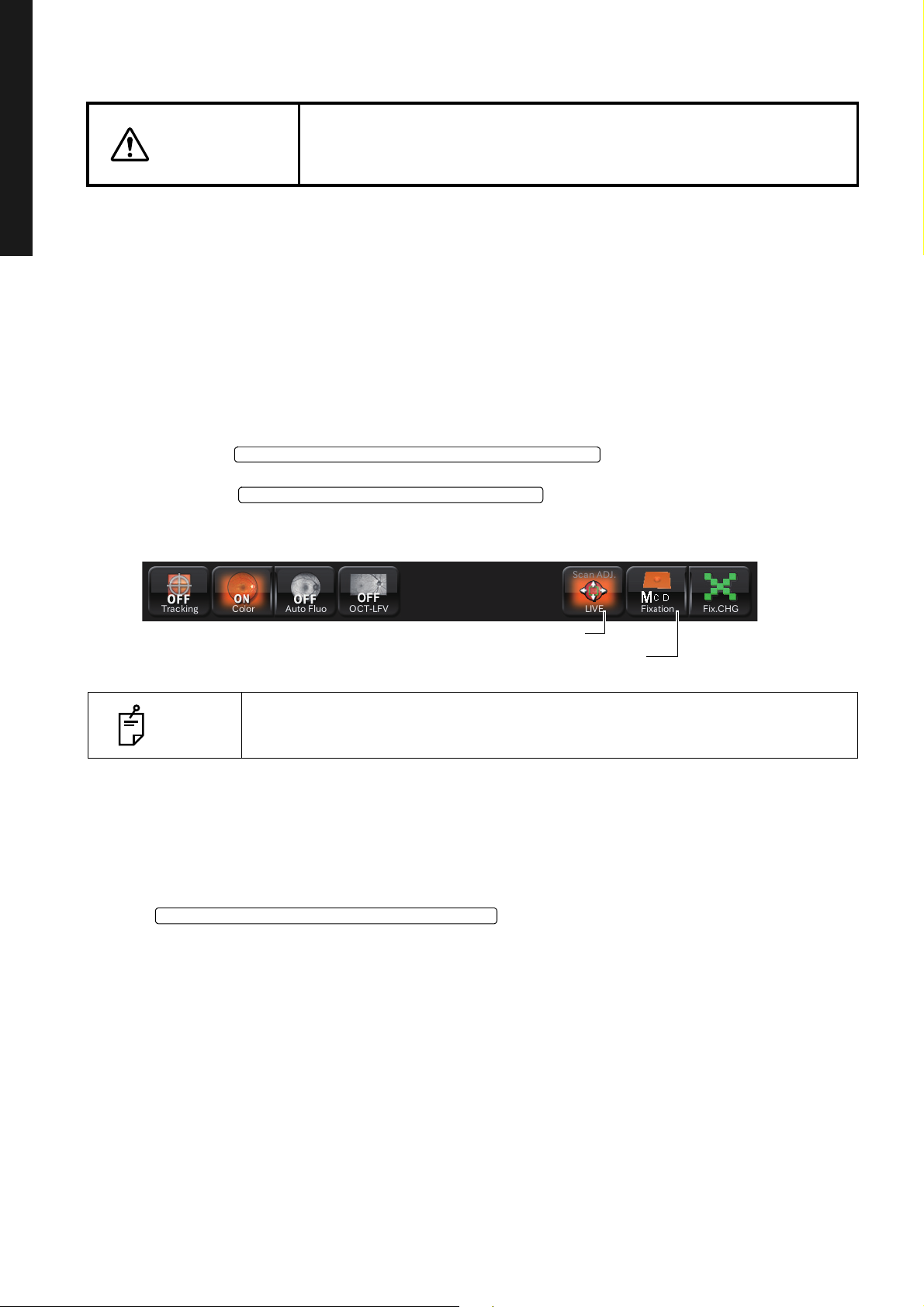
Area 1
Menu button Capture mode button Preview mode button
Internal fixation target
position selector button
Scan position
button
Tracking
button
Internal fixation target
shape selector button
Color fundus
photography button
FAF photography
button
OCT-LFV
image button
TRACKING
Area1 displays the operation mode buttons.You can change to each mode.
The current operation mode is highlighted in orange. The mode that cannot be selected according to
the current status is displayed in gray unclearly. The mode cannot be selected even if you touch the
button in this status.
Menu button : Returns to the photography icon selection screen.
Capture mode button : Shifts to the photography screen to take a picture.
Preview mode button : It is displayed by highlight during a preview.
Area 2
In Area 2, set or change the internal fixation target and adjust the scan position.
Set or change data with the buttons.
• Tracking button
<"Line" scan/"Radial" scan/"5 Line Cross" scan>
Set the button to "ON". The system searches the position specified by the scan position
adjustment mode according to IR image.
In Follow-up photography, the tracking button is always ON and this status cannot be changed. The
system searches the same position as the base line according to IR image.
• Color fundus photography button:
Displays the color fundus photography status (ON/OFF). You can change ON/OFF of color fundus
photography.
• FAF photography button:
(Only in DRI OCT-1 Model Triton plus)
Displays the FAF photography status (ON/OFF). You can change ON/OFF of FAF photography.
• OCT-LFV image button:
You can set whether the OCT-LFV image should be displayed on the live image. When "ON" is
selected for "ON/OFF" after selecting "Setting menu" → "Page 2" → "OCT·FLV" → "ON/OFF", the
tomogram is optimized and then "OFF" is changed to "ON" automatically. So the OCT-LFV image is
displayed.
COMPONENTS
17
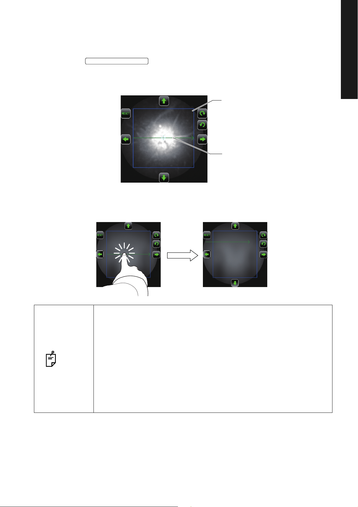
Page 20
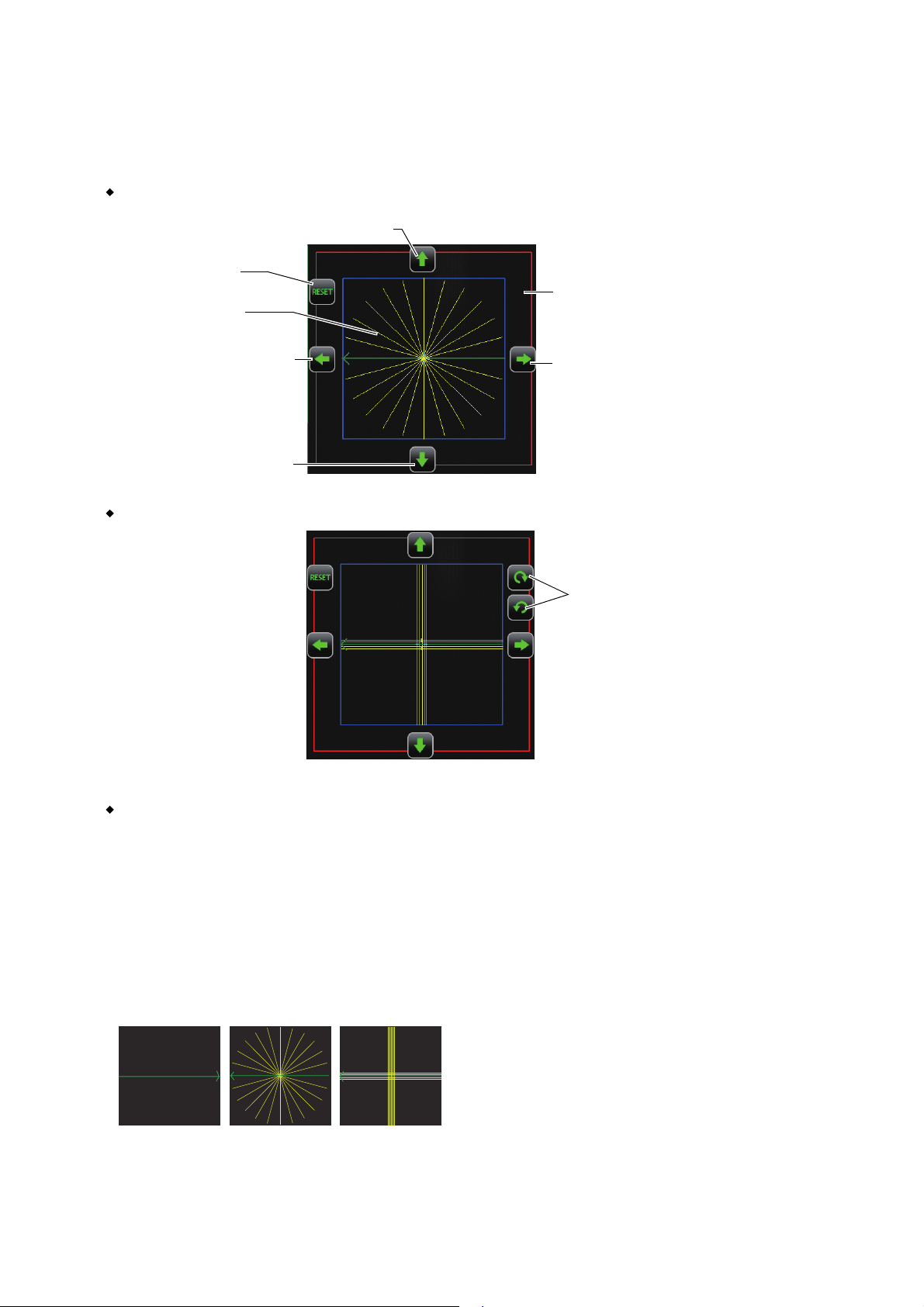
• Scan position button
* Displayed only in Radial/5 Line
Cross scan.
Scan possible range (red)
Fine adjustment button (right)
Fine adjustment button (down)
Fine adjustment button (left)
Scan pattern display
(green and yellow)
Button to reset the
change of position
Fine adjustment button (up)
Rotation button
* Displayed only in Line/5 Line Cross
scan.
Line 5 Line CrossRadial
The scan position adjustment mode is accessed. The selected scan pattern, the scan position
adjustment range, the scan possible range (only in "Radial" and "5 Line Cross" scan) and other fine
adjustment buttons are displayed on the fundus live image area.
Radial scan
5 Line Cross scan
Scan pattern display (green and yellow)
Displays the graphic image of the scan pattern kinds. The green line shows the scan position, and
the arrow shows the scan advance direction. (In case of "Radial" and "5 Line Cross", the arrow
direction for the right eye is reversed for the left eye.)
The yellow line is displayed for the scan pattern except "Line" . For "3D", the yellow line shows the
scan range and, for other scan patterns, the scan position in addition to the position indicated by
the green line. When scan is performed once, it is done at the positions indicated by the green and
yellow lines.
18
COMPONENTS
Page 21

Scan position adjustment range (blue)
Displays the "Scan width × Scan width" range at the focal point on fundus.
In the "Scan width × Scan width" range, it is easy to obtain the sufficient output sensitivity for tomograms.
Scan possible range (red)
Displayed only for "5 Line Cross" and "Radial" scan patterns. This range shows the "12.0mm×
12.0mm" range at the focal point on fundus. This is the limit range where you can get a tomogram
by using this instrument. If a tomogram exceeds the range indicated by the blue line, you cannot
always get the sufficient output sensitivity because the pupil and others obstruct the photography.
Fine adjustment buttons (up/down/right/left)
Each time you touch these buttons, the scan position is moved by about 0.03mm (on fundus) in
the arrow direction.
Rotation buttons (clockwise/counterclockwise)
Displayed only for "Line" and "5 Line Cross" scans. Each time you touch these buttons, the scan
line is rotated by 1° in the arrow direction.
RESET button
Press this button. The changes for the position, which were performed by the fine adjustment buttons and rotation buttons, are reset. The initial position is set again.
• Internal fixation target position selector button
When selecting the fundus capture icon, the internal fixation target position (one of "D", "C" and "M")
is displayed according to the setting. The fixation target position is changed to "D", "C" and "M" in
turn by touching this button.
In "Wide" scan, "Wide" is fixed.
D (Disc):
Optic disc is the center of the screen.
C (Center):
The middle position between macula and optic disc is the center of the screen.
M (Macula):
Macula is the center of the screen.
• Internal fixation target shape selector button
Displays the selected internal fixation target shape. You can select the internal fixation target shape
among the following five shapes by pressing this button.
• 1 dot/4-dot rectangle/4-dot rhomb/×/cross
19
COMPONENTS
Page 22
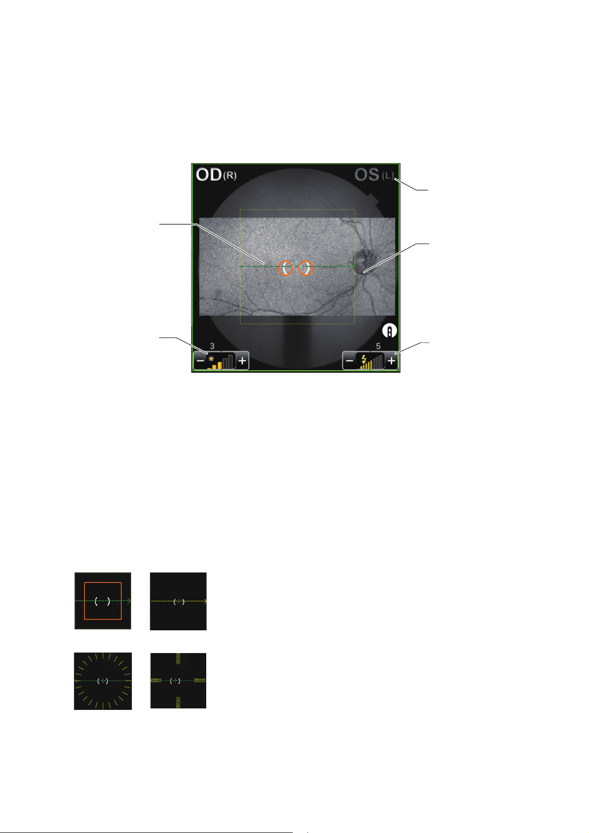
Fundus/anterior segment live image area
Right/left eye
display
Live image
Flash level
display
Scan pattern display
(green and yellow)
* Dotted line
Illumination
level display
3D (H) Line
5 Line CrossRadial
This area displays the fundus live image, the right/left eye, illumination level and besides, the graphic
image of the scan pattern, which is set on the selected capture icon, with an interrupted line. You can
set ON/OFF of the illumination level by the touch display. In the scan position adjustment mode, the
interrupted line of the scan pattern display is changed to the solid line display. The scan position
adjustment range and fine adjustment buttons are displayed. You can adjust the scan position by the
touch display.
• Live image:
Displays the fundus live image.
• Scan pattern display (green and yellow):
Displays the graphic image of the scan pattern, which is set on the selected capture icon. The
green line shows the scan position, and the arrow shows the scan advance direction. (The arrow
direction for the right eye is reversed for the left eye.)
The yellow line is displayed for the scan pattern except "Line". For "3D", the yellow line shows the
scan range and, for other scan patterns, the scan position in addition to the position indicated by the
green line. When scan is performed once, it is done at the positions indicated by the green and yellow lines.
The length and size of the lines are changed according to the set value of scan size.
• Right/left eye display:
20
COMPONENTS
Page 23

In the case of left eye, "OS(L)" is displayed at the upper right position of the live image. In the case
of right eye, "OD(R)" is displayed at the upper left position.
• Illumination level display:
Displays the illumination level (level) by five steps (value: 1 to 5). You can adjust the illumination
level by touching the screen. (Refer to P.40.)
• Flash level display:
Displays the flash level (level) by nine steps (value: 1 to 9). You can adjust the flash level by touching the screen. (Refer to P. 40.)
• Tracking photography
The display color of the scan pattern on the IR fundus image shows whether tracking is successful
or not in "Radial", "Line" and "5 Line Cross" scan.
• When tracking is OFF, the green dotted line is displayed.
• When the scan position is not specified on condition that tracking is ON or when the base is
pulled forward, the yellow dotted line is displayed.
• After tracking is ON and the scan position is specified or when tracking is OK in Follow-up photography, the light blue solid line is displayed.
• After tracking is ON and the scan position is specified or when tracking is NG in Follow-up photography, the red solid line blinks.
21
COMPONENTS
Page 24
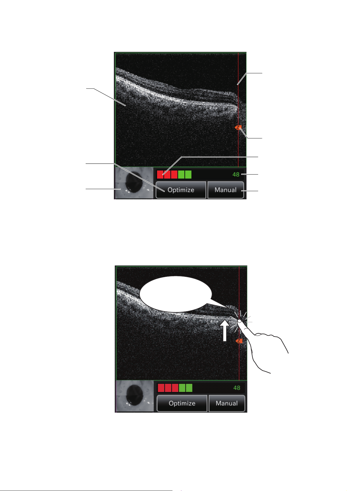
Tomogram live image area
Stereoscopic image
[Image Quality]
level meter
Image Quality value
(IQV)
Z lock position
display bar
Z lock position
[Optimize] button
[Manual] button
Live image
Z lock position is moved.
This area displays the tomogram live image. Perform the operation on the live image.
• Z lock position : Displays the center position of the displayed tomogram.
• Z lock position display bar : Indicates the Z lock position changeable range. By touching an
optional position on the bar, you can move the center position of the
displayed tomogram to the touched position.
22
COMPONENTS
Page 25
• Image Quality value (IQV) : Displays the "Image Quality" level with a value.
Optimize
Manual
Manual
Manual
• Image Quality value (IQV) is the image quality evaluation standard peculiar to
TOPCON. IQV shows the image quality of the tomograms obtained by the DRI
OCT-1 Model Triton with a value quantitatively. When you need a tomogram
applicable to image analysis or other processing, the IQV must be 40 or
NOTE
higher. If the IQV is 40 or higher, the tomogram has a proper image quality. If
the IQV is less than 40, image analysis can be performed for the tomogram
but the reliability on the analysis result is reduced. So the tomogram is not
applicable for analysis.
• If only the images of poor image quality are obtained, contact your dealer or
TOPCON listed on the back cover.
• [Image Quality] level
meter
• Live image : Displays the live tomogram image.
• Stereoscopic image : Displays the image of the anterior segment stereoscopic camera.
• [Optimize] button : After detecting the retina position automatically, this button optimizes
• [Manual] button : If the tomogram is not found automatically by the button, tap
When pressing the button, the Z lock position indicates the position
NOTE
against the reference mirror operating range. The Z lock position when pressing the button does not have the function to move the displayed tomo-
gram center position.
: Displays the "Image Quality" level with meter.
the image output sensitivity to display a clear tomogram. Moreover,
this button performs the OCT auto focus operation according to the
setting (default).
the button and operate the Z lock position. You can search
the retina position.
23
COMPONENTS
Page 26
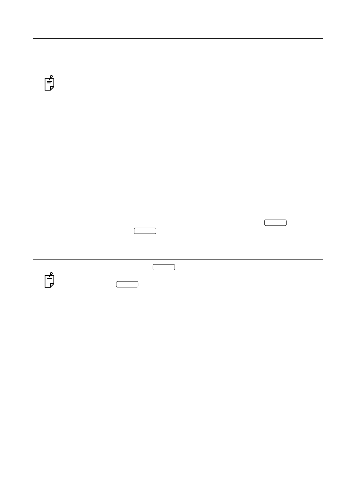
Preview screen (OCT photography)
Tomogram
preview area
Fundus
photographed
image
Scanned
range
Delete button
Scan position (icon)
After OCT photography, the preview screen shown below appears.
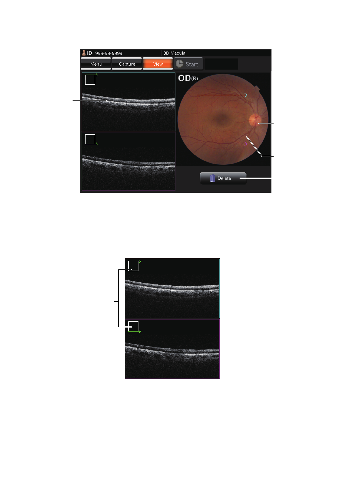
Tomogram preview area : Previews the photographed tomograms.
When there are two or more images in "3D" or "Radial" scan, the typical image is displayed in this area. In "3D" scan, the two images at
both ends are regarded as the typical images and, in "Radial" scan,
the two images (vertical and horizontal) are regarded so.
For each image, an icon that indicates the scan position is displayed.
Fundus photographed image : Displays the fundus image taken by each photographing action.
Delete button : Deletes the photography result.
24
COMPONENTS
Page 27
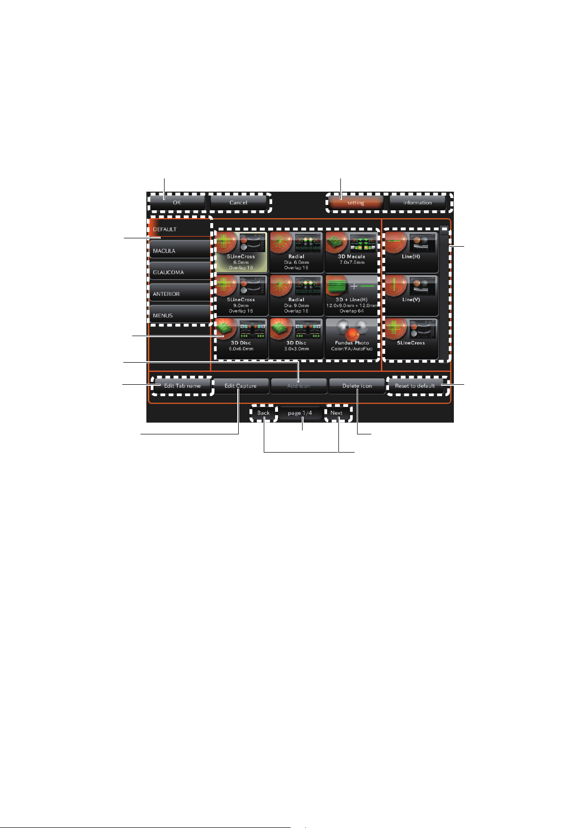
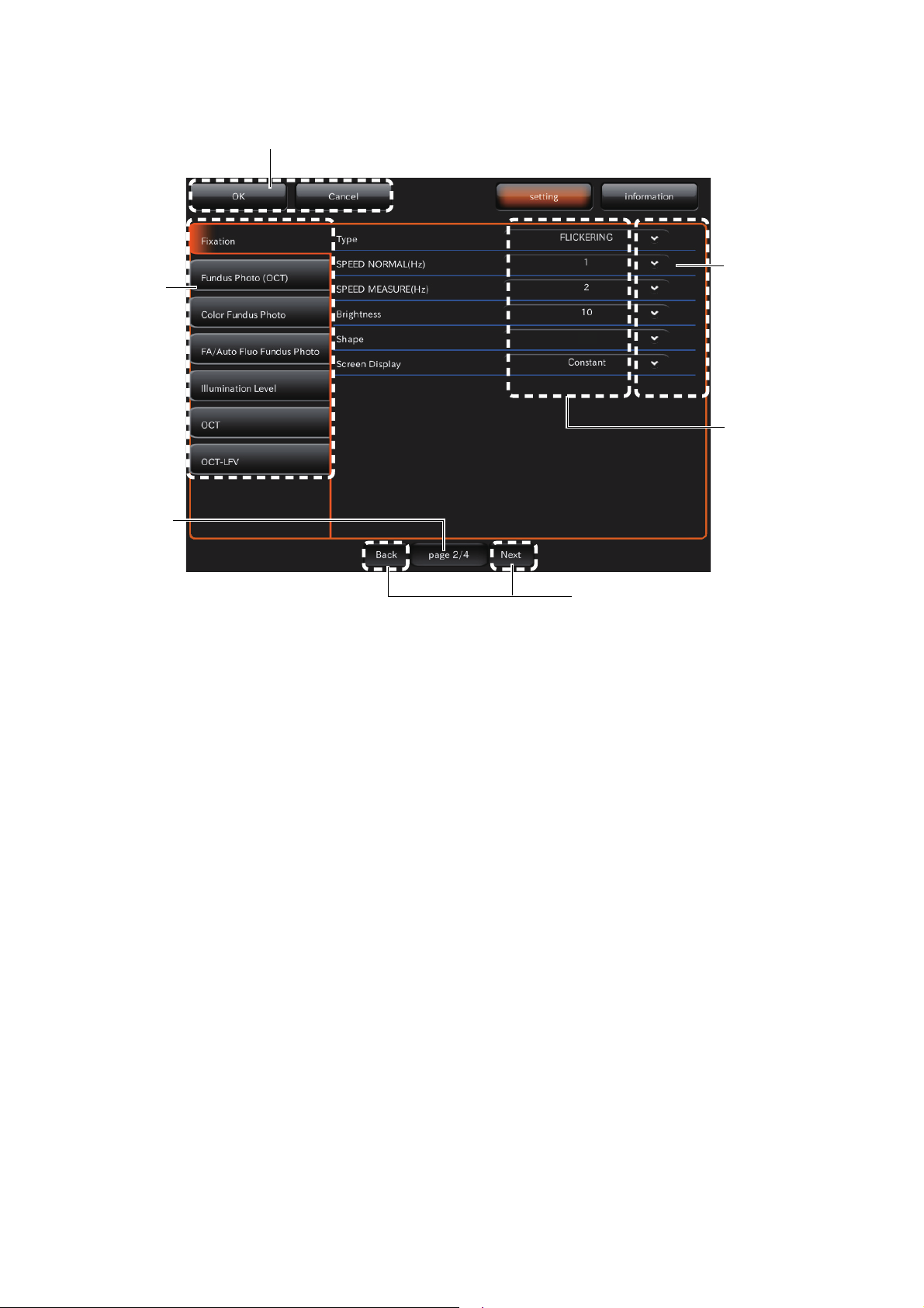
Setting menu screen
Page forward/backward button
Capture icon tab
Icon layout setting
area
Function button
Page number
Capture icon list
Menu selector button
[Add icon] button
[Delete icon] button
[Edit Tab name]
button
[Edit Capture] button
[Reset to default]
button
You can set many kinds of data for this instrument on this screen.
On the capture icon selection screen, which is the initial screen, press the [SET UP] button. This
screen appears.
• Capture select screen
Set the icon display on the capture icon select screen and the parameters for each capture icon.
Function button : Saves and cancels the setting.
Menu selector button : You can change the setting screens for the photography mode and for
Capture icon list : Displays all the capture icons. You can view the hidden capture icons
Page number : Displays the current setting menu page's number in page order.
Icon layout setting area : Sets the icons that will be displayed on the Capture icon selection
Page forward/backward
button
[Edit Capture] button : Shifts to the parameter setting screen to check and change the param-
Capture icon tab : Select a tab, and the photography icons, which are registered in each
the information to each other.
using the scroll bar at the right.
screen, which is the initial screen.
: Shifts to the other pages in the setting menu.
eters for the capture icon selected in the icon layout setting area.
tab, are displayed.
25
COMPONENTS
Page 28

[Add icon] button : Adds the icon, which is selected on the capture icon list, to the icon
layout setting area. When you select a capture icon in the icon layout
setting area, the icon is added to the left side or upper right corner of
the capture icon.
[Delete icon] button : Deletes the capture icon, which is selected in the icon layout setting
area. After deleting, the remaining capture icons are placed in order
on the left.
[Edit Tab name] button : Changes the name of the capture icon tab.
[Reset to default] button : Returns the changed capture icon to the default.
26
COMPONENTS
Page 29
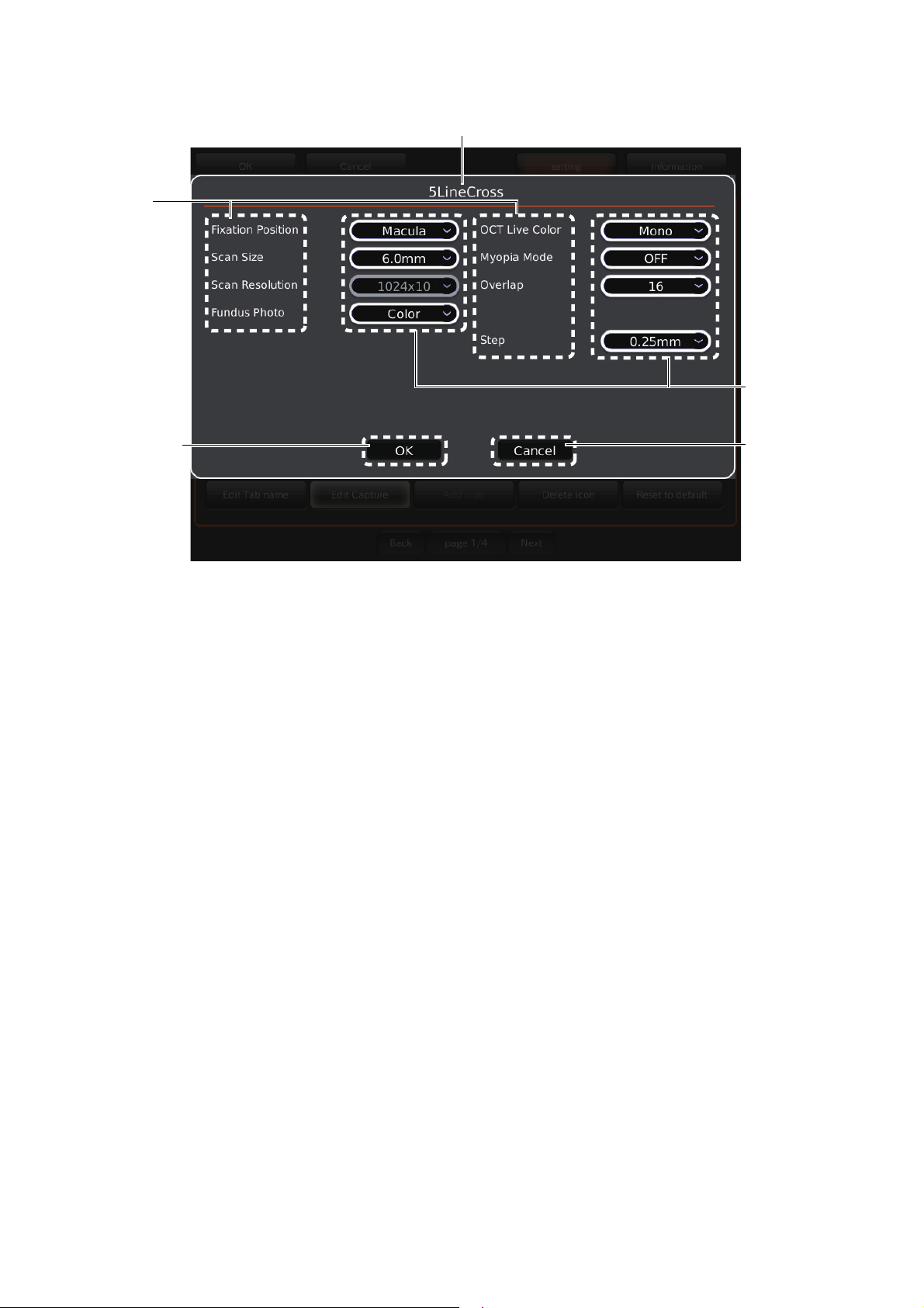
•
Item name
Capture icon name
Item value
selector button
OK button
Cancel button
Parameter setting screen
Set the parameters for the capture icon selected in the icon layout setting area.
Display of the capture icon
: Displays the selected capture icon name.
name
Item name : Displays the objective items of the parameters for the selected cap-
ture icon.
Item value selector button : Displays the set value of each item. Select the desired item.
OK button : Validates the changed contents and returns to the menu screen.
Cancel button : Returns to the menu screen. The changed contents are not validated.
27
COMPONENTS
Page 30
• Photography setting screen • Auto operation setting screen • System setting screen
×
Utility button
Function button
Page number
Item button
Item value display
area
Page forward/backward button
You can set data about photography and system.
Function button : Saves and cancels the setting.
Page number : Displays the current setting menu page's number in page order.
Utility button : Displays the objective items on the current setting menu page.
Page forward/backward
button
Item button : Changes the set status of the selected item.
Item value display area : Displays the current set status of each item.
Select the desired item.
: Shifts to other pages in the setting menu.
28
COMPONENTS
Page 31
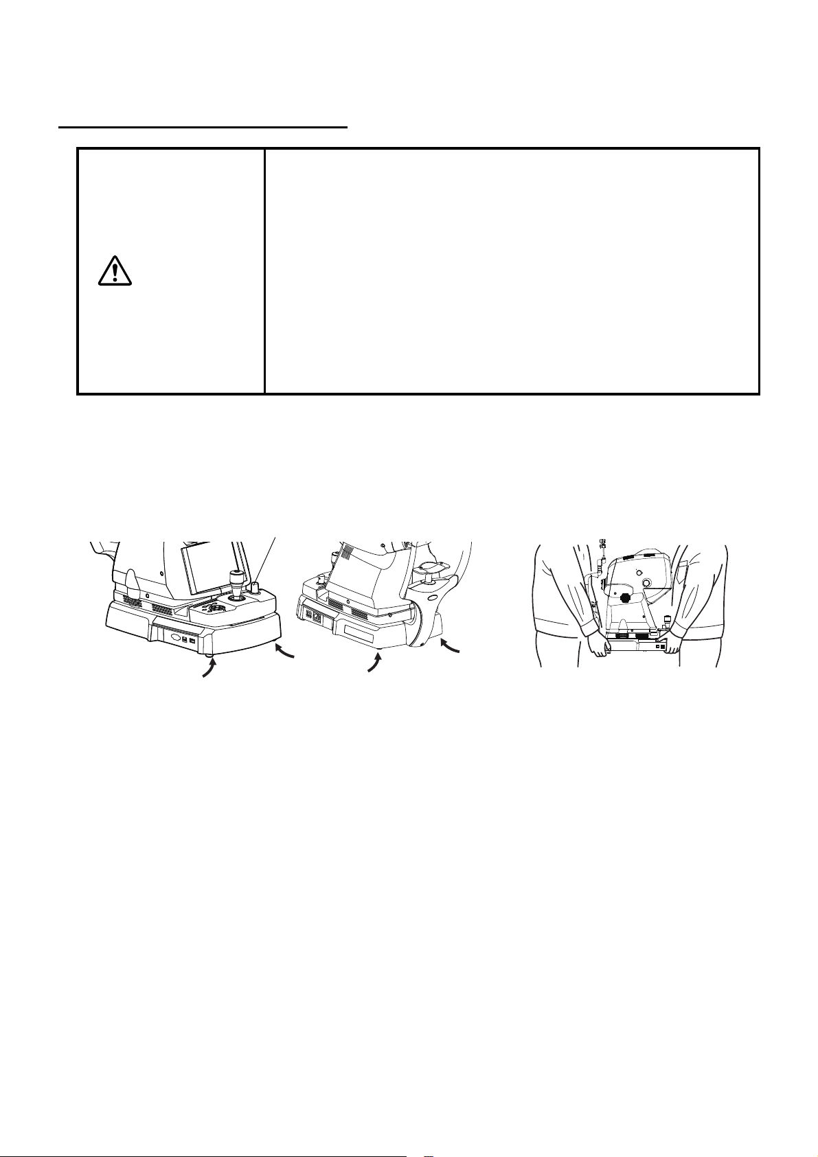
PREPARATIONS
Holding positions
Base clamping knob
Holding the instrument body
INSTALLING THE INSTRUMENT
• To prevent the instrument from falling and to avoid injury during carrying, be sure to secure the instrument with the base clamping knob at
the bottom.
• To avoid injury or damage, two people should be employed for supporting the instrument from the underside. Carrying by one person
may result in personal injury and/or damage to the instrument should
CAUTION
1 Turn the base clamping knob clockwise as pushing it to lock the instrument body. (When unpack-
ing, the instrument body is locked.)
the person slip or fall. If you support any other part except the underside, you may be pinched by the instrument or injured by falling.
• To avoid falling and injury while moving the table with the instrument
on top of it, be sure to use an approved automatic instrument table.
• To prevent the instrument from falling and to avoid injury, install the
instrument on a level surface.
2 Firmly hold the instrument body at the specified positions, and put it on the automatic instrument
table.
3 After installing, turn the base clamping knob counterclockwise to unlock the instrument body.
29
PREPARATIONS
Page 32
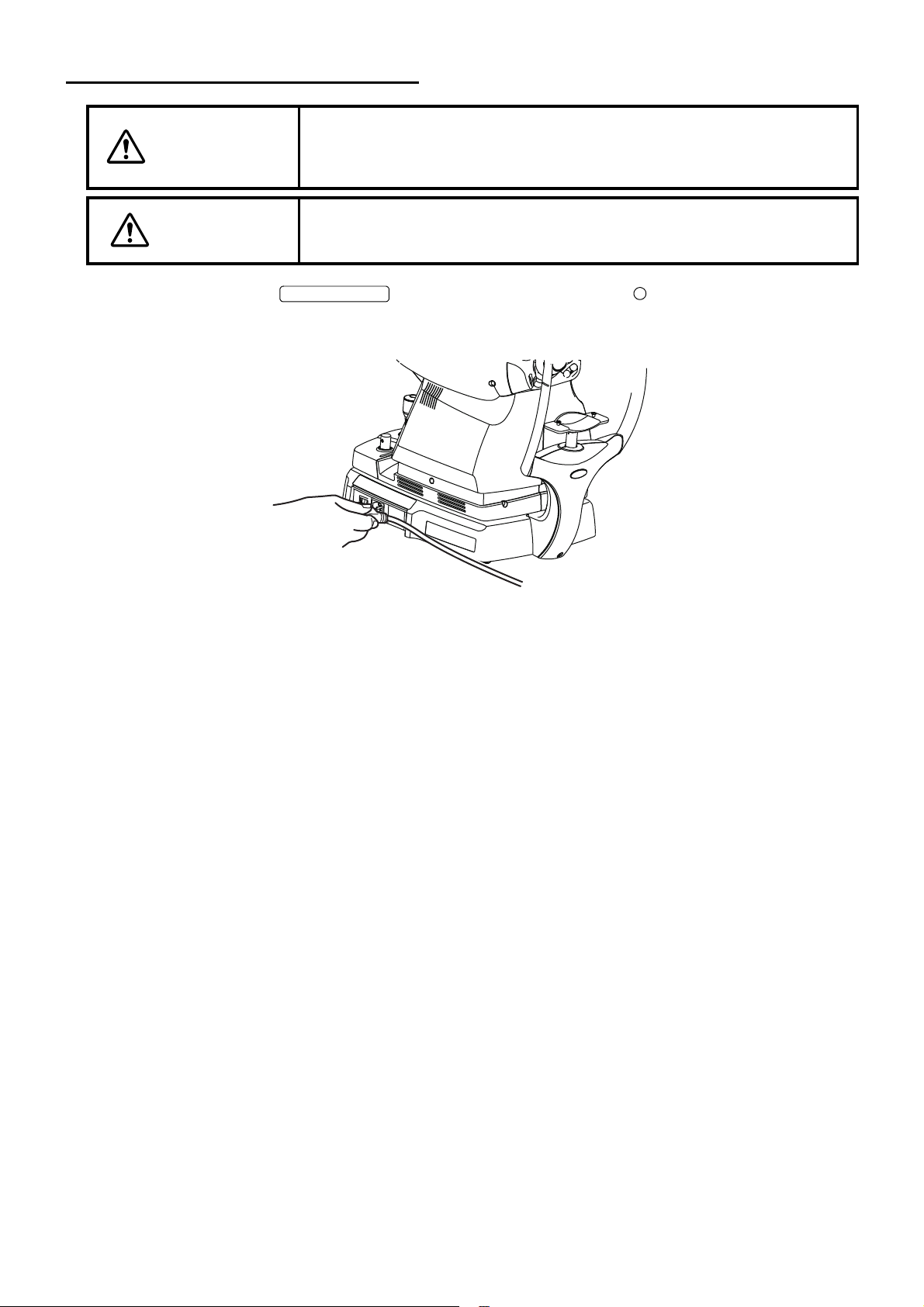
CONNECTING THE POWER CORD
POWER SWITCH
To avoid fire and electric shock in case of leakage, be sure to use a
WARNING
power supply equipped with a 3-pin plug AC receptacle for proper
grounding.
CAUTION
To avoid electric shock, do not handle the plugs with wet fingers.
1 Make sure that the of the instrument body is OFF ( ).
2 Attach the power cord to the instrument body.
3 Plug the power cord into the 3-pin plug AC receptacle.
30
PREPARATIONS
Page 33
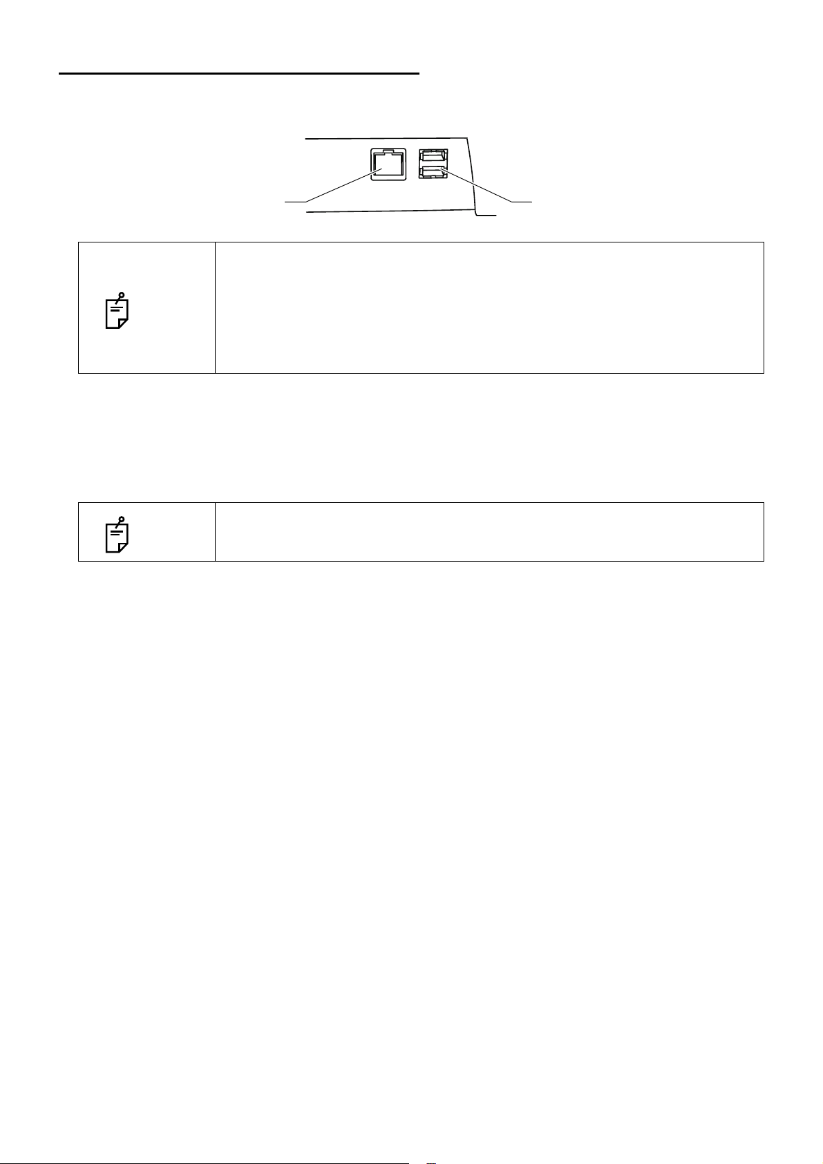
CONNECTING THE EXTERNAL DEVICE
LAN terminal USB terminal
The connection terminals for external devices are arranged on the base unit.
• Use the external device complying with IEC60950-1.
Do not connect any device that is not specified as a system.
NOTE
Connecting to a personal computer
For details about connecting the external devices, contact your dealer or TOPCON (see the back cover).
• USB terminal is provided for maintenance. Others except service engineers
must not use it.
1 Connect the LAN cable, which is the accessory of the instrument, from the personal computer to
the LAN terminal of the instrument.
NOTE
You must install the analysis software,which is the accessory of the instrument,
to the connected personal computer.
31
PREPARATIONS
Page 34

RESET FROM POWER SAVE STATE
PHOTOGRAPHY BUTTON
This machine adopts the power save method for power saving.
When the instrument body (excluding the chin-rest up/down button and focusing knob) is not operated
for a period of time, the power save function stops power supply to the touch display, illumination light
source and photography light source.
1 Tap the control panel or press the .
In a few seconds, the touch display is displayed and ready for photographing.
NOTE
When shipped, the power save set time is 5 minutes.
32
PREPARATIONS
Page 35
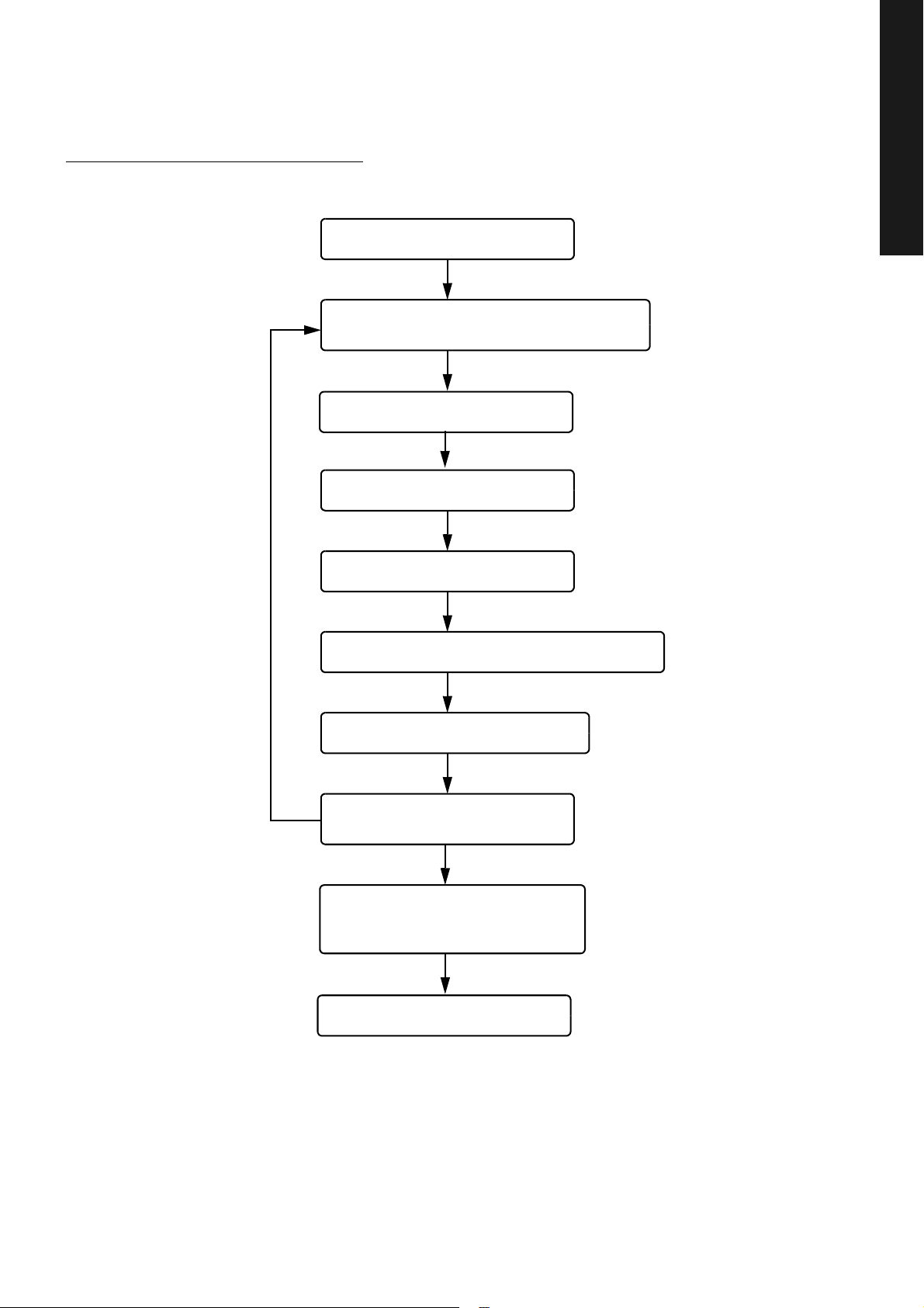
BASIC OPERATIONS
Turning on the power (P.34)
Preparation for personal computer (P.34)
• Inputting the patient information
Setting the patient (P.37)
Setting the illumination level (P.40)
Changing the diopter compensation lens (P.41)
Alignment and photography (P.42)
Transferring the data to the external personal computer
Finish procedure (P.49)
Saving data
Printing data
*by the external personal computer
Setting the capture icon (P.35)
FLOW OF OPERATION
BASIC OPERATIONS
FLOW OF OPERATION
33
BASIC OPERATIONS
Page 36

BASIC OPERATIONS
POWER SWITCH
Capture
PREPARATION FOR PHOTOGRAPHY
Connecting the power supply
1 Check the power cord connection.
For details, see "CONNECTING THE POWER CORD" on page 30.
PREPARATION FOR PHOTOGRAPHY
2 Turn ON ( ) the of the instrument.
3 Confirm that the Title screen is displayed and then in a few seconds the capture icon selection
screen should be displayed.
NOTE
Preparation for personal computer
1 Connect the instrument to the personal computer in which the analysis software, the acces-
sory of the instrument, is installed.
2 Turn on the personal computer.
If the personal computer is not ready, the message "Select patient and start
capture." is displayed. When the preparation for the personal computer has
been completed by the following procedure, the message automatically disappears.
3 Start the analysis software.
4 Enter the patient information.
5 Select .
The preparation of the DRI OCT-1 Model Triton for photography is finished.
NOTE
For details, refer to the instruction manual (for software).
34
BASIC OPERATIONS
Page 37

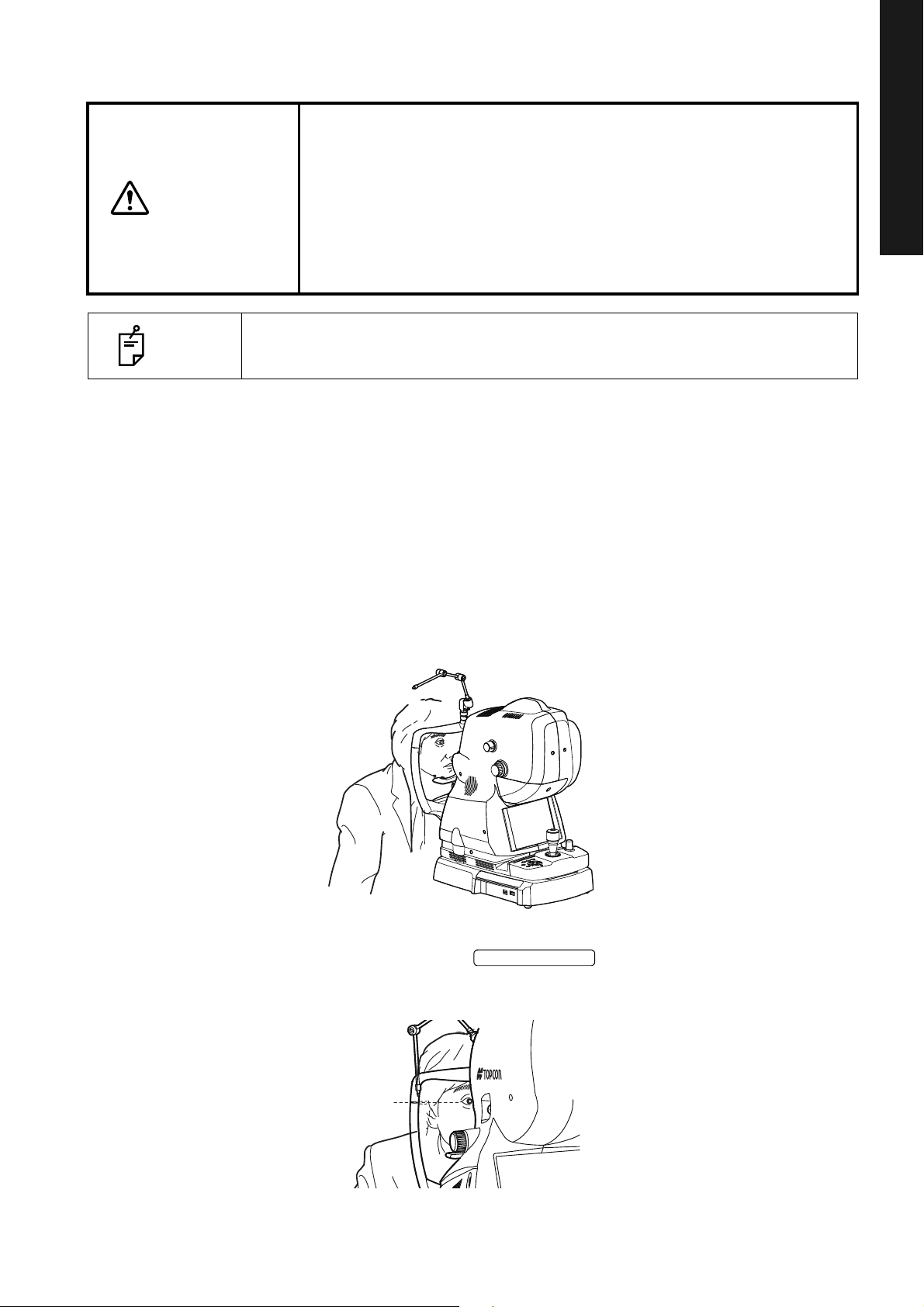
FUNDUS TOMOGRAPHY
To avoid injury of the patient, be careful not to bump the patient's eye or
CAUTION
• Caution in photography
NOTE
• To ensure correct imaging, adjust the table height so the patient can relax with
nose with the instrument and external fixation target when operating the
touch display.
Under the following photography conditions, there is a bright spot on the center of the picture.
• The patient's pupil is small. (This condition includes the case of "When the
small pupil diaphragm is set to ON".)
• The flash level is high.
• Alignment is not adjusted properly.
To improve these conditions, carry out the following operations.
• Darken the room to enhance dilation. When using mydriatic, follow the
judgment of a doctor and the instruction manual about medicine.
• Adjust alignment for the position where the flare is the least visible on the
monitor screen.
• Set the flash level to the lowest setting the environment will allow.
Then, take a picture.
his/her chin placed centrally on the chin-rest.
BASIC OPERATIONS
FUNDUS TOMOGRAPHY
Selecting the capture icon
On the capture icon selection screen, which is the initial screen, touch and select the fundus tomogram
capture icon.
35
BASIC OPERATIONS
Page 38

BASIC OPERATIONS
Capture icon
FUNDUS TOMOGRAPHY
Capture icon
name
Line (H)/
Line (V)
5 Line Cross 6.0mm 1024×10 Macula OFF 16
Radial Dir. 6.0mm 1024×12 Macula OFF 16
3D: Macula 7.0×7.0mm 512×256 Macula OFF
Scan length
9.0mm
Scan
resolution
1024H/
1024V
Fixation
position
Macula OFF 128
Myopia
Mode
Over Scan
Count
3D: Optic disc 6.0×6.0mm 512×256 Disc OFF
3D: Wide (H) 12.0×9.0mm 512×256 Wide OFF
36
BASIC OPERATIONS
Page 39
Setting up the patient
CHINREST UP/DOWN
Canthus marker
CAUTION
• To avoid electric shock, do not touch the external connection terminal,
the cable terminal from the external device and the patient at the same
time.
• When moving the chinrest up and down, be careful not to pinch the
patient's hand to avoid possible injury.
• When moving the main unit, the external fixation target will be pushed
by the measuring head. To avoid injury of the patient, be careful to
prevent the external fixation target from hitting the patient.
BASIC OPERATIONS
NOTE
• If the patient wears glasses or contact lenses, have him/her remove them first.
1 Peel off one chinrest paper. If there is not chinrest paper, supply it. (Refer to P.91.)
2 Wipe off dust on the forehead rest.
3 Seat the patient comfortably on an exam stool or chair in front of the instrument.
4 Adjust the table height or chair height so the patient can relax with his/her chin placed cen-
trally on the chinrest.
Let the patient rest his/her chin on the chinrest.
FUNDUS TOMOGRAPHY
5 Adjust the chinrest height by adjusting the button so the outside corner of the
patient's eye is level with the Canthus marker on the chinrest post.
Let the patient rest his/her forehead on the forehead rest.
37
BASIC OPERATIONS
Page 40
BASIC OPERATIONS
INTERNAL FIXATION TARGET POSITION SELECTOR BUTTON
EXTERNAL FIXATION TARGET SELECTOR BUTTON
Internal fixation target position selector button
Scan position button
INTERNAL FIXATION TARGET POSITION MOVE BUTTON
Setting the picture position
You can change the default picture position, which is set according to the selected capture icon. If nec-
FUNDUS TOMOGRAPHY
essary, you can change the default position to the external fixation target.
There are the following three changing methods. Please change the picture position by your desired
method.
• Changing by using the internal/external fixation target selector button (touch display)
This method is used to change the internal fixation target position and to change the internal fixation
target to the external fixation target.
1 Touch the on Area 2 of photography screen
To avoid injury of the patient, be careful not to bump the patient's eye or
CAUTION
(OCT photography) to change the picture position.
Press the on the control panel, and the target is
changed to the external fixation target. Change to the desired picture position. For the details
of display, refer to P.17.
nose with the instrument when operating the control lever or touch display.
NOTE
• Changing by using the internal fixation target position move button (control panel)
Change the picture position by adjusting the internal fixation target position finely.
When the external fixation target is used, operate the arm to guide the patient's
eye to the correct position.
1 As watching the fundus live image area, press the
up, down, right and left on the control panel to
adjust the internal fixation target position.
38
BASIC OPERATIONS
Page 41
• Changing by using the scan position button (touch display)
SCAN POSITION BUTTON
Scan position adjustment range (blue)
Scan pattern display
Use this method when changing the scan position.
1 Tap the on Area 2 of the photography screen (OCT photography) to
access the scan position adjustment mode. On the fundus live image area, the graphic image
of the selected scan shape and range is displayed with a solid line. For the details of display,
refer to P.18.
2 Touch the scan position adjustment range indicated by a blue frame to move the scan position. For
details, refer to P.
18.
BASIC OPERATIONS
FUNDUS TOMOGRAPHY
NOTE
• To adjust the picture position finely, use the fine adjustment buttons around
the image. To use "rotation", which can be adjusted only for "Line" scan and
"5 Line Cross" scan, perform the rotating adjustment with the rotation buttons
(clockwise/counterclockwise) indicated around the image. For details, refer to
P.18.
• For the scan pattern of "3D", the scan position cannot be adjusted.
• When 3 seconds have passed since the last operation, the scan pattern display status is automatically changed from "solid line" to "interrupted line". In
addition, the scan position adjustment range and fine adjustment buttons disappear on the screen. The instrument exits from the scan position adjustment
mode. You can change "3 seconds" by selecting "Setting menu"
→ "OCT" → "Scan ADJ Duration Time". It is possible to select "1, 2, 3, 5 sec".
→ "Page 2"
39
BASIC OPERATIONS
Page 42

BASIC OPERATIONS
Illumination level
Illumination level Illumination level
display
decreases. increases.
Flash level display
Flash level decreases. Flash level increases.
Setting the illumination level
Tap the "+" of the [Illumination level] display on the fundus/anterior segment live image area,
and the illumination level increases. Tap the "-", and the illumination level decreases.
FUNDUS TOMOGRAPHY
Setting the flash level
CAUTION
To avoid discomfort to the patient, do not brighten the photography light
more than necessary.
Tap the “+” of the [Flash level] display on the fundus/anterior segment live image area, and the
flash level increases. Tap the “-”, and the flash level decreases.
When color fundus photography is set to OFF or when the instrument without the fundus photography
function is used, the flash level is not displayed and cannot be adjusted.
40
BASIC OPERATIONS
Page 43
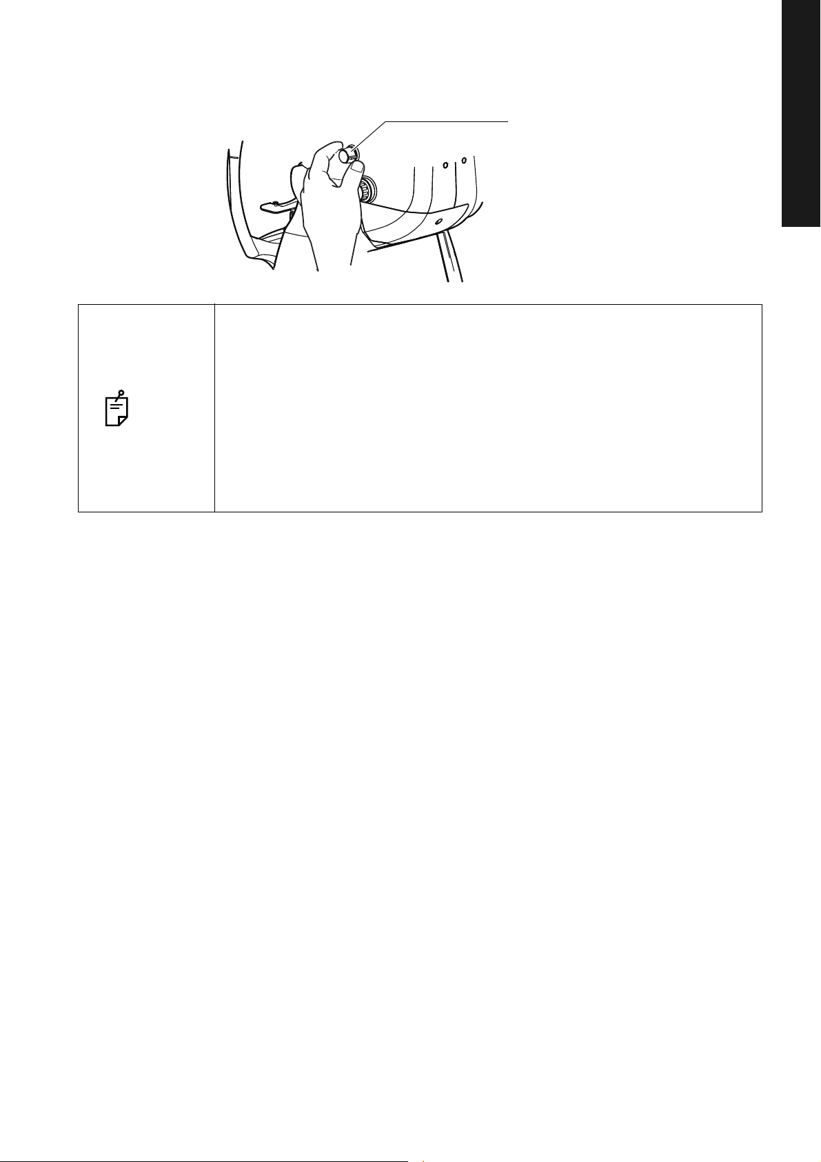
Changing the diopter compensation lens
Diopter compensation
lens selector
Turn the diopter compensation lens selector to compensate the dioptric power for the patient's eye.
• When the patient's eye has a strong myopia, turn the diopter compensation
lens selector and set it to (-).
• When the patient's eye has a strong hyperopia, turn the diopter compensation
lens selector and set it to (+).
NOTE
• When the diopter compensation lens is set to a value other than "0", the split
Compensation range: 0 : -13 – +12D
-
: -12 – -33D
+ : +11 – +40D
lines disappear. At the same time, the function of the auto focus is invalidated.
BASIC OPERATIONS
FUNDUS TOMOGRAPHY
41
BASIC OPERATIONS
Page 44

BASIC OPERATIONS
Operating the control lever
(in back and forth/right
and left directions)
Base clamping knob
Operating the control lever
(in a vertical direction)
Vertical position mark
Alignment and photography
CAUTION
• To avoid injury while moving the instrument body, do not put your hand
into the gap between the main unit and power supply unit.
• To avoid injury to the patient's eyes and nose while moving the instrument body, be attentive to the distance between the patient and the
objective lens.
FUNDUS TOMOGRAPHY
The alignment operation is done with the control lever.
•
Fine movements of the base, back and forth and right and left, are done by tilting the control lever.
Before performing this operation, free the base by turning the Base clamping knob to the left.
To lock the base, turn the Base clamping knob to the right.
• To move the instrument body up/down, turn the control lever right for upward movement, and left for
downward movement.
The vertical position mark indicates the standard for the instrument's vertical position.
42
BASIC OPERATIONS
Page 45

1 Hold the control lever and pull the instrument to the utmost limit toward the operator. As the
OD
(R)
OS
(L)
15
Well dilated. Narrowly dilated for
photography.
Pupil diameter is too small:
darken the room and further
dilate the pupil.
Pupil diameter > φ4.0mm
Pupil diameter = φ4.0mm Pupil diameter < φ4.0mm
internal fixation target turns on, instruct the patient to look at the fixation target in the center.
Observe the anterior segment image on the touch display.
2 Move the instrument body in right and left / up and down directions with the control lever until
you get the patient's eye in the center of the fundus live image area.
BASIC OPERATIONS
FUNDUS TOMOGRAPHY
NOTE
Now hold the control lever upright, which will facilitate the total alignment process.
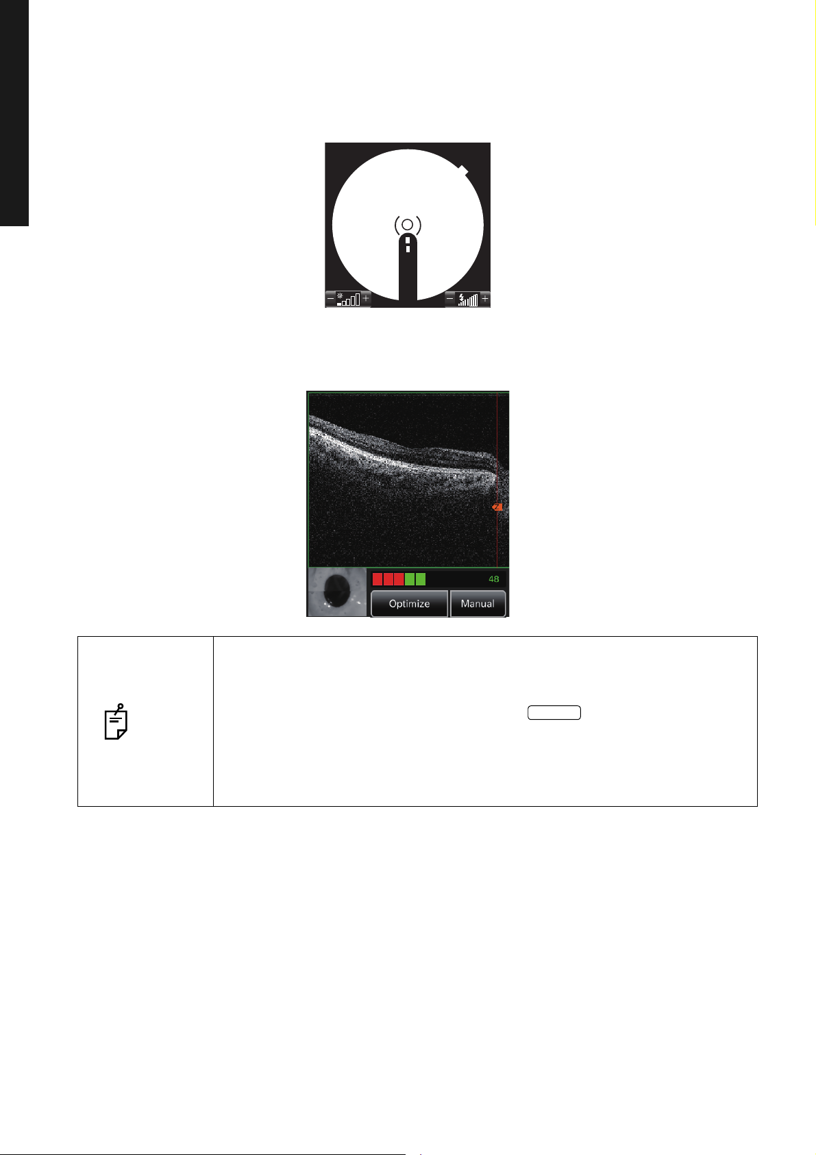
3 On the touch display, bring the ( ) scale towards the patient's pupil, and make sure that the
pupil is larger than the ( ) scale.
Comparison of the ( ) scale and the pupil tells you whether the pupil is large
NOTE
enough for fundus photography. Use this comparison to get the standard for
photography. The diameter of the ( ) scale is approx. 4.0mm.
43
BASIC OPERATIONS
Page 46

BASIC OPERATIONS
SMALL PUPIL DIAPHRAGM SELECTOR BUTTON
OD(R) OS(L)
15
OD
(R)
OS
(L)
15
Alignment bright spot
Split lines
NOTE
When the pupil diameter is small, press the
on the control panel to set the small
pupil diaphragm to "ON".
FUNDUS TOMOGRAPHY
4 Bring the base slowly toward the patient side, and the fundus image appears on the fundus
5 Instruct the patient to look at the green light (internal fixation target).
6 While watching the image on the touch display, adjust the brightness of the image by touching
live image area.
the [Illumination level] display on the touch display.
NOTE
For details about the illumination level setting, see page 40.
7 Bring the base straight toward the patient side. Two alignment bright spots for the working
distance alignment and the split lines for the focal distance alignment become visible on the
fundus live image area.
44
BASIC OPERATIONS
Page 47

8 When the auto focus function is ON, the instrument automatically changes the split lines into
OD(R) OS(L)
15
Alignment bright spot
Split lines
Focusing knob
OD(R) OS(L)
15
one line. At this time, the fundus is almost in focus.
The auto focus mechanism does not work for ocular pathology (e.g. strong cataract), myopia
and hyperopia (beyond -13 to +12D), etc. from time to time.
BASIC OPERATIONS
NOTE
• When the auto focus function does not work smoothly or when it is OFF, oper-
FUNDUS TOMOGRAPHY
ate the focusing knob to change the split lines into one line. If you cannot
align the split lines into one line by turning the focusing knob, change the
diopter compensation lens. Refer to "Changing the diopter compensation
lens" on page 41. Since the split lines are off when the diopter compensation
lens is anything other than (0), turn the focusing knob so that the fundus
image can be seen clearly on the touch display. The auto focus function is
invalidated because the split lines are off.
• When you operate the focusing knob, the auto focus operation is suspended.
To resume it, pull the base toward the operator and then push it toward the
patient side again.
9 Move the control lever back and forth until the two bright spots are changed to one spot.
45
BASIC OPERATIONS
Page 48
BASIC OPERATIONS
OD
(R)
OS
(L)
15
Optimize
10 Operate the control lever up and down, right and left to bring the alignment bright spot into the
FUNDUS TOMOGRAPHY
11 Each auto function works and the tomogram is automatically displayed on the tomogram live
( ) scale.
image area. The preparation for photography is finished.
• If the patient blinks frequently, the auto functions do not work smoothly from
time to time. Ask the patient not to blink as far as circumstances allow.
• When the auto functions do not work or are OFF and the diopter compensa-
NOTE
tion lens is anything other than (0), tap the button on the tomogram
live image area to detect the retina position automatically and optimize the
image output sensitivity.
• You can change the Z lock position (tomogram display position) by touching
the tomogram live image area if necessary. For details, refer to P.22.
12 Right before taking a picture, tell the patient that you are about to take a picture of his/her eye
and ask him/her not to blink and to keep watching the green light (internal fixation target).
Set the system to detect the retina position automatically and optimize the image output sensitivity.
46
BASIC OPERATIONS
Page 49

13 Make sure that the alignment bright spot and split line are correctly positioned on the touch dis-
PHOTOGRAPHY BUTTON
PHOTOGRAPHY BUTTON
Photography button
Photography button
play. Then, press the . By pressing the , OCT photography is done and then the fundus photography is automatically done.
BASIC OPERATIONS
14 Each time you take a picture, the preview screen appears.
FUNDUS TOMOGRAPHY
15 Tap the photography mode button at the top on the screen or the to access
the photography screen again. Take a picture by repeating Procedure 1 - 14 if necessary.
47
BASIC OPERATIONS
Page 50
BASIC OPERATIONS
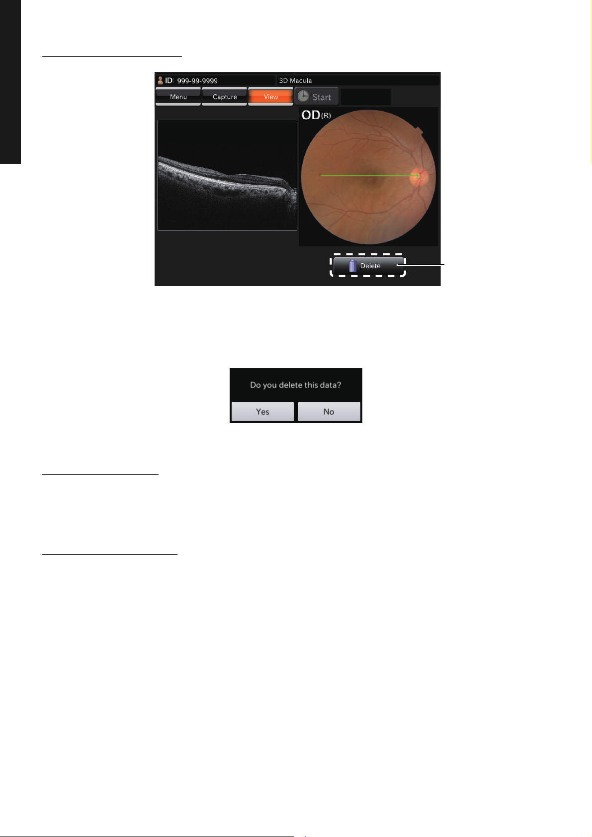
[Delete] button
DELETING DATA
DELETING DATA
Tap the [Delete] button while the preview screen is being displayed. The following check message is
displayed. Tap [Yes], and the data that is displayed on the preview screen is deleted.
When color fundus photography is set to OFF or when the instrument without the fundus photography
function is used, the color fundus photography image is changed to the IR fundus photography image.
SAVING DATA
Data is saved on the personal computer. For details, refer to the instruction manual (for software).
PRINTING DATA
Data is printed on the personal computer. For details, refer to the instruction manual (for software).
48
BASIC OPERATIONS
Page 51

HOW TO FINISH
POWER SWITCH
POWER SWITCH
Finishing the personal computer
1 Finish this software.
2 Turn off the personal computer according to its regular finish method.
Finishing the instrument
1 Turn OFF ( ) the of the instrument.
2 Using the control lever, move the instrument body to the position just above the base.
3 Turn the Base clamping knob clockwise and apply the brake to prevent the base from moving
suddenly.
• To prepare for next photography, turn the control lever and move the instrument body to the center position. The vertical position mark indicates the
standard for the instrument's vertical center position.
• When the instrument is not in use for a long time, unplug the power cords of
NOTE
the instrument, external recording device and others from the outlet and
remove the cords from each device.
• This instrument adopts "RESET FROM POWER SAVE STATE" (P.32). If you
use the instrument continually all day, it is recommended to use it without turn-
ing off the .
BASIC OPERATIONS
HOW TO FINISH
49
BASIC OPERATIONS
Page 52
OBJECTIVE OPERATIONS
COLOR FUNDUS PHOTOGRAPHY BUTTON
Color fundus photography button
COLOR FUNDUS PHOTOGRAPHY
• Caution in photography
Under the following photography conditions, there is a bright spot on the center of the picture.
• The patient's pupil is small. (This condition includes the case of "When the
small pupil diaphragm is set to ON".)
• The flash level is high.
NOTE
Selecting the capture icon
• Alignment is not adjusted properly.
To improve these conditions, carry out the following operations.
• Darken the room to enhance dilation.
• Adjust alignment for the position where it is most difficult to see flare on the
monitor screen.
• Set the lowest flash level as far as circumstances allow.
Then, take a picture.
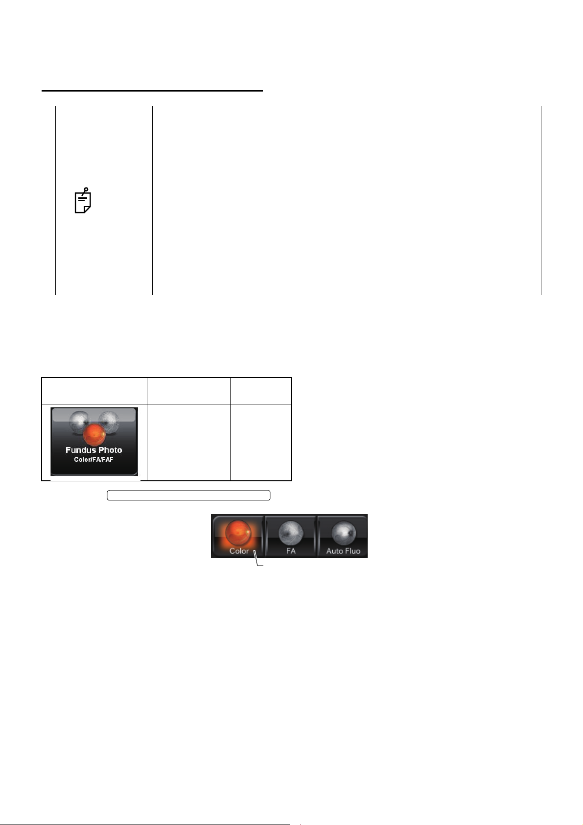
On the capture icon selection screen, which is the initial screen, select the fundus photography capture
icon.
Icon Capture icon
Fundus Photo Center
Select the .
Fixation
position
Setting up the patient
Refer to "Setting up the patient" on page 37.
50
OBJECTIVE OPERATIONS
Page 53

Setting the picture position
INTERNAL FIXATION TARGET POSITION SELECTOR BUTTON
INTERNAL FIXATION TARGET POSITION SELECTOR BUTTON
EXTERNAL FIXATION TARGET SELECTOR BUTTON
Internal fixation target position selector button
Tapping the on Area 2 of the photography screen
(OCT photography), set the picture position. Each time you press the
, the picture position is changed to "C" (the middle
position of optic disc and macula), "M" (macula center) and "D" (optic disc center) in this order. Set the
picture position to "C" for the middle position of optic disc and macula, "M" for macula, and "D" for optic
disc. To take a picture of anterior segment, set to "External fixation target" by the
on the control panel.
Setting the illumination level
Set the illumination level by touching the [Illumination level] display on the fundus/anterior segment live
image area. Refer to "Setting the illumination level" on page 40.
Setting the flash level
Set the flash level by touching the [Flash level] display on the fundus/anterior segment live image area.
Refer to "Setting the flash level" on page 40.
In the color fundus photography (normal), the flash level is automatically
NOTE
changed to the recommended setting (4.0W·s when the reference value is "0").
For details, refer to "RELATION BETWEEN THE SETTING OF THE ILLUMINATION/FLASH LEVEL AND MAXIMUM RADIANCE" on P.118.
Changing the diopter compensation lens
Turn the diopter compensation lens selector to change the diopter compensation lens to "0". Refer to
"Changing the diopter compensation lens" on page 41.
51
OBJECTIVE OPERATIONS
Page 54

Alignment and photography
SMALL PUPIL DIAPHRAGM SELECTOR BUTTON
SMALL PUPIL DIAPHRAGM SELECTOR BUTTON
The alignment operation is done with the control lever.
For details about movement/adjustment of the instrument body with the control lever, see the "Alignment and photography" on page 42.
1 Hold the control lever and pull the instrument body to the utmost limit toward the patient.
2 Using the control lever, move the instrument body right and left, up and down to display the
patient's eye at the center of the fundus/anterior segment live image area.
3 Align the ( ) scale with the patient’s pupil on the touch display of the instrument body. Make sure
that the patient’s pupil is larger than the ( ) scale. Even if the pupil is smaller than the ( ) scale,
the small pupil diaphragm is automatically set to "ON" during photography by setting the automatic small pupil (diaphragm) function, which is usable only for the color fundus photography.
So, it is not necessary to set it to "ON" by the on the control panel.
• For dilation, refer to the "MEMO" on page 43.
• If the pupil diameter is almost the same size of the ( ) scale, the automatic
small pupil (diaphragm) function does not work though the automatic small
NOTE
pupil (diaphragm) function is set and, under this condition, the instrument
takes a picture. If you are not satisfied with the image in this case, set the
to "ON" on the control panel and take
a picture again. Then, compare the image with the first one.
4 Push in the instrument body slowly toward the patient side, and the fundus image appears on the
fundus/anterior segment live image area.
5 The ( ) scale on the touch display moves to the alignment position corresponding to the picture
position.
6 Ask the patient to see the green light (internal fixation target).
7 As watching the image on the touch display, adjust its brightness by touching the [Illumination
level] display on the touch display.
NOTE
For setting the illumination level, refer to "Setting the illumination level" on page
40.
8 Push in the instrument body straight. After the alignment bright spot and split lines appear, the
auto focus function changes the split lines into one line automatically.
9 Using the control lever, change the alignment bright spots into one spot and put it into the ( )
scale.
52
OBJECTIVE OPERATIONS
Page 55
10 When the positional relation between the instrument body and the patient's eye is proper for pho-
PHOTOGRAPHY BUTTON
Preview display
FLASH LEVEL DISPLAY
tography after putting the alignment bright spot into the ( ) scale, the color fundus photography is
automatically done by the auto shoot function. Ask the patient not to blink and not to move his/
her eyes during photography.
• If the patient blinks right before the color fundus photography, the automatic
blink detection function stops the photography. Start the procedure again from
alignment and take a picture.
NOTE
• When the auto shoot function is OFF or when the diopter compensation lens
is set to others except "0", the instrument does not take a picture automati-
cally. Press the to take a color picture of fundus.
11 Each time you take a picture, the photographed image is displayed on the preview area at the left
side of the screen.
NOTE
• If the light intensity of the photographed image is not correct, touch the
on the photography screen to adjust the light intensity.
Then, repeat alignment and photography. Refer to "Setting the flash level" on
page 40.
• Take a picture by repeating Procedure 1 - 11 if necessary.
53
OBJECTIVE OPERATIONS
Page 56

FUNDUS PERIPHERAL PHOTOGRAPHY
PERIPHERAL PHOTOGRAPHY SELECTOR
Peripheral photography
selector button
8×Window for
anterior fixation
Caution in photography
Under the following photography conditions, there is a bright spot on the center of the picture.
• The patient's pupil is small. (This condition includes the case of "When
the small pupil diaphragm is set to "ON")
• The flash level is high.
NOTE
Selecting the photography icon
After selecting the fundus image capture icon, select the button.
• Alignment is not adjusted properly.
To improve these conditions, carry out the following operations.
• Darken the room to enhance dilation.
• Adjust alignment for the position where it is most difficult to see flare on
the monitor screen.
• Set the lowest flash level as far as circumstances allow.
Then, take a picture.
Setting the picture position
• The fixation position can be changed in nine directions with the following buttons. On the button, the
capture count at each fixation position is displayed. The LED of the anterior segment fixation hole is
turned on because it corresponds with each button.
54
OBJECTIVE OPERATIONS
Page 57

• You can set the following six fixation patterns on the setting menu. Refer to "PAGE 2: Photography
Fixation pattern Lighting place
4X
4+
5X
5+
8
9
357
9
246813579
12468
23456789123456789
Setting" on P.82.
NOTE
In peripheral photography, the automatic small pupil function does not work.
Setting up the patient and capturing
Refer to "Setting up the patient" on page 37.
OBJECTIVE OPERATIONS
55
Page 58
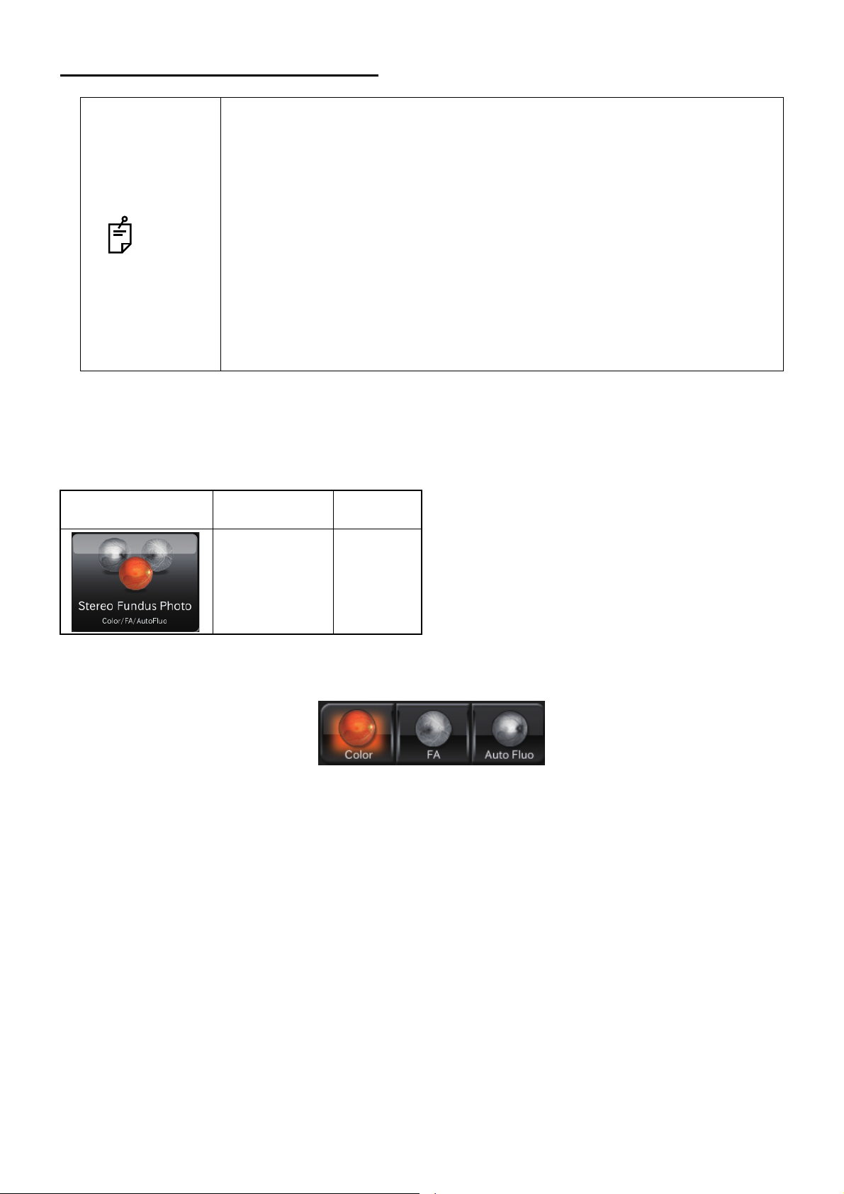
STEREOSCOPIC PHOTOGRAPHY
Caution in photography
Under the following photography conditions, there is a bright spot on the center of the picture.
• The patient's pupil is small. (This condition includes the case of "When
the small pupil diaphragm is set to "ON".)
• The flash level is high.
NOTE
Selecting the capture icon
On the capture icon selection screen, which is the initial screen, select the fundus photography capture
icon.
• Alignment is not adjusted properly.
To improve these conditions, carry out the following operations.
• Darken the room to enhance dilation.
• Adjust alignment for the position where it is most difficult to see flare on
the monitor screen.
• Set the lowest flash level as far as circumstances allow.
Then, take a picture.
Icon Capture icon
Stereoscopic
Photo
For others except color photography, it is also possible to select the icon and perform stereoscopic
photography.
Fixation
position
Disc
Setting the illumination level
Set the illumination level by touching the [Illumination level] display on the fundus/anterior segment live
image area. Refer to "Setting the illumination level" on page 40.
Setting the flash level
Set the flash level by touching the [Flash level] display on the fundus/anterior segment live image area.
Refer to "Setting the flash level" on page 40.
Changing the diopter compensation lens
Turn the diopter compensation lens selector to change the diopter compensation lens to "0". Refer to
"Changing the diopter compensation lens" on page 41.
56
OBJECTIVE OPERATIONS
Page 59
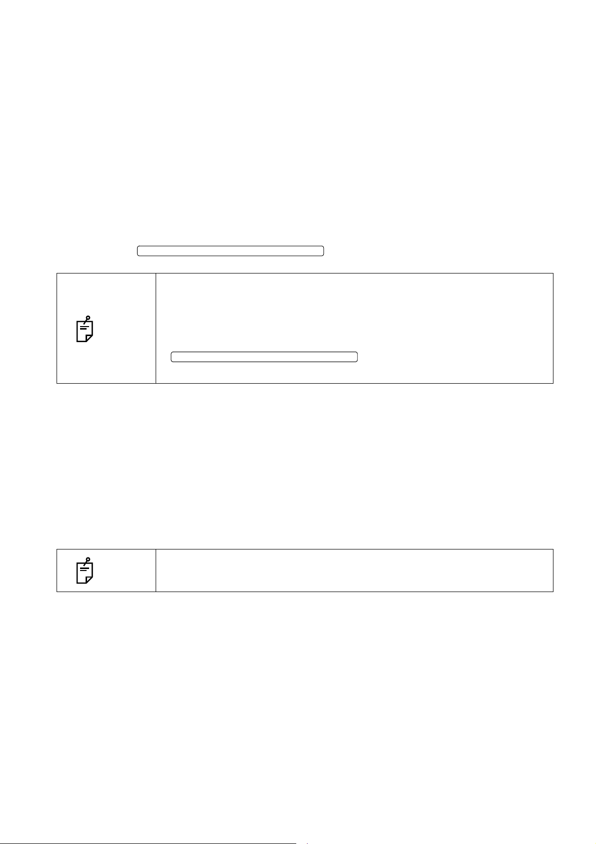
Alignment and photography
SMALL PUPIL DIAPHRAGM SELECTOR BUTTON
SMALL PUPIL DIAPHRAGM SELECTOR BUTTON
The alignment operation is done with the control lever.
For details about movement/adjustment of the instrument body with the control lever, see the "Alignment and photography" on page 42.
1 Hold the control lever and pull the instrument body to the utmost limit toward the patient.
2 Using the control lever, move the instrument body right and left, up and down to display the
patient's eye at the center of the fundus/anterior segment live image area.
3 Align the ( ) scale with the patient's pupil on the touch display. Make sure that the patient's pupil
is larger than the ( ) scale. Even if the pupil is smaller than the ( ) scale, the small pupil diaphragm is automatically set to "ON" during photography by setting the automatic small pupil (diaphragm) function, which is usable only for the color fundus photography. So, it is not necessary
to use the on the control panel.
• For dilation, refer to "MEMO" on page 43.
• If the pupil diameter is almost the same size of the ( ) scale, the automatic
small pupil (diaphragm) function does not work though the automatic small
NOTE
pupil (diaphragm) function is set and, under this condition, the instrument
takes a picture. If you are not satisfied with the image in this case, set the
to "ON" on the control panel and take
a picture again. Then, compare the image with the first one.
4 Push in the instrument body slowly toward the patient side, and the fundus image appears on the
fundus/anterior segment live image area.
5 The ( ) scale on the touch display moves to the alignment position corresponding to the picture
position.
6 Ask the patient to see the green light (internal fixation target).
7 As watching the image on the touch display, adjust its brightness by touching the [Illumination
level] display on the touch display.
NOTE
For setting the illumination level, refer to "Setting the illumination level" on page
40.
8 Push in the instrument body straight. After the alignment bright spot and split lines appear, the
auto focus function changes the split lines into one line automatically.
57
OBJECTIVE OPERATIONS
Page 60

9 Using the control lever, move the instrument body and put the alignment bright spot into the ( )
STEREOSCOPIC PHOTOGRAPHY SELECTOR BUTTON
Stereoscopic
photography
selector button
PHOTOGRAPHY BUTTON
scale.
• By this operation, focusing and positioning are performed. However, photographing is not performed.
• By this operation, the alignment bright sport is moved to the left.
• When the auto focus function is ON, even if you pull the base unit toward the
patient in stereoscopic photography, the focusing knob is not reset to the initial
position.
• When the auto focus function is OFF, turn the focusing knob to change the
split lines into one line.
NOTE
• When the auto shoot function is OFF or when the diopter compensation lens
is set to others except "0", put the alignment bright spot into the ( ) scale and
then select the .
10 When the positional relation between the instrument body and the patient's eye is proper for pho-
tography after putting the alignment bright spot into the ( ) scale, the fundus photography is automatically done by the auto shoot function. Ask the patient not to blink and not to move his/her
eye during photography.
• If the patient blinks right before the fundus photography, the automatic blink
detection function stops the photography. Start the procedure again from
alignment and take a picture.
NOTE
• When the auto shoot function is OFF or when the diopter compensation lens
is set to others except "0", the instrument does not take a picture automati-
cally. Press the to take a color picture of fundus.
58
OBJECTIVE OPERATIONS
Page 61

11 Each time you take a picture, the photographed image is displayed on the preview area at the
Preview display
FLASH LEVEL DISPLAY
STEREOSCOPIC PHOTOGRAPHY SELECTOR BUTTON
right side of the screen. The alignment bright spot is moved to the left.
• If the light intensity of the photographed image is not correct, touch the
on the photography screen to adjust the light intensity.
Then, repeat alignment and photography. Refer to "Setting the flash level" on
page 40.
NOTE
• Take a picture by repeating Procedure 1 - 11 if necessary.
• When you want to take a picture of the same eye again, select the
. The alignment bright spot is
moved from the left to the right and it is possible to carry out the operation of
Procedure 10.
12 Operate the control lever so that the moved alignment bright spot may be put into the ( ) scale.
13 When the positional relation between the instrument body and the patient's eye is proper for
photography after putting the alignment bright spot into the ( ) scale, the fundus photography is
automatically done by the auto shoot function. A picture of another eye is taken and the preview
screen appears.
NOTE
When the auto focus function is OFF, the operation is the same as the photography at the right eye.
59
OBJECTIVE OPERATIONS
Page 62
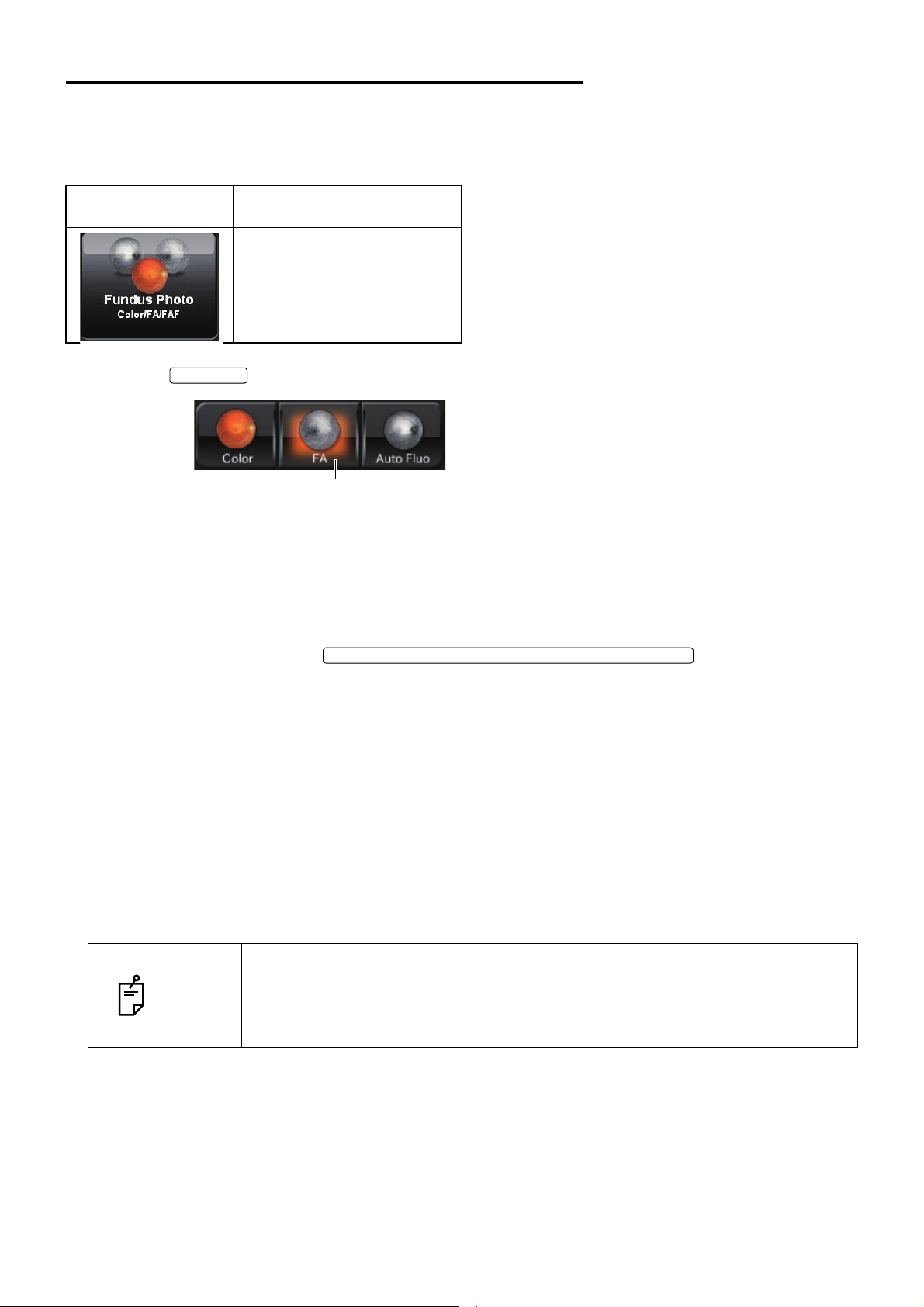
FA PHOTOGRAPHY (DRI OCT-1 Model Triton plus)
FA BUTTON
[FA] button
INTERNAL FIXATION TARGET POSITION SELECTOR BUTTON
Selecting the capture icon
On the capture icon selection screen, which is the initial screen, select the fundus photography capture
icon.
Icon Capture icon
Fundus Photo Center
Select the .
Setting up the patient
Refer to "Setting up the patient" on page 37.
Setting the picture position
Fixation
position
If necessary, by touching the , change the internal
fixation target position (one of "D", "C" and "M") to "D", "C", "M" or "External fixation target" and set the
desired picture position.
Setting the illumination level
Set the illumination level by touching the [Illumination level] display on the fundus/anterior segment live
image area. Refer to "Setting the illumination level" on page 40.
Setting the flash level
Set the flash level by touching the [Flash level] display on the fundus/anterior segment live image area.
Refer to "Setting the flash level" on page 40.
In FA photography, the flash level is automatically changed to the recom-
NOTE
mended setting (32W·s with the reference value "0"). For details, refer to
"RELATION BETWEEN THE SETTING OF THE ILLUMINATION/FLASH
LEVEL AND MAXIMUM RADIANCE" on page 118.
Changing the diopter compensation lens
Turn the diopter compensation lens selector to change the diopter compensation lens to "0". Refer to
"Changing the diopter compensation lens" on page 41.
60
OBJECTIVE OPERATIONS
Page 63
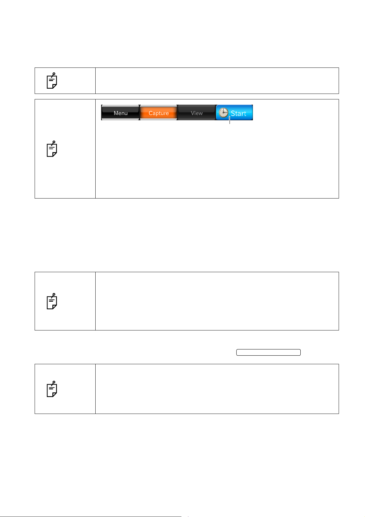
Preparation for the patient
Timer button
PHOTOGRAPHY BUTTON
1 Drop mydriatic into the patient's eye to dilate his/her eye fully.
2 Prepare for intravenous injection of fluorescein.
NOTE
NOTE
Alignment and photography
Refer to "Alignment and photography" on page 52.
Before performing the intravenous injection of fluorescein, check if it is possible
to take a correct picture.
Timer button is used to measure the elapsed time after injecting fluorescein.
Carry out the intravenous injection of fluorescein and immediately touch the
timer button. The timer counts time. The displayed characters are changed
from "START" to "STOP". To stop the timer, touch the characters "STOP".
Then, the message to recheck for the timer stop appears. Touch the [Yes] button on the message. You can also change the setting not to display the recheck
message.
1 Carry out the intravenous injection of fluorescein and at the same time touch the timer button on
the touch display to start the timer.
• After the timer starts to count, only for 20 seconds, the buzzer beeps every
second.
NOTE
• The results of FA photography are influenced by the injection amount and time
of fluorescein, etc.
• When using the timer, the timer count is displayed on all the photographed
images.
2 Make sure that the alignment bright spots are changed into one spot and it is in the ( ) scale and
that the split lines are changed into one line. Then, press the .
• In FA photography, the auto shoot function and auto small pupil function can-
not be used.
NOTE
• After the timer starts to count, by pressing the photography button for a while,
the continuous photography at intervals of 1.5 seconds starts. When releasing the photography button, the continuous photography stops.
61
OBJECTIVE OPERATIONS
Page 64

3 Each time you take a picture, the photographed image is displayed on the preview area at the left
FLASH LEVEL DISPLAY
side of the screen.
If the light intensity of the photographed image is not correct, touch the
NOTE
Then, repeat alignment and photography. Refer to "Setting the flash level" on
page 40.
on the photography screen to adjust the light intensity.
4 Take a picture by repeating Procedure 1 - 3 if necessary.
NOTE
After the timer starts to count, even if the photography mode is changed, the
timer stays on the screen and keeps counting.
62
OBJECTIVE OPERATIONS
Page 65

FAF PHOTOGRAPHY (DRI OCT-1 Model Triton plus)
Auto Fluo BUTTON
[Auto Fluo] button
INTERNAL FIXATION TARGET POSITION SELECTOR BUTTON
Selecting the capture icon
On the capture icon selection screen, which is the initial screen, select the fundus photography capture
icon.
Icon Capture icon
Fundus Photo Center
Select the .
Fixation
position
Setting up the patient
Refer to "Setting up the patient" on page 37.
Setting the picture position
If necessary, by touchiing the , change the internal fixation target position (one of “D”,”C” and ”M”) to “D”,”C”,”M” or “External fixation target” and set the
desired picture position.
Setting the illumination level
Set the illumination level by touching the [Illumination level] display on the fundus/anterior segment live
image area. Refer to "Setting the illumination level" on page 40.
Setting the flash level
Set the flash level by touching the [Flash level] display on the fundus/anterior segment live image area.
Refer to "Setting the flash level" on page 40.
In the FAF photography, the flash level is automatically changed to the recom-
NOTE
mended setting (212W·s when the reference value is "0"). For details, refer to
"RELATION BETWEEN THE SETTING OF THE ILLUMINATION/FLASH
LEVEL AND MAXIMUM RADIANCE" on page 118.
Changing the diopter compensation lens
Turn the diopter compensation lens selector to change the diopter compensation lens to "0". Refer to
"Changing the diopter compensation lens" on page 41.
63
OBJECTIVE OPERATIONS
Page 66

Preparation for the patient
POWER SWITCH
1 Drop mydriatic into the patient’s eye to dilate his/her eye fully according to the need.
Alignment and photography
Refer to "Alignment and photography" on page 52.
• To prepare for next photography, turn the control lever and move the instru-
ment body to the center position. The vertical position mark indicates the
standard for the instrument's vertical center position.
• When the instrument is not in use for a long time, unplug the power cords of
NOTE
the instrument, external recording device and others from the outlet and
remove the cords from each device.
• This instrument adopts "RESET FROM POWER SAVE STATE" (P.32). If you
use the instrument continually all day, it is recommended to use it without turning off the .
64
OBJECTIVE OPERATIONS
Page 67
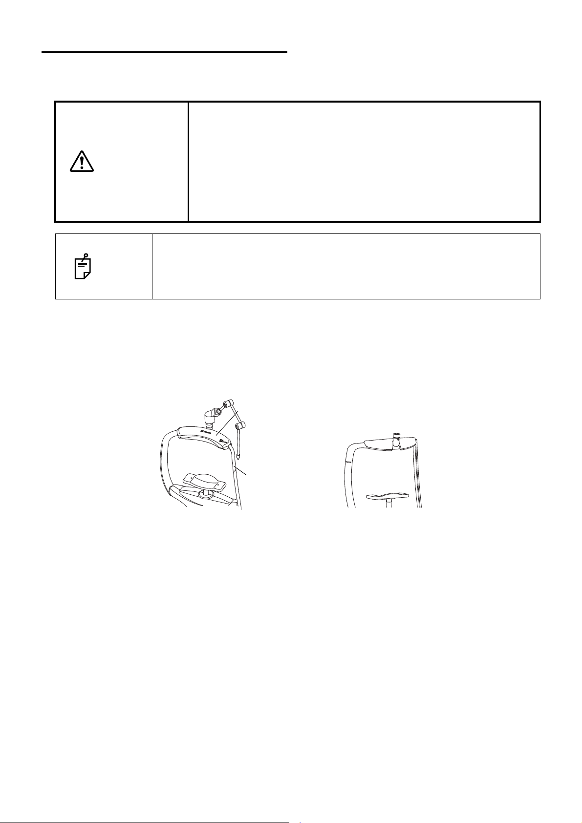
ANTERIOR SEGMENT TOMOGRAPHY
Attachment for anterior segment
Forehead rest base
To take a tomogram of anterior segment, mount the attachment for anterior segment AA-1, which is an
optional accessory. (Refer to P.120.)
• To avoid injury of the patient, be careful not to bump the patient's eye
or nose with the instrument when operating the touch display.
• Mount the attachment for anterior segment on the forehead rest
securely. Otherwise, the attachment may come off during photogra-
CAUTION
• Mount the attachment for anterior segment on the forehead rest securely. If
NOTE
• Do not bend the attachment for anterior segment forcedly. It may be broken
not, the anterior segment photography is not possible.
or deformed.
phy and the patient may be injured.
• To avoid injury of the patient, be careful not to bump the patient's eye
or nose with the anterior segment lens unit when operating the control
lever.
Mounting the attachment for anterior segment
Mount the attachment for anterior segment onto the forehead rest base, as if the attachment covers the
base as shown below. After mounting, make sure that the attachment for anterior segment is fixed on
the forehead rest base. Then, take a picture of anterior segment.
65
OBJECTIVE OPERATIONS
Page 68

Mounting the anterior segment lens unit
Insert the anterior segment lens unit along three grooves on the instrument body. Turn the lens unit in
the arrow direction to fix it.
Insert the anterior segment lens unit into the instrument body straight. If you
NOTE
insert the anterior segment lens unit slantingly into the instrument body, the
instrumen's lens may be damaged.
Selecting the capture icon
On the capture icon selection screen, which is the initial screen, select the anterior segment tomogram
capture icon.
Capture Icon Capture Icon name Scan size
Line:
Anterior segment (H)
Line:
Anterior segment (V)
Radial:
Anterior segment
3D:
Anterior segment
3mm
6mm 1024×12 Corneal top Cornea 4
3×3mm 512×256 External Cornea -
Scan
resolution
1024H/
1024V
Fixation
position
External Deep pos 64
OCT Focus
Position
Over Scan
Count
66
OBJECTIVE OPERATIONS
Page 69

Setting up the patient
Refer to "Setting up the patient" on page 37.
Setting the picture position
Operate the arm of the external fixation target to guide the patient's eye to the correct position.
67
OBJECTIVE OPERATIONS
Page 70
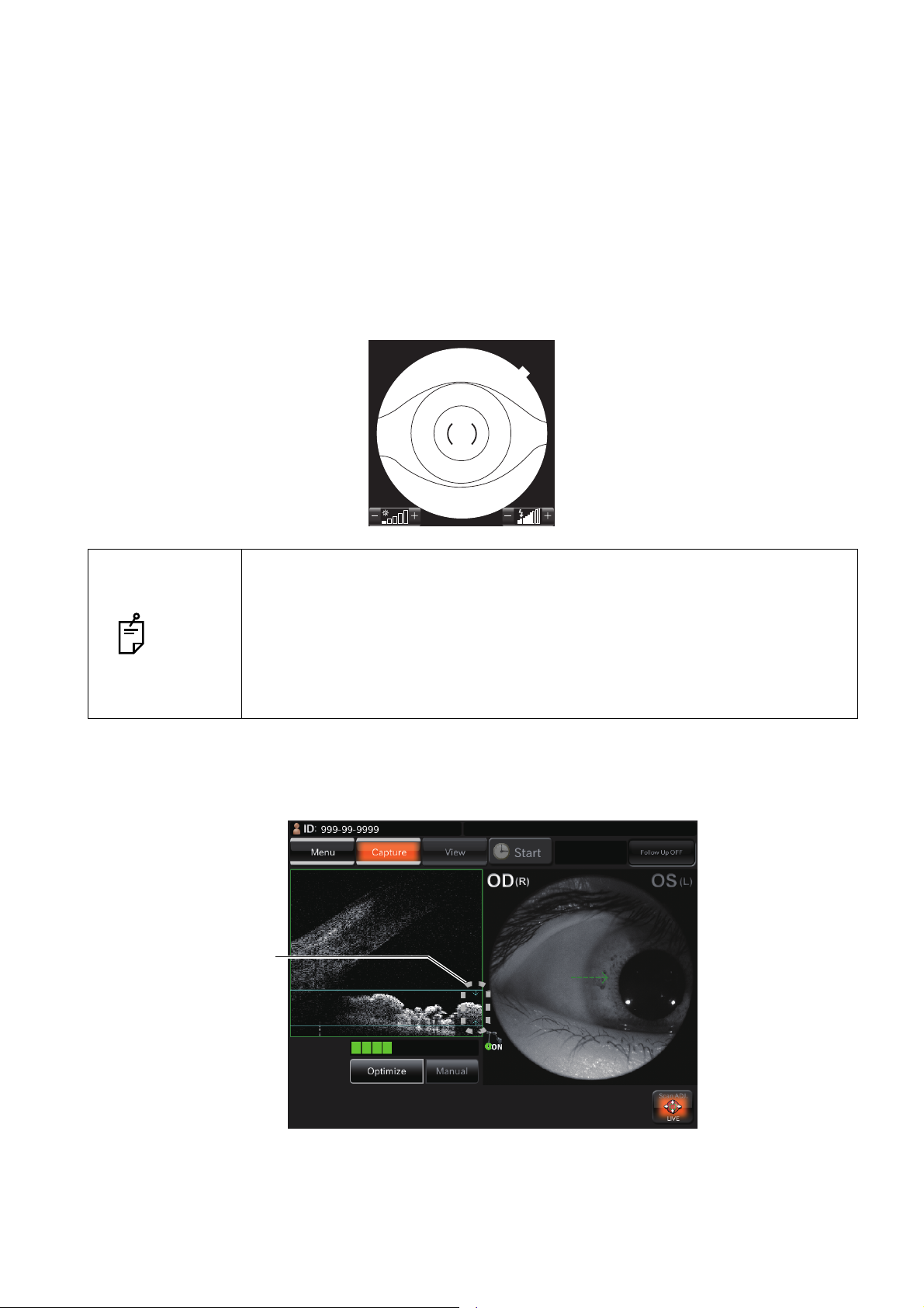
Alignment and photography
5
OD(R) OS(L)
1
Optimal display
position frame
The alignment operation is done with the control lever.
For details about movement/adjustment of the instrument body with the control lever, see "Alignment
and photography" on page 42.
1 Hold the control lever and pull the instrument fully toward the operator.
2 Using the control lever, move the instrument body right and left, up and down to display the
patient's eye at the center of the fundus/anterior segment live image area.
3 Push in the instrument body slowly toward the patient side until the tomogram of the anterior seg-
ment is displayed on the OCT live image area of the touch display.
• When the anterior segment tomogram icon is selected, the alignment bright
spot and split lines are not displayed.
• When the anterior segment tomogram icon is selected, "Auto Z (Z Lock)" is
NOTE
invalidated (OFF).
• When photographing, be careful to keep eyelashes out of the picture. The
eyelashes in the picture will cause the lowered accuracy for overlapping tomograms ("Over Scan Count" function).
4 In case of "OCT Focus Position: Deep pos", move the instrument body back and forth and adjust
its position finely so that the tomogram display position may be aligned with the optimal display
position frame, which is displayed at the right end on the OCT live image area.
68
OBJECTIVE OPERATIONS
Page 71
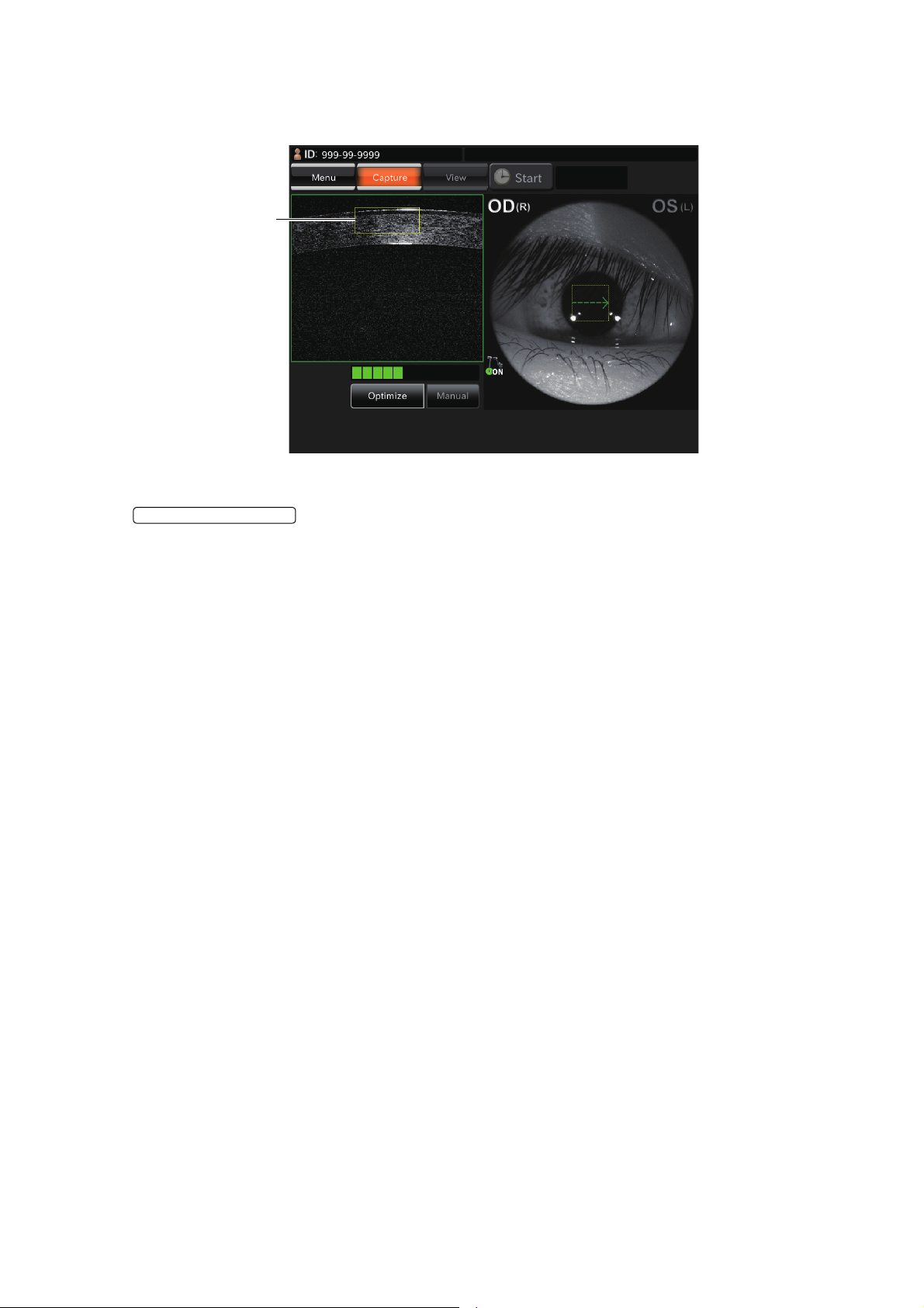
In case of "Radial: Anterior segment" and "3D: Anterior segment" (OCT Focus Position: Cornea),
Alignment optimal
position frame
PHOTOGRAPHY BUTTON
move the instrument body back and forth and adjust its position finely so that the tomogram may
be displayed within the alignment optimal position frame on the OCT live image area.
5 Make sure that the tomogram is clearly displayed. Then, ask the patient not to blink and tap the
.
69
OBJECTIVE OPERATIONS
Page 72
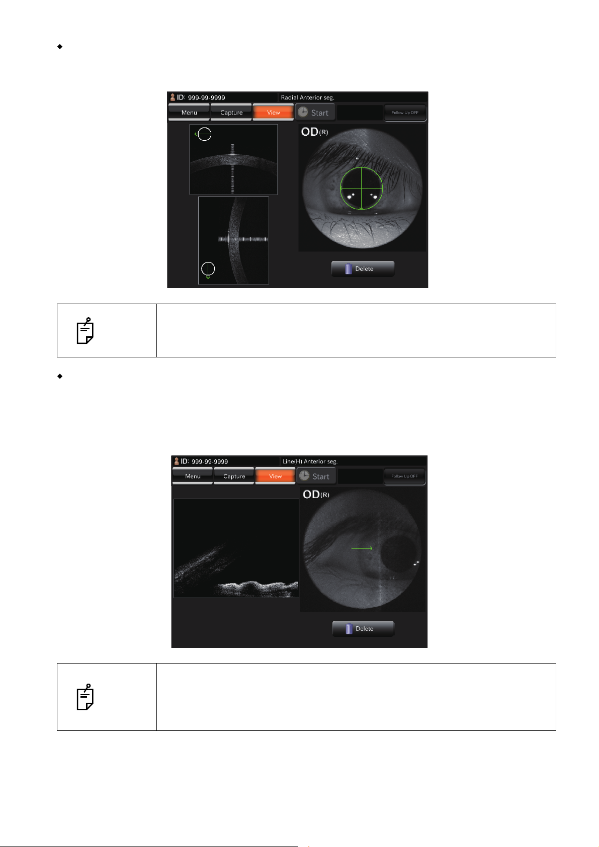
When taking a picture of cornea
Select the "Radial: Anterior segment" and move the instrument body until the cornea tomogram is displayed
near the optimal display position frame on the top of the screen.
Take a picture of cornea where the signal of one vertical line displayed on the
NOTE
cornea tomogram is strong. This is the status where the scan center is fit to the
cornea vertex.
When taking a picture of anterior chamber angle
Select "Line: Anterior segment". Push in the instrument body, which is in the pulled status. You
will see the anterior chamber angle which is upside-down. Push in the instrument body until the
tomogram of the anterior chamber angle is displayed near the optimal display position frame on
the bottom of the screen.
NOTE
70
OBJECTIVE OPERATIONS
When moving the tomogram of the anterior chamber angle to the lower end of
the screen, the tomogram has many folded parts. Move the instrument body to
move the anterior chamber angle display position upward a little. Then, take a
picture.
Page 73

When changing the scan line angle in "Line" anterior segment photography
Scan position button
SET UP BUTTON
Tap the scan position button, and the rotation button is displayed. Tap the rotation button, and you
can change the scan line angle by 15 degrees. Tap the [RESET] button, and you can return the
angle to the default.
When taking a picture of crystalline lens
Change the setting to [Cornea] for "OCT Focus Position" of "Line: Anterior segment" by using the
on the capture icon selection screen. Then, select this capture icon. Move the
instrument body until the tomogram of crystalline lens is displayed near the optimal display position frame on the top of the screen.
71
OBJECTIVE OPERATIONS
Page 74
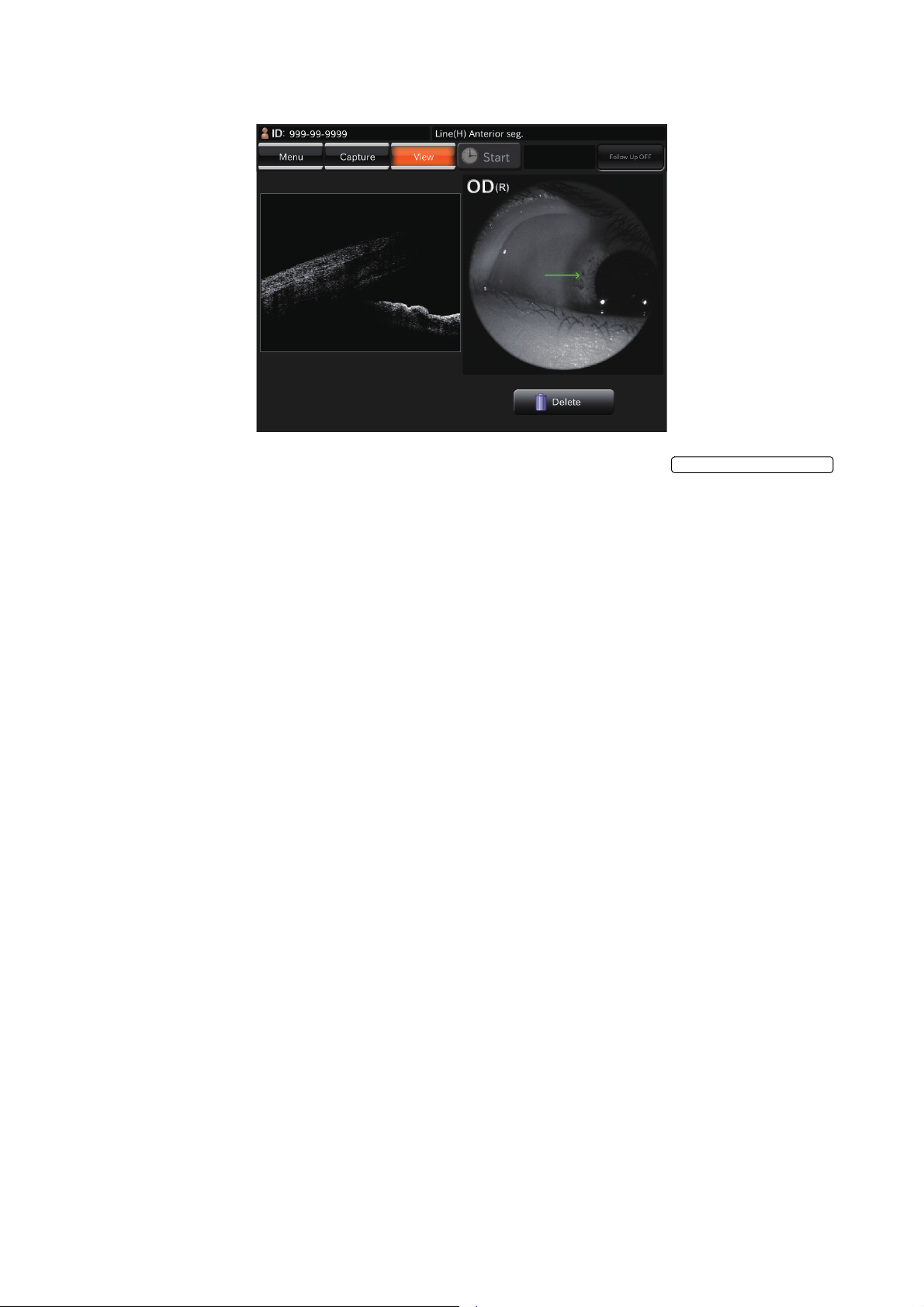
6 Each time you take a picture, the preview screen is displayed.
PHOTOGRAPHY BUTTON
7 Tap the photography mode button at the top on the screen or the to
access the Monitor screen again. Take a picture by repeating Procedure 1 - 6 if necessary.
72
OBJECTIVE OPERATIONS
Page 75
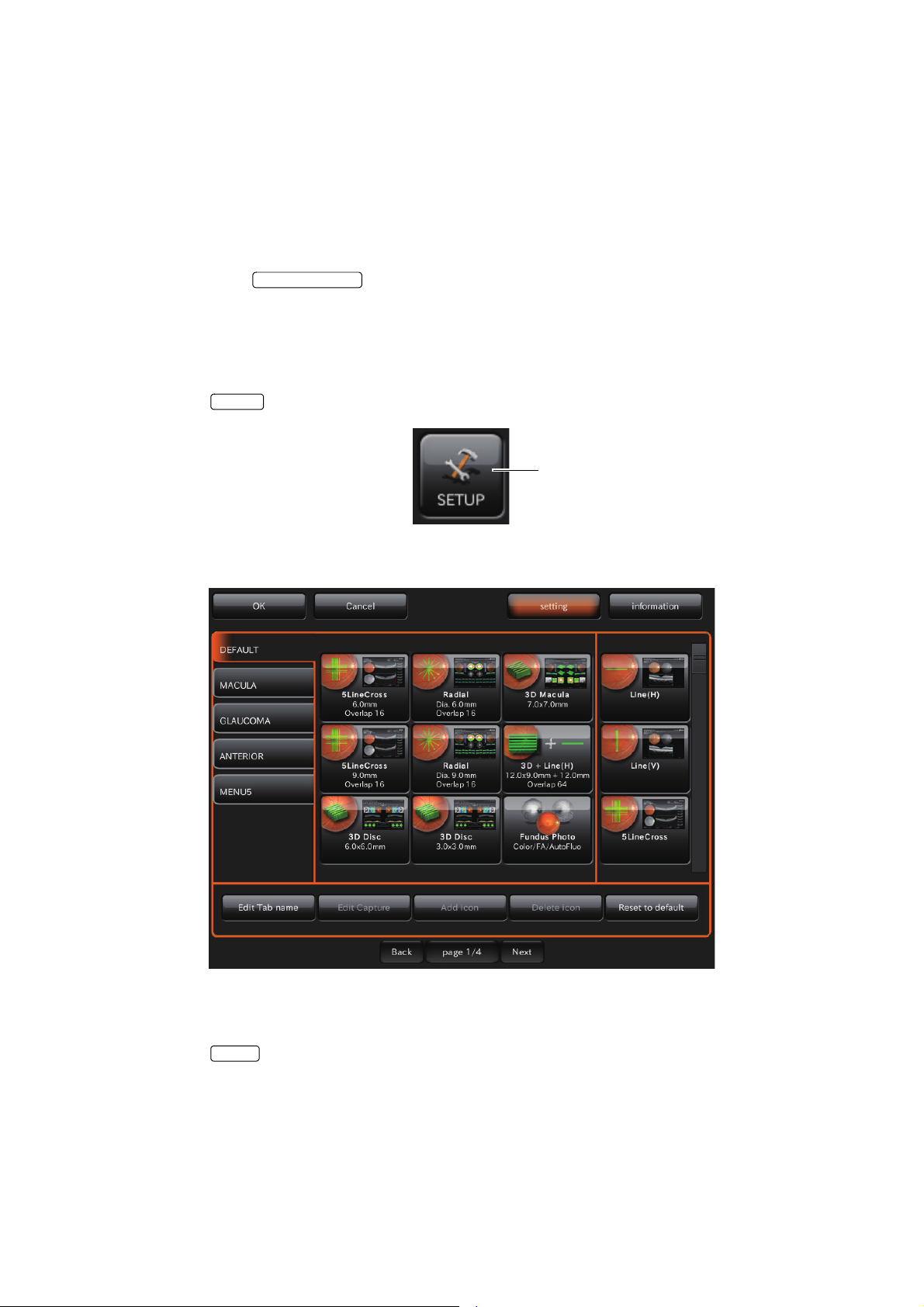
DETAILS OF THE SETTING MENU
POWER SWITCH
SET UP
[SET UP] (setting menu) button
Cancel
On the setting menu screen, you can set a variety of data.
Preparation for setting
1 Check the power cord connection.
For details, see "CONNECTING THE POWER CORD" on page 30.
2 Turn ON (I) the of the instrument.
Displaying the setting menu screen
1 Check the capture icon selection screen, which is the initial screen.
2 Press the button on the capture icon selection screen.
3 Check the setting menu screen.
Returning to the capture icon selection screen:
1 Press the button.
2 Return to the capture icon selection screen.
DETAILS OF THE SETTING MENU
73
Page 76

PAGE 1: Capture Icon Setting
On the "PAGE 1" screen, set the icon display for the capture icon, which is displayed on the capture
icon selection screen, and the parameters for each capture icon. For details on the buttons, refer to
page 25 and page 27.
• PAGE 1: Initial screen
• How to delete the displayed icon:
1 Tap and select the capture icon to be deleted in the icon layout setting area. (It is highlighted.)
74
DETAILS OF THE SETTING MENU
Page 77

2 Press the button.
Delete icon
3 Make sure that the icon is deleted. The remaining icons are moved to the left side or upper right
corner.
75
DETAILS OF THE SETTING MENU
Page 78

• How to add the displayed icon
Add icon
1 Tap and select the capture icon to be added from the capture icon list. (It is highlighted.)
2 Press the button.
76
DETAILS OF THE SETTING MENU
Page 79

3 Make sure that the icon is added.
77
DETAILS OF THE SETTING MENU
Page 80

• How to check and change the parameters for the icons:
Edit Capture
1 Tap and select the icon of the capture icon for which the parameters should be checked and
changed in the icon layout setting area. (It is highlighted.)
2 Press the button at the bottom of the screen.
78
DETAILS OF THE SETTING MENU
Page 81
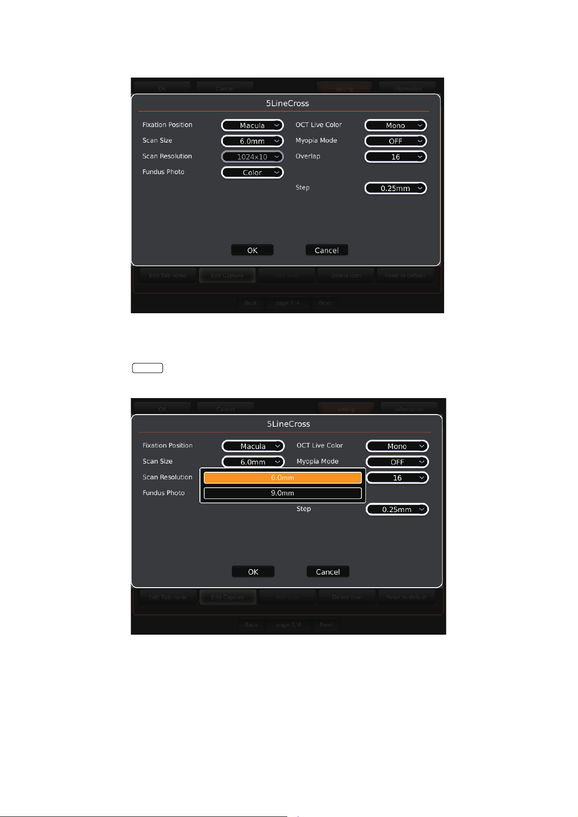
3 The parameter setting screen appears.
Cancel
4 Tap the item button whose setting should be changed. The selectable item values are displayed.
Tap and change the value to the desired one. Press the [OK] button to decide the change. If you
press the button, the value before changing is set again and the system exits from the
parameter setting screen.
79
DETAILS OF THE SETTING MENU
Page 82

Item buttons for setting parameters
(1) Scan Pattern
Scan pattern means the shape or kind to be scanned. It is classified into the following 5 kinds:
Line: Scans linearly.
3D: You can scan the range (Scan Size) with the horizontally-set resolution (Scan
Resolution) and display the scanned object as a stereograph.
3D Wide (H): You can scan the range (Scan Size) with the horizontally-set resolution (Scan
Resolution) and display the scanned object as a stereograph.
5 Line Cross: Scans with five lines in each of horizontal and vertical directions at regular inter-
vals crosswise.
Radial: Scans radially with the set radial lines (Radial Scan Count).
(2) Scan Size
"Scan Size" means the length or range to scan.
(3) Scan Resolution
"Scan Resolution" means the data quantity to be read by scanning. In the "Line" and "Radial"
scans, it is the data for one line. In the "3D" scan, it is the data for each side of "Length×Width". As
the scan resolution is higher, a more detailed tomogram can be obtained and at the same time the
data quantity is increased. So, it takes a longer time to process the read data and the saved data is
increased.
(4) Fundus Photography
You can set whether the fundus photography should be done.
This item cannot be set in the instrument without the fundus photography function.
(In DRI OCT-1 Model Triton plus, you can select "Color" and "Auto Fluo".)
(5) Fixation Position
Set the fixation position of the patient. There are five selectable items for setting, "Disc" (optic disc),
"Center", "Macula", "Wide" and "External" (external fixation target). When "Disc" is set, the optic
disc is positioned at the center of the photography screen for the fixation target. When "Center" is
set, the middle position between the optic disc and macula is positioned at the center, and when
"Macula" is set, macula is positioned at the center. When "Wide" is set, the middle position between
"Center" and "Macula" is positioned at the center. When "External" is set, the internal fixation target
is turned off and the external fixation target is used.
(6) Over Scan Count
"Over Scan Count" means the following function: The data is read several times at one position for
one scanned line. Two or more tomograms at one position are obtained and are displayed in the
overlapped status. Consequently the tomogram with better contrast than usual can be obtained.
80
DETAILS OF THE SETTING MENU
Page 83

(7) Myopia mode
In this mode, when taking a tomogram of the fundus of the patient whose eye has excessive myopia
or others, the standard interference position is moved to the inner side than the normal position.
(8) Step
This is valid only when the "5 Line Cross" capture icon is selected, and it means the interval of the
vertical or horizontal five scan lines. The settable range is 0.15mm, 0.20mm, 0.25mm, 0.30mm and
0.35mm.
(9) Re-scan
If the patient blinks and his/her fixation position moves during the scan, the obtained tomogram is
partly deviated or missing. This function automatically detects the deviated or missing data and
scans again. This function can be set only for "3D" and "3D Wide".
(10) OCT Live Color
You can set "color display" or "monochrome display" for the live image.
In the initial setting of this instrument, "monochrome display" is set for all the live images.
81
DETAILS OF THE SETTING MENU
Page 84

PAGE 2: Photography Setting
On the "PAGE 2" screen, you can set a variety of data for photography. For the details on each button,
refer to page 28.
• PAGE 2: Initial screen
On PAGE 2, the items shown in the following table are assigned to the buttons on each layer.
Utility button Item button Item selector button At
shipment
Fixation TYPE
• Changes lighting/blinking of the internal fixation target.
SPEED NORMAL(Hz)
• This is valid when the internal fixation target is set to
"FLICKERING" (Blinking).
• Set the blinking speed for all other states except
when photographing.
SPEED MEASURE(Hz)
• This is valid when the internal fixation target is set to
"FLICKERING" (Blinking).
• Set the blinking speed for photographing.
Brightness
• Sets the brightness of the internal fixation target.
Shape (Default)
• Sets the shape of the internal fixation target.
Screen Display Constant
FLICKERING (Blinking)
CONSTANT (Lighting)
1 – 8 1
1 – 8 2
1 – 10 10
1 dot
4 dot rectangle
4 dot rhomb
×
Cross
Brief
82
DETAILS OF THE SETTING MENU
Page 85

Utility button Item button Item selector button At
shipment
Fundus
Photo
(OCT)
Color
Fundus
Photo
FA/Auto
Fluo
Fundus
Photo
Blink detection Level OFF
LOW
NORMAL
Timer Stop Message OFF
ON
OCT+Color Mode
• Changes the color fundus image quality
(Normal/Low).
Flash Level
(Default Model Triton:3.9Ws Model Triton plus:22Ws)
Gain
(Default Model Triton:4.0Ws Model Triton plus:0Ws)
OCT+Auto Fluo Mode
Flash Level (Default 212Ws) 53.0 – 300.0Ws 212
Gain (Default 12db)
Color Mode Normal
Flash Level
(Default Model Triton:4.0Ws Model Triton plus:22Ws)
Gain (Default 0db)
Flash Level Adjustment (Peripheral) 0 – +4 +1
Flash Level Adjustment (30°Mask) -4 – +4 -1
Flash Level Adjustment (Stereo) -4 – +4 0
Peripheral Photo Pattern
Peripheral Photo Fixation Move Auto
FA Mode
Flash Level (Default 32Ws) 7.9 – 63Ws 32
Gain (Default 12db)
Flash Level Adjustment (Peripheral) 0 – +4 +1
Flash Level Adjustment (Stereo) -4 – +4 0
Auto Fluo Mode
Flash Level (Default 212Ws) 53.0 – 300.0Ws 212
Gain (Default 24db)
Flash Level Adjustment (Peripheral) 0 – +4 +1
Flash Level Adjustment (Stereo) -4 – +4 0
Normal
Low Invasive
1.0 – 16Ws (Model Triton)
5.6 – 89Ws (Model Triton plus)
0
– 24db *1
0
– 24db 12
Low Invasive
4.0Ws (Model Triton)
22Ws (Model Triton plus)
0
– 24db *1
4
X
4
+
5
X
5
+
8
9
Manual
0
– 24db 12
0
– 24db 24
*1
*1
83
DETAILS OF THE SETTING MENU
Page 86

Utility button Item button Item selector button At
shipment
Illumination
Level
OCT Z Lock pos. 1 – 992 *2 400
OCT-FLV ON/OFF ON
OCT Scan (Normal) 1 – 5 4
OCT Scan (Tracking) 1 – 5 4
Fundus Photo 1 – 5 3
Z Lock pos.-3D Wide 1 – 992 *2 400
Z Lock pos. (Myopia mode) 1 – 992 *2 450
Z Lock pos.-3D Wide (Myopia mode) 1 – 992 *2 450
Scan ADJ. Duration Time (Sec) 1, 2, 3, 5 3
OFF
Scan Adjust ON
OFF
*1: For the flash level and Gain of each image quality at shipment, refer to the table below.
Model Triton
Image quality
Settable range Setting at shipment Settable range Setting at shipment
Normal 1.0 - 16W
Low 1.0 - 16W
Model Triton plus
Image quality
Settable range Setting at shipment Settable range Setting at shipment
Normal 5.6 - 89W
Low 5.6 - 89W
*2: Ten keys are displayed.
Flash level Gain
•s4.0W•s0 - 24 0
•s2.0W•s0 - 24 6
Flash level Gain
•s22W•s0 - 24 0
•s11W•s0 - 24 6
84
DETAILS OF THE SETTING MENU
Page 87

PAGE 3: Auto Operation
On the "PAGE 3" screen, set the Auto functions. For details on each button, refer to page 28.
• PAGE 3: Initial screen
On PAGE 3, the items shown in the following table are assigned to the buttons on each layer.
Utility button Item button Item selector
button
Focus ON/OFF OFF
ON
Timeout(Sec) 10
20
30
OCT Capture Focus Type Split *2
OCT
Split+OCT
OCT Capture Focus Type
: SP mode
OCT Capture Focus Type
: Fundus OFF
OCT Capture Additional
Retry
Split *2
OCT
Split+OCT
Split *2
OCT
Split+OCT
ON
OFF
At
shipment
85
DETAILS OF THE SETTING MENU
Page 88

Utility button Item button Item selector
button
Small Pupil *1
• This function is usable only when the color fundus capture icon is selected.
• When the pupil diameter of the patient is small
(pupil diameter is approx. φ4.0mm or less), the
small pupil diaphragm is automatically set and
the instrument takes a color picture of the fundus. After taking a picture, the small pupil diaphragm is automatically removed. When you
set the small pupil diaphragm selector button to
"ON" on the control panel, the above automatic
setting is not done.
Auto Optimize ON/OFF ON
Auto Shoot ON/OFF ON
Auto Tracking ON/OFF ON
Focusing Knob Focus Split
ON/OFF ON
OFF
Magnification Mode 45° Mask
30° Mask
OFF
Auto Z
•Detects the retina position automatically, and
always displays the fundus tomogram clearly
during observation.
Z-lock After AutoZ
•After "Auto Z", the photographed fundus image is
automatically fixed.
Auto Pola
•Adjusts the output sensitivity of the fundus tomogram to the optimum
automatically.
Auto Adjust Z-lock position ON
ON
OFF
ON
OFF
ON
OFF
OFF
OFF
OFF
OCT
Split+OCT
At
shipment
*1: In the instrument without the fundus photography function, this is not displayed.
*2: When "Split" is selected for "OCT Capture Focus Type", you can select "Split", "Split+OCT" and
"OCT".
When "OCT" is selected for "OCT Capture Focus Type", you can select "OCT" only.
When "Split+OCT" is selected for "OCT Capture Focus Type", you can select "Split+OCT" and "OCT".
86
DETAILS OF THE SETTING MENU
Page 89
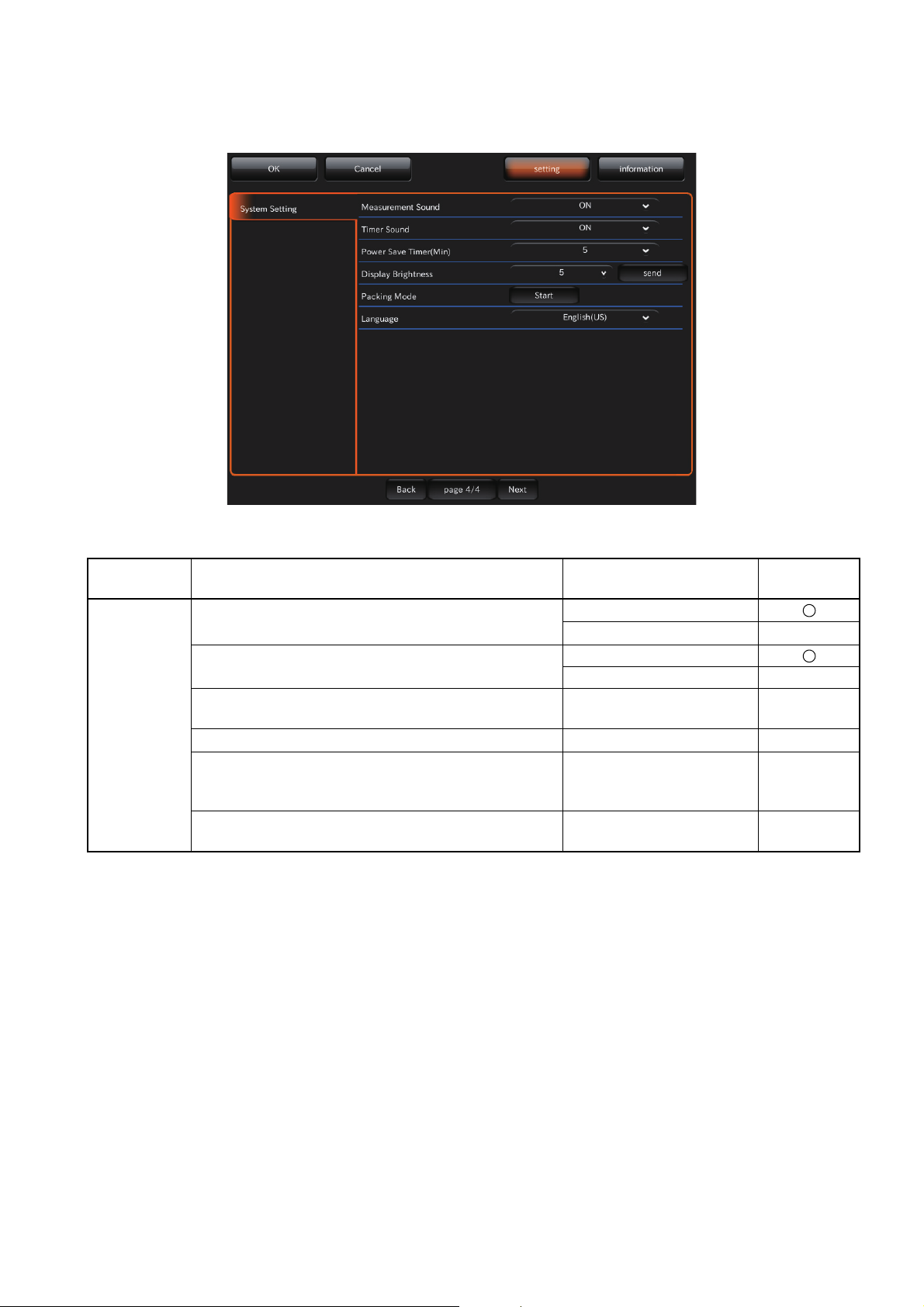
PAGE 4: System Setting
On the "PAGE 4" screen, set the system. For details on each button, refer to page 28.
• PAGE 4: Initial screen
On PAGE 4, the items shown in the following table are assigned to the buttons on each layer.
Utility button Item button Item selector button At
shipment
System
Setting
Measurement Sound
Sets ON/OFF for the measurement sound.
Timer Sound (Only in Model Triton plus)
Sets ON/OFF for the timer sound.
Power Save Timer (Min.)
Sets the time until the power save function is ON.
Display Brightness 1 – 10
Packing Mode
Tap the [Start] button, and the head unit and chinrest move to be in the packaged status.
Language
Sets the display language.
ON
OFF
ON
OFF
0 – 60
(At intervals of 5 minutes)
Start
Japanease (JP) /
English (US)
5
5
-
English
(US)
87
DETAILS OF THE SETTING MENU
Page 90
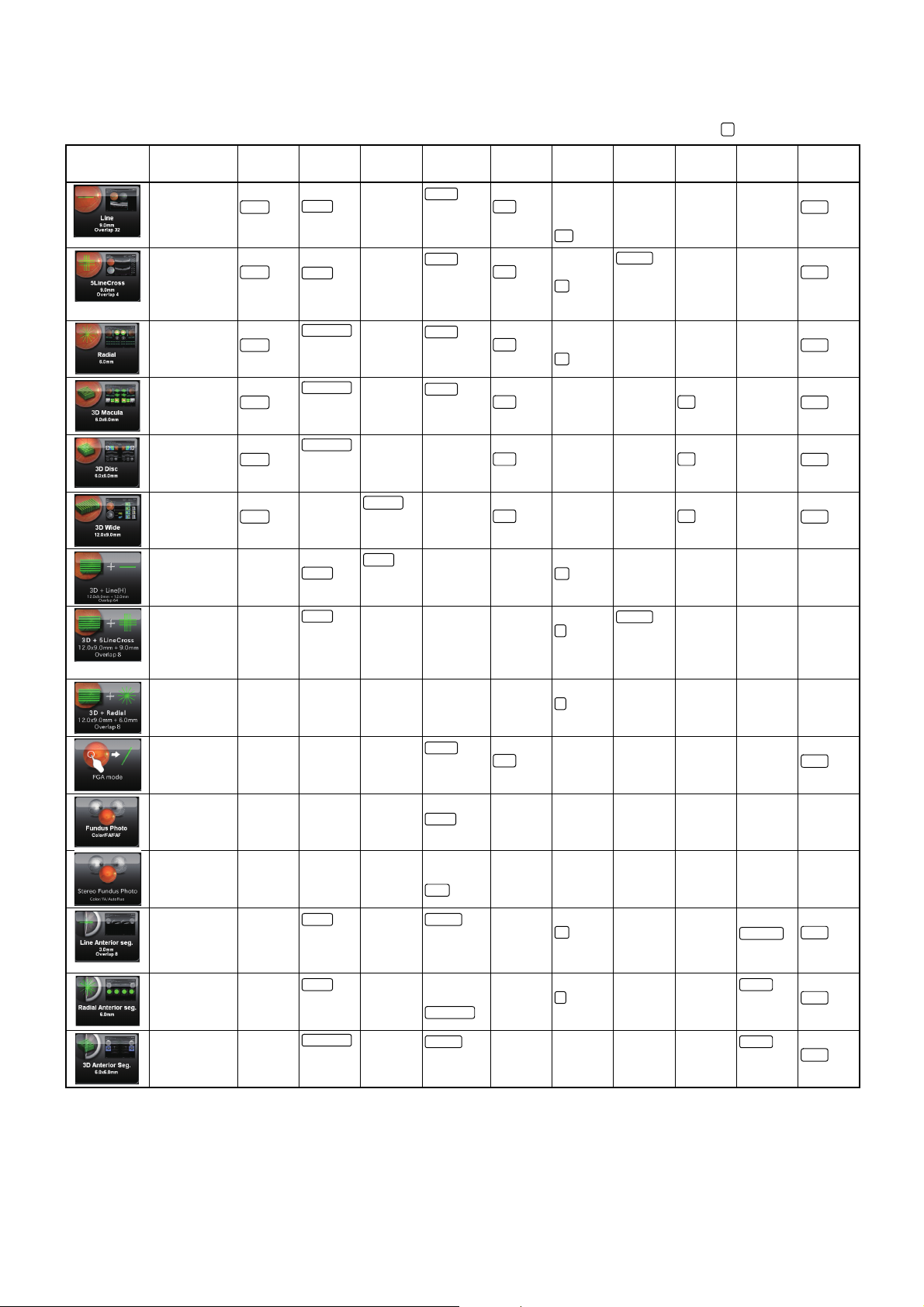
Capture icon protocol
Color
9.0mm
Macula
OFF
128
Mono
Color
6.0mm
Macula
OFF
16
0.15mm
Mono
Color
Dia. 6.0mm
Macula
OFF16Mono
Color
7.0×7.0mm
Macula
OFF
ON
Mono
Color
6.0×6.0mm
OFFONMono
Color
512×256
OFF
ON
Mono
9.0mm
1024H
64
9.0mm
8
0.15mm
8
Macula
OFF
Mono
Center
Disc
3.0mm
External
64
Deep pos.
Mono
6.0mm
Corneal top
4
Cornea
Mono
3.0×3.0mm
External
Cornea
Mono
The following table shows the parameters in each capture icon.
Capture Icon Capture Icon name Fundus
Line (H)/
Line (V)
Photography
OFF
Auto Fluo
Scan Size Scan
12.0mm
6.0mm
Resolution
1024H /
1024V Center
Fixation
Position
Disc
Myopia mode Over Scan
ON Not
Count
8
64
: Initial set value
Step Re-scan OCT Focus
Position
–––Color
OCT live color
5Line
Cross
Radial OFF
3D: Macula OFF
3D: Optic disc OFF
3D Wide (H) OFF
Combination scan:
Line
Combination scan:
5Line Cross
Combination scan:
Radial
OFF
Auto Fluo
Auto Fluo
Auto Fluo
Auto Fluo
Auto Fluo
– 12.0mm
–
– 6.0mm 1024 × 12 Wide – 4 – – – –
9.0mm 1024×10
1024×12
Dia. 9.0mm
512×256
3.0×3.0mm
512×256 Disc ON – – OFF – Color
3.0×3.0mm
12.0×9.0mm
512×128
1024V
6.0mm
1024 × 10 Wide – 4
6.0mm
Center
Disc
Center
Disc
Center
WideON––OFF–Color
Wide–8––––
ON 4
8
Cross 64
ON 4
8
ON––OFF–Color
0.20mm
0.25mm
0.30mm
0.35mm
–––Color
0.20mm
0.25mm
0.30mm
0.35mm
––Color
–––
FGA mode – – –
Fundus Photo – – – Macula
Stereo. Fundus Photo – – – Macula
Line:
Anterior segment (H)
Line:
Anterior segment (V)
Radial:
Anterior segment
3D:
Anterior segment
–
6.0mm
16.0mm
–
16.0mm
–512×256
1024 H
1024 V
1024×12 External – Not – – Color
Center
Disc
Disc
Center
Corneal top
Corneal top
ON––––Color
–––––
–––––
– Not – – Cornea Color
––––
Deep pos.
Color
*1: The item button that has no selectable items is not displayed.
*2: In "Scan Resolution" of "Line" and "Line: Anterior segment", "H" means "Horizontal direction" and "V" means "Vertical direc-
tion".
*3: "3D Wide (H)" scan includes the combination scans (3D + Line, 3D + 5Line Cross and 3D + Radial).
*4: FGA mode:
After taking a picture of fundus, a position is specified on the image and then the OCT photography is performed. For details,
refer to the DRI OCT-1 Model Triton user manual (for software).
88
DETAILS OF THE SETTING MENU
Page 91
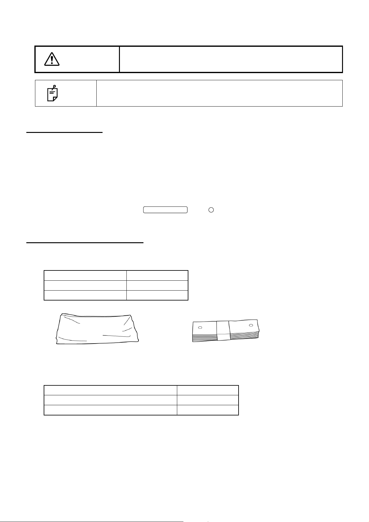
MAINTENANCE
POWER SWITCH
Dust cover
Chinrest tissue
CAUTION
To prevent the instrument from falling and to avoid injury, install the
instrument on a level surface.
NOTE
Do not contact the attachment for anterior segment with rubber products during
storage. The material may deteriorate.
DAILY CHECKUPS
• Dust is a formidable foe to the instrument.
To ensure the production of fine images, care should be taken not to allow fingerprints and/or dirt to
get on the objective lens.
• Each time one patient is changed to another, replace the chinrest paper with new one.
• When not in use, be sure to cap the objective lens and cover the instrument with the dust cover.
• Before using the instrument, check if the objective lens is clean. If the objective lens is stained,
clean it following the instructions for "CLEANING THE OBJECTIVE LENS" on page 93.
• When not in use, always turn the OFF ( ).
ORDERING CONSUMABLES
• When ordering consumables and spare parts, contact your dealer or TOPCON (see the back cover)
and tell them the article name, article code and quantity.
Article name Article code
Chinrest tissue 40310 4082
Dust cover 40496 9011
Xenon Lamp
Article name Article code
Xenon lamp (for Model Model Triton) 40496 6250
Xenon lamp (for Model Model Triton plus) 47012 6250
89
MAINTENANCE
Page 92

REPLACING THE XENON LAMP
To avoid electric shock and burns, do not replace the lamp by yourself.
CAUTION
Ask your dealer for repairs.
90
MAINTENANCE
Page 93
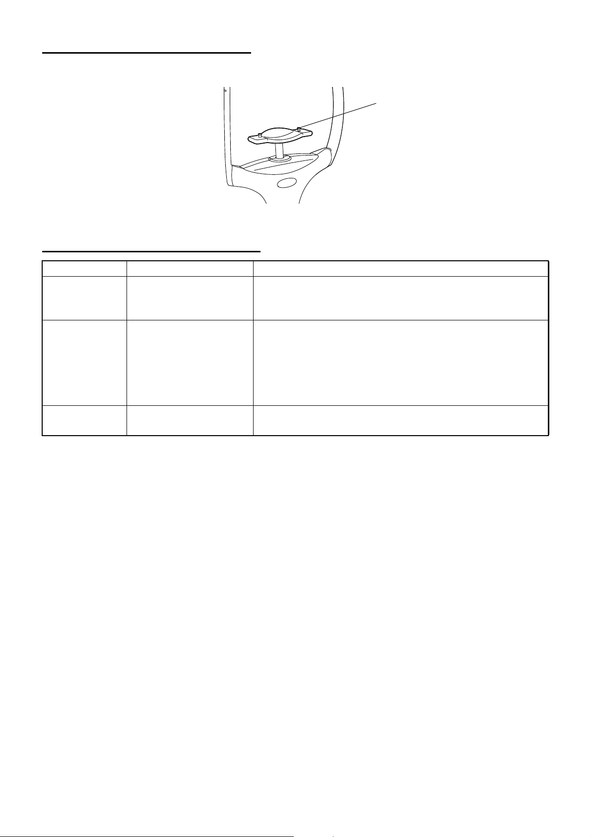
REFILLING THE Chinrest tissue
chinrest tissue pin
• When the Chinrest tissue is used up, pull out the chinrest tissue pin and refill the paper sheet.
MAINTENANCE BY THE DEALER
Item Inspection interval Details
Cleaning each
unit
Checking the
operation
Checking the
light intensity
Within 12 months from
the last maintenance
Within 12 months from
the last maintenance
Within 12 months from
the last maintenance
• Cleaning the external section
• Cleaning the optical system
• Cleaning the base unit
• Anterior segment observation function
• Internal fixation target
• Display on the screen
• Adjusting the observation illumination
• Fundus observation (by test eye)
• Fundus tomography (by test eye)
• Checking the xenon light intensity (by special tool)
• Checking the laser light intensity (by special tool)
91
MAINTENANCE
Page 94
CLEANING
CLEANING THE EXTERNAL COVER, TOUCH DISPLAY AND OTHERS
To avoid damage to the instrument or injury due to an electric shock,
WARNING
• Do not spray liquid on the instrument. The instrument may be damaged or
• Do not spray the cleaner solution directly toward the instrument. If the solu-
NOTE
• When the instrument is not in use, turn off the power switch.
• To prevent the plastic parts of the instrument body from discoloring and deteri-
• Do not apply the lubricating oil such as the machine oil to the sliding board. It
turn off the power switch and remove the power cord before cleaning the
instrument.
those that come into contact with the instrument may be injured by electric
shock.
tion comes into the instrument through a vent or others, the instrument may
malfunction.
orating, do not use volatile solvents for cleaning, such as benzine, thinner,
ether, gasoline, etc.
may be deteriorated to affect the operability adversely.
1 When the external cover and touch display screen become stained, clean them with a dry cloth.
2 If the external cover or the touch display is badly stained, prepare a tepid solution of neutral
detergent. Moisten a cloth and wring it thoroughly. Then, wipe the cover or panel with the cloth.
CLEANING OF THE PARTS WHICH COME INTO CONTACT WITH THE PATIENT
• Before using the instrument, clean the forehead rest unit and chinrest unit.
Mix the neutral detergent in tepid water. Moisten a cloth and wring it thoroughly. Then, wipe the
forehead rest and chinrest with the cloth.
CLEANING THE TOUCH DISPLAY
• The touch display is a touch panel. Before wiping it, turn off the power switch.
If not, the touch display responds to the wiping action to cause a trouble in
NOTE
operation.
• When the monitor cleaner is dirty, wash and use it. Rinse the monitor cleaner
until the cleanser does not remain on it any more. If the cleanser remains on
the monitor cleaner, the touch display is not wiped uniformly from time to time.
92
CLEANING
Page 95

When the touch display is stained by dust or the like
First, remove dust lightly with a soft brush, etc. Then, wipe the screen lightly with the dry monitor
cleaner, which is the accessory.
When the touch display is stained by fingerprint or the like
Wipe the screen lightly with the dry monitor cleaner, which is the accessory.
If the fingerprint is not removed well, moisten the monitor cleaner with water a little and then wipe
the screen with it.
CLEANING THE OBJECTIVE LENS
• To check if the objective lens is stained, darken the room and illuminate the objective lens with a
flashlight, etc. Examine the objective lens diagonally from the front. The lens condition can be seen
clearly.
How to wipe the dustproof coated objective lens
The wiping method is different from the conventional coated lens.
The resistance against wiping is very low and the lens is smooth.
• Dust and dirt adhered to the surface
Blow them off using a blower.
Be careful to prevent the blower end from touching the objective lens.
• When the stain is simple such as dust, tears or saliva:
1 Breathe toward the objective lens and wipe it carefully with a piece of lens cleaning paper.
2 If your lens cleaning paper is dirty, replace it with a clean one and repeat 1.
3 Repeat 1 and 2 until no stain is seen on the lens.
• When the stain is persistent:
1 Moisten a lens cleaning paper with reagent ethanol properly. Wipe the objective lens with the
lens cleaning paper by rubbing lightly.
2 If your lens cleaning paper is dirty, replace it with a clean one and repeat 1.
3 Repeat 1 and 2 until no stain is seen on the lens.
• Don't use the following methods because the lens may be damaged.
• Wiping the lens by grasping with fingernails
• Using a lens cleaning paper wound around a hard tool (for example, a
metallic tool).
NOTE
• Use a soft lens cleaning paper without fiber.
• For example, BEMCOT (Asahikasei)
• Don't let any strong-alkaline liquid adhere to the objective lens.
If such a liquid adheres to the lens, immediately wipe it off.
• If it is difficult to remove a stain from the objective lens, contact your dealer or
TOPCON (see the back cover).
93
CLEANING
Page 96

BEFORE REQUESTING SERVICE
TROUBLESHOOTING
The error messages are displayed with a red or yellow frame on the touch display.
When the error message is displayed, please tell the message ID to service engineers of your dealer
or TOPCON listed on the back cover.
The message ID is displayed in [ ].
Messages during operation
Error message Contents
GALVANO error.
Please turn the power switch OFF.
[010107]
Overcharged Xenon flash.
Please turn the power switch OFF.
[111102]
Internal temperature error.
Please turn the power switch OFF.
[101111/109111/ 110111]
Light volume exceeds upper limit.
Please turn the power switch OFF.
[100112]
Failed to measure internal temperature.
Please turn the power switch OFF.
[109114]
Failed to measure light volume.
Please turn the power switch OFF.
[100115]
Light volume is lower than lower limit.
Please turn the power switch OFF.
[100116]
Internal communication error.
Please turn the power switch OFF.
[209001/210001/211001/212001]
Failed to initialize the built-in image board.
Please turn the power switch OFF.
[201002]
Camera is not connected.
Color fundus photography is disabled.
[202001]
Camera is not connected.
FA/Auto Fluo photography is disabled.
[203001]
Failed to initialize a camera.
Color fundus photography is disabled.
[202002]
Failed to initialize a camera.
FA/Auto Fluo photography is disabled.
[203002]
Failed to charge Xenon flash.
Please turn the power switch OFF.
[211101]
It is probable that the galvano unit does not operate properly.
Turn off the power and contact the service engineer.
Overcharge has occurred in the xenon lamp (fundus photography light source) power supply.
Turn off the power and contact the service engineer.
The temperature in the instrument is abnormally high.
Turn off the power and contact the service engineer.
The laser light intensity is beyond the upper limit value.
Turn off the power and contact the service engineer.
An error in the communication with the temperature sensor
has occurred.
Turn off the power and contact the service engineer.
Measuring the laser light intensity has failed.
Turn off the power and contact the service engineer.
The laser light intensity is below the lower limit value.
Turn off the power and contact the service engineer.
An error in the communication between the built-in PCBs
has occurred.
Turn off the power and contact the service engineer.
Initialization of the image board has failed.
Turn off the power and contact the service engineer.
The connection with the color photography camera has
failed. Turn off the power and contact the service engineer.
The connection with the FA/FAF photography camera has
failed. Turn off the power and contact the service engineer.
An initialization error of the color photography camera has
occurred.
Turn off the power and contact the service engineer.
An initialization error of the FA/FAF photography camera
has occurred.
Turn off the power and contact the service engineer.
An error has occurred while the xenon lamp (fundus photography light source) power supply is being charged.
Turn off the power and contact the service engineer.
94
BEFORE REQUESTING SERVICE
Page 97

Error message Contents
FPGA initialization error.
Please turn the power switch OFF.
[210108]
Lamp house cover is off.
Please turn the power switch OFF and close the
cover.
[209109]
FAN error.
Please turn the power switch OFF.
[209110/211110]
Failed to detect the center position of Ystage.
Please reboot.
[311202]
EEPROM data error.
Please reboot.
[309204/310204]
TRC focus motor initialization error.
Please reboot.
[309205]
Split unit motor initialization error.
Please reboot.
[309206]
Diopter scale lens initialization error.
Please reboot.
[309207]
Small pupil diaphragm motor initialization error.
Please reboot.
[309208]
Split initialization error.
Please reboot.
[309209]
OCT focus motor initialization error.
Please reboot.
[310210]
Optical path correction motor initialization error.
Please reboot.
[310211]
Polarizer motor initialization error.
Please reboot.
[310212]
Optical path switching motor initialization error.
Please reboot.
[312214]
Initialization of the built-in FPGA has failed.
Turn off the power and contact the service engineer.
It is probable that the lamp house cover comes off or is not
attached properly.
Turn off the power and contact the service engineer.
The FAN rotary speed is not normal. The temperature in the
instrument may be higher.
Turn off the power and contact the service engineer.
An error has occurred while the Y stage is initially operating.
Restart the instrument. Contact the service engineer for
inspection.
The EEPROM data in the built-in PCB is not normal.
Restart the instrument. Contact the service engineer for
inspection.
An error has occurred while the TRC focus motor is initially
operating.
Restart the instrument. Contact the service engineer for
inspection.
An error has occurred while the split unit is initially operating.
Restart the instrument. Contact the service engineer for
inspection.
An error has occurred while the diopter compensation lens
motor is initially operating.
Restart the instrument. Contact the service engineer for
inspection.
An error has occurred while the small pupil diaphragm motor
is initially operating.
Restart the instrument. Contact the service engineer for
inspection.
An error has occurred while the split motor is initially operating.
Restart the instrument. Contact the service engineer for
inspection.
An error has occurred while the OCT focus motor is initially
operating.
Restart the instrument. Contact the service engineer for
inspection.
An error has occurred while the light path length compensation motor is initially operating.
Restart the instrument. Contact the service engineer for
inspection.
An error has occurred while the polarization controller motor
is initially operating.
Restart the instrument. Contact the service engineer for
inspection.
An error has occurred while the light path switching motor is
initially operating.
Restart the instrument. Contact the service engineer for
inspection.
95
BEFORE REQUESTING SERVICE
Page 98

Error message Contents
Barrier filter motor initialization error.
Please reboot.
[312215]
Failed to detect the center position of exciter filter.
Please reboot.
[312216]
Iris diaphragm initialization error.
Please reboot.
[312217]
Failed to start imaging.
Please reboot.
[301401]
Out of memory.
Please turn the power switch OFF and try again.
[300402]
Failed to start sending image.
Please reboot.
[301403]
Failed to write the data.
Please set again.
[300403/300408]
Internal battery may have run out.
Please set date and time.
[300404]
Communication error is occurred.
Check the connection to the external PC.
[300405]
The state of the external PC software is abnormal.
Please redo the operation from the beginning.
[300406]
You may not get high-sensitive OCT image. Proceed?
[300407]
Anterior Segment Calibration file doesn't exist.
You cannot select the anterior segment capture
mode.
[300409]
Failed to load baseline-data.
[300418]
Failed to capture the data.
[300419]
Failed to receive data from the external PC.
Please redo the operation from the beginning.
[300420]
An error has occurred while the barrier filter motor is initially
operating.
Restart the instrument. Contact the service engineer for
inspection.
An error has occurred while the exciter filter motor is initially
operating.
Restart the instrument. Contact the service engineer for
inspection.
An error has occurred while the iris aperture motor is initially
operating.
Restart the instrument. Contact the service engineer for
inspection.
Start to store the image into the image board has failed.
Restart the instrument. Contact the service engineer for
inspection.
It is not possible to continue the processing because of the
insufficient memory capacity. Turn off the power and contact the service engineer.
Start to transfer the image from the image board has failed.
Restart the instrument. Contact the service engineer for
inspection.
An error has occurred while data is being written to the builtin PCB.
Perform setting again. If the problem is not solved, contact
the service engineer.
It is probable that the built-in battery is dead. The setting of
date/time has been cleared. Set date/time. Ask the service
engineer to replace the battery.
An error in the communication between the instrument and
the external personal computer has occurred. Check
whether the LAN cable is properly connected to the instrument and the external personal computer.
If the problem is not solved, contact the service engineer.
A mismatch in the communication between the instrument
and the external personal computer has occurred.
Perform the operation from the beginning again. If the problem is not solved, contact the service engineer.
The laser light intensity is lowered.
The tomogram sensitivity may be lowered. Contact the service engineer for inspection.
Reading the anterior segment calibration file has failed.
Contact the service engineer for inspection.
Reading the baseline data by the external personal computer has failed.
Contact the service engineer for inspection.
Taking a picture has failed.
Contact the service engineer for inspection.
Data cannot be received from the external personal computer.
Perform the operation from the beginning again. If the problem is not solved, contact the service engineer.
96
BEFORE REQUESTING SERVICE
Page 99

Error message Contents
Failed to change configuration of the built-in image
board.
Please reboot.
[301402]
Failed to stop sending image.
[301404]
Failed to send data.
[301405]
Failed to read data from the buiti-in image board.
[301406]
Failed to get buffer of the buiti-in image board.
[301407]
Failed to receive data from the external PC.
[301408]
Failed to register baseline data.
[301409]
Failed to start tracking operation.
[301410]
Camera configuration will change.
Please reboot.
[302401/303401]
Failed to capture image.
[309401]
Capturing cannot start without the anterior segment lens unit.
[400410]
Capturing cannot start attaching the anterior segment lens unit.
[400411]
Changing the image board setting has failed.
Restart the instrument. Contact the service engineer for
inspection.
Stopping to transfer the image has failed.
Contact the service engineer for inspection.
Transferring the data has failed.
Contact the service engineer for inspection.
Reading the data from the image board has failed.
Contact the service engineer for inspection.
Obtaining the buffer of the image board has failed.
Contact the service engineer for inspection.
Receiving the data from the personal computer has failed.
Contact the service engineer for inspection.
Registering the baseline data has failed.
Contact the service engineer for inspection.
Starting the tracking operation has failed.
Contac the service engineer for inspection.
The camera setting will be changed.
Restart the instrument. Contact the service engineer for
inspection.
Capturing the image has failed.
Contact the service engineer for inspection.
The anterior segment lens unit is not installed. The anterior
segment lens unit is necessary for the anterior segment
OCT photography. Check whether the anterior segment
lens unit is installed.
The anterior segment lens unit is installed. The anterior
segment lens unit is not necessary for others except the
anterior segment OCT photography. Remove it.
The following messages are displayed with a white frame on the touch display.
When the error message is displayed, check the operation according to the message's contents.
Messages during operation
Error message Contents
Detected blink while capturing fundus image.
Please try again.
[509402]
Could not detect image. Please push [Optimize]
button to try again.
[500414]
The data might have been captured on the unexpected position because of the eye movement.
[500415]
Failed in tracking. Do you want to retry?
[500416]
Failed in Follow-up capture. It will retry.
[500417]
Blink is detected during photography.
Check whether the patient's eye is properly opened and
then take a picture again.
Optimizing the tomogram has failed.
Check the tomogram and then perform optimizing again.
It is probable that the 3D scan was not performed correctly.
Check the photography data and take a picture again if necessary.
Tracking has failed during photography.
Check the fundus image and then take a picture again.
Tracking has failed during Follow-up photography.
Check the fundus image and then take a picture again.
97
BEFORE REQUESTING SERVICE
Page 100

Error message Contents
Please attach the anterior segment lens unit. The anterior segment lens unit is not installed. The anterior
segment at tachment kit is necessary for the anterior segment OCT photography. Check whether the anterior segment attachment kit is installed.
Please detach anterior segment lens unit. The anterior segment lens unit is installed. The anterior
segment attachment kit is not necessary for others except
the anterior segment OCT photography. Remove it.
The operation is canceled for the external PC software processing.
The entered value is out of range. For the settable range, check the details of the setting
The operation is canceled because the external personal
computer software processing is in progress.
Take a picture again.
menu.
98
BEFORE REQUESTING SERVICE
 Loading...