

Page 1

http://www.topcon.co.jp
Please see the attached address list or the following website for contact addresses.
GLOBAL GATEWAY http://global.topcon.com/
INSTRUCTION MANUAL
DIGITAL LEVEL
DL-500 SERIES
DL-502
DL-503
FC11808-A022-02
Page 2

SURVEYING INSTRUMENTS
DIGITAL LEVEL
DL-502
DL-503
DL-500 SERIES
INSTRUCTION MANUAL
Thank you for selecting the Digital Level DL-502/503.
• Please read this operator's manual carefully before using this
product.
• Verify that all equipment is included. See "20.1 Standard Equipment".
• DL-502/503 has a function to output data saved in DL-502/503 to
a connected computer. Commands operations from a computer
can also be performed. For details, refer to the “Output Formats
and Command Explanations (DL Edition)” manual and ask your
local dealer.
• The specifications and general appearance of the instrument are
subject to change without prior notice and without obligation by
TOPCON Corporation and may differ from those appearing in this
manual.
• The content of this manual is subject to change without notice.
• Some of the diagrams in this manual may be simplified for easier
understanding.
1
Page 3

CONTENTS
Read This First
Introduction
Preliminaries
Surveying
Managing
Recorded Data
1. Precautions for Safe Operation ..........................4
2. Precautions.........................................................7
3. DL Functions ......................................................9
3.1 Parts of the Instrument and Operation .......9
3.2 Display......................................................11
3.3 Operating Keys.........................................15
3.4 Operating Modes ......................................16
4. Installing and Removing the Battery.................18
5. Setting Up the Instrument.................................19
6. Focusing and Sighting ......................................20
7. Basic Operation ................................................22
7.1 Reading the Staff......................................22
7.2 Measuring in Status Mode........................25
7.3 Measuring using Wave-and-Read ............26
8. Setting Up Data Storage...................................29
8.1 JOB Setting ..............................................29
8.2 Record Conditions ....................................31
8.3 Double-run Measurement.........................32
8.4 Flow of Recording Data ............................32
9. Measuring Height Difference ............................36
10. Measuring Elevation .........................................39
11. Setting Out Height Difference, Distance, and
Elevation...........................................................42
11.1 Setting Out Height Difference...................42
11.2 Setting Out Distance.................................44
11.3 Setting Out Elevation................................45
12. Other Measurement Functions .........................48
12.1 Measuring Horizontal Angle .....................48
12.2 Using the Instrument as a Standard
Level .........................................................48
13. Displaying Recorded Data ................................49
13.1 Data Check and Edit.................................49
2
Page 4

Managing
Recorded Data
Other
Procedures
Specifications
Regulations
13.2Number of Recorded Points............................50
14. JOB Delete .......................................................51
15. Sending Recorded Data ...................................53
15.1 Connecting to a Computer or Data
Collector ...................................................53
15.2 Data Output ..............................................54
16. Changing the Settings ......................................56
16.1 Measuring Mode.......................................56
16.2 Fractional / Decimal representation of
Height Unit................................................57
16.3 Communication Parameters .....................58
16.4 Auto Power-Off .........................................58
16.5 Unit of Measurement ................................59
17. Warnings and Error Messages .........................60
18. Charging the Battery.........................................63
19. Checks and Adjustments..................................65
19.1 Adjusting the Circular Level......................65
19.2 Adjusting the Reticle.................................66
20. Equipment and Accessories .............................72
20.1 Standard Equipment.................................72
20.2 Optional Accessory...................................73
20.3 Staffs ........................................................74
21. Specifications ...................................................76
22. Regulations.......................................................80
3
Page 5
1. Precautions for Safe Operation
For the safe use of the product and prevention of injury to operators
and other persons as well as prevention of property damage, items
which should be observed are indicated in this operator's manual by
WARNING and CAUTION indications.
The definitions of the indications are listed below. Be sure you
understand them before reading the manual's main text.
Definitions of Indications
Read This First
Ignoring this indication and making an operation
WARNING
CAUTION
General
Warning
• Do not use voltage other than the specified power supply voltage.
Fire or electrical shock could result.
• Do not use the unit in areas exposed to high amounts of dust or
ash, in areas where there is inadequate ventilation, or near
combustible materials. An explosion could occur.
• Do not perform disassembly or rebuilding. Fire, electric shock or
burns could result.
• Never look at the sun through the telescope. Loss of eyesight could
result.
• Do not look at reflected sunlight from a prism or other reflecting
object through the telescope. Loss of eyesight could result.
Caution
• Do not use the carrying case as a footstool. The case is slippery
and unstable so a person could slip and fall off it.
• Do not place the instrument in a case with a damaged catch, belt or
handle. The case or instrument could be dropped and cause injury.
error could possibly result in death or serious
injury to the operator.
Ignoring this indication and making an operation
error could possibly result in minor injury or
property damage.
4
Page 6

Staff
Warning
• Do not use under thunderous weather conditions. This unit is
conductive and if struck by lightning, death or injury could result.
• Handle with care when using near high voltage cables or
transformers. This unit is conductive and contact could result in
electric shock.
Tripod
Caution
• When mounting the instrument to the tripod, tighten the centering
screw securely. Failure to tighten the screw properly could result in
the instrument falling off the tripod, causing injury.
• Tighten securely the leg fixing screws of the tripod on which the
instrument is mounted. Failure to tighten the screws could result in
the tripod collapsing, causing injury.
• Do not carry the tripod with the tripod shoes pointed at other
persons. A person could be injured if struck by the tripod shoes.
• Keep hands and feet away from the tripod shoes when fixing the
tripod in the ground. A hand or foot stab wound could result.
• Tighten the leg fixing screws securely before carrying the tripod.
Failure to tighten the screws could lead to the tripod legs extending,
causing injury.
Power Supply
Warning
• Use only the specified battery charger to recharge batteries. Other
chargers may be of different voltage rating or polarity, causing
sparking which could lead to fire or burns.
• Do not place articles such as clothing on the battery charger while
charging batteries. Sparks could be induced, leading to fire.
• Do not use damaged power cords, plugs or loose outlets. Fire or
electric shock could result.
• Do not use batteries or the battery charger if wet. Resultant
shorting could lead to fire or burns.
Read This First
5
Page 7

• To prevent shorting of the battery in storage, apply insulating tape
or equivalent to the terminals. Otherwise shorting could occur
resulting in fire or burns.
• Do not heat or throw batteries into fire. An explosion could occur,
resulting in injury.
• Do not connect or disconnect power supply plugs with wet hands.
Electric shock could result.
Caution
• Do not touch liquid leaking from batteries. Harmful chemicals could
Read This First
cause burns or blisters
6
Page 8

2. Precautions
Using the Instrument
• The DL-502/503 is a precision instrument. Avoid severe shocks or
vibration.
• Be careful when removing the instrument from its case.
• Do not place the DL-502/503 directly on the ground.
• When the operator leaves the DL-502/503, the vinyl cover should
be placed on the instrument.
• Never carry the DL-502/503 on the tripod to another site.
• Always turn the instrument off and remove the battery before
storing the instrument in its case.
• When the instrument is placed in the carrying case, see "20.1
Standard Equipment".
• Always wipe off moisture and dirt adhering to the instrument during
survey work. Moisture or dirt on the lens may result in incorrect
readings.
• Consult your local dealer before using the instrument under special
conditions such as long periods of continuous use or high levels of
humidity. In general, special conditions are treated as being outside
the scope of the product warranty.
Maintenance
• Always clean the instrument before returning it to the case. The
lens requires special care. Dust it off with the lens brush first, to
remove tiny particles. Then, after providing a little condensation by
breathing on the lens, wipe it with the supplied cleaning cloth or
lens tissue.
• If the display is dirty, carefully wipe it with a soft, dry cloth. To clean
other parts of the instrument or the carrying case, lightly moisten a
a soft cloth in a mild detergent solution. Wring out excess water
until the cloth is slightly damp, then carefully wipe the surface of the
unit. Do not use any organic solvents or alkaline cleaning solutions.
• Store the instrument and accessories in a dry room where the
temperature remains fairly constant.
• If any trouble is found with the screws or optical parts (e.g. lens),
contact your local dealer.
Read This First
7
Page 9

• Always close the case when empty to protect the interior from
humidity and dust.
• Regular checking and adjustment is recommended to maintain
instrument precision.
Exceptions from responsibility
• The user of this product is expected to follow all operating
instructions and make periodic checks (hardware only) of the
product’s performance.
• The manufacturer, or its representatives, assumes no responsibility
Read This First
for results of faulty or intentional usage or misuse including any
direct, indirect, consequential damage, or loss of profits.
• The manufacturer, or its representatives, assumes no responsibility
for consequential damage, or loss of profits due to any natural
disaster, (earthquake, storms, floods etc.), fire, accident, or an act
of a third party and/or usage under unusual conditions.
• The manufacturer, or its representatives, assumes no responsibility
for any damage (change of data, loss of data, loss of profits, an
interruption of business etc.) caused by use of the product or an
unusable product.
• The manufacturer, or its representatives, assumes no responsibility
for any damage, and loss of profits caused by usage different to
that explained in the operator’s manual.
• The manufacturer, or its representatives, assumes no responsibility
for damage caused by incorrect operation, or action resulting from
connecting to other products.
8
Page 10
3. DL Functions
• Except where stated, screens and illustrations appearing in this
manual are of DL-502/503.
• In principle, screens used in procedures are based on the factory
setting.
Important:
1
2
3
4
5
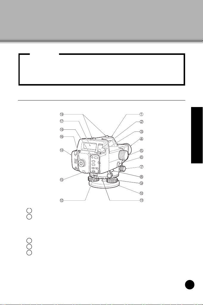
3.1 Parts of the Instrument and Operation
Introduction
Handle
Bubble mirror
When the instrument is placed high up and cannot be viewed
from above, you can use the mirror to check the position of the
bubble in the tube.
Circular level
Objective lens
Focusing knob
Use this knob to focus on the staff.
9
Page 11

Introduction
6
Measure
7
8
9101112131415
161718
Measure key (appears as in this manual)
Starts measurement.
(See "3.3 Operating Keys".)
Horizontal fine motion knobs (both sides)
Use these knobs to finely adjust the instrument's horizontal
position.
Data output connector
You can connect a data collector or computer to this connector.
Leveling foot screw
Base plate
Horizontal circle positioning ring
You can rotate the horizontal scale while the instrument is fixed
in position. Use to align benchmarks with '0', etc.
Horizontal circle
Reticle adjusting screw and screw cover
Use this screw to mechanically adjust the reticle.
Battery cover
Eyepiece
Adjust the reticle focus to suit your eyesight.
Keyboard (See "3.3 Operating Keys".)
Display (See "3.2 Display".)
Gunsight
Use for coarse adjustment of the orientation of the instrument.
10
Page 12
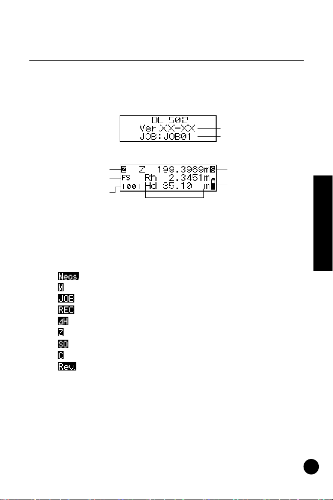
3.2 Display
Version number
Currently selected
JOB
Measurement
Battery level
conditions
indicator
Mode indicator
Attribute•Measure-
Point number
ment step
Measurement values and other data
The display includes the following marks which indicate the
operating status and current mode, and help the operator to
keep track of the measurement procedure.
• Point number display
The next point number to be recorded is displayed.
• Mode display
The displayed mark shows the current mode.
: Status mode or Measurement mode
: Menu mode
: JOB setting mode
: Record setting mode
: Height difference measurement mode
: Elevation measurement mode
: Setting out mode
: Configuration mode
: Data review menu
Introduction
11
Page 13

• Attribute•Measurement step display
Displays the backsight and foresight (in Height difference, Setting
out, or Measuring elevation modes).
: Backsight
: Foresight
Displays the attribute of the recorded measurement value (Height
difference measurement mode, Elevation measurement mode).
: Backsight point
: Foresight point
: Intermediate sight
: Fixed point
:Off
Displays the measurement step (when Adjustment is selected in
the Configuration mode).
At position A
: Take a reading on staff a.
: Take a reading on staff b.
Introduction
: Take a reading on staff a with the tripod turned 180°.
: Take a reading on staff b with the tripod turned 180°.
At position B
: Take a reading on staff a.
: Take a reading on staff b.
: Take a reading on staff a with the tripod turned 180°.
: Take a reading on staff b with the tripod turned 180°.
Displays the page number of the active menu (when the Menu
mode or Configuration mode is selected).
:First page
: Second page
• Measuring mode (not displayed on menu screens)
Displays the currently selected measuring mode.
: Single measurement
: Average measurement
: Wave-and-Read measurement
: Repeat measurement
: Tracking measurement
12
Page 14
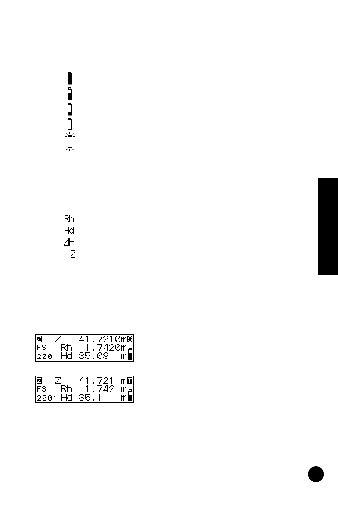
• Battery level (not displayed on menu screens)
Displays the current power level of the battery.
: Level 3: Full power.
: Level 2: Plenty of power remains.
: Level 1: Half or less power remains.
: Level 0: Little power remains. Charge the battery.
: Low: No power remains (A beep tone sounds and the
battery symbol blinks.) Charge the battery. Operation
cannot be performed. After a short time the instrument
automatically powers off.
• Measurements
The following symbols are displayed.
: Staff reading (height)
: Horizontal distance to staff
: Height difference
:Elevation
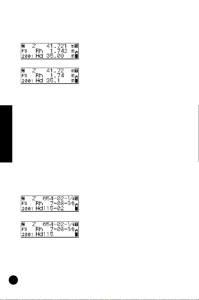
The fractional/decimal display format for measurement value,
calculation value and input value depends on the settings in
measuring mode and fractional/decimal representation of height
units. (See "16. Changing the Settings".)
• When the fractional/decimal display format is set to "0.0001m" and
the unit of measurement is "m", the display is as follows:
When measuring mode is "Single",
"Average" or "Repeat"
Height: Up to 4 decimals
Distance: Up to 2 decimals
When measuring mode is "Tracking"
Height: Up to 3 decimals
Distance: Up to 1 decimal
Introduction
13
Page 15
• When the fractional/decimal display format is set to "0.001m" and
the unit of measurement is "m", the display is as follows:
When measuring mode is "Single",
"Average" or "Repeat"
Height: Up to 3 decimals
Distance: Up to 2 decimals
When measuring mode is "Tracking"
Height: Up to 2 decimals
Distance: Up to 1 decimal
• When the fractional/decimal display format is set to "0.001ft" and
the unit of measurement is "ft", data is displayed as follows:
When measuring mode is "Single", "Average" or "Repeat"
Height: Up to 3 decimals
Distance: Up to 1 decimal
When measuring mode is "Tracking"
Height: Up to 2 decimals
Distance: 0 decimal
• When the fractional/decimal display format is set to "0.01ft" and the
unit of measurement is "ft", data is displayed as follows:
Introduction
When measuring mode is "Single", "Average" or "Repeat"
Height: Up to 2 decimals
Distance: Up to 1 decimal
When measuring mode is "Tracking"
Height: Up to 1 decimal
Distance: 0 decimal
• When the fractional/decimal display format is set to "1/8" and the
unit of measurement is "inch", the display is as follows:
When measuring mode is "Single",
"Average" or "Repeat"
Height: **-**-*/
*
Distance: **-**
When measuring mode is "Tracking"
Height: **-**-*/
*
Distance: **
14
Page 16
3.3 Operating Keys
• The fractional/decimal display format for distance measurements
depends on the setting in measuring mode only.
Note:
Measure
Measure
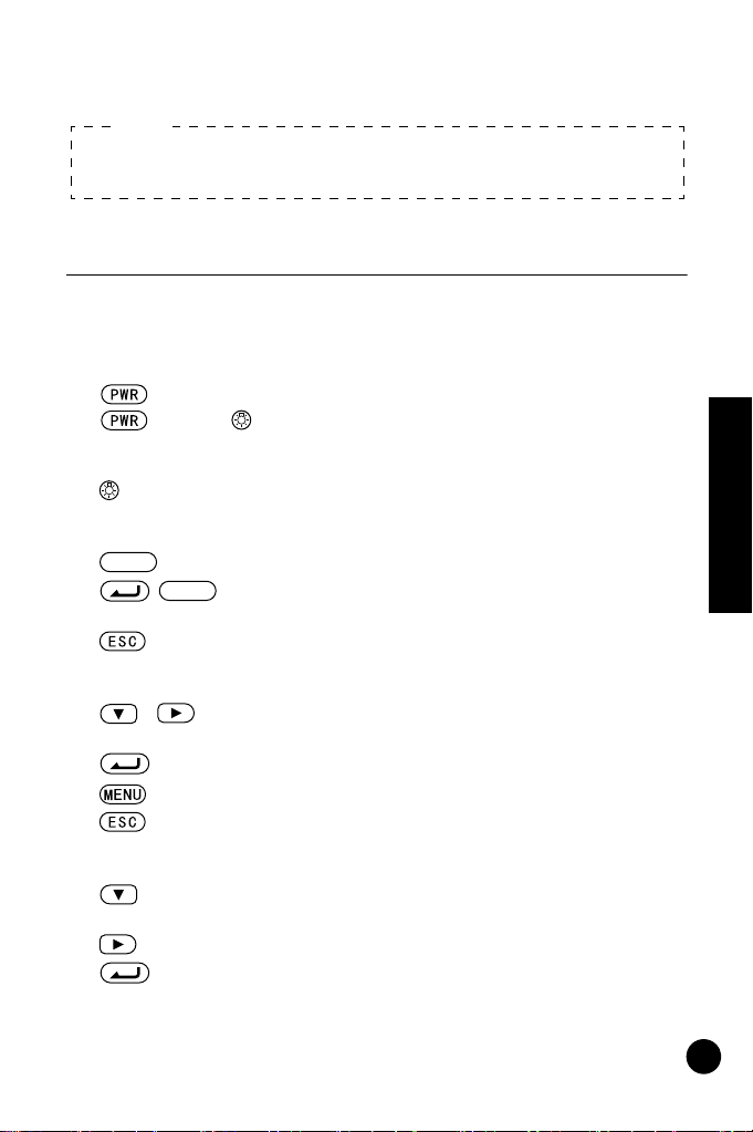
Learn main key operations here.
• Power ON/OFF
: Power the instrument ON
(hold) + : Power the instrument OFF
• Light up the display
: Switch the display backlight ON / OFF
• Measurement start / stop
: Start measurement
/ : Stop measurement (in repeat, average or tracking
mode)
: Cancel measurement
• Select / cancel (return to former procedure) menus and options
/ : Scroll to next position (JOB selection, item selection,
etc.)
: Accept the option
: Enter Menu mode
: Return to former procedure or to Status mode
• Value input / cancel
: Advance the numeral
Toggle the +/- sign
: Change the position of the inverted cursor
: Accept the input value
Introduction
15
Page 17
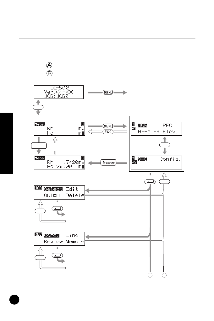
3.4 Operating Modes
The DL has a number of functional modes. This section
shows the screens that can be displayed in each mode.
: Key operation for selecting each menu
: Key operation for returning to previous screen
[Instrument information mode]
ESC
[Status mode]
[Screen showing the number
of points that can be
recorded is displayed]
[Menu mode]
(Page 1)
Introduction
16
[At completion of a
Measure
measurement]
[Measurement mode]
[Job setting mode]
Select
ESC
[Record setting mode]
ESC
[Menu of selected
function is displayed]
Select
[Menu of selected
function is displayed]
(Page 2)
Select
A B
MENU
ESC
Page 18

[Height difference measurement mode]
ESC
Select
[Menu of selected
function is displayed]
Select
[Menu of selected
function is displayed]
[Elevation measurement mode]
[Setting out .....]
[Config. mode]
(Page 1)
(Page 2)
MENU
A B
Introduction
17
Page 19
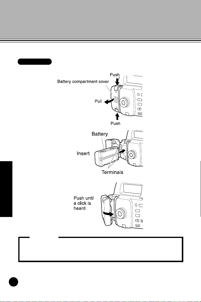
4. Installing and Removing the Battery
Procedure
• Always turn off the power before removing the battery from the
instrument. If the battery is removed when the power is still on,
stored data may be lost.
Important:
Install a fully-charged battery (see "18. Charging the Battery").
1
2
3
Preliminaries
18
Page 20

5. Setting Up the Instrument
Procedure
1 Set up the tripod.
Spread the tripod legs about the same distance apart so that the
tripod head is approximately level. Tread the tripod shoes firmly into
the ground.
2 Mount the instrument on the tripod.
Hold the instrument on the tripod head and tighten the centering
screw.
3 Level the instrument.
Spherical head tripod: Loosen the centering screw and slide the
instrument across the tripod head until the
bubble is centered in the circular level.
Tighten the centering screw.
Flat head tripod: Extend or push in the tripod legs until the
bubble is centered in the circular level.
When the bubble is more or less centered,
turn the leveling foot screws until the
bubble is exactly centered in the circle.
When you turn a screw clockwise, raising
the instrument, the bubble will move toward
the position of that screw.
Preliminaries
19
Page 21

6. Focusing and Sighting
Procedure
• If deviation occurs at step 5, errors will occur when taking
measurements. Always make sure the instrument is correctly
focused.
Important:
• Before using the instrument
Turn the eyepiece to adjust the eyepiece image.
1 Using the gunsight, aim the objective lens toward the staff.
2 Gradually turn the eyepiece outward, stopping just before the
reticle cross-lines become blurred.
3 Turn the horizontal fine motion knobs until the staff is nearly
centered in the field of view, then turn the focusing knob to focus on
the staff.
4 Looking through the telescope, shift your eyes slightly up and down
and to each side.
Preliminaries
5 If the staff and reticle show no deviation, the instrument is ready for
use.
If the staff and reticle deviate, return to step 2.
20
Page 22
• Focusing when taking measurements
Procedure
• If the staff barcodes are out of focus, they will not be readable
and measurements cannot be taken. Make sure they are
correctly focused.
Important:
1 Using the gunsight, aim the objective lens toward the staff.
2 Turn the horizontal fine motion knobs until the staff is nearly
centered in the field of view, then turn the focusing knob to focus on
the staff.
Preliminaries
21
Page 23

7. Basic Operation
• Set up the staff in an area free of obstacles.
Avoid placing the staff next to mirror-like surfaces. The effect of
strong light could make measurement impossible.
• Support the staff so that it is perpendicular, checking the circular
bubble scope on the staff. If the staff is tilting, height and distance
measurements will be incorrect.
• If the surface is catching the light, turn it just enough to stop the
reflection.
• Make sure shadows are not cast on the staff as this could make
measurement impossible.
• When holding the staff during measurement, make sure your
hand does not cover the RAB code.
• If dark locations make measurement difficult, shine a flashlight on
the staff. Stand at a distance so that the beam shines evenly
over the length of the staff.
Important:
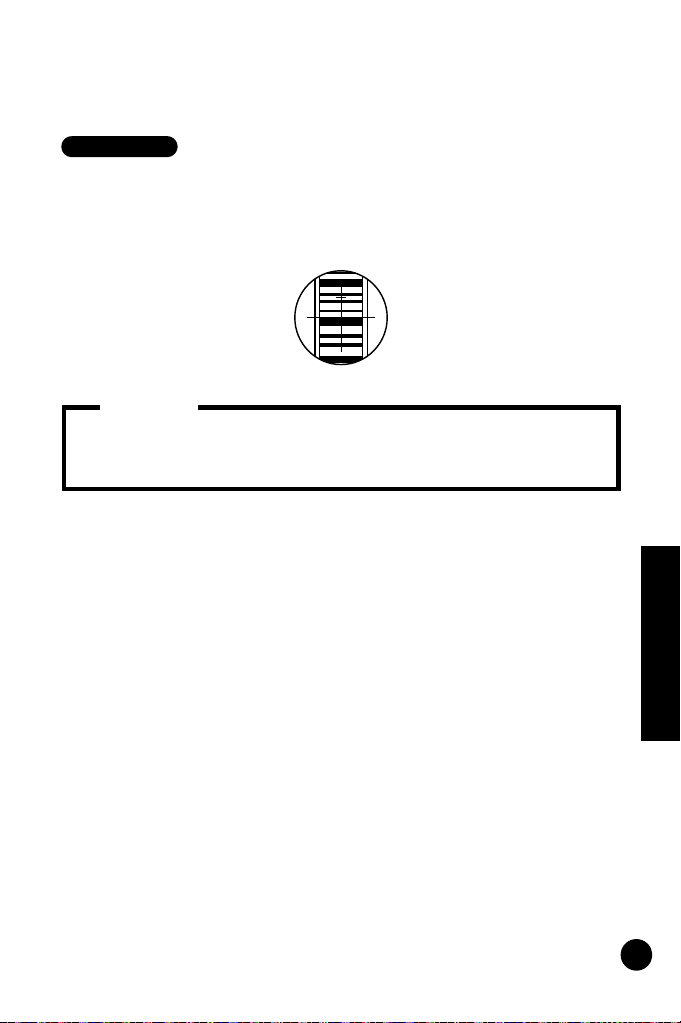
7.1 Reading the Staff
Simply focus on the RAB* code for an automatic reading of
the staff. The following explains how to read the RAB code
of the staff.
* : RAB code (Random Bi-directional code) is a coded staff
used with DL-500 line of digital levels.
Surveying
22
(Continued on next page)
Page 24

(Continued from previous page)
• If waterdrops or dirt adhere to the barcode, measurement may be
impossible. Wipe the staff clean with a soft cloth.
• Clean the staff if grit or dirt gets stuck between the sections. If the
staff is dirty, measurements will not be very accurate.
• Avoid scratching or soiling the barcode surface as this could
make measurement impossible. Store and carry the staff inside
its case.
• If the BGS series staff is used for leveling, and the height
difference and temperature difference are much larger than
normal, temperature variations may cause the staff to expand or
contract and cause differences in relative height measurements.
DL-502/503 reads in measurements up to 0.1mm and minor
deviations in the accuracy of the staff will adversely affect
accuracy. To obtain high accuracy measurements, it is important
to perform temperature corrections for the staff. (See the Note
below for details.)
Procedure
• Setting up the staff
1 Connect the staffs correctly by making sure the numbers on the
numeric scale side of the staffs run in unbroken order.
2 Set the foot plate on the ground so that the staff will not sink.
3 Keeping an eye on the circular bubble scope on the staff, set the
staff in the foot plate so that it stands up straight.
4 Turn the barcode scale toward the instrument.
Surveying
23
Page 25
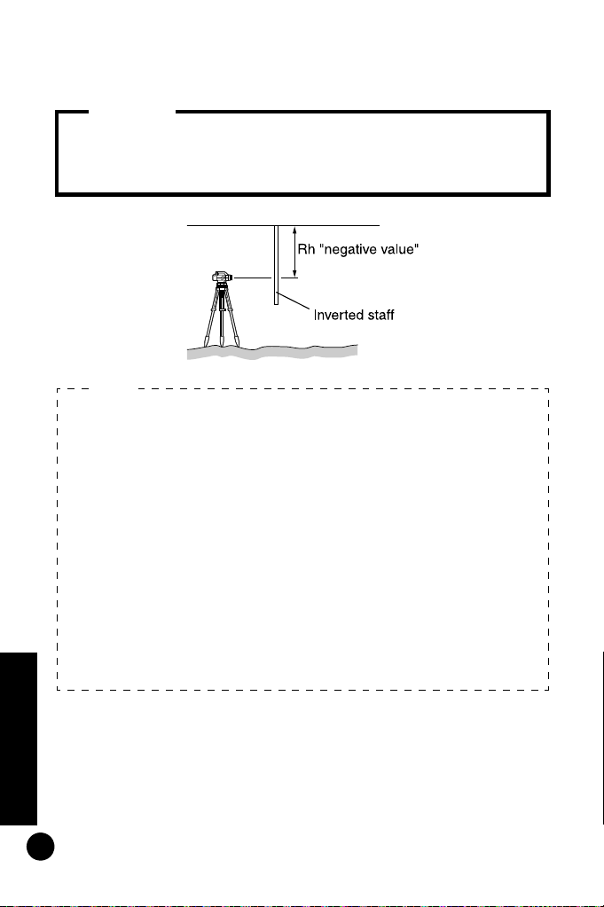
• Measuring the height from a ceiling
• Not possible with Wave-and-Read function. Attempting such
measurement with the Wave-and-Read function will result in an
error.
Important:
Formula for correcting expansion and contraction of the
staff due to temperature changes
C={C0+(T-T0)x }x h
C: Staff correction value
C0: Scale factor
T: Measured temperature during observation (average
temperature during measurement of known site,
intermediate site, new site)
T
0: Reference temperature of 20 C
: Line expansion coefficient
(BGS series : 20x10
-6
1/ C)
h: Height difference
ΔαΔΔ°α°
Δ
Note:
Surveying
24
Page 26
7.2 Measuring in Status Mode
• During measurement, if direct sunlight or strong light enters the
eyepiece and measurement cannot be performed,
"Measurement error" or "Too bright" is displayed (see "17.
Warnings and Error Messages"). Shield the eyepiece from the
light source using your body or cover the eyepiece with your
hand and resume measurement.
• If the DL-502/503 is subjected to shocks or vibration during use,
measurement may be impossible. Resume measurement during
more stable conditions.
Important:
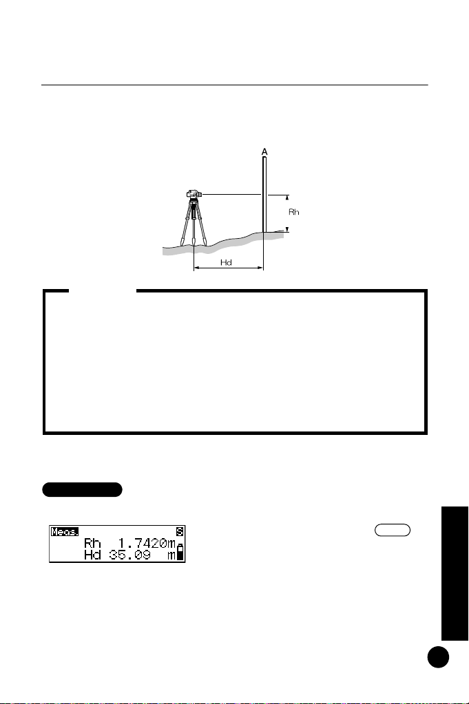
Procedure
Measure
In status mode you can sight point A, take the staff reading
(Rh), and measure the horizontal distance (Hd) to the staff.
The procedure below is for taking single measurements. For
repeat measurements, see the notes.
1 Turn the power switch on.
2 Focus on the staff and press .
Operation starts and the display blinks
while measurements are being taken.
When measurement is completed,
the staff readings (Rh) and horizontal
distance (Hd) are displayed.
Surveying
25
Page 27

7.3 Measuring using Wave-and-Read
• In Repeat, Average, or Tracking mode:
Step 2: Values are renewed at each measurement.
Press or to stop the reading.
Press to cancel the reading.
Measure
Note:
Wave staff
back and forth
The Wave-and-Read function reduces measurement error due to the
staff not being vertical (i.e. tilting). It also allows measurement using a
staff not equipped with a bubble scope.
Wave-and-Read can be used to take the staff reading (Rh), and
measure the horizontal distance (Hd) to the staff.
Surveying
26
Page 28

The forward and backward movement with respect to vertical position
Vertical
OK
No good No good
Procedure
A should be equal and not in excess of 5 to 10°.
1 Turn the power switch on.
2 Set measuring mode to “Waving”.
(see "16.1 Measuring Mode")
3 Focus on the staff.
4 Wave the staff backwards and
forwards (5 to 10°) through the
vertical position. Waving speed
should be equivalent to 3 passings of
the staff through the vertical position
in approximately 3 seconds.
Surveying
27
Page 29

5 Press to start measurement.
Measure
• During measurement, if direct sunlight or strong light enters the
eyepiece and measurement cannot be performed,
"Measurement error" or "Too bright" is displayed (see "17.
Warnings and Error Messages"). Shield the eyepiece from the
light source using your body or cover the eyepiece with your
hand and resume measurement. Conversely, measurement
cannot be performed when light conditions are too dark.
• Measurement cannot be performed when the staff is waved too
fast.
• Measurement cannot be performed when the staff is waved from
side to side (left to right). "Measurement error" is displayed (see
"17. Warnings and Error Messages").
Important:
A beep tone sounds and the display
blinks. Consecutive arrows are
displayed to indicate the progress of
measurement.
When measurement is completed, a
beep tone sounds twice and the staff
readings (Rh) and horizontal distance
(Hd) are displayed.
Surveying
28
Page 30

8. Setting Up Data Storage
• *: Factory setting
• Settings are saved even after the instrument is turned off.
• Up to 2000 points can be registered. If 2000 points have already
been recorded, a beep tone sounds twice and the number of
free points remaining is displayed as "0". Measurement results
are not recorded. Press any button to return to the previous
screen.
• See "15.2 Data Output" and "14. JOB Delete" for how to "Output"
and "Delete" in the JOB setting mode.
• See "13. Displaying Recorded Data" for how to use "Review" and
"Memory" in the Record setting mode.
Notes:
• Between 1 and 12 characters can be set for the JOB name.
• If measurement data has already been saved in the selected
JOB, the unit of measurement (m or ft) cannot be changed. The
same unit of data will be applied in the future to data that is saved
to the same JOB.
• JOB names already used cannot be set.
Notes:
Data can be stored in Height difference measurement mode or
Elevation measurement mode. JOB setting mode and record setting
mode must be set up before data can be recorded.
JOB setting mode Record setting mode
8.1 JOB Setting
Set the JOB containing the measurement data to be recorded.
Select from JOB01* to JOB20.
Surveying
29
Page 31

• JOB Selection
Procedure
• JOB Quick Access
Step 2: When JOB numbers 1 to 10 are displayed, press
to jump to JOB number 11. When JOB numbers 11 to 20
are displayed, press to jump back to JOB number
1.
Note:
Procedure
• Changing the JOB name
1 In the menu mode, select "JOB," and
then select "Select."
The currently selected JOB and
number of data recorded in the JOB
are displayed.
2 Select the JOB you will store the data
to.
3 Press to confirm the selected
JOB.
1 In menu mode, select "JOB" and
then "Edit."
The currently selected JOB name is
displayed and can now be edited.
The characters that can be input are
shown below. Each time is
pressed, the cursor jumps to the first
character of each row shown below.
Surveying
30
Page 32

0123456789
ABCDEFGHIJ
KLMNOPQRST
UVWXYZ.+-
Example: Displaying the word AT
2 Press four times to display "A."
3 Press to move the cursor to the
next character.
4 Press five times to display "T."
5
When the word has been input, press
8.2 Record Conditions
Select the method for recording measurement data.
In the menu mode, select "REC," and then "Cond."
* Manual: When measurement is completed, check and
Auto: Data is automatically recorded for foresight point
Off: Data cannot be recorded.
record the data
measurements (check and record backsight
point measurements manually)
to record the JOB name.
31
Surveying
Page 33

8.3 Double-run Measurement
Note:
When "Return" is selected, "*" is displayed in front of measurement
value Rh.
You can set single-run or double-run measurement data as
additional information. When data is sent, you can
distinguish single-run from double-run measurement data.
In menu mode, select "REC" and then "Line."
* Go: Record sent data
Return: Record returned data
8.4 Flow of Recording Data
The following explains the flow of recording measurement
data. When using the numerical scale side of the staff and
not the RAB code, manually input the measurement data.
A detailed explanation is provided below for items indicated
by a *.
Surveying
32
Page 34

Set the backsight point
number*
Measure the backsight
point
Check and record the
measurement results
Set attributes of foresight
point*
Set the point number of the
foresight point*
Measure (foresight) point
Check and record the
measurement results
Move the instrument point
Measure previous point as
backsight point
Measure next foresight
point
Procedure
The following procedure is an example of measurement in height
difference measurement mode.
• Setting the point number
1 Press when measuring the
backsight point.
The point number can now be set.
Surveying
33
Page 35

2 Set the point number.
Advancing the point number
If the point number is not set, data is recorded using the
automatically set number in the currently selected JOB. Check the
measurement results together with the point number. Point
number is displayed as follows:
• First record after power is switched ON • No data stored in JOB...
0001
• First record after power is switched ON • Data stored in JOB...
point number of last measurement point
• Second or later record after power is switched ON • turning
point...point number of last measurement point
• Second or later record after power is switched ON • No turning
point...point number of last measurement point +1
Notes:
Procedure
3 Press to confirm the point
number.
• Setting attribute (only foresight)
1 Press when measuring the
foresight point.
The attribute can now be set.
2 Set the attribute.
Each time or is pressed: IS
(intermediate sight) Æ FIX (fixed
point) Æ Off Æ FS (foresight) Æ IS
(intermediate sight)
Surveying
34
Page 36

3 Press to confirm the selected
If the attribute is not set, a point other than the backsight point is
recorded as the foresight point.
Note:
Procedure
attribute.
The point number can now be set.
(See "Setting the point number".)
• Inputting measurement data (measure the point using the
numerical scale side of the staff)
1 Focus the DL-502/503 on the
numerical scale side of the staff and
measure the backsight point.
2 Press .
Measurement data can now be input
manually.
3 Input the measurement value found
in step 1.
4 Check the point number and press
"Yes" to record the selected data.
5 Measure the next point.
Surveying
35
Page 37

9. Measuring Height Difference
ΔH
• When moving the instrument to a new position (step 8 below),
press "Yes" to save the turning point before switching off the
power.
Important:
Procedure
You can measure the height difference ΔH
A) and foresight (point B).
The procedure below is for taking single measurements
when "manual" is selected in the Record conditions menu.
1 Set up the instrument midway between
points A and B.
2 In menu mode, select "Ht-diff".
3 Measure the backsight.
4 Select "Yes" to accept the point
number attribute and measurement
value.
The result is saved and the number
of points that can be recorded in
Surveying
available memory is displayed.
between the backsight (point
36
Page 38

5 Measure the foresight.
The instrument calculates the height
difference
Δ
H relative to the back-
sight, and displays the result.
6 Select "Yes" to accept the point
number, attribute and measurement
value.
The result is saved.
7 Press .
A message asks whether you want to
change the instrument position.
8 If moving the instrument, select "Yes".
In step 5, the measured foresight is
recorded as turning point (TP) height
difference.
9 Transfer to the next instrument position
and repeat the measurements from
step 3.
The height difference measured at step
5 is displayed as the height difference
of the backsight (TP).
37
Surveying
Page 39

• Point number input
Step 3: Press to ready the instrument for point
number input.
Step 5: Press twice to ready the instrument for
point number input.
(See "8.4 Flow of Recording Data".)
• Attribute setting
Step 5:
Press to ready the instrument for attribute
setting. (See
"8.4 Flow of Recording Data"
.)
• Go and Return setting
Step 3:
Press to display the Go and Return Setting
Screen. (See
"8.3 Double-run Measurement"
.)
• Reviewing stored data
Steps 3 and 5:
Press to display the contents of the
selected JOB. (See "13.1
Data Check and Edit"
.)
• Manually inputting measurement data
Steps 3 and 5:
Press . Measurement data can now be input
manually. (See
"8.4 Flow of Recording Data"
.)
Notes:
Surveying
38
Page 40

10. Measuring Elevation
• When moving the instrument to a new position (step 9 below),
press "Yes" to save the Turning Point before switching off the
power.
Important:
Procedure
From a known elevation (point A), you can measure the elevation (HA
Δ
H) of a specified ground point (point B).
+
The procedure below is for taking single measurements
when "Manual" is selected in the Record conditions menu.
1 Set up the instrument between points
A and B.
2 In menu mode, select "Elev.".
3 Input the backsight elevation.
4 Measure the backsight.
Surveying
39
Page 41

5 Select "Yes" to accept the point
number and measurement value.
The result is saved and the number
of points that can be recorded in
available memory is displayed.
6 Measure the foresight.
The instrument calculates the foresight
elevation (Z), and displays the result.
7 Select "Yes" to accept the point
number, attribute and measurement
value.
The result is saved.
8 Press .
A message asks whether you want to
change the instrument position.
9 If moving the instrument, select
"Yes".
In step 6, the measured foresight is
recorded as turning point (TP)
elevation.
10 Transfer to the next instrument position
and repeat the measurements from
step 3.
The elevation measured at step 6 is
measured as the elevation of the
backsight (TP).
Surveying
40
Page 42

• Point number input
Step 4: Press to ready the instrument for point
number input.
Step 6: Press twice to ready the instrument for
point number input.
(See "8.4 Flow of Recording Data".)
• Attribute setting
Step 6:
Press to ready the instrument for attribute
setting. (See
"8.4 Flow of Recording Data"
.)
• Go and Return setting
Step 4:
Press to display the Go and Return Setting
Screen. (See
"8.3 Double-run Measurement"
.)
• Storing backsight elevation
Steps 3 and 10: Even after power off, backsight elevation is
stored or turning point is stored as the next
backsight elevation. Since this value is the
same as the value in the setting out elevation
mode, the backsight elevation is stored to
whichever mode is set last. (See "11.3 Setting
Out Elevation".)
• Reviewing stored data
Steps 4 and 6:
Press to display the contents of the
selected JOB. (See "13.1
Data Check and Edit"
.)
• Manually inputting measurement data
Steps 4 and 6: Press . Measurement data can now be
input manually. (See "8.4 Flow of Recording
Data".)
Notes:
Surveying
41
Page 43

11. Setting Out Height Difference, Distance, and Elevation
Procedure
You can locate ground points that correspond to entered numerical
data. The Set-Out menu provides three modes - height difference,
distance, and elevation.
11.1 Setting Out Height Difference
By entering the height difference (ΔH) from a benchmark
(point A), you can find a ground point (point B) at a specified
height difference from the benchmark.
The procedure below is for taking single measurements.
1 Set up the instrument between points
A and B.
2 In menu mode, select "Set-out", then
select "Ht-diff".
Surveying
42
3 Input the height difference value that
you want to stake out.
Page 44

4 Measure the backsight.
• When in this menu and setting-out has already been taken (for
the second or subsequent reading):
Step 4: The previous backsight measurement will be displayed
and the program skips to step 5.
• Storing setting out height difference:
Step 3: Even after power off, the height difference is stored.
Notes:
The instrument takes the backsight
reading and displays the measurement.
5 Select "Yes" to accept the value.
6 Measure the foresight.
The instrument calculates the difference between the measurement and
the input value, and displays the
result.
7 Move the staff by the amount shown
on the screen, then take another
foresight reading.
If "Fill" is displayed, move the staff
upward.
If "Cut" is displayed, move the staff
downward.
When the display shows '0', you have
found the specified ground point.
8 Press or .
Height difference set-out is completed.
Set out the next ground point.
Surveying
43
Page 45

11.2 Setting Out Distance
Procedure
By entering the distance (Hd) from a benchmark (point A),
you can find a ground point (point B) at a specified distance
from the benchmark.
The procedure below is for taking single measurements.
1 Set up the instrument at point A.
2 In menu mode, select "Set-out", then
3 Input the distance that you want to
select "Dist.".
stake out.
Surveying
44
4 Measure the foresight.
The instrument calculates the difference between the measurement and
the input value, and displays the
result.
Page 46

5 Move the staff by the amount shown
• Storing setting out distance
Step 3: Even after power off, distance is stored.
Note:
on the screen, then take another
foresight reading.
If "Out" is displayed, move the staff
backward.
If "In" is displayed, move the staff
forward.
When the display shows '0', you have
found the specified ground point.
6 Press or .
Distance set-out is completed. Set
out the next ground point.
11.3 Setting Out Elevation
By entering the elevation (HA + ΔH) from a known benchmark
(point A), you can find a ground point (point B) at a specified
elevation.
The procedure below is for taking single measurements.
Surveying
45
Page 47

1 Set up the instrument midway
Procedure
between points A and B.
2 In menu mode, select "Set-out", then
select "Elev.".
3 Input the backsight elevation.
4 Measure the backsight.
The instrument takes the backsight
reading and displays the measurement.
5 Select "Yes" to accept the value.
6 Input the elevation that you want to
stake out.
7 Measure the foresight.
The instrument calculates the difference between the measurement and
the input value, and displays the result.
8 Move the staff by the amount shown
on the screen, then take another
foresight reading.
If "Fill" is displayed, move the staff
upward.
If "Cut" is displayed, move the staff
downward.
Surveying
When the display shows '0', you have
found the specified ground point.
46
Page 48

9 Press or .
• When in this menu and setting-out has already been taken (for
the second or subsequent reading):
Step 4: The previous backsight measurement will be displayed
and the program skips to step 5.
• Storing backsight elevation:
Step 3: Even after power off, backsight elevation is stored.
Since this value is the same as the value in the
elevation measurement mode, the backsight elevation
is stored to whichever mode is set last. (See "10.
Measuring Elevation".)
• Storing setting out elevation
Step 6: Even after power off, elevation is stored.
Notes:
Elevation set-out is completed. Set
out the next ground point.
Surveying
47
Page 49

12. Other Measurement Functions
12.1 Measuring Horizontal Angle
You can measure the horizontal angle between point A and
point B by using the horizontal circle.
12.2 Using the Instrument as a Standard Level
By using the numeric scale side of the staff, you can use the
DL-502/503 as a standard level. Simply focus on the staff
and read the scale.
In the Height difference measurement mode and Elevation
measurement mode, the sighted value can be manually
input in the currently selected JOB. (See "8.4 Flow of
Recording Data".)
Surveying
48
Page 50

13. Displaying Recorded Data
• Attributes can be changed in the following order only: BS
(backsight point) Æ FS (foresight point) Æ IS (intermediate sight)
Æ FIX (fixed point) Æ Off Æ DEL (delete). (Example: Data
recorded as IS (intermediate sight) can be changed to FIX (fixed
point), Off or DEL (delete), but not to BS (backsight point) or FS
(foresight point).
• Point number and measurement results cannot be edited.
Important:
Procedure
Data recorded in Height difference measurement mode or Elevation
measurement mode can be edited.
Use the Record Setting Mode to check data and display the number of
recorded points.
13.1 Data Check and Edit
Check the contents saved in the currently selected JOB.
Attributes can be changed.
1 In menu mode, select "REC" and
then select "Review."
The last recorded data in the
currently selected JOB is displayed.
2 Display the data that you want to
review.
Press to display the previously
displayed data.
Managing Recorded Data
49
Page 51

3 Press .
• "DEL" setting and Number of points that can be recorded
If the DEL attribute is selected for recorded data, the data is not
displayed. Setting DEL does not delete data from memory, so the
number of points that can be stored in free memory does not
increase. When a JOB is deleted, all data with the DEL attributes
recorded in other JOBs is also deleted.
• Double-run Measurement
When "Return" is selected, "*" appears in front of measurement
value Rh.
Notes:
• You can reach here also by pressing and then in
status mode.
Note:
The attributes can now be changed.
4 Display the attribute you want to
change.
5 Press to confirm the selected
attribute.
Managing Recorded Data
13.2 Number of Recorded Points
In the menu mode, select "REC," and then "Memory." The
number of points (up to 2000) that can be recorded is
displayed.
50
Page 52

14. JOB Delete
• JOBs that cannot be output (indicated by * next to JOB) cannot
be deleted.
Important:
Procedure
Delete the JOB and the contents of the JOB.
Carry out JOB deletion in the JOB setting mode. (JOBs cannot be
deleted when the battery is LOW.)
1 In menu mode, select "JOB" and
then "Delete."
The currently selected JOB and
number of data recorded in the JOB
are displayed.
2 Display the JOB you want to delete.
3 Press , and then select "Yes."
The selected JOB and contents of
the JOB are deleted.
Managing Recorded Data
51
Page 53

Managing Recorded Data
• JOB Quick Access
Step 2:
When JOB numbers 1 to 10 are displayed, press to
jump to JOB number 11. When JOB numbers 11 to 20 are
displayed, press to jump back to JOB number 1.
• JOB name
Step 3: After the JOB is deleted, the default JOB name set at
the factory is displayed: JOB01 to JOB20.
• Number of points that can be recorded
When a JOB is deleted, data with the DEL attributes recorded in
other JOBs is also deleted, and the value indicating the number
of points that can be stored in free memory increases.
Notes:
52
Page 54

15. Sending Recorded Data
• The DL-502/503 accepts commands only when in status mode or
menu mode. Received commands are not executed in any other
state.
Important:
Recorded data can be sent to a connected computer or data collector.
Commands sent from a computer or the data collector instruct the DL502/503 to carry out measurement, and the measurement results are
output.
15.1 Connecting to a Computer or Data Collector
Managing Recorded Data
Use the dedicated communication cable to connect the
502/503
• Communication cable
If using a data collector, use the cable supplied with the data
collector.
to the data collector or a computer.
Computer Cable Notes
IBM PC/AT or
compatible
Other personal
computers
DOC26 Length: 2m
Pin Numbers and signal levels:
DOC27
F-4
F-24
DOC1 No connector for attachment to
D-sub connector:
a computer.
RS-232C compatible
DOC26: 25 pins (female)
DOC27: 9 pins (female)
DL-
53
Page 55

• Pin assignments of the data output connector
• Data recorded in a JOB that has not been sent is indicated by an
asterisk (*).
Important:
Procedure
Pin No. Signal
1SG (GND)
2 NC (unused)
3SD (TXD)
4 RD (RXD)
5 Power source (output)
6 Reserved (must not be used)
Managing Recorded Data
15.2 Data Output
The contents of a JOB can be output to a computer in CSV
or SDR2X format.
1 Use a cable to connect the
to a computer. ("15.1 Connecting
503
to a Computer or Data Collector")
2 In menu mode, select "JOB" and
then "Output." The currently selected
JOB and recorded point numbers are
displayed.
3 Select the JOB you wish to send.
54
DL-502/
Page 56

4 Select the data output format.
• JOB Quick Access
Step 2: When JOB numbers 01 to 10 are displayed, press
to jump to JOB number 11. When numbers 11 to
20 are displayed, press to jump to JOB number
1.
Step 4: Press to display the communication conditions
setting screen.
• Data output format/command operations
For details, refer to the "Output Format and Command
Explanations (DL Edition)" manual and ask your local dealer.
Note:
Data is output. When data output is
completed, the
JOB setting mode.
DL-502/503
returns to
Managing Recorded Data
55
Page 57

16. Changing the Settings
• Press to toggle between the pages.
• Asterisks (*) indicate factory settings.
• Settings are kept in memory after power-off.
• "19.2 Adjusting the Reticle" for the check and adjustment
procedure.
Notes:
You can change settings such as the measuring mode and the number
of decimals in displayed data.
When you select "Config." in menu mode, the two-page configuration
menu is displayed.
Page 1
• Meas. (measuring mode)
• Display (fractional/decimal
representation of height units)
• Adjust (checks and adjustment)
• RS-232C (communication
parameters)
Other Procedures
16.1 Measuring Mode
Page 2
• Auto-off (auto power-off)
• Unit (unit of measurement)
You can select any of the following measuring modes.
Page 1
* Single: The instrument automatically terminates fine
measurement after taking one reading.
Average: Displays the average value calculated from the
56
number of times fine measurement is repeated.
(Repeat default setting: 5 times, Repeat setting
range: 2 to 9 times.)
Page 58

Waving: For measurement using Wave-and-Read
Measure
Measure
• When is pressed in Set-out mode, the Measurement
conditions setting screen can be displayed.
Note:
function
Repeat: The instrument repeats fine measurements
until the operator presses or .
Page 2
Tracking:
The instrument repeats coarse measurements
until the operator presses or .
16.2 Fractional/Decimal Representation of Height
Units
You can set the fractional/decimal display format for
displaying height values.
The following options are available when using "m" as the unit:
* 0.0001m: Up to 4 decimals (when measuring mode is
0.001m:
The following options are available when using "ft" as the unit:
* 0.001ft: Up to 3 decimals (when measuring mode is
0.01ft:
Only the following option is available when using
"single", "repeat", "average" or "Waving")/Up to
3 decimals (when measuring mode is
"tracking")
Up to 3 decimals ("single", "repeat", "average" or
"
Waving
")/Up to 2 decimals ("tracking").
"single", "repeat" or "average")/Up to 2
decimals (when measuring mode is "tracking").
Up to 2 decimals ("single", "repeat" or "average")/
Up to 1 decimal ("tracking").
"inch" as
the unit:
Other Procedures
57
Page 59

1/8: **-**-*/
The fractional/decimal display format for distance values depends
on the settings only in measuring mode.
(See "3.2 Display".)
Note:
• Outputting start code and end code (CSV format)
Press to display the setting screen for outputting start and
end codes.
Yes: During data output, outputs start code (STX) and end
code (ETX).
* No: Outputs text data only.
Note:
*
16.3 Communication Parameters
You can select the communication parameters for
connecting a data collector or a computer.
The baud rate and parity settings can be selected from the
following.
• Baud rate: *1200 bps / 2400 bps / 4800 bps /
• Parity: *None / Odd / Even
Other Procedures
9600 bps / 19200 bps / 38400 bps
16.4 Auto Power-Off
You can enable or disable the auto power-off function.
* On(30min): The instrument powers off automatically 30
minutes after the last key operation.
Off: The auto power-off function is disabled.
58
Page 60

16.5 Unit of Measurement
• If measurement data has already been saved in the selected
JOB, the unit of measurement cannot be changed.
• "Inch" here means "fraction of an inch", "fraction of an inch" is the
unit used in the United States and expressed like the following
example.
Note:
You can select the display unit to be used.
*m
ft
inch
Other Procedures
59
Page 61

17. Warnings and Error Messages
The table below shows the warnings and error messages displayed by
the DL-502/503 and describes the cause of each warning or error
message.
Error Message Coded Message Meaning
E400
E401
E402
E405
E406
Other Procedures
• System error due to a fault
in the instrument. Contact
your local dealer.
• Calculation error in Waveand-Read measurement.
60
Page 62

Error Message Coded Message Meaning
E410
E411
E412
E413
E414
E415
E416
E417
E418
E419
E420
E421
E422
E423
E424
E425
E426
E427
E428
E429
• An object other than the
staff is being sighted.
• The staff is out of focus.
• The staff is partly unreadable because obscured
by an obstacle or damaged.
• The staff is too close or
too far away.
• A shadow is falling on
part of the staff.
• The staff was incorrectly
sighted.
• Light is coming into the
eyepiece.
Use your hand or body to
shield eyepiece from light
source.
• The staff is set up in the
inverted position for
Wave-and-Read
measurement.
E430
E433
• Too bright.
• The brightness level suddenly altered during the
measurement.
• Something is shining
nearby or at back of the
staff.
• Light is coming into the
eyepiece.
• Use your hand or body to
shield eyepiece from light
source.
E431
• Something obscured the
staff or the brightness
level suddenly altered during the measurement.
Other Procedures
61
Page 63

Error Message Coded Message Meaning
• Coded messages are not displayed on DL-502/503 display.
• No error message displayed when compensation range (±15') is
exceeded.
Note:
E432 • Too dark.
• The brightness level suddenly altered during the
measurement.
E440 • The instrument is subject
to excessive vibrations or
hot conditions are producing shimmer.
• The staff is stationary, or
the waving angle thereof
is insufficient when performing Wave-and-Read
measurement.
E456
E457
• The staff height being
sighted is either less than
0.5m (too low) or greater
than 4m (too high) when
performing Wave-and-
Other Procedures
E458
E459
Read measurement.
• The distance to the staff
is either less than 5m
(too near) or greater than
50m (too far) when performing Wave-and-Read
measurement.
E498 • Measurement results not
obtained within 20 seconds of starting Waveand-Read measurement.
62
Page 64

18. Charging the Battery
• Do not short circuit. Heat or ignition could result.
• Batteries cannot be charged, even when the charging lamp is
flashing, when the temperature is outside the charging
temperature range.
• Do not leave the battery anywhere exposed to high
temperatures. Battery life may be reduced.
• Charge the battery once a month to maintain its quality when not
in use for long periods.
• Do not charge the battery just after charging is completed.
Battery performance may decline.
• Do not use to charge batteries other than those specified.
• If you allow the battery level to get too low, the battery may not be
rechargeable or operating time may decline. Keep the battery
always charged.
• The charger will get rather hot while in use. This is normal.
Important:
Procedure
1 Connect the power cable to the CDC68 charger and plug the
charger into the wall outlet.
2 Mount the battery (BDC46B) in the charger (CDC68) matching the
groove on the battery with the guides on the charger.
When charging starts, the lamp starts blinking.
Other Procedures
63
Page 65

3 Charging takes approximately 2.5 hours.
• Slots 1 and 2
• Step 2: The charger starts charging the battery mounted
first. If you place two batteries in the charger, the
battery in slot 1 is charged first, and then the
battery in slot 2.
• Charging lamp
• Steps 2 and 3: The charging lamp is off when
•The charger is outside the charging temperature
range.
•The battery is mounted incorrectly.
If the lamp is still off after the charger falls within
its charging temperature range and the battery is
mounted again, contact your local dealer.
Notes:
The lamp lights when charging is finished.
4 Remove the battery and unplug the charger.
Other Procedures
64
Page 66

19. Checks and Adjustments
Procedure
Always check and adjust before use to ensure accurate
measurements.
• Make sure the instrument is securely set up and stable before
performing checks and adjustments.
• Do not perform checks and adjustments with “Waving” selected as
measuring mode.
19.1 Adjusting the Circular Level
Check that the bubble remains centered in the circular level.
Adjust if the bubble shifts position.
1
Adjust the leveling foot screws until
the bubble is centered in the circle.
2 Turn the instrument 180°.
The bubble should not shift from the
center. If the bubble does move,
adjust as follows:
3 Compensate for one-half of the shift
by adjusting the leveling foot screws
Other Procedures
65
Page 67

4 Eliminate the remaining shift by
Adjust with the level
adjusting screw
Adjusting screws
Procedure
turning the circular level adjusting
screws with the hexagonal wrench
until the bubble is centered.
5 Turn the instrument 180°.
If the bubble stays in the center,
adjustment is completed. If the
bubble moves, repeat steps 3 and 4.
19.2 Adjusting the Reticle
The reticle cross-lines can be corrected if out of adjustment.
While reading the staff RAB-code, adjust the reticle by
Other Procedures
• Correcting the reference value of the CCD line sensor
correcting the reference value of the CCD line sensor and
then make mechanical adjustments to the instrument.
As described in the following procedure, high accuracy
readings are obtained by turning the tripod and taking repeat
readings of the staff. For less accurate readings, see Notes
for checking the reticle without turning the tripod.
66
1 In menu mode, select "Config", then
in page 1 of the Config. menu, select
"Adjust".
2 Place staffs a and b approximately
30m apart and set the instrument
halfway between the staffs (position
A).
Page 68

Place staffs to within 50cm (20 inch)
of the distances described in the
procedure.
Otherwise, measurement accuracy
may be adversely affected.
3 Press .
4 Measure staff a.
5 Select "Yes" to accept the value.
6 Measure staff b.
7 Select "Yes" to accept the value.
8 Select "Yes".
9 Turn the tripod 180°.
10 Repeat steps 4 through 6, sighting the
two staffs and taking the readings.
11 Select "Yes" to accept the value.
12 Move the instrument to a position
approximately 3m from staff a along
a straight line joining staffs a and b.
The new position is B.
13 Press .
14 Repeat steps 4 through 11, sighting
the two staffs and taking the readings.
If you turned the tripod at step 8, a
diagram of the tripod positions will be
displayed. Turn the tripod again.
Other Procedures
67
Page 69

Other Procedures
15 Check the difference between the
results and decide whether correcting
the reference value of the sensor is
required.
If the difference is 0.3mm or less, no
adjustment is necessary.
If the difference exceeds the 0.3mm
permissible range, adjustment is
necessary.
68
Page 70

If correcting the reference value is not necessary:
16 Select "No".
17 Select "Yes" to exit from the Adjust
menu.
If correcting the reference value is required:
16 Select "Yes".
The instrument calculates and records
the required reticle adjustment from
the measurement results, and then
returns to the menu selection.
17 Repeat steps 1 through 15. Make
sure that the difference between the
results is within 0.3mm.
• Mechanical adjustment
1 Sight the barcode face of staff b from
position B and measure with the
instrument.
2 Sight the scale face of staff b from
position B and take a visual reading.
3 If the difference between the mea-
surements taken at steps 1 and 2 is
2mm or more, adjust the cross-line
as described below.
If the difference is less than 2mm, the
following steps are not necessary.
Other Procedures
69
Page 71

Other Procedures
4 Remove the adjusting screw cover
and insert a hexagonal wrench (M3)
in the adjusting screw.
5 Turn the adjusting screw, then repeat
steps 1 and 2. Adjust so that the
difference between the two measurements is less than 2mm.
If the measurement at step 2 is larger
than the measurement at step 1, lower
the cross-line by slightly loosening the
adjusting screw.
If the measurement at step 2 is
smaller than the measurement at step
1, raise the cross-line by slightly
tightening the adjusting screw.
6 Replace the adjusting screw cover.
70
Page 72

• Saving measurement values during correcting the reference
value of the sensor and power off
• Steps 9, 12 and 14:
"Data keep" screen asks whether or not you
want to save the measurement values during
setting internal constants.
Select "Yes" to save measurement values
and turn power off. When power is turned on
again and page 1 of the Config. menu is
selected, Screen Status at last power off is
displayed.
Select "No" to cancel measurement values
and turn power off.
• Difference calculations:
• Step 15: If the tripod is turned and repeat measurements taken:
Value at position A = {[(1st reading on staff a) + (1st
reading on staff b)] + [(2nd
reading on staff a) – (2nd reading
on staff b)]} / 2
Value at position B = {[(1st reading on staff a) + (1st
reading on staff b)] + [(2nd
reading on staff a) – (2nd reading
on staff b)]} / 2
Difference = absolute value of [(value at position A) –
(value at position B)]
If the tripod is not turned and only one set of
measurements are taken:
Value at position A = [(reading on staff a) – (reading on
staff b)]
Value at position B = [(reading on staff a) – (reading on
staff b)]
Difference = absolute value of [(value at position A) –
(value at position B)]
Notes:
Other Procedures
71
Page 73

20. Equipment and Accessories
1
2
3
456
7
8
9
10
20.1 Standard Equipment
Before using your DL-502/503, first make sure that all the
follow-ing products were supplied.
Other Procedures
72
• Layout Plan
DL-502/503 ....................................................................1
Battery (BDC46B) ..........................................................1
Charger (CDC68)...........................................................1
Power cable (EDC113A/113B/113C)..............................1
Hexagonal wrench M2.5 (for circular level)....................1
Dust cover......................................................................1
Cleaning cloth ................................................................1
Operator's manual .........................................................1
Carrying case.................................................................1
The optional accessory can also be placed in the carrying case.
Diagonal eyepiece (DE23) .............................................1
(2 batteries can be placed here)
Page 74

20.2 Optional Accessory
• Diagonal eyepiece (DE23)
The diagonal eyepiece is useful for taking measurements in
confined spaces.
First remove the standard DL-502/503 eyepiece by turning it
counter-clockwise. Then, screw the diagonal eyepiece in
place of the standard eyepiece.
Other Procedures
73
Page 75

20.3 Staffs
• Staff types
Name Material Length/Front/Reverse Feature
BIS20 Invar 2.0m (6.6ft)
Front: RAB code
BIS30 Invar 3.038m (9.8ft)
Front: RAB code
BGS40 Glass fiber 4.08m (3 sections)
Front: RAB code
Reverse: graduated
BGS50 Glass fiber 5.09m (4 sections)
Front: RAB code
Other Procedures
BGS50G Glass fiber 5.09m (4 sections)
BAS55 Aluminum 5.0m (5 sections)
BRS55 Aluminum 5.0m (5 sections)
Reverse: graduated
Front: RAB code
Reverse: graduated
Front: RAB code
Reverse: graduated
Front: RAB code
Reverse: graduated
on reflective surface
ISO 12858-1:
1999 compatible
ISO 12858-1:
1999 compatible
For high precision
leveling
With handle
With handle
With handle
Unit: feet
Distances can be
measured with Total
Station by using the
reverse side
(reflective sheet).
(Applies only to
instruments that
can measure in
sheet mode.)
74
Page 76

*:RAB code (RAndom Bi-directional code) is a coded staff used with
TOPCON digital levels.
Other Procedures
75
Page 77

21. Specifications
Except where stated, the following specifications apply to all DLs.
Teles cope
Length 260 mm
Objective aperture: DL-502: Ø45mm
Magnification: DL-502: 32x
Image: Erect
Resolving power: DL-502: 3″
Field of view: 1°20′
Minimum focus: 1.5m (5.0 ft)
Stadia ratio: 1:100
Stadia additive constant: 0
Staffs
Invar staff
Specifications
Glass fiber staff
BGS40: 58mm (W) x 28mm (D) x 4080mm (H)
BIS20: 85mm (W) x 40mm (D) x 2000mm (H)
BIS30: 85mm (W) x 40mm (D) x 3038mm (H)
The coefficient of linear expansion: α=1 x 10
BGS50/50G: 58mm (W) x 28mm (D) x 5090mm (H)
DL-503: Ø36mm
DL-503: 28x
DL-503: 3.5″
{3.4in. (W) x 1.6in. (D) x 6.6ft (H)}
4.3kg (9.5lb.) (one staff) 17.1kg (37.7lb.)
(two staffs and case)
{3.4in. (W) x 1.6in. (D) x 10.0ft (H)}
5.5kg (12.2lb.) (a staff) 23.4kg (51.6lb.)
(two staffs and case)
(3 sections)
{2.3in. (W) x 1.1in. (D) x 13.3ft (H)}
2.4kg (5.3lb.) (one staff) 3.0kg (6.6lb.)
(a staff and case)
(4 sections)
{2.3in. (W) x 1.1in. (D) x 16.7ft (H)}
3.0kg (6.6lb.) (one staff) 3.6kg (8.0lb.)
(one staff and case)
-6
/°C
76
Page 78

The coefficient of linear expansion: α=20 x 10
-6
/°C
Aluminum staff
BAS55: 50mm (W) x 27.8mm (D) x 5005mm (H)
(5 sections)
{2.0in. (W) x 1.1in. (D) x 16.4ft (H)}
1.9kg (4.2lb.) (one staff) 2.2kg (4.9lb.)
(one staff and case)
The coefficient of linear expansion : α=24 x 10
-6
/°C
Measurement
Horizontal circle: Diameter: 103mm
Graduation:1° / 1gon
Measuring range:*1
Height 0 to 4m (13.3 ft) (with BGS40 staff)
0 to 5m (16.7 ft) (with BGS50 staff)
DL-502:
0.0375 to 1.9305m (0.124 to 6.333 ft)
(with BIS20 staff)
0.0375 to 2.9725m (0.124 to 9.752 ft)
(with BIS30 staff)
Distance 1.6 to 100m
Minimum display:
Height 0.0001m / 0.001m (0.001 ft/0.01ft)
(selectable)
(single, repeat, average or Wave-and-
Read mode)
0.001m / 0.01m (0.01ft/0.1ft) (tracking
mode)
Distance 0.01m (0.1ft) (single, repeat or average
mode)
0.1m (1 ft) (tracking or Wave-and-Read
mode)
Accuracy:*1 (with staff BGS40/50 or BIS20/30)
Height Standard deviation for 1 km of double-run
DL-502:
Electronic Measurement
0.6mm (0.03in.) (with BIS20/30)
1.0mm (0.04in.) (with BGS40/50/50G)
1.2mm (0.047in.) (with BAS55)
Visual Measurement
1.0mm (0.04in.) (with BGS40/50/50G)
1.5mm (0.06in.) (with BAS55)
Specifications
77
Page 79

DL-503:
Electronic Measurement
Visual Measurement
Distance ±10mm (less than 10m measurement)
Measuring modes: Single / Repeat / Average / Tracking /
Measuring time:*2
Automatic compensator: Magnetic damping and pendulum
Compensation range: ±15′
Wave-and-Read
Recommended brightness level for measurement
Recommended speed for waving of staff
Measuring range
Waving angle:5 to 10
Specifications
Recommended staff*3: BGS series
*1 When measuring outdoors with minimal atmospheric motion,
*2 When measuring to a staff set up outdoors in fine to cloudy
*1, 2 These specifications may change depending on the weather
Height : 0.5 to 4m
Distance: 5 to 50m
the staff set up in natural sunlight and luminosity at the surface
of the staff equal to 20lx.
conditions.
conditions and measurement conditions.
0.8mm (0.03in.) (with BIS20/30)
1.5mm (0.06in.) (with BGS40/50/50G)
1.7mm (0.047in.) (with BAS55)
2.0mm (0.08in.) (with BGS40/50/50G)
2.5mm (0.06in.) (with BAS55)
±(0.1% x D) (10 to 50m measurement)
±(0.2% x D) (more than 50m measurement)
(D: measured distance, unit: m)
Wave-and-Read
Single
/
Average No. of measurements set
Tracking
mechanism
150 lx or more
0.5Hz (3 passings of the staff through the
vertical position in 3 seconds)
(selectable)
Repeat approx. 2.5 sec.
x approx.
approx.
2.5
1 sec.
sec.
° either side of the vertical position
BAS55 (up to heights of 3m)
78
Page 80

*3 Staff face remains sighted in the reticle throughout the entire
waving movement.
Power
Power supply: Rechargeable Li-ion battery (BDC46B)
Battery state indicator: 4 levels
Working duration: more than 16 hours (at 25°C)
Charging time: about 2.5 hours*4 (using CDC68)
(BDC46B)
Nominal voltage: 7.2V
Storage temperature range:-20 to 35°C (-4 to 95°F)
(CDC68)
Input voltage: with EDC113A/113C:110 to 240VAC
50/60Hz
with EDC113B:110 to 125VAC
50/60Hz
Charging temperature range:0 to 40°C (32 to 104°F)
Storage temperature range: -20 to 65°C (-4 to 149°F)
*4 Charging can take longer than the times stated above when
temperatures are either especially high or low.
General
Display: 128 x 32 dot matrix LCD with illuminator
Keypad:
8 keys (7 keys on front panel;
1 key on side
panel)
Auto power-off: On (instrument powers off if not used for
30 min.) / Off (selectable)
Data output: RS-232C compatible
Circular level sensitivity: 10′/2mm
Operating temperature range:-20 to 50°C (-4 to 122°F)
Storage temperature range:-40 to 70°C (-40 to 158°F)
Water resistance: IPX4
Dimensions: 158 (W) x 257 (D) x 182 (H) mm
(6.2(W) x 10.1 (D) x 7.2 (H) inch)
Weight (with battery): about 2.4kg (5.3lb)
Specifications
79
Page 81

22. Regulations
For users in the US
WARNIN G: Changes or modifications to this unit not
expressly approved by the party responsible for compliance
could void the user's authority to operate the equipment.
NOTE: This equipment has been tested and found to
comply with the limits for a Class A digital device pursuant to
Part 15 of the FCC Rules. These limits are designed to
provide reasonable protection against harmful interference
when the equipment is operated in a commercial
environment. This equipment generates, uses, and can
radiate radio frequency energy and, if not installed and used
in accordance with the instruction manual, may cause
harmful interference to radio communications. Operation of
this equipment in a residential area is likely to cause harmful
interference in which case the user will be required to
correct the interference at his own expense.
For users in California
WARNIN G: Handling the cord on this product or cords
associated with accessories sold with this product will
expose you to lead, a chemical known to the State of
California to cause birth defects or other reproductive harm.
Wash hands after handling.
For users in Canada
This Class A digital apparatus meets all requirements of
Canadian Interference-Causing Equipment Regulations.
Cet appareil numérique de la Class A respecte toutes les
exi-gences du Réglement sur le matériel brouilleur du
Regulations
80
Canada.
Page 82

For users in the Republic of Korea
81
Regulations
Page 83

Page 84

Page 85

Page 86

This is the mark of the Japan Surveying
Instruments Manufacturers Association.
©2009 TOPCON CORPORATION
ALL RIGHTS RESERVED
 Loading...