

Page 1
INSTRUCTION MANUAL
DIGITAL LEVEL
DL-501
21122 99024
Page 2

Li-ion
S Li-ion
This is the mark of the Japan Surveying
Instruments Manufacturers Association.
Page 3

DL-501
• Thank you for selecting the DL-501 Advanced/Standard.
• Please read this operator’s manual carefully before using this product.
• Verify that all equipment is included.
"23. STANDARD EQUIPMENT"
• DL-501 has a function to output data to a connected host computer. Command
operations from a host computer can also be performed. For details, refer to
"Communication Manual" and ask your local dealer.
• The specifications and general appearance of the instrument are subject to
change without prior notice and without obligation by TOPCON CORPORATION
and may differ from those appearing in this manual.
• The content of this manual is subject to change without notice.
• Some of the diagrams shown in this manual may be simplified for easier
understanding.
Page 4

HOW TO READ THIS MANUAL
Symbols
The following conventions are used in this manual.
Indicates precautions and important items which should be read before
:
operations.
[Softkey] etc. : Indicates softkeys on the display and window dialog buttons.
{Key} etc. : Indicates keys on the operation panel.
<Screen title> etc.: Indicates screen titles.
Notes regarding manual style
• Except where stated, “DL" means DL-501 Advanced and DL-501 Standard in this manual.
• Screens and illustrations appearing in this manual are of DL-501 Advanced.
• Learn basic operations in "3. PRODUCT OUTLINE" and "4. BASIC OPERATION" before you read
each measurement procedure. For selecting options and inputting figures, see "4.1 Basic Key
Operation".
• Bluetooth® is a registered trademark of Bluetooth SIG, Inc.
• All company and product names featured in this manual are trademarks or registered trademarks of
each respective organization.
: Indicates the chapter title to refer to for additional information.
: Indicates supplementary explanation.
: Indicates an explanation for a particular term or operation.
ii
Page 5

CONTENTS
1. PRECAUTIONS FOR SAFE OPERATION ................. 1
2. PRECAUTIONS .......................................................... 4
3. PRODUCT OUTLINE ................................................. 6
3.1 Parts of the Instrument ...................................................... 6
3.2 Mode Structure .................................................................. 8
3.3 Bluetooth Wireless Technology ......................................... 9
4. BASIC OPERATION ................................................. 11
4.1 Basic Key Operation ....................................................... 11
4.2 Display Functions ............................................................ 15
5. USING THE BATTERY ............................................. 17
5.1 Battery Charging ............................................................. 17
5.2 Installing/Removing the Battery ...................................... 18
6. SETTING UP THE INSTRUMENT ........................... 21
6.1 Setting Up ....................................................................... 21
6.2 Leveling ........................................................................... 21
7. POWER ON/OFF .....................................................24
7.1 Resolving Software Issues .............................................. 25
8. FOCUSING AND SIGHTING THE STAFF ................ 26
8.1 Using the DL-501 Advanced ........................................... 26
8.2 Using the DL-501 Standard ............................................. 28
9. CONNECTING TO EXTERNAL DEVICES ............... 29
9.1 Wireless Communication using Bluetooth Technology ... 29
9.2 Establishing a connection between the DL and paired
Bluetooth device .............................................................. 31
9.3 Outputting data using Bluetooth communication ............. 32
9.4 Communication between the DL and Companion Device .. 32
9.5 Connecting via Communication Cable ............................ 33
10. BASIC OPERATION ................................................. 34
10.1 Reading the Staff ............................................................ 34
10.2 Measuring in Measure Mode ........................................... 36
11. SIMPLE MEASUREMENT .......................................37
11.1 Measuring Height Difference ........................................... 37
11.2 Measuring Elevation ........................................................ 40
11.3 Viewing Simple Measurement Data ................................ 42
11.4 Deleting Simple Measurement Data ............................... 43
12. HEIGHT DIFFERENCE MEASUREMENT ............... 45
iii
Page 6

CONTENTS
12.1 Route Setup .................................................................... 45
12.2 Height Difference Measurement ..................................... 49
12.3 Setting-Out Measurement ............................................... 54
13. OTHER MEASUREMENT FUNCTIONS .................. 57
13.1 Measuring Horizontal Angle ............................................ 57
13.2 Using the Instrument as a Standard Level ...................... 57
14. CALCULATION FUNCTIONS ................................... 58
14.1 Double-run Discrepancy .................................................. 58
14.2 Closure Error ................................................................... 60
14.3 Adjusting for Closure ....................................................... 63
14.4 Reobserved Route Merge ............................................... 69
15. SELECTING/DELETING A JOB ............................... 72
15.1 Selecting a JOB .............................................................. 72
15.2 Deleting a JOB ................................................................ 73
15.3 Backing Up a JOB ........................................................... 74
15.4 Restoring a JOB .............................................................. 75
15.5 Deleting Backed Up Data ................................................ 76
16. ROUTE SETTINGS .................................................. 78
16.1 Deleting a Route ............................................................. 78
16.2 Displaying Route Information .......................................... 79
16.3 Deleting IS Points ............................................................ 80
17. MANAGING KNOWN POINT DATA .........................82
17.1 Using the Key Entry Method ........................................... 82
17.2 Reading in from External Media ...................................... 83
17.3 Viewing Known Point Data .............................................. 85
17.4 Deleting Known Point Data ............................................. 87
18. OUTPUTTING DATA ................................................ 89
18.1 Outputting JOB Data ....................................................... 89
18.2 Outputting Route Data .................................................... 92
19. CHANGING THE SETTINGS ................................... 95
19.1 Observation Conditions ................................................... 95
19.2 Instrument Configuration ................................................. 96
19.3 Communication Setup ..................................................... 96
19.4 Units ................................................................................ 97
19.5 Date and Time ................................................................. 97
19.6 Restoring Default Settings .............................................. 98
20. WARNING AND ERROR MESSAGES ....................99
iv
Page 7

CONTENTS
21. CHECKS AND ADJUSTMENTS ............................105
21.1 Circular Level ................................................................ 105
21.2 Tilt Sensor ..................................................................... 106
21.3 Adjusting the Reticle ..................................................... 109
22. POWER SUPPLY SYSTEM ................................... 113
23. STANDARD EQUIPMENT ...................................... 114
23.1 DL-501 Advanced ......................................................... 114
23.2 DL-501 Standard ........................................................... 116
24. OPTIONAL ACCESSORIES .................................. 117
25. SPECIFICATIONS .................................................. 118
26. REGULATIONS ...................................................... 122
v
Page 8

vi
Page 9

1. PRECAUTIONS FOR SAFE OPERATION
For the safe use of the product and prevention of injury to operators and other persons as well as
prevention of property damage, items which should be observed are indicated by an exclamation point
within a triangle used with WARNING and CAUTION statements in this operator’s manual.
The definitions of the indications are listed below. Be sure you understand them before reading the
manual’s main text.
Definition of Indication
General
WARNING
CAUTION
This symbol indicates items for which caution (hazard warnings inclusive) is urged.
Specific details are printed in or near the symbol.
This symbol indicates items which are prohibited. Specific details are printed in or near
the symbol.
This symbol indicates items which must always be performed. Specific details are printed
in or near the symbol.
Warning
Do not use the unit in areas exposed to high amounts of dust or ash, in areas where there
is inadequate ventilation, or near combustible materials. An explosion could occur.
Do not perform disassembly or rebuilding. Fire, electric shock, or burns could result.
Never look at the sun through the telescope. Loss of eyesight could result.
Do not look at reflected sunlight from a prism or other reflecting object through the
telescope. Loss of eyesight could result.
When securing the instrument in the carrying case make sure that all catches, including
the side catches, are closed. Failure to do so could result in the instrument falling out
while being carried, causing injury.
Ignoring this indication and making an operation error could possibly
result in death or serious injury to the operator.
Ignoring this indication and making an operation error could possibly
result in personal injury or property damage.
Caution
Do not use the carrying case as a footstool. The case is slippery and unstable so a
person could slip and fall off it.
Do not place the instrument in a case with a damaged catch, belt or handle. The case or
instrument could be dropped and cause injury.
1
Page 10

1. PRECAUTIONS FOR SAFE OPERATION
Staff
Caution
Do not use under thunderous weather conditions. The staff is conductive and if struck by
lightning, death or injury could result.
Handle with care when using near high voltage cables or transformers. The staff is
conductive and contact could result in electric shock.
Power Supply
Warning
Do not short circuit. Heat or ignition could result.
Do not disassemble, rebuild, mutilate, incinerate, heat or short circuit the battery and
charger. Fire, electric shock, burns or an explosion could result.
Do not use voltage other than the specified power supply voltage. Fire or electrical shock
could result.
Do not use batteries other than those designated. An explosion could occur, or abnormal
heat generated, leading to fire.
Do not use damaged power cords, plugs or loose outlets. Fire or electric shock could
result.
Do not place articles such as clothing on the battery charger while charging batteries.
Sparks could be induced, leading to fire.
Use only the specified battery charger to recharge batteries. Other chargers may be of
different voltage rating or polarity, causing sparking which could lead to fire or burns.
Do not heat or throw batteries into fire. An explosion could occur, resulting in injury.
Do not use the battery, charger or AC (power) cable for any other equipment or purpose.
Fire or burns caused by ignition could result.
To prevent shorting of the battery in storage, apply insulating tape or equivalent to the
terminals. Otherwise shorting could occur resulting in fire or burns.
Do not use batteries or the battery charger if wet. Resultant shorting could lead to fire or
burns.
Do not connect or disconnect power supply plugs with wet hands. Electric shock could
result.
Caution
Do not touch liquid leaking from batteries. Harmful chemicals could cause burns or
blisters.
2
Page 11

Tripod
Caution
When mounting the instrument to the tripod, tighten the centering screw securely. Failure
to tighten the screw properly could result in the instrument falling off the tripod, causing
injury.
Tighten securely the leg fixing screws of the tripod on which the instrument is mounted.
Failure to tighten the screws could result in the tripod collapsing, causing injury.
Do not carry the tripod with the tripod shoes pointed at other persons. A person could be
injured if struck by the tripod shoes.
Keep hands and feet away from the tripod shoes when fixing the tripod in the ground. A
hand or foot stab wound could result.
Tighten the leg fixing screws securely before carrying the tripod. Failure to tighten the
screws could lead to the tripod legs extending, causing injury.
Remote Trigger (DLC1A)
Caution
Do not leave batteries within reach of small children. If swallowed, consult a physician
immediately.
Bluetooth wireless technology
1. PRECAUTIONS FOR SAFE OPERATION
Warning
Do not use within the vicinity of hospitals. Malfunction of medical equipment could
result.
Use the instrument at a distance of at least 22 cm from anyone with a cardiac
pacemaker. Otherwise, the pacemaker may be adversely affected by the
electromagnetic waves produced and cease to operate as normal.
Do not use onboard aircraft. The aircraft instrumentation may malfunction as a result.
Do not use within the vicinity of automatic doors, fire alarms and other devices with
automatic controls as the electromagnetic waves produced may adversely affect
operation resulting in an accident.
3
Page 12

2. PRECAUTIONS
Precautions concerning water and dust resistance
DL conforms to IP54 specifications for waterproofing and dust resistance when the battery cover,
External interface hatch, and Multi Port cap is closed.
• Make sure that moisture or dust particles do not come in contact with the terminal or connectors.
Operating the instrument with moisture or dust on the terminal or connectors may cause damage to
the instrument.
• Be sure to correctly attach the connector cap to protect the DL from moisture and dust particles
when the connector is not in use.
• Make sure that the inside of the carrying case and the instrument are dry before closing the case.
If moisture is trapped inside the case, it may cause the instrument to rust.
The Lithium Battery
The lithium battery is used to maintain the DL Calendar & Clock function. It can back up data for
approximately 5 years of normal use and storage (Temperature = 20°, humidity = about 50%), but its
lifetime may be shorter depending on circumstances. When the voltage of the lithium battery has
decreased, or the battery itself is depleted the date/time may not be displayed correctly and an error
message "The battery for the clock function needs to be replaced." will be displayed.
For details on replacing lithium batteries contact your local dealer.
Backing up data
Data should be backed up (transferred to an external device etc.) on a regular basis to prevent data
loss.
Other precautions
• Never place the instrument directly on the ground. Sand or dust may cause damage to the screw
holes or the centering screw on the base plate.
• Protect the instrument from heavy shocks or vibration.
• Protect the instrument from rain or drizzle with an umbrella or waterproof cover.
• When the operator leaves the instrument attached to the tripod, the vinyl cover should be placed on
the instrument.
• Never carry the instrument on the tripod to another site.
• Turn the power off before removing the battery.
• Remove the battery before placing the DL in its case.
• Make sure that the instrument and the protective lining of the carrying case are dry before closing
the case. The case is hermetically sealed and if moisture is trapped inside, the instrument could
rust.
• Consult your local dealer before using the instrument under special conditions such as long periods
of continuous use or high levels of humidity. In general, special conditions are treated as being
outside the scope of the product warranty.
Maintenance
• Wipe off moisture completely if the instrument gets wet during survey work.
• Always clean the instrument before returning it to the case. The lens requires special care. First,
dust it off with the lens brush to remove tiny particles. Then, after providing a little condensation by
breathing on the lens, wipe it with the wiping cloth.
4
Page 13

2. PRECAUTIONS
• If the display is dirty, carefully wipe it with a soft, dry cloth. To clean other parts of the instrument or
the carrying case, lightly moisten a soft cloth in a mild detergent solution. Wring out excess water
until the cloth is slightly damp, then carefully wipe the surface of the unit. Do not use any alkaline
cleaning solutions, alcohol, or any other organic solvents on the instrument or display.
• Store the instrument in a dry room where the temperature remains fairly constant.
• Check the tripod for loose fit and loose screws.
• If any trouble is found on the rotatable portion, screws or optical parts (e.g. lens), contact your local
dealer.
• When the instrument is not used for a long time, check it at least once every 3 months.
"21. CHECKS AND ADJUSTMENTS"
• When removing the instrument from the carrying case, never pull it out by force. The empty carrying
case should be closed to protect it from moisture.
• Check the instrument for proper adjustment periodically to maintain the instrument accuracy.
Exceptions from responsibility
• The user of this product is expected to follow all operating instructions and make periodic checks
(hardware only) of the product’s performance.
• The manufacturer, or its representatives, assumes no responsibility for results of faulty or intentional
usage or misuse including any direct, indirect, consequential damage, or loss of profits.
• The manufacturer, or its representatives, assumes no responsibility for consequential damage, or
loss of profits due to any natural disaster, (earthquake, storms, floods etc.), fire, accident, or an act
of a third party and/or usage under unusual conditions.
• The manufacturer, or its representatives, assumes no responsibility for any damage (change of
data, loss of data, loss of profits, an interruption of business etc.) caused by use of the product or
an unusable product.
• The manufacturer, or its representatives, assumes no responsibility for any damage, and loss of
profits caused by usage different to that explained in the operator’s manual.
• The manufacturer, or its representatives, assumes no responsibility for damage caused by incorrect
operation, or action resulting from connecting to other products.
5
Page 14

3. PRODUCT OUTLINE
13
12
11
10
9
8
5
4
2
1
6
7
3
22
20
19
17
15
14
18
16
21
3.1 Parts of the Instrument
Parts of the instrument (DL-501 Advanced)
1Handle
2Focusing knob
3Keyboard
4Measure key
5Leveling foot screw
6Base plate
7Horizontal circle positioning ring
8Horizontal circle
9 Waterproof Multi Port
10Beam detector for Remote trigger
11Eyepiece screw
12 Display
13 View finder
14 View finder eyepiece screw
15 Circular level
16 Bubble mirror
17 Horizontal fine motion knobs (both
sides)
18External interface hatch
SD card slot
" SD card slot"
USB port
19 Battery cover
20Objective lens
21Bluetooth antenna (option)
22 View finder axis alignment screw
6
Page 15
3. PRODUCT OUTLINE
1
Parts of the instrument (DL-501 Standard)
1Simple finder
• All other parts are identical to DL-501 Advanced.
Functions of the instrument
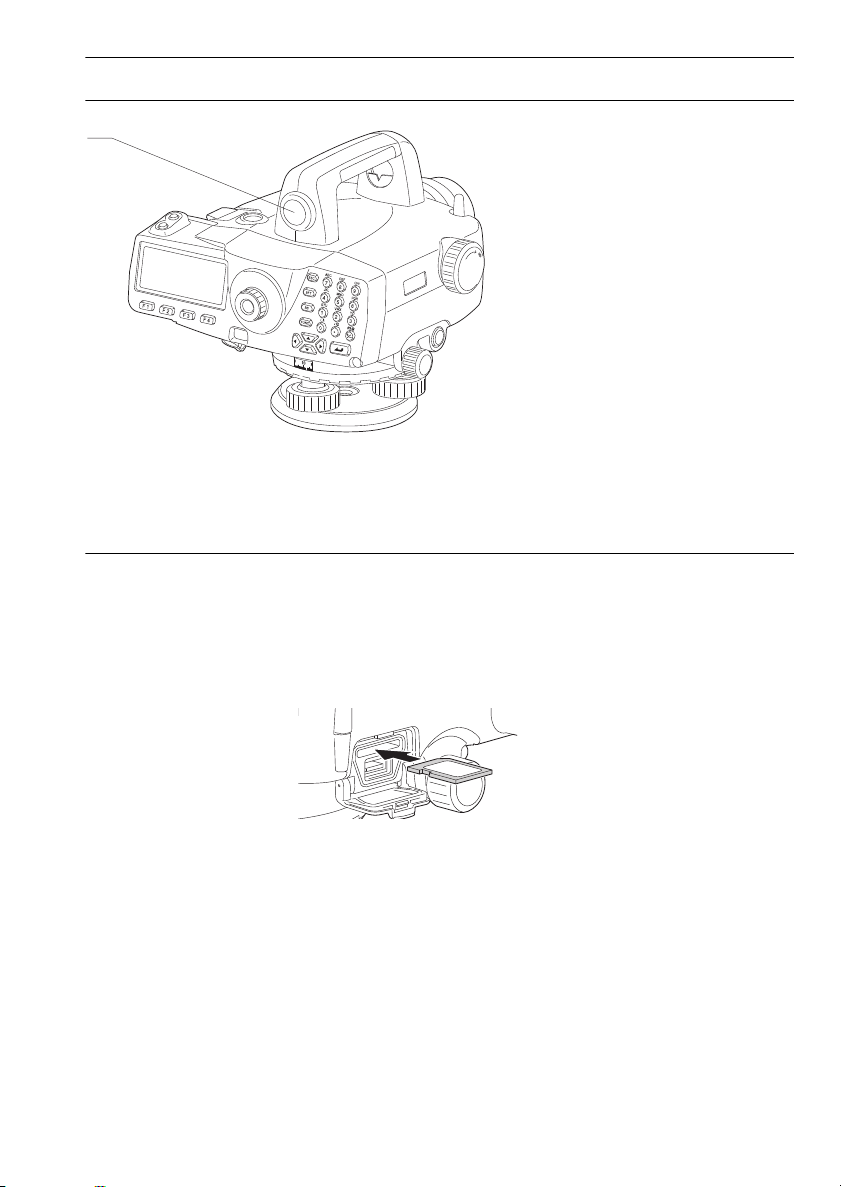
SD card slot
The DL supports SD/SDHC cards (hereafter referred to collectively as "SD card" unless
otherwise stated) for data write only. The SD card slot is located in the external interface hatch.
Inserting an SD card
An SD card should be inserted with the contacts facing downwards.
Removing an SD card
Push an inserted SD card further into the slot and release to eject.
7
Page 16
3. PRODUCT OUTLINE
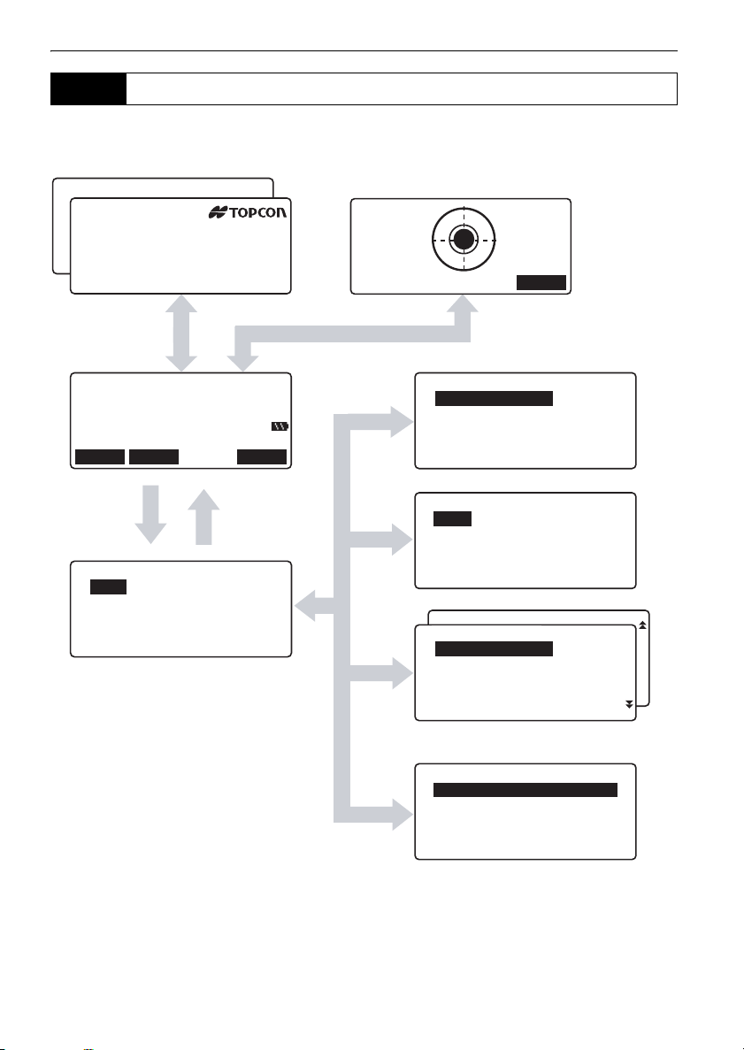
3.2 Mode Structure
The diagram below describes the different modes of the DL and key operations for navigating between
them.
Job: JOB1
Route: ec.remainder
DL-501 Adv
Meas.pt: 9995
S/N 999999
Start info: 997 ( 99)
Appli :Ver.XXXX-XX-XX
Fixed pt: 1997( 98)
Sensor:Ver.XXXX-XX-XX
Feb/03/2012 14:23:34
Status Screen Tilt Screen
{ESC}
{ESC}
[OK]
[TILT]
OK
Rh
Hd S
TILT MENU FOCUS
Meas mode
[MENU]
{ESC}
Menu
1.Meas
2.Management
3.Config
4.Calculation
1.Meas
2.Management
{ESC}
3.Config
4.Calculation
Meas menu
1.Height dif.
2.Check & adjust.
3.Simple measurement
Management menu
1.JOB
2.Route
3.Known point data
4.Simple meas. data
Config menu
Config menu
1.Obs.condition
2.Instr.config
3.Comms setup
4.Tilt offset
5.Unit
Calculation menu
1.Dble-run discrePancy
2.Closure error
3.Reobs.route merge
.
8
Page 17

3. PRODUCT OUTLINE
3.3
• Bluetooth communication is only possible with instruments incorporating the Bluetooth module.
• Use of this technology must be authorized according to telecommunications regulations of the
country where the instrument is being used. Contact your local dealer in advance.
Bluetooth
Wireless Technology
"26. REGULATIONS"
• TOPCON CORPORATION is not liable for the content of any transmission nor any content related
thereto. When communicating important data, run tests beforehand to ascertain that communication
is operating normally.
• Do not divulge the content of any transmission to any third party.
Radio interference when using Bluetooth technology
Bluetooth communication with the DL uses the 2.4 GHz frequency band. This is the same band used
by the devices described below.
•Industrial, scientific, and medical (ISM) equipment such as microwaves and pacemakers.
• portable premises radio equipment (license required) used in factory production lines etc.
• portable specified low-power radio equipment (license-exempt)
•IEEE802.11b/IEEE802.11g standard wireless LAN devices
The above devices use the same frequency band as Bluetooth communications. As a result, using the
DL within proximity to the above devices may result in interference causing communication failure or
reduction of transmission speed.
Although a radio station license is not required for this instrument, bear in mind the following points
when using Bluetooth technology for communication.
Regarding portable premises radio equipment and portable specified low-power radio
equipment:
• Before starting transmission, check that operation will not take place within the vicinity of portable
premises radio equipment or specified low-power radio equipment.
• In the case that the instrument causes radio interference with portable premises radio equipment,
terminate the connection immediately and take measures to prevent further interference (e.g.
connect using an interface cable).
• In the case that the instrument causes radio interference with portable specified low-power radio
equipment, contact your local dealer.
When using the DL in proximity to IEEE802.11b or IEEE802.11g standard wireless LAN
devices, turn off all devices not being used.
• Interference may result, causing transmission speed to slow or even disrupting the connection
completely. Turn off all devices not being used.
Do not use the DL in proximity to microwaves.
• Microwave ovens can cause significant interference resulting in communication failure. Perform
communication at a distance of 3m or more from microwave ovens.
Refrain from using the DL in proximity to televisions and radios.
• Televisions and radios use a different frequency band to Bluetooth communications.
9
Page 18

3. PRODUCT OUTLINE
However, even if the DL is used within proximity to the above equipment with no adverse effects
with regard to Bluetooth communication, moving a Bluetooth compatible device (including the DL)
closer to said equipment may result in electronic noise in sound or images, adversely affecting the
performance of televisions and radios.
Precautions regarding transmission
For best results
• The usable range becomes shorter when obstacles block the line of sight, or devices such as PDAs
or computers are used. Wood, glass and plastic will not impede
range becomes shorter. Moreover, wood, glass and plastic containing metal frames, plates, foil and
other heat shielding elements as well as coatings containing metallic powders may adversely affect
Bluetooth
• Use a vinyl or plastic cover to protect the instrument from rain and moisture. Metallic materials
should not be used.
• The direction of the Bluetooth antenna can have adverse effects upon usable range.
Reduced range due to atmospheric conditions
The radio waves used by the DL may be absorbed or scattered by rain, fog, and moisture from the
human body with the limit of usable range becoming lower as a result. Similarly, usable range may
also shorten when performing communication in wooded areas. Moreover, as wireless devices lose
signal strength when close to the ground, perform communication at as high a position as possible.
communication and concrete, reinforced concrete, and metal will render it impossible.
communication but the usable
10
Page 19

4. BASIC OPERATION
OFF
{0} to {9}
{ }
{ } { } { }
{ }
{ }
{ }
{.} to {+/-}
Display
{FUNC}
{BS}
{SFT}
{ESC}
Softkey selection
Measure key
Learn basic key operations here before you read each measurement procedure.
4.1 Basic Key Operation
Power ON/OFF
{} (Press and hold)
{} while pressing {}
Switching screen/key backlight ON/OFF
{} Switches the screen backlight/key backlight ON/OFF
Power ON
Power OFF
Measurement (Auto Focus)
Automatically focuses on the staff and starts measurement. (DL-
Measure key
501 Advanced)
Starts measurement (DL-501 Standard)
Softkey operation
Softkeys are displayed on the bottom line of the screen.
{F1} to {F4} Select the function matching the softkeys
{FUNC} Toggle between softkey pages
Inputting letters/figures
{SFT} Switch between numeric and alphabetic (upper/lower case)
characters.
{0} to {9} Input numeral or symbol printed above the key (during numeric
input mode)
Input alphabetic character in the order they are listed (in
alphabetic input mode)
{.} Input a decimal point (during numeric input mode)
{+/-} Input a plus or minus sign (during numeric input mode)
{}/{} Right and left cursor/Select other option.
{ESC} Cancel the input data.
11
Page 20
4. BASIC OPERATION
OK
Route id
: ROUTE M
Memo
:
:
A
{BS} Delete a character on the left.
{} Select/accept input word/value.
Selecting options
{
}/{} Move the cursor/selection item up/down
{}/{} Move the cursor/selection item left/right or select other option
{} Select/accept the option
Other operation
{ESC} Return to previous screen
Example :Entering "Route M" in the Route ID field
1. Press {6} three times.
"R" is displayed.
2. Press {5} three times.
"O" is displayed.
3. Press {1} three times.
"U" is displayed.
4. Press {} once.
5. Press {1} twice.
"T" is displayed.
6. Press {8} twice.
"E" is displayed.
7. Press {} twice.
Input a blank space.
8. Press {5} once.
"M" is displayed. Press { } to complete
inputting.
.
12
Page 21
4. BASIC OPERATION
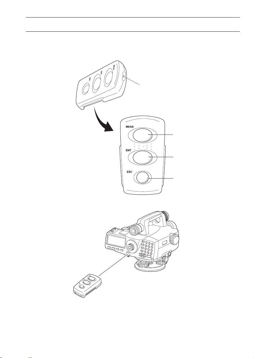
{MEAS}
{ENT}
{ESC}
Beam source
Key panel
Remote operation
Key operation for Remote trigger (DLC1A)
DLC1A comes as standard with the DL-501 Advanced and is an optional accessory for the DL-501
Standard.
"4.1 Basic Key Operation"
The DL is operated from the Remote trigger by pointing the Remote trigger beam at the DL and
pressing the required operation keys.
• When sunlight shines directly into the Beam detector on the DL, remote operation with the Remote
trigger may not work correctly.
13
Page 22

4. BASIC OPERATION
• If other DLC1A-compatible instruments are turned ON and placed within the operating range of the
Remote trigger, they may be unintentionally operated at the same time.
• Do not place the Remote trigger under heavy objects or in a tight space. A key may be continuously
depressed and deplete battery power.
• Working duration shortens under low temperatures.
{MEAS} Performs same operation as Measure key on the
DL
{ENT} Same operation as {} on DL
{ESC} Same operation as {ESC} on DL
14
Page 23
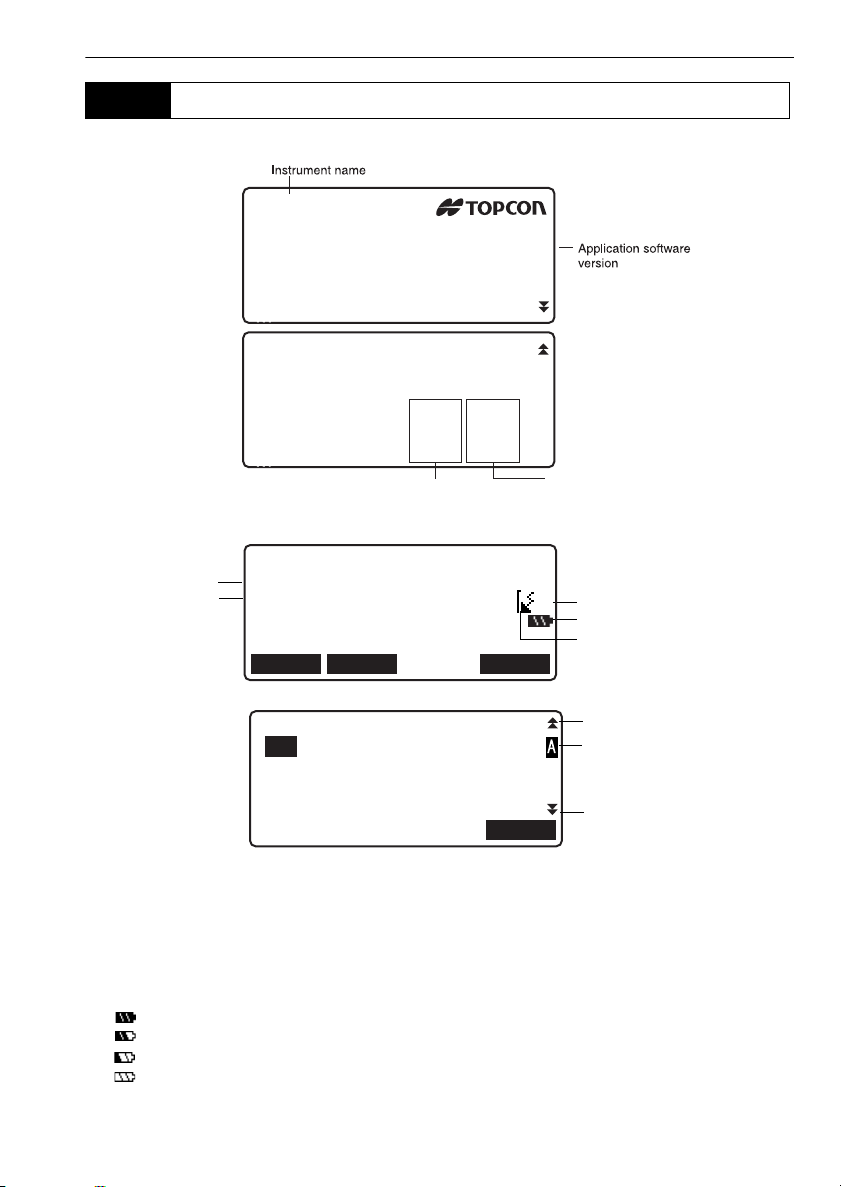
4.2 Display Functions
DL-501 Adv
S/N 999999
Appli :Ver.XXXX-XX-XX
Sensor:Ver.XXXX-XX-XX
Feb/03/2012 14:23:34
Job: XXXX
Route:XXXX
Rec.remainder
Meas.pt: XXXX(XXX)
Start info: XXXX(XXX)
Fixed pt: XXXX(XXX)
Available memory
(current route)
Available memory
(total)
*1
*2
*3
*4
Rh
Hd S
TILT MENU FOCUS
*5
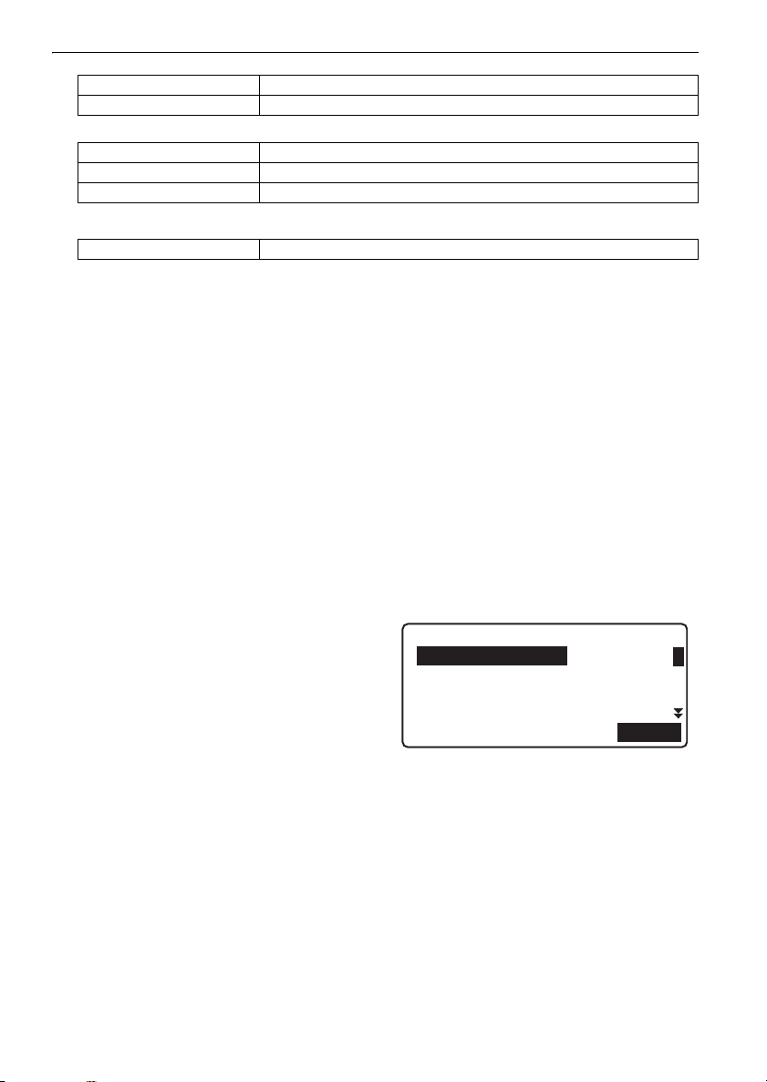
End bench mark id
:B2
End bench mark elev.
: 165.00000m
OK
Previous page
Next page
*6
Status screen
Meas Mode screen
4. BASIC OPERATION
Input screen
*1 Rh: Staff reading (height)
*2 Hd: Horizontal distance to staff
*3 Measurement mode
S: Single
R: Repeat
A: Average
T: Rapid
* 4 Remaining battery power (BDC58/70, Temperature=25°C)
: level 3 Full power.
: level 2 Plenty of power remains.
: level 1 Half or less power remains.
: level 0 Little power remains. Prepare replacement battery where available.
15
Page 24

4. BASIC OPERATION
"Battery low! Please charge battery." (with audio tone) displayed alternately with current screen
: No power remains.
Stop measurement and save data. Then turn the instrument off and charge the battery.
"5.1 Battery Charging"
*5 Bluetooth communication status
: Connection established
(flashing): Waiting
(flashing): Disconnecting
:DL Bluetooth device is OFF
*6 Input mode
A :Inputting capital letters
a :Inputting small letters
1 :Inputting numeric characters
16
Page 25
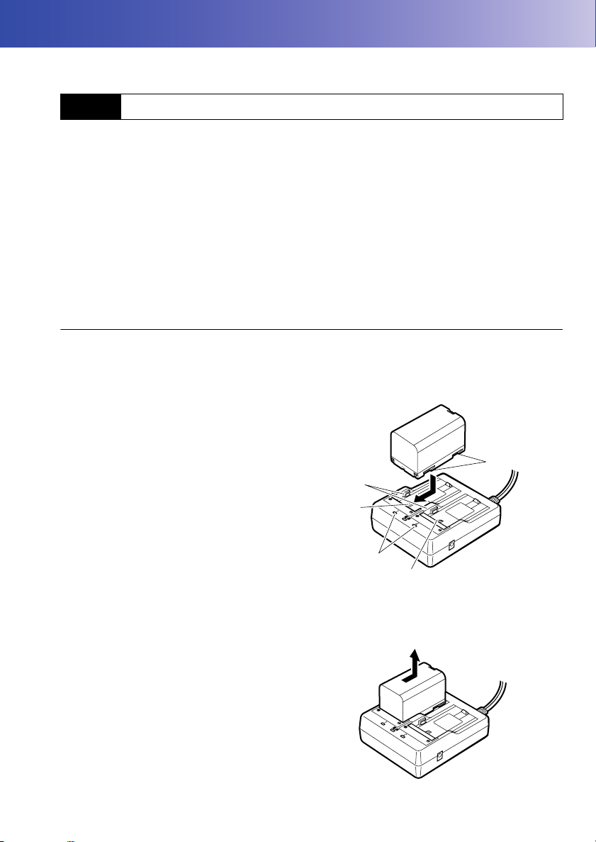
5. USING THE BATTERY
Guides
Slot 1
Slot 2
Charging
lamp
Grooves
Types of power source: "22. POWER SUPPLY SYSTEM"
5.1 Battery Charging
The battery was not charged at the factory. Charge the battery fully before using the DL.
• The charger will become rather hot during use. This is normal.
• Do not use to charge batteries other than those specified.
• The charger is for indoor use only. Do not use outdoors.
• Batteries cannot be charged, even when the charging lamp is flashing, when the temperature is
outside the charging temperature range.
• Remove batteries from the charger before putting into storage.
• When not in use, disconnect the power cable plug from the wall outlet.
PROCEDURE
1. Connect the power cable (EDC113A/113B/
113C) to the charger (CDC68/68A) and plug
the charger into the wall outlet.
2. Mount the battery in the charger by matching
the grooves on the battery with the guides on
the charger.
3. When charging starts, the lamp starts blinking.
4. The lamp lights when charging is finished.
5. Remove the battery and unplug the charger.
17
Page 26
5. USING THE BATTERY
• Slots 1 and 2:
The charger starts charging the battery mounted first. If you place two batteries in the charger, the
battery in slot 1 is charged first, and then the battery in slot 2. ( step 2)
• Charging lamp:
The charging lamp is off when the charger is outside the charging temperature range or when the
battery is mounted incorrectly. If the lamp is still off after the charger falls within its charging
temperature range and the battery is mounted again, contact your local dealer. (steps 2 and 3)
• Charging time per battery (at 25°C):
BDC58: about 4 hours
BDC70: about 5.5 hours
(Charging can take longer than the times stated above when temperatures are either especially
high or low.)
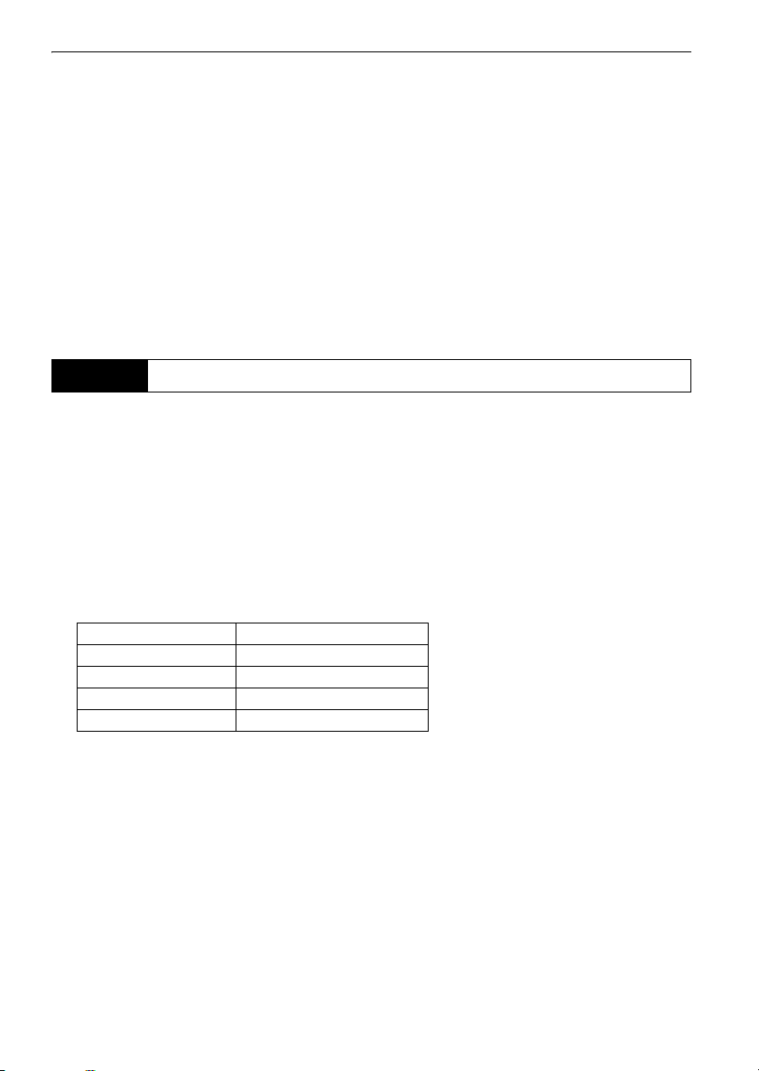
5.2 Installing/Removing the Battery
Mount the charged battery.
BDC46C and battery adapter SB178 are optional accessories.
• Before removing the battery, turn off the power to the instrument.Settings, and file and folder data
may be lost if the battery is removed while the power is switched on.
• When installing/removing the battery, make sure that moisture or dust particles do not come in
contact with the inside of the instrument.
• Remove batteries from the instrument or charger before putting into storage.
• Store the battery in a dry room where the temperature is within the following ranges
Storage period Temperature range
1 week or less -20 to 50°C
1 week to 1 month -20 to 45°C
1 month to 6 months -20 to 40°C
6 months to 1 year -20 to 35°C
For long-term storage, the battery should be charged at least once every six months.
• The BDC58/70 generates power using a chemical reaction and as a result has a limited lifetime.
Even when in storage and not used for long periods, battery capacity deteriorates with the passage
of time. This may result in the operating time of the battery shortening despite having been charged
correctly. In this event, a new battery is required.
18
Page 27
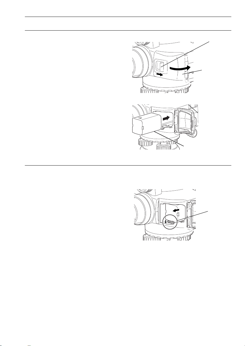
PROCEDURE Mounting the battery
Battery cover
Catch
Battery
Release
lever
1. Push the catch on the battery cover away from
the objective lens.
2. Insert the battery in the direction of the arrow
on the side of the battery.
3. Close the battery cover. A click is heard when
the cover is secure.
PROCEDURE Removing the battery
1. Push the catch on the battery cover away from
the objective lens.
5. USING THE BATTERY
2. Push the release lever down. Grip the battery
and slide out.
• If the release lever is not pushed down
completely when removing the BDC46C, the
battery adapter may jam against the release
lever. In this event, push the lever down fully
and remove, or re-insert the battery into the
instrument and try removing again.
3. Close the battery cover. A click is heard when
the cover is secure.
19
Page 28
5. USING THE BATTERY
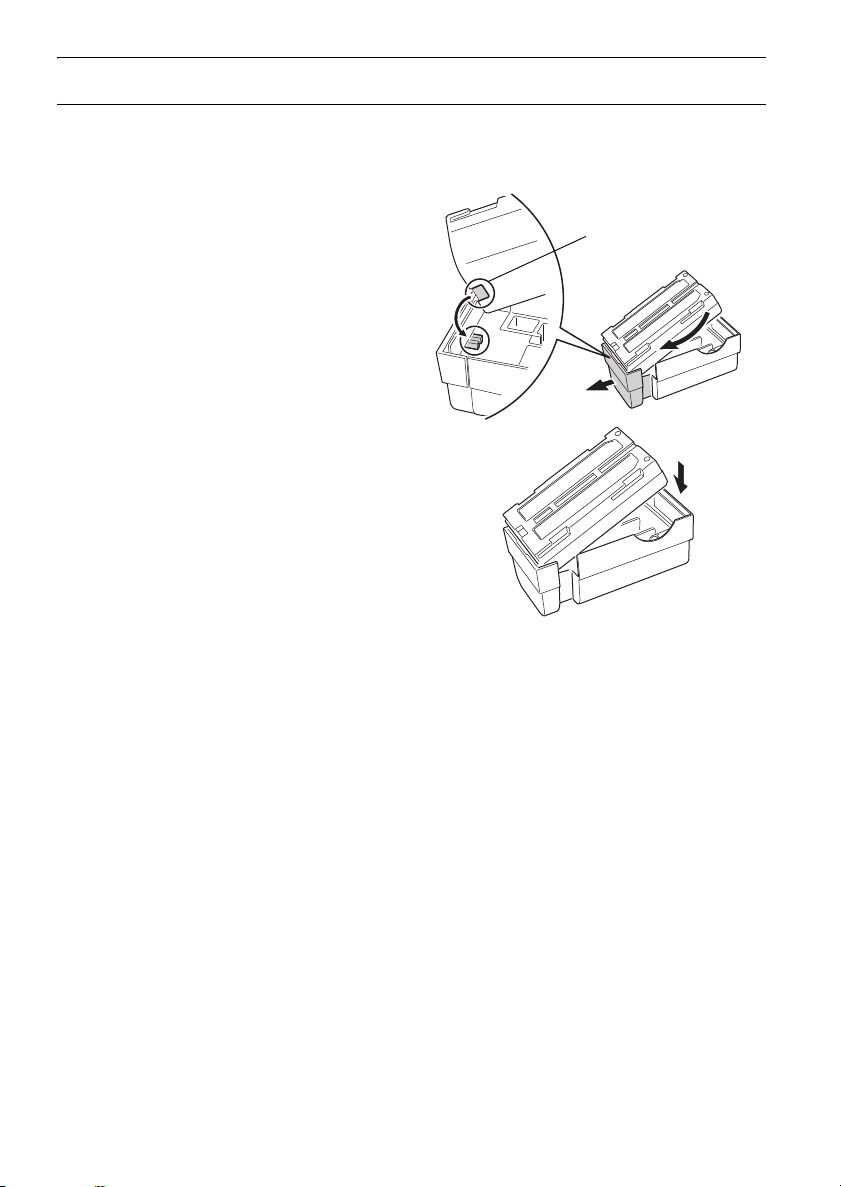
Battery notch
PROCEDURE Using the Battery adapter
Insert the BDC46C into the battery adapter (SB178). The battery can now be mounted in the same
way as the BDC58/70.
1. Align the notch in the BDC46C with the SB178
as shown at right. With the terminals-end of
the battery inserted, push until the battery
adapter is fully extended.
2. Slot the top end of the battery into the battery
adapter. The extendable portion of the battery
adapter will automatically retract and hold the
battery in place.
• To remove, grip both sides of the battery towards
the terminals-end and pull out.
• It is possible to charge the BDC46C without
removing from the battery adapter.
20
Page 29
6. SETTING UP THE INSTRUMENT
Bubble
mirror
• Mount the battery in the instrument before performing this operation because the instrument will tilt
slightly if the battery is mounted after leveling.
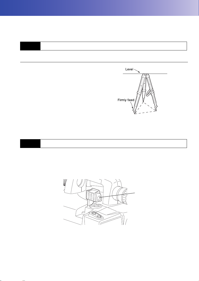
6.1 Setting Up
PROCEDURE
1. Make sure the legs are spaced at equal
intervals and the head is approximately level.
Set the tripod so that the head is positioned over
the survey point.
Make sure the tripod shoes are firmly fixed in the
ground.
2. Place the instrument on the tripod head.
Supporting with one hand, tighten the centering
screw on the bottom of the unit to make sure it is
secured to the tripod.
6.2 Leveling
Instrument can also be levelled using the screen.
“ Leveling on the screen”
The mirror can be used to check the position of the bubble in the tube when it cannot be viewed from
above.
21
Page 30
6. SETTING UP THE INSTRUMENT
Spherical head
tripod
Centering
screw
Tripod legs
adjustment
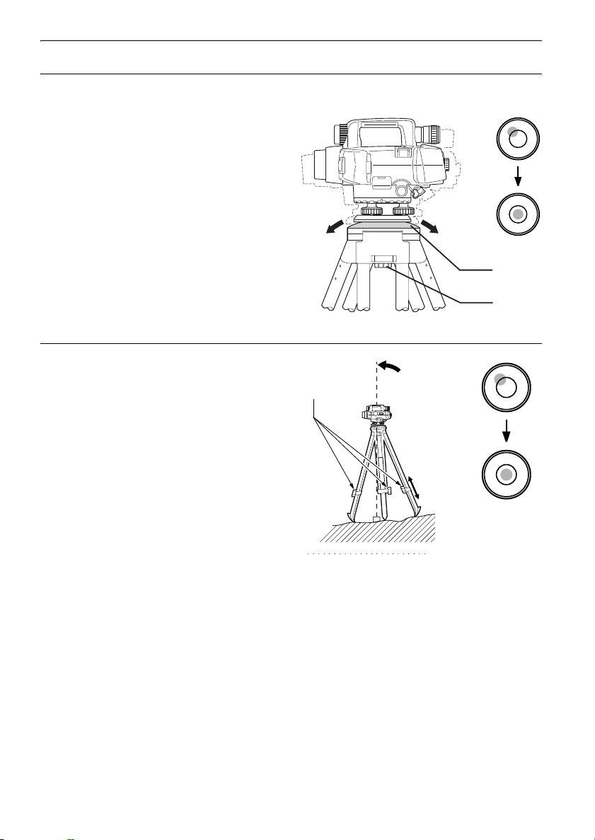
PROCEDURE Leveling with the Spherical head tripod
1. Loosen the centering screw.
2. Slide the instrument across the tripod head until
the bubble is centered in the circular level.
3. Tighten the centering screw.
4. Level the DL using the leveling foot screws.
PROCEDURE Leveling with the Flat head tripod
1. Center the bubble in the circular level by either
shortening the tripod leg closest to the offcenter
direction of the bubble or by lengthening the
tripod leg farthest from the offcenter direction of
the bubble.
2. Adjust one more tripod leg until the bubble is
roughly centered.
3. Turn the leveling foot screws while checking the
circular level until the bubble is exactly centered
in the center circle. When you turn a screw
clockwise, raising the instrument, the bubble will
move towards the position of that screw.
22
Page 31

6. SETTING UP THE INSTRUMENT
OFF
MENU
PROCEDURE Leveling on the screen
1. Turn the instrument on.
"7. POWER ON/OFF"
2. The screen shown at right is displayed.
3. Center “” in the circular level.
"6.2 Leveling PROCEDURE Leveling
with the Spherical head tripod/"6.2 Leveling
PROCEDURE Leveling with the Flat head
tripod"
“” indicates the bubble in circular level. The
range of the inside circle is 12' and the range of
the outside circle is 24’.
•Press [OFF]/[BEEP] to turn the audio tone
OFF/ON.
• Measurement cannot be performed when the Tilt screen is displayed.
• The tilt screen is automatically displayed on startup when "Tilt warn" in "Obs.condition" is set to
"Yes" and the instrument tilt exceeds the allowable range. Set to "No" to skip levelling on startup.
"Tilt warn." setting: "19.2 Instrument Configuration"
•Pressing [MENU] in the screen shown above returns the screen to <Menu> without completing
leveling. However, measurement cannot be performed until the instrument is levelled.
23
Page 32

7. POWER ON/OFF
Rh
Hd S
TILT MENU FOCUS
PROCEDURE Power ON
1. Press {}.
When the power is switched on, a RAM check
is run. The Meas mode screen is displayed.
If the tilt screen is displayed, the instrument tilt
sensor is indicating that the instrument is out of
level. Level the instrument once again and the
Meas mode screen will be displayed.
• The tilt screen is automatically displayed on startup when "Tilt warn" in "Obs.condition" is set to "Yes"
and the instrument tilt exceeds the allowable range. Set to "No" to skip levelling on startup.
• Do not remove the battery while the TOPCON logo is displayed.
• "Tilt warn." in "Obs. condition" should be set to "No" if the display is unsteady due to vibration or
strong wind.
"19.1 Observation Conditions"
Resume function
The Resume function redisplays the screen appearing before the instrument was powered OFF
when the instrument is powered back ON. All parameter settings are also saved. This function
is only activated when the power is turn off while performing height difference measurement or
checks and adjustments. When powering back on the screen is returned to the beginning of the
procedure being performed on power OFF.
PROCEDURE Power OFF
Press {} while pressing {}.
• When there is almost no battery power remaining, "Battery low! Please charge battery." (with
audio tone) is displayed alternately with current screen. In this event, stop measurement, switch
off the power and charge the battery or replace with a fully charged battery. Data and settings
may be lost if the battery is removed while the power is on.
• To save power, power to the DL is automatically cut off if it is not operated for a fixed period of
time. This time period can be set to "30 min." or "No" in "Power off" in "Instr.config".
"19.2 Instrument Configuration"
24
Page 33

7. POWER ON/OFF
7.1 Resolving Software Issues
If you are experiencing problems with the DL and suspect a fault in the software, you should try
resetting. If the problem is not resolved the next step is to initialize data.
"19.6 Restoring Default Settings"
• Be sure to back up stored data to an external memory device or computer in advance.
PROCEDURE Initializing data
1. Power OFF the instrument.
2. Press
{}
{F3} until the TOPCON logo appears.
"Clearing memory..." is displayed and data is
initialized. The instrument then powers on as
normal.
while holding {BS}, {F1}, and
25
Page 34

8.
FOCUSING AND SIGHTING THE STAFF
8.1 Using the DL-501 Advanced
•If the view finder sighting axis is not aligned with the sighting axis of the objective lens, errors will
occur when taking measurements. Always make sure the axes are correctly aligned when using
the view finder.
•The View finder can be used to sight staffs at distances of 7m or more.
•Focussing can also be performed manually by turning the focusing knob while looking through
the eyepiece. If the staff barcodes are out of focus, they will not be readable and measurements
cannot be taken. Make sure they are correctly focused.
•Even when Auto Focus has finished the image in the telescope eyepiece may appear out of
focus depending on the eyesight of the operator.
View finder and Auto Focus function
The view finder is used when aligning the DL telescope with the staff. Simply aligning the two
center circles in the view finder with the center of the staff and pressing the Measure key
automatically focuses the DL on the staff and starts measurement reducing operator workload
and increasing operator efficiency in the field.
PROCEDURE Always perform before using the instrument
1. Look through the telescope at a bright and
featureless background.
2. Looking through the eyepiece, turn the eyepiece
screw clockwise, then counterclockwise little by
little until just before the reticle image becomes
focussed.
Using these procedures, frequent reticle
refocussing is not necessary since your eye is
focussed at infinity.
3. Looking through the telescope, shift your eyes
slightly up and down and to each side. If the
staff and reticle show no deviation, the
instrument is ready for use.
If the staff and reticle deviate, return to step 2.
4. Sight a clear vertical line, such as the wall of a
building, at a distance usually used for
operation.
26
Page 35

8. FOCUSING AND SIGHTING THE STAFF
5. Turn the horizontal fine motion knobs until that
vertical line is centered in the field of view.
6. Looking through the view finder, turn the view
finder eyepiece screw until the 2 circles are
focussed.
7. Use the view finder axis alignment screw to
align the 2 circles in the view finder with the
same vertical line described in step 4.
The sighting axis of the view finder is now
aligned with the sighting axis of the telescope
as seen through the eyepiece.
Eliminating parallax
This is the relative displacement of the target image with respect to the reticle when the
observer’s head is moved slightly before the eyepiece.
Parallax will introduce reading errors and must be removed before observations are taken.
Parallax can be removed by refocussing the reticle.
PROCEDURE Using Auto Focus to focus on the staff
1. Turn the instrument on.
"7. POWER ON/OFF"
2. Aim the objective lens roughly in the direction of
the staff.
3. Use the horizontal fine motion knobs to align the
2 circles in the view finder until the staff is
approximately centered.
4. Press the Measure key. The instrument
automatically focuses on the staff and
measurement starts.
27
Page 36

8. FOCUSING AND SIGHTING THE STAFF
8.2 Using the DL-501 Standard
• If the staff barcodes are out of focus, they will not be readable and measurements cannot be
taken. Makes sure they are correctly focused.
PROCEDURE
1. Look through the telescope at a bright and
featureless background.
2. Looking through the eyepiece, turn the
eyepiece screw clockwise, then
counterclockwise little by little until just before
the reticle image becomes focussed.
Using these procedures, frequent reticle
refocussing is not necessary since your eye is
focussed at infinity.
3. Use the Simple Finder to point the objective
lens at the staff.
4. Turn the horizontal fine motion knobs until the
staff is nearly centered in the field of view, then
turn the focusing knob to focus on the staff.
5. Looking through the telescope, shift your eyes
slightly up and down and to each side. If the
staff and reticle show no deviation, the
instrument is ready for use.
If the staff and reticle deviate, return to step 2.
"8.1 Using the DL-501 Advanced
Eliminating parallax"
•Repeat steps 3 and 4 each time measurement is performed.
28
Page 37

9. CONNECTING TO EXTERNAL DEVICES
Menu
1.Meas
2.Management
3.Config
4.Calculation
Config menu
1.Obs.condition
2.Instr.config
3.Comms setup
4.Tilt offset
5.Unit
INFO
Mode :Bluetooth
Authenticate:No
STX/ETX(CSV):No
The DL can be connected to a data collector to allow remote operation. Read this manual in
conjunction with the operator’s manual for the relevant external device and software thereof.
9.1
The Bluetooth module incorporated in the DL can be used for communication with Bluetooth devices
such as data collectors.
Wireless Communication using Bluetooth Technology
• Connection settings are returned to factory settings when defaults are restored. Perform settings
again after restoring defaults.
Bluetooth connections
Communication between a pair of Bluetooth devices requires one device to be set as the
"Master" and the other as the "Slave". DL is always the "Slave" device. Connections are initiated
from the paired device side
PROCEDURE Necessary settings for Bluetooth communication
1. Select "Config" in <Menu>.
2. Select "Comms setup" in <Config menu>.
3. Select "Bluetooth" in "Mode".
4. Set "Authenticate" to "Yes" or "No".
If "Authenticate" is set to "Yes" for the DL the
passkey will also need to be input on the
companion device.
29
Page 38

9. CONNECTING TO EXTERNAL DEVICES
INFO
Mode :Bluetooth
Authenticate:Yes
Passkey
:****
STX/ETX(CSV):No
AVG out mode:1
INFO
Mode :Bluetooth
Authenticate:No
STX/ETX(CSV):No
Bluetooth ID
: Bxxxxxx,Bxxxxxx
Firmware Ver.x.x.x
BD_ADDR
: 00:AA:BB:CC:DD:FF
OK
5. When "Authenticate" is set to "Yes", input the
same passkey as that for the intended
companion device. Even if "Authenticate" is
set to "No", a passkey is requested when
authentication is set on the companion device
being used.
Up to 16 numeral characters can be input.
Input characters will be displayed as asterisks
(e.g. "*****"). The passkey was set to "0123" at
the factory.
6. Set STX/ETX (CSV) settings
"19.3 Communication Setup STX/
ETX (CSV)"
7. Set average output mode
"19.3 Communication Setup AVG o ut
mode"
PROCEDURE Displaying Bluetooth information for the DL
1. Select "Config" in <Menu>
2. Select "Comms setup" in <Config menu>
3. Select "Bluetooth" in "Mode" and press
[INFO].
The Bluetooth information for the DL is
displayed. The "BD_ADDR" for the DL must be
registered on your Bluetooth device.
30
Page 39

9. CONNECTING TO EXTERNAL DEVICES
Rh
Hd S
P2
Bluetooth Device Address
This is a number unique to one particular Bluetooth device used to identify devices during
communication. This number consists of 12 characters (numbers 0 to 9 and letters from A to F).
Some devices may be referred to by their Bluetooth device address.
9.2
Establishing a connection between the DL and paired
Bluetooth device
When "Mode" is set to "Bluetooth" in "Comms setup" in <Config menu> [ ]/[ ] is
displayed in Meas mode.
PROCEDURE
1. Complete the necessary settings for Bluetooth
communication.
"9.1 Wireless Communication using
Bluetooth Technology"
2. Press [] in the second page of Meas
mode screen.
The Bluetooth module in the DL powers on and
connection starts.
The Bluetooth icon indicates communication
status.
"4.2 Display Functions"
• Softkeys (in Meas mode)
[]:Press to enter waiting status
[]:Press to cancel the connection/exit waiting status
• Audio tones
(While connecting/disconnecting)
Start paging/waiting: short beep
Connection successfully established: long beep
Connection canceled/being canceled: two short beeps
31
Page 40

9. CONNECTING TO EXTERNAL DEVICES
9.3
Setting a data collector as the companion device allows measurement and other operations to be
performed from the data collector side.
Communication between the DL and Companion Device
•
Bluetooth
normal operation.
• Check that the companion device (data collector etc.) is turned on and the relevant Bluetooth
settings are complete.
PROCEDURE
1. Complete the necessary settings for Bluetooth
2. Check communication status.
3. Initiate measurement using the paired
communication causes DL battery power to be depleted at a rate higher than that for
communication.
"9.1 Wireless Communication using
Bluetooth Technology"
"9.2 Establishing a connection between
the DL and paired Bluetooth device"
Bluetooth device (e.g. a data collector). DL will
respond and measurement will start.
Measured values are then displayed in the
Meas mode screen.
9.4
It is possible to set a computer as the companion device and output JOB data and route data via
wireless communication.
Outputting data using Bluetooth communication
PROCEDURE Outputting JOB data to a host computer
1. Complete the necessary settings for Bluetooth
communication.
"9.1 Wireless Communication using
Bluetooth Technology"
2. Check communication status.
"9.2 Establishing a connection between
the DL and paired Bluetooth device"
32
Page 41

9. CONNECTING TO EXTERNAL DEVICES
Job id
JOB1
Format CSV_1
Outputting 98/ 99
Bluetooth
Waiting for
connection...
3. Select "Comms output" in <JOB menu> and
set "Com.locat."
"18.1 Outputting JOB Data PROCEDURE
Outputting JOB data to host computer"
DL starts outputting data.
• If a connection has not yet been established,
the screen at right is displayed. After a
connection has been established, the data is
output.
9.5 Connecting via Communication Cable
PROCEDURE Basic cable settings
1. Connect the DL to the external device using
the cable.
Cables:
"24. OPTIONAL
ACCESSORIES"
2. Select "Comms setup" in <Config menu>.
Set communication conditions.
"19.3 Communication Setup"
33
Page 42

10.BASIC OPERATION
ΔαΔ
Δ
10.1 Reading the Staff
Simply focus on the RAB* code for an automatic reading of the staff. The following explains how to
read the RAB code of the staff.
*RAB code (RAndom Bi-directional code) is a coded staff used with certain digital levels.
• Set up the staff in an area free of obstacles.
• Avoid placing the staff next to mirror-like surfaces. The effect of strong light could make
measurements impossible.
• Support the staff so that it is perpendicular, checking the circular bubble scope on the staff. If the
staff is tilting, height and distance measurements will be incorrect.
• If the surface is catching the light, turn it just enough to stop the reflection.
• Make sure shadows are not cast on the staff as this could make measurement impossible.
• When holding the staff during measurement, make sure your hand does not cover the RAB code.
• If dark locations make measurement difficult, shine a flashlight on the staff. Stand at a distance so
that the beam shines evenly over the length of the staff.
• If waterdrops or dirt adhere to the barcode, measurement may be impossible. Wipe the staff clean
with a soft cloth.
• Clean the staff if grit or dirt gets stuck between the sections. If the staff is dirty, measurements will
not be very accurate.
• Avoid scratching or soiling the barcode surface as this could make measurement impossible. Store
and carry the staff inside its case.
• If the BIS/BGS series staff is used for leveling, and the height difference and temperature difference
are much larger than normal, temperature variations may cause the staff to expand or contract and
cause differences in relative height measurements. DL reads in measurements up to 0.01mm and
minor deviations in the accuracy of the staff will adversely affect accuracy. To obtain high accuracy
measurements, it is important to perform temperature corrections for the staff. See below.
• Formula for correcting expansion and contraction of the staff due to temperature changes.
C={C0+(T-T0)x }x h
C: Staff correction value
C0: Scale factor
T: Measured temperature during observation (average
temperature during measurement of known site,
34
Page 43

intermediate site, new site)
°
α
Δ
Rh "negative value"
Inverted staff
T0: Reference temperature of 20 C
: Line expansion coefficient
h: Height difference
PROCEDURE Setting up the staff
1. Set the foot plate on the ground so that the
staff will not sink.
2. When using a BGS staff, connect the sections
correctly by making sure the numbers on the
numeric scale side of the staffs run in
unbroken order.
3. Keeping an eye on the circular bubble scope
on the staff, set the staff in the foot plate so
that it stands up straight.
4. Turn the barcode scale towards the instrument.
PROCEDURE Measuring the height from a ceiling
10. BASIC OPERATION
35
Page 44

10. BASIC OPERATION
A
Rh
Hd
FOCUS
Rh 1.2345 m
Hd 4.321 m
MENUTILT
S
10.2 Measuring in Measure Mode
In Measure mode you can sight point A, take the staff reading Rh, and measure the horizontal distance
Hd to the staff.
• If direct sunlight or strong light enter the eyepiece during measurement, ambient light is too low, or
the staff is set against a background which is too bright, and measurement cannot be performed, an
error is displayed (
• If the DL or staff is subjected to shocks or vibration during use, measurement may be impossible.
Resume measurement during more stable conditions.
PROCEDURE
"20. WARNING AND ERROR MESSAGES").
1. Turn the instrument on.
"7. POWER ON/OFF"
2. Aim the instrument at the staff and press the
Measure key. Measurement starts. When
measurement is complete, the staff readings
(Rh) and horizontal distance (Hd) are
displayed.
• In Repeat, Average, or Rapid mode, values
are renewed with each measurement. Press
[STOP] or the Measure key to stop reading.
Press {ESC} to cancel the reading.
•Auto focus functionality is not available for the DL-501 Standard. Therefore [FOCUS] is not
displayed in the screen of step 2.
36
Page 45

11.SIMPLE MEASUREMENT
A
B
dH
Menu
1.Meas
2.Management
3.Config
4.Calculation
Meas menu
1.Height dif.
2.Check & adjust.
3.Simple measurement
Simple meas. menu
1.Ht-diff. meas.
2.Elevation meas.
3.View
4.Deletion
FOCUS
BS Go
BS0001
Rh
Hd
PT.ID
CNFGTILT
S
P1
This chapter explains how to measure height difference or elevation without setting a route.
•The maximum number of points per JOB is 2000.
11.1 Measuring Height Difference
This function allows the user to calculate the height difference (
foresight (B).
1. Select "Meas" in <Menu>.
2. Select "Simple measurement" in <Meas
menu>.
3. Select "Ht-diff. meas." in <Simple meas.
menu>.
dH) between backsight (A) and
4. Set up the DL between A and B.
5. Measure backsight.
• [FOCUS]: Press to perform Auto Focus only.
37
Page 46

11. SIMPLE MEASUREMENT
OK
Pt.id
:0000A
Meas.pt type:BS
Line :Go
Decr.
A.F.setting :Yes
Tilt warn :Yes
Meas mode :Single
Ht reso.
Dist reso.
:0.01mm
:0.001m
Auto rec :No
Data input
Rh : 0.00000m
Hd : 0.000 m
OK
1
OK
BS Go
BS0001
Rh 2.45678m
Hd 17.891 m
S
FOCUS
FS Go
FS0001
Rh
Hd
PT.ID
CNFGTILT
S
P1
• [PT.ID]: Press to change the current point ID.
Subsequent point IDs will be assigned
automatically in either ascending or
descending order.
Select [Decr.]/[Incr.] for descending/
ascending order.
• ( ) will be displayed to the right of the
point ID when ascending (descending)
order is selected.
•Point ID settings can be changed mid-route.
•[CNFG]: Press to configure measurement
settings.
• Press [INPUT] on page 2 to manually input
Rh values and Hd values obtained using the
telescope stadia lines.
6. Check point ID, double-run setting, and
measurement results.
Press [OK].
7. Measure foresight.
38
Page 47

8. Check point ID, double-run setting, and
OK
FS Go
FS0001
Rh 2.34567m
Hd 12.345 m
h -1.23456m
S
TURN P
FS Go
FS0001
Rh 2.34567m
Hd 12.345 m
h -1.23456m
S
"Auto rec" set to "No"
"Auto rec" set to "Yes"
FS Go
FS0001
Rh
Hd
TURN PINPUT
S
P2
YES
Operation will continue
from last measurement.
OK?
NO
measurement results.
Press [OK].
Results are recorded and the screen in step 7
is restored.
• When "Auto rec" is set to "Yes", results are
displayed for approx. 1 sec. before the
screen in step 7 is restored.
9. Press [TURN P] on page 2 to set the
previously measured foresight as a turning
point.
10. Move the DL to the next position.
Repeat from step 5 using the foresight
measured in step 7 as the new backsight.
11. SIMPLE MEASUREMENT
• When operation has been canceled after moving
screens during measurement, the following
message will be displayed the next time "Ht-diff.
meas." is selected in <Simple meas. menu>.
Press [YES] to resume measurement from
where you left off last time.
39
Page 48

11. SIMPLE MEASUREMENT
A
B
dH
HA + dH
0m
HA (Elevation
of known point)
Simple meas. menu
1.Ht-diff. meas.
2.Elevation meas.
3.View
4.Deletion
OK
BS
Z : 1.20000m
READ
1
FOCUS
BS Go
BS0001
Rh
Hd
PT.ID
CNFGTILT
S
P1
11.2 Measuring Elevation
This function allows the user to calculate the elevation (HA + dH) of a specified point (B) based on the
elevation of known point (A).
1. Select "Meas" in <Menu>.
2. Select "Simple measurement" in <Meas
menu>.
3. Select "Elevation meas." in <Simple meas.
menu>.
4. Set up the DL between A and B.
5. Input elevation of known point and press [OK].
•When elevation has been selected, press
[READ] to read in the elevation of a known
point.
• "12.3 Setting-Out Measurement
PROCEDURE Reading in recorded
known point data"
6. Measure backsight.
40
Page 49

7. Check point ID, double-run setting, and
OK
BS Go
BS0001
Rh 2.45678m
Hd 17.891 m
S
FOCUS
FS Go
FS0001
Rh
Hd
PT.ID
CNFGTILT
S
P1
OK
FS Go
FS0001
Rh 2.34567m
Hd 12.345 m
Z 1001.23456m
S
TURN P
FS Go
FS0001
Rh 2.34567m
Hd 12.345 m
Z 1001.23456m
S
"Auto rec" set to "No"
"Auto rec" set to "Yes"
FS Go
FS0001
Rh
Hd
TURN PINPUT
S
P2
measurement results.
Press [OK].
8. Measure foresight.
9. Check point ID, double-run setting, and
measurement results.
Press [OK].
Results are recorded and the screen in step 8
is restored.
• When "Auto rec" is set to "Yes", results are
displayed for approx. 1 sec. before the
screen in step 8 is restored.
11. SIMPLE MEASUREMENT
10. Press [TURN P] on page 2 to set the
previously measured foresight as a turning
point.
11. Move the DL to the next position.
Repeat from step 5 using the foresight
measured in step 8 as the new backsight.
41
Page 50

11. SIMPLE MEASUREMENT
YES
Operation will continue
from last measurement.
OK?
NO
Simple meas. menu
1.Ht-diff. meas.
2.Elevation meas.
3.View
4.Deletion
BS0000 BS
FS0001 FS
IS0002 IS
IS0003 IS
FIX0004 FIX
LAST
TOP
...P
SRCH
EDIT
BS Go
BS0000
Rh 2.45678m
Hd 17.891 m
PREV
NEXT
• When operation has been canceled after moving
screens during measurement, the following
message will be displayed the next time
"Elevation meas." is selected in <Simple meas.
menu>. Press [YES] to resume measurement
from where you left off last time.
11.3 Viewing Simple Measurement Data
It is possible to display measurement data obtained using simple measurement.
PROCEDURE
1. Select "Meas" in <Menu>.
2. Select "Simple measurement" in <Meas
menu>.
3. Select "View" in <Simple meas. menu>.
•Data can also be displayed via
<Management menu>
4. Align the cursor with the data to be displayed
and press {}.
Detailed information for the selected point is
displayed.
• [PREV]: Press to display detailed information
for the previous point.
• [NEXT]: Press to display detailed information
for the next point.
• [EDIT]: Press to edit point id and
measurement point type.
42
Page 51

11. SIMPLE MEASUREMENT
Search
Pt.id
:IS0003
OK
Simple meas. menu
1.Ht-diff. meas.
2.Elevation meas.
3.View
4.Deletion
BS0000
FS0001
IS0002
IS0003 DEL
FIX0004 DEL
LAST
TOP
...P
OK
P1
•Press [SRCH] to search for point data by
point id.
5. Press {ESC} to return to <Simple meas. data
menu>
11.4 Deleting Simple Measurement Data
It is possible to delete measurement data obtained using simple measurement.
PROCEDURE Deleting specific simple measurement data
1. Select "Meas" in <Menu>.
2. Select "Simple measurement" in <Meas
menu>.
3. Select "Deletion" in <Simple meas. menu>.
• Data can also be deleted via
<Management menu>
Align the cursor with the data to be deleted and
press {}. "DEL" is displayed to the right of
the point id.
43
Page 52

11. SIMPLE MEASUREMENT
BS0000
FS0001
IS0002
IS0003 DEL
FIX0004 DEL
P2
DETAIL
BS Go
0001
Rh 2.34567m
Hd 12.345 m
Meas. data deletion
Simple meas. data
deletion
Confirm?
NO
YES
Simple meas. data menu
1.View
2.Deletion
3.Initialize
All simple meas. data
will be deleted.
OK?
NO
YES
• Press [DETAIL] in the second page to
display detailed information for the
selected simple meas. data.
•Press {ESC} to return to the point list.
• Backsight data can be deleted only after all
the related foresight data are deleted.
4. Press [OK] in the screen of step 4 to display a
confirmation dialog.
Press [YES] to delete and return to the point
list.
PROCEDURE Deleting all simple measurement data (initialization)
1. Select “Management” in <Menu>.
2. Select “Simple meas. data” in <Management
menu>.
3. Select “Initialize”.
4. Press [YES] to delete all simple measurement
data in the selected JOB.
44
Page 53

12.HEIGHT DIFFERENCE MEASUREMENT
B
A
C
D
E
Menu
1.Meas
2.Management
3.Config
4.Calculation
Height difference measurement allows the user to calculate the relative height between a known point
and a specified point. The instrument is moved from instrument station to instrument station along a
route from the known point to the unknown point taking measurements at each section. The total of
measurements at all sections gives the height difference between the known point and the specified
point. This method is particularly useful when the known and unknown points are far apart, relative
height is great, or there are obstacles preventing sighting.
• Except when special circumstances exist, there should be an even number of sections along a
route.
12.1
The route between bench mark and bench mark must be set before starting measurement. Select an
existing route or create a new route.
• Route setup is performed in <Route menu>.
• It is possible to select a partially completed route and recommence measurement from where you
left off.
• When performing double-run leveling, each run is treated as a separate route.
• It is possible to change the route ID and memo of routes containing measurement data.
• Procedures for reobservation are explained elsewhere in this manual.
"14.4 Reobserved Route Merge"
• The maximum number of routes per JOB is 100.
• The maximum number of fixed points/end points per route is 100 (2000 total in all routes incl. fixed
points/end points)
• The maximum number of start conditions per route is 100 (1000 total in all routes incl. start
conditions)
PROCEDURE Selecting a route
1. Select "Meas" in <Menu>.
Route Setup
45
Page 54

12. HEIGHT DIFFERENCE MEASUREMENT
Meas menu
1.Height dif.
2.Check & adjust.
3.Simple measurement
Height dif. menu
1.Route
2.Measurement
OK
Route setting
:R1
DETAIL
NEWLIST
*R1 20
R2 20
LINE01 15
LINE02 10
LINE03 0
LAST
TOP
...P
[...P]
OK
Route setting
:R2
DETAIL
NEWLIST
2. Select "Height dif." in <Meas menu>.
3. Select "Route" in <Height dif. menu>.
4. The currently selected route is displayed.
Press [LIST]. Align the cursor with the desired
route name and press {}.
• [NEW]: Press to set a new route.
“PROCEDURE Recording a new route”
• [DETAIL]: Press to display route settings.
Route name can also be changed.
“PROCEDURE”
• = Use {
to page.
• [...P] = Use {
point.
•Press [TOP] to move to the first point number
on the first page.
•Press [LAST] to move to the last point
number on the last page.
}/{} to move from page
}/{} to select individual
5. Press [OK] to confirm route settings.
PROCEDURE Recording a new route
1. Select "Meas" in <Menu>.
2. Select "Height dif." in <Meas menu>.
3. Select "Route" in <Height dif. menu>.
46
Page 55

4. Press [NEW].
OK
Route setting
:R1
DETAIL
NEWLIST
OK
Start bench mark id
:B1
Start bench mark elev.
: 150.00000m
READ
1
OK
End bench mark id
:B2
End bench mark elev.
: 165.00000m
READ
1
OK
Line :Go
Order :1
Meas.Proc:BFFB
OK
Ht reso. :0.1mmGo
Dist reso.:0.001m
Rh range : 0.50mm
dH range : 1.00mm
OK
Route id
: Route-001
Memo
:
:
A
OK
Upper dist :40.000 mo
Lower dist: 3.000 m
Upper Rh : 2.80000m
Lower Rh : 0.20000m
1
5. Set the following data items.
(1) Route ID
(2) Memo
(3) Start bench mark ID
(4) Start bench mark elevation
(5) End bench mark ID
(6) End bench mark elevation
(7) Double-run setting
(8) Measurement order
(9) Measurement procedure
(10) Ht resolution
(11) Distance resolution
(12) Rh range
(13) dH range
(14) Upper tolerance (distance)
(15) Lower tolerance (distance)
(16) Upper tolerance (ht)
(17) Lower tolerance (ht)
(18) Distance difference between backsight
and foresight
(19) Total distance difference between
backsight and foresight
12. HEIGHT DIFFERENCE MEASUREMENT
• Press [READ] to read in route data when
setting
Start bench mark ID and End bench
mark ID.
"12.3 Setting-Out Measurement
PROCEDURE Reading in recorded
known point data"
47
Page 56

12. HEIGHT DIFFERENCE MEASUREMENT
OK
BF dist diff.
: 1.000 m
Total dist diff.
: 3.000 m
1
YES
New route setting
is registered.
Confirm?
NO
6. Press [OK] in the screen of step 5 when all
data items have been set.
Press [YES] in the subsequent screen to
confirm route settings.
Conditions such as character input restrictions, input range, and selectable options for the above data
items are as follows.
• Route ID/bench mark ID: up to 16 characters
• Memo: 2 rows of up to 16 characters
• Elevation: -20000.00000 to 20000.00000m
• Double-run setting: Go/Return
• Measurement order: 1/2/3/4/5 (each number is allocated to a commonly used measurement
procedure making selection of a measurement procedure easier. This allocation is saved in the set
route)
• Measurement procedure: BFFB/BBFF/BF/aBFFB/aFBBF/BFBF/aBF("B" means backsight and "F"
means foresight, "a" signifies alternation of measurement procedure at subsequent instrument
station)
• Ht resolution: 0.01/0.1/1mm
• Distance resolution: 0.001/0.01/0.1m
• Ht/Distance range: 0.00 to 99.99mm ("0.00" setting: no restrictions on this data item)
• Upper/Lower tolerance (distance): 0.000 to 200.000m ("0.000" setting: no restrictions on this data
item)
• Upper/Lower tolerance (ht): 0.00000 to 9.99999m ("0.00000" setting: no restrictions on this data
item)
• Distance difference between backsight and foresight/Total distance difference between backsight
and foresight: 0.000 to 200.000m ("0.000" setting: no restrictions on this data item)
• Format: CSV_1/CSV_2
48
Page 57

PROCEDURE Editing route ID
OK
Route setting
:R1
DETAIL
NEWLIST
OK
Route id
: R1
Memo
:
:
A
1. Select "Route" in <Height dif. menu>.
2. Press [LIST]. Align the cursor with the desired
route and press {}.
3. Press [DETAIL].
4. Edit the memo/route ID and press [OK] to
confirm.
• Data items other than memo/route ID for
routes/reobserved routes containing
measurement data cannot be edited.
12. HEIGHT DIFFERENCE MEASUREMENT
12.2
Each section along the set route is measured using the backsight/foresight sequence selected in the
"Meas. Proc." data item in route settings. Fixed points can be established along the route while
measuring.
• Power to the instrument can be turned off while moving between sections. The Resume function
maintains measurement results obtained prior to shutdown.
• When "Rec cond." is set to "Yes", start conditions must be set when starting measurement of a new
route.
Fixed points
When checking the accuracy of measurement results, fixed points common to both the go and
return runs are set. Fixed points are also set when stopping measurement temporarily.
Height Difference Measurement
49
Page 58

12. HEIGHT DIFFERENCE MEASUREMENT
Height dif. menu
1.Route
2.Measurement
Height dif. meas menu
1.Start cond.
2.Meas start
3.View
OK
Feb/17/2009 10:03:28
Temp : 15.0 C
Weather :Fine
Wind :Calm
Wind dir :---
1
OK
Observer
:
Memo
:
:
A
FOCUS
Pre.meas.
Rh 1.2345 m
Hd 34.567 m
OK
CNFGTILT
PROCEDURE Measurement procedure BFFB
1. Select "Meas" in <Menu>.
2. Select "Height dif." in <Meas menu>.
3. Select "Measurement" in <Height dif. menu>.
4. Select "Start cond." in <Meas menu>.
• Select "Meas start" to skip Start cond. input
and proceed to step 7.
5. Set the following data items.
(1) Temperature
(2) Weather
(3) Wind strength
(4) Wind direction
(5) Observer name
(6) Memo
6. Press [OK] in the screen of step 5 when all
data items have been set.
7. Set up the DL in the center of the first section.
8. Press the Measure key to perform premeasurement and confirm that the distance to
the backsight is approximately the same as
the distance to the foresight.
Press [OK].
50
Page 59

9. Measure backsight.
FOCUS
BFFB Go
0000
Rh
Hd
PT.ID
CNFGTILT
S
FS1
BS1
P1
OK
Pt.id
:Route01-A1-0001
Incr.
A
A.F.setting :Yes
Tilt warn :Yes
Pre.meas :Yes
Meas mode :Single
Data input
Rh : 0.00000m
Hd : 0.000 m
OK
1
OK
BFFB Go
Route01-A1-0001
Rh 1.5678 m
Hd 34.567 m
S
FOCUS
BF FB Go
Route01-A1-0001
Rh
Hd
PT.ID
CNFGTILT
S
P1
FS1
BS1
• [FOCUS]: Press to perform Auto Focus only.
• [PT.ID]: Press t o change the current point ID.
Subsequent point IDs will be assigned
automatically in either ascending or
descending order.
Select [Decr.]/[Incr.] for descending/
ascending order.
• ( ) will be displayed to the right of the
point ID when ascending (descending)
order is selected.
•Point ID settings can be changed mid-route.
• [CNFG]: Press to configure measurement
settings.
12. HEIGHT DIFFERENCE MEASUREMENT
• Press [INPUT] on page 2 to manually input
Rh values and Hd values obtained using the
telescope stadia lines.
10. Check point ID, double-run setting, and
measurement results.
Press [OK].
11. Measure foresight.
51
Page 60

12. HEIGHT DIFFERENCE MEASUREMENT
OK
BF FB Go
Route01-A1-0001
Rh 1.2345 m
Hd 34.456 m
S
OK
Route01-A1-0001 Go
h1 0.3333 m
h2 0.3331 m
Dif. 0.2 mm
D 69.023 m
END
FIXEDP
IS
P1
OK
d 69.023 m
D 69.023 m
h 0.3332 m
H 0.3332 m
Z 20.3332 m
END
FIXEDP
IS
P1
IS Go
0002
Rh S
Hd
P1
FOCUS
PT.ID
CNFGTILT
OK
Pt.id
:Route01-IS0002
A
12. Check point ID, double-run setting, and
measurement results.
Press [OK].
13. Measure foresight again and check results.
14. Measure backsight again and check results.
15. The following results are displayed for the first
section.
Relative height difference between first and
second measurements
Height difference
Distance between backsight and foresight
Distance from previous fixed point
Distance from first point
Relative height difference from previous
fixed point
Relative height difference from first point
Elevation of foresight point
Press [OK] to record results and display the
measurement screen for the next
measurement point.
• Press [IS] to measure from the current point
to a point not on the route.
When [IS] is pressed, measurement results
for the current section are recorded and the
screen shown at right is displayed.
Press the Measure key to measure the IS
point.
•Press [PT.ID] to change the point ID for the IS
point.
•Point IDs for IS points will be assigned in
ascending order regardless of settings in
step 9.
52
Page 61

•Press [OK] in the screen shown at right to
IS Go
Route01-A1-0002
Rh 1.3456 m S
Hd 30.123 m
Z 20.2222 m
OK
d 69.023 m
D 69.023 m
h 0.3332 m
H 0.3332 m
Z 20.3332 m
S-O
P2
OK
Fixed pt No.0003
Feb/17/2009 10:33:28
Temp : C
Memo
:
END
1
YES
The measurement
of the route
is ended.
NO
OK
d 123.456 m
D 567.890 m
h 1.2345 m
H 4.5678 m
Z 24.5678 m
END
FIXEDP
OK
Feb/17/2009 12:23:58
Temp : 15.0 C
Memo
:
Meas. is ended.
1
record results and return to the previous
screen.
Measurements of subsequent IS points can
be performed from this screen.
Press {ESC} to exit IS measurement.
• When height difference measurement in the
first section is complete, press [S-O] in the
second page to perform setting-out.
16. Set up the DL in the center of the next section.
17. Repeat steps 8 to 15 to measure the
subsequent sections. The foresight for the
previous section becomes the backsight for
the current section.
•Press [FIXEDP] in the screen of step 15 to
set up a fixed point. Input a temperature and
memo and press [OK] to proceed the next
screen.
12. HEIGHT DIFFERENCE MEASUREMENT
Press [END] then [YES] in the screen shown
at right to end height difference measurement
and return to <Height dif. meas menu>.
18. Check the results for the final section.
Press [END] in the results screen for the final
section.
19. Set temperature and enter a memo.
Press [OK] to record results and end height
difference measurement.
<Height dif. meas menu> is restored.
53
Page 62

12. HEIGHT DIFFERENCE MEASUREMENT
A
B
A
B
0m
A
B
Elevation
Relative height
Distance
Known pt
elevation
Elevation
Relative
height
(input
value)
(input value)
Distance
(input value)
d 69.023 m
D 69.023 m
h 0.33332 m
H 0.33332 m
Z 41.33332 m
S-O
P2
• Start cond. input in steps 4 to 5 is optional when restarting measurement of a partially-completed
route.
• The pre-measurement of step 8 will be performed in rapid single mode regardless of the "Meas
mode" setting in "Obs.condition".
• Auto focus functionality is not available for the DL-501 Standard. Therefore [FOCUS] is not
displayed in the screen of steps 8, 9 and 11.
Conditions such as character input restrictions, input range, and selectable options for the above data
items are as follows.
• Temperature: -30 to 60°C (-22 to 140°F)
• Weather: Fine/Cloudy/Light rain/Rain/Light snow/Snow/Fog
• Wind strength: Calm/Gentle/Light/Strong/Very strong
• Wind direction: ---/N/NE/E/SE/S/SW/W/NW
• Observer name: up to 16 characters
• Memo: 1 or 2 rows of up to 16 characters
12.3
This function allows a point to be found at a specified elevation, relative height or distance.
Setting-Out Measurement
PROCEDURE
1. Perform height difference measurement.
"12. HEIGHT DIFFERENCE
MEASUREMENT" steps 1 to 15
2. When height difference measurement in the
first section is complete, press [S-O] in the
second page.
54
Page 63

3. Press [MODE] to switch input mode between
: 0.00000m
S-O data
Z
MODE
OK
READ
1
: 41.00000m
S-O data
Z
MODE
OK
READ
1
Rh 1.56230m S
Hd 10.345 m
Cut 1.20000m
Z : 41.00000m
SO-0001
OK
REC
Rh 2.76230m S
Hd 10.345 m
0.00mm
Z : 41.00000m
SO-0001
OK
REC
Rh 2.76230m
Hd 10.345 m
Z 41.00000 m
S-O
SO-0001
OK
elevation, height difference, and distance.
4. Input the desired elevation/height difference/
distance and press [OK].
•When elevation has been selected, press
[READ] to read in the elevation of a known
point.
PROCEDURE Reading in recorded
known point data
5. Measure the foresight.
The difference between the input value and
the actual measured value is displayed. The
direction to the input value is displayed
along with an arrow. (The screen at right is
that for elevation mode)
6. Move the staff in accordance with the values
on the screen. When directions are no longer
displayed and the value on this line is 0, the
setting-out point has been reached.
Press [OK] to set a new setting-out point
without recording current data.
12. HEIGHT DIFFERENCE MEASUREMENT
7. Press [REC] in the screen illustration of step 6
to display the screen at right. Press [OK] to
record setting-out data. The screen returns to
<S-O data>.
Press {ESC} to return to the screen
illustration in step 6.
PROCEDURE Reading in recorded known point data
Recorded known point data can be read in and used in setting-out measurement. It is possible to
search for data by JOB.
55
Page 64

12. HEIGHT DIFFERENCE MEASUREMENT
: 41.00000m
S-O data
Z
MODE
OK
READ
1
Search JOB
:JOB3
Data type
:JOB data
LIST
OK
0000
0001
0002
0003
0004
P1
...P
LASTTOP
SRCH
: 18.00000m
S-O data
0000
Z
MODE
OK
READ
1
0000 Done
0001
0002
0003
0004
P1
...P
LASTTOP
SRCH
1. Press [READ] in the screen at right. (The
screen at right is that for elevation mode)
2. Align the cursor with "Search JOB" and press
[LIST] to display a list of recorded JOBs.
Use {}/{} to select "Route data" or "JOB
data" in "Data type".
3. Press [OK] in the screen of step 2 to display a
list of known point data in the selected JOB.
Align the cursor with the desired data and
press {}.
• Press [DETAIL] in the second page to display
detailed information for the selected known
point data.
<S-O data> is restored. The selected known
point name and elevation are displayed.
"Done" is displayed next to data already used
for setting-out measurement.
Selectable options for the above data items are as follows.
• Data type: JOB data/Route data (the relevant route is displayed in the bottom line when "Route data"
is selected)
56
Page 65

13.OTHER MEASUREMENT FUNCTIONS
AB
Horizontal
angle
13.1 Measuring Horizontal Angle
You can measure the horizontal angle between point A and point B by using the horizontal circle.
13.2 Using the Instrument as a Standard Level
By using the numeric scale side of the staff, you can use the DL as a standard level. Simply focus on
the staff using the eyepiece and read the scale.
In the Height difference measurement mode, manually sighted Rh values and distance values (Hd)
measured using the stadia lines can be manually input in the currently selected route by pressing
[INPUT] in the second softkey page of the backsight/foresight measurement screens.
"12.2 Height Difference Measurement" step 9
• The instrument can be used as a standard level regardless of whether the power is on or off.
However, pressing the Measure key when the power is on will result in an error.
57
Page 66

14.CALCULATION FUNCTIONS
Total discrepancy in height difference between go and return runs
End point
Star t point
Discrepancy for individual section
Menu
1.Meas
2.Management
3.Config
4.Calculation
Calculation menu
1.Dble-run discrepancy
2.Closure error
3.Reobs.route merge
CALC
Route selection
Go route id
:R001
Return route id
:R002
LIST
The functions described in this chapter allow the user to calculate double-run discrepancy, or closure
error for closed leveling links/loops using data from measured routes.
.
• Route data used in calculation must all come from the same JOB.
14.1
This function compares the height difference results recorded for the go and return runs on a specified
route observation and calculates any discrepancy between the two sets of results. It is also possible
to view discrepancies in height difference for each individual section along the route.
1. Select "Calculation" in <Menu>.
2. Select "Dble-run discrepancy" in <Calculation
menu>.
Double-run Discrepancy
3. Press [LIST] to display a list of routes saved in
the current JOB.
58
Page 67

Align the cursor with the route you wish to use
*R001
R002
LAST
TOP
OK
Dble-run discrepancy
dH -0.60mm
Relative height
Go 12.43708m
Return -12.43648m
FIXEDP
ADJUST
Fixed pt. No.0001
dH -0.30mm
Relative height
Go 4.31280m
Return -4.31256m
NEXT
as the go run and press {
selection> is restored.
•Press [TOP] to move to the first route on the
first page.
•Press [LAST] to move to the last route on the
last page.
Repeat the above to select the route you wish
to use as the return run.
4. Check settings, then press [CALC]. Doublerun discrepancy and relative height results are
displayed.
•Press [ADJUST] to distribute discrepancy
among points.
• Press [FIXEDP] to display results for fixed
points. Press [NEXT]/[PREV] to display
results for the next/previous fixed point. Press
{ESC} to return to <Dble-run discrepancy>.
}. <Route
• Both the go run and return run must contain
the same number of fixed points.
• The display range for dH results is -99.99 to
99.99 (mm). Results falling below/exceeding
this range will be displayed as -99.99 or 99.99
respectively.
14. CALCULATION FUNCTIONS
5. Press {ESC} to return to <Calculation menu>.
59
Page 68

14. CALCULATION FUNCTIONS
Leveling link
Leveling loop
Start point
(Known elevation)
End point
(Known elevation)
Start point/
End point
Calculation menu
1.Dble-run discrepancy
2.Closure error
3.Reobs.route merge
OK
Route001
Route setting
:R001
Start pt
:Route-01-ST0000
LIST
*R001
R002
LAST
TOP
14.2 Closure Error
This function calculates the closure error for closed leveling links and closed leveling loops.
A leveling link ties two different bench marks (with known elevation) together by combining multiple
consecutive routes. The start points and end points of a link are different.
A leveling loop, on the other hand, closes on the same bench mark at which it started.
1. Select "Calculation" in <Menu>.
2. Select "Closure error" in <Calculation menu>.
3. Press [LIST] to display a list of routes saved in
the current JOB.
Align the cursor with the route you wish to use
and press {}.
60
Page 69

• When calculating closure for a leveling link/
OK
Route001
Route setting
:R001
Start pt
:Route-01-ST0000
LIST
End pt
:Route-01-ST0004
OK
Route-01-ST0000
Route-01-ST0004
OK
Route001
Route setting
:R001
Start pt
:Route-01-ST0004
LIST
001 R001
002
LAST
TOP
OK
P1
OK
Route002
Route setting
:R002
Start pt
:Route-02-ST0000
LIST
001 R001
002
P2
DEL
loop comprising multiple connected routes,
set the measurement direction. This direction
is set by specifying the start point for each
route in the link/loop.
Align the cursor with "Start pt" and press
{}.
• Align the cursor with the point you wish to use
as the start point and press {}. The
previous screen is restored.
4. Press [OK] to add the selected route to the
selected route list.
14. CALCULATION FUNCTIONS
• To add more routes, align the cursor with a
blank row and press {}. The route
selection screen is re-displayed.
• To delete a route from the selected route list,
align the cursor with that route in the selected
route list and press [DEL] on page 2.
61
Page 70

14. CALCULATION FUNCTIONS
001 R001
002 R002
003 R003
004
LAST
TOP
OK
P1
Closure error
Closure type:Loop
OK
OK
Link closure
Start bench mark elev.
: 31.24367m
End bench mark elev.
46.50805m
1
Link closure
: -0.06mm
Relative height
dZ 15.26438m
Calc dH 15.26432m
OK
ADJUST
Loop closure
0.05mm
OK
ADJUST
5. Repeat steps 3 to 4 and add all other routes
used in the link/loop.
Press [OK] when all routes have been added.
6. Use {}/{} to select closure type.
"Link": Starts and closes on different bench
marks.
"Loop": Starts and closes on the same bench
mark.
7. Press [OK]
• When "Link" is selected in step 6 the screen
shown at right is displayed. Input the
following values.
"Start bench mark elev.": Elevation of the start
point for the first route used in the link.
"End bench mark elev.": Elevation of the end
point for the last route used in the link
Press [OK] to display calculated closure
error.
• Press [ADJUST] to distribute closure error
among points.
• When "Loop" is selected in step 6 the screen
shown at right is displayed.
• The display range for dH results is -99.99 to
99.99 (mm). Results falling below/exceeding
this range will be displayed as -99.99 or 99.99
respectively.
8. Press [OK] to return to <Calculation menu>.
62
Page 71

14. CALCULATION FUNCTIONS
OK
Dble-run discrepancy
dH -0.60mm
Relative height
Go 12.43708m
Return -12.43648m
FIXEDP
ADJUST
Adj.method :Weighted
Fixed pt rec:Yes
Meas pt. rec:No
IS pt rec :No
OK
When "Weighted" selected
Adj.method :Linear
Add to :Fixed pt
Fixed pt rec:Yes
Meas pt. rec:No
IS pt rec :No
OK
When "Linear" selected
14.3 Adjusting for Closure
This function provides two methods for distributing closure error among points on route.
1. Press [ADJUST] in the results screen for
double-run discrepancy or closure error.
2. Select distribution method and elevation
record settings for each point type.
•What follows is an explanation of adjustment methods selected in the screen above.
Weighted: Total misclosure is distributed among points in differing amounts. Each adjustment is
weighted proportional to the length of that section.
Linear: Total misclosure is divided equally between all points of the selected point type(s).
• Fixed pt
Misclosure divided equally between all fixed point sections. MIsclosure alloted to a
particular section is then divided equally between the measurement point intervals
within that section.
• Meas pt
Misclosure divided equally between all measurement point sections.
63
Page 72

14. CALCULATION FUNCTIONS
0.5 0.5 1 1 1.5 1.5
100 100
200 200 300 300
1 1 0.5 0.5 0.5 0.5 1 1
0.75 0.75 0.75 0.75 0.75 0.75 0.75 0.75
2
2
2
Total misclosure: 6mm
: Start/End point
: Fixed point
"Weighted":
Section length
"Linear":
"Fixed pt"
"Meas pt"
: Measurement point
OK
Elev. input
Start bench mark elev.
: 1227.61832m
1
Go
Pt.id BS0000
Adj.value 0.00mm
Z 1227.61832m
REC
P1
IS
NEXT
Example:
•If "Meas pt rec" is set to "Yes", "Fixed pt rec" is also set to "Yes" automatically.
Press [OK] to display elevation settings.
Input the elevation of the start point (bench
mark) of the route being adjusted.
• When adjustment has been initiated from
the Link Closure result screen, the start
bench mark elevation input for Link closure
calculation is automatically displayed here.
"14.2 Closure Error"
Press [OK] to display adjustment results.
3. The misclosure applied to each point is
displayed in "Adj.value". The adjusted
elevation value is displayed in "Z".
Information displayed in the screen at right
changes depending on adjustment method
and adjustment settings.
64
Page 73

Double-run Discrepancy
Go
Fixed pt No.0001
Pt.id FS0001
Adj.value -0.52mm
Z 1223.44270m
REC
P1
IS
NEXT
PREV
Go
Fixed pt No.0001
Pt.id FS0001
Adj.value -0.52mm
Z 1223.44270m
P2
LIST
BS0000
FS0001
FS0002
FS0003
LAST
TOP
("Fixed pt rec" = "Yes")
Press [NEXT]/[PREV] to display results for
the next/previous measurement point.
• Adjustment values displayed and recorded
are those averaged for the go leg only.
Applied adjustment value = total
discrep
ancy for both the go and return legs
÷ 2.
Press [LIST] in the second page to display a
list of all measurement points used to
calculate misclosure.
point id and press {} to display adjustment
results for that point.
•Press [TOP] to move to the first point id on
the first page.
•Press [LAST] to move to the last point id on
the last page.
Align the cursor with a
14. CALCULATION FUNCTIONS
65
Page 74

14. CALCULATION FUNCTIONS
Route001
Pt.id RT001FS0010
Adj.value -0.52mm
Z 1223.44270m
REC
P1
IS
NEXT
PREV
Route002
Pt.id RT002BS0000
Adj.value -1.06mm
Z 1221.34754m
REC
P1
IS
NEXT
PREV
Route 1
Route 2
All points in route 1 displayed
All points in route 2 displayed
in order
Route001
Pt.id RT001BS0000
Adj.value 0.00mm
Z 1227.61832m
REC
P1
IS
NEXT
in order
Route002
Pt.id RT002FS0003
Adj.value -1.08mm
Z 1220.68226m
REC
P1
IS
NEXT
PREV
Points in subsequent routes
displayed in the same way.
001 Route-01
002 Route-02
003 Route-03
004 Route-04
LAST
TOP
Link Closure/Loop Closure
("Fixed pt rec" = "Yes")
Press [NEXT]/[PREV] to display results for
the next/previous measurement point.
• Measurement points are displayed in the
same order in which they occur on the link/
loop.
• When two routes in a link/loop have been
connected end bench mark to end bench
mark, points in the latter route will be
displayed from end bench mark to start
bench mark.
• Adjustment values are determined so as to
reduce misclosure to 0. For example,
when misclosure is 6mm, the adjustment
value will be -6mm.
Press [LIST] in the second page to display a
list of all measurement points used to
calculate misclosure.
route and press {} to display a list of
measurement points in that route.
•Press [TOP] to move to the first route on the
first page.
• Press [LAST] to move to the last route on the
last page.
Align the cursor with a
66
Page 75

BS0000
FS0001
FS0002
FS0003
LAST
TOP
Go
Pt.id IS0001
Adj.value -0.35mm
Z 1227.61823m
REC
P1
NEXT
Go
Pt.id IS0002
Adj.value -0.52mm
Z 1223.44270m
REC
P1
NEXT
PREV
IS0001
IS0002
IS0003
IS0004
LAST
TOP
Go
Pt.id IS0002
Adj.value -0.52mm
Z 1223.44270m
P1
NEXT
PREV
"Fixed pt rec" or "Meas pt rec" = "Yes"
Go
Fixed pt No.0006
Pt.id FS0020
Adj.value -3.02mm
Z 1215.18181m
P1
PREV
IS REC
•Pressing [LIST] automatically displays the
point list when only one route exists.
Align the cursor with a point id and press
{} to display adjustment results for that
point.
"IS pt rec" = "Yes"
Press [IS] to display adjustment results for
IS points.
• This screen is displayed when either
"Fixed pt rec" or "Meas pt rec" have been
set to "No" in adjustment settings.
14. CALCULATION FUNCTIONS
Press [LIST] in the second page to display a
list of all IS points in the route being
adjusted.
press {} to display adjustment results for
that point.
Align the cursor with a point id and
• [REC] is not displayed when either "Fixed
pt rec" or "Meas pt rec" have been set to
"Yes" in adjustment settings.
to return to the previous screen.
4. Press [REC] to record results.
Press [YES] in the following screen to
record adjustment results as known point
data.
Press {ESC}
67
Page 76

14. CALCULATION FUNCTIONS
Adjusted data
Route-001
-> Route-001_01
Recording 3/ 3
Record complete
Press <Enter>.
Press {} to return to the screen in step 3.
• A suffix, "_XX (number from 01 to 99)" is
added to the original route name when
recording an adjusted route.
• Recorded data can viewed in <Known
point data menu>.
"17.3 Viewing Known Point Data
PROCEDURE Displaying adjusted
data in a route"
68
Page 77

14. CALCULATION FUNCTIONS
a1 a2
b1
b2
b3
b2
b3
b4
b4
a3 a4 a5 a6
a1 a2 a6
Reobs. start pt
Reobs. end pt
Reobserved route
Base route
Merged route
Menu
1.Meas
2.Management
3.Config
4.Calculation
Management menu
1.JOB
2.Route
3.Known point data
4.Simple meas. data
14.4 Reobserved Route Merge
This function merges an existing route (the base route) with a reobserved section of that same route
(the reobserved route).
As shown above, the merged route uses the reobs. start point id from the base route and the reobs.
end point id from the reobserved route.
• With the exception of route ID and memo data, all route settings for a reobserved route shall be
identical to the route settings for the base route being reobserved. However, start bench mark
elevation and end bench mark elevation shall be automatically set to 0.0000m, and start bench
mark/end bench mark IDs shall be left blank (NULL). These settings cannot be changed.
PROCEDURE Selecting a route to reobserve
1. Select "Management" in <Menu>.
2. Select "Route" in <Management menu>.
69
Page 78

14. CALCULATION FUNCTIONS
Route menu
6.Reobs.route setting
OK
Reobs.route setting
Base route id
:Route-01
Reobs.route id
:
LIST
OK
Memo
:
:
Calculation menu
1.Dble-run discrepancy
2.Closure error
3.Reobs.route merge
OK
Base route
Route setting
:Route-01
Reobs.start pt
:Route-01-ST0001
LIST
3. Select "Reobs.route setting" in <Route
menu>.
4. Align the cursor with "Base route id" and press
[LIST] Align the cursor with the route you wish
to reobserve and press {}.
5. Input a memo as necessary and press [OK] to
confirm.
Press [YES] in the next screen to finish
reobservation route settings.
• Reobserve points in the same order as in the
base route.
PROCEDURE Merging reobserved route and base route
1. Select "Calculation" in <Menu>.
2. Select "Reobs.route merge" in <Calculation
menu>.
3. Align the cursor with "Route setting" and press
[LIST]. Align the cursor with the route you
wish to set as the base route and press
{}.
4. Align the cursor with "Reobs.start pt" and
press [LIST]. Align the cursor with the point
you wish to set as the start point and press
{}.
70
Page 79

5. Align the cursor with "Reobs.end pt" and press
OKLIST
Reobs.end pt
:Route-01-ED0008
OKLIST
Reobs.route
Route setting
:Route-reobs01
OKNext
Fixed pt No.0005
Pt.id ABC0001
h -15.4567 m
H -51.4833 m
Z 1000.0277 m
OKNext
d 1502.38 m
D 7739.85 m
OK
Route id
:Route-Connect01
Memo
:
:
[LIST]. Align the cursor with the point you wish
to set as the end point and press {}.
Press [OK] to confirm settings. The reobs. start
point and reobs end point will define the section
of the base route being observed.
6. Align the cursor with "Route setting" and press
[LIST]. Align the cursor with the reobserved
route and press {}.
• Set points in the reobserved route in the
same order as in the base route.
Press [OK] to confirm settings.
7. Detailed information for all fixed points in the
merged route is displayed.
• [PREV]: Press to display detailed information
for the previous fixed point.
• [NEXT]: Press to display detailed information
for the next fixed point.
14. CALCULATION FUNCTIONS
Check results, then press [OK].
8. Enter name for new route. A memo may also
be input.
•Pressing [OK] will accept input route name/
memo.
9. Press [OK] to record route name/memo and
end reobserved route merge.
<Calculation menu> is restored.
71
Page 80

15.SELECTING/DELETING A JOB
Menu
1.Meas
2.Management
3.Config
4.Calculation
Management menu
1.JOB
2.Route
3.Known point data
4.Simple meas. data
Job menu
1.JOB selection
2.JOB deletion
3.Comms output
4.JOB backup
5.JOB restore
Job setting
:JOB1
LIST EDIT OK
15.1 Selecting a JOB
• A total of 20 JOBs have been prepared, and JOB1 was selected when your DL was shipped from
the factory.
• The names of the JOBs have been preset as JOB1 to JOB20; you can change them to any names
you wish.
• JOB ID can be edited.
PROCEDURE
1. Select “Management” in <Menu>.
2. Select “JOB" in <Management menu>.
<JOB menu> is displayed.
3. Select “JOB selection" in <JOB menu>.
4. Press [LIST].
Align the cursor with the desired JOB and
press {}.
The JOB is determined and <JOB menu> is
restored.
• The numbers to the right represent the
number of data items in each JOB.
•Press [EDIT] to edit JOB ID.
• The list of JOB names is contained on up to 4 pages.
• Maximum length of JOB name: 16 (alphanumeric) characters.
72
Page 81

15. SELECTING/DELETING A JOB
Job menu
1.JOB selection
2.JOB deletion
3.Comms output
4.JOB backup
5.JOB restore
JOB1 20
JOB2 20
JOB3 15
JOB4 10
JOB5 54
LASTTOP
...P
Job deletion
JOB1
deletion
Confirm ?
YESNO
15.2 Deleting a JOB
It is possible to clear the data within a designated JOB. After the data has been cleared, the JOB name
returns to the name allocated when the DL was shipped.
• A JOB (containing a route) that has not been output to an external device cannot be deleted.
PROCEDURE
1. Select “Management” in <Menu>.
2. Select “JOB" in <Management menu>.
<JOB menu> is displayed.
3. Select “JOB deletion”.
4. Align the cursor with the desired JOB and
press {}.
5. Press [YES]. The selected JOB is deleted and
the JOB list is restored.
.
73
Page 82

15. SELECTING/DELETING A JOB
Job menu
1.JOB selection
2.JOB deletion
3.Comms output
4.JOB backup
5.JOB restore
Source JOB id
:Job-base01
Destination :SD
Backup JOB id
:Job-ahead01
LIST OK
Job backup
Job-base01
-> Job-ahead01
Outputting 2/ 8
15.3 Backing Up a JOB
It is possible to back up JOB data to a host computer or external memory device.
PROCEDURE
1. Select “Management” in <Menu>.
2. Select “JOB" in <Management menu>.
<JOB menu> is displayed.
3. Select “JOB backup”.
4. Align the cursor with "Source JOB id" and
press [LIST]. Align the cursor with the JOB
you wish to back up and press {}.
5. Select "SD" or "USB" in "Destination".
6. Enter JOB id for backup file in "Backup JOB
id".
7. Press [OK] to start backup.
8. Press {} when "Output complete" is
displayed. The screen in step 4 is restored.
74
Page 83

15. SELECTING/DELETING A JOB
Job menu
1.JOB selection
2.JOB deletion
3.Comms output
4.JOB backup
5.JOB restore
Location :SD
JOB id in ext. memory
:
JOB id when restored
:Job-ahead01
LIST OK
RT0001
RT0002
RT0003
RT0004
RT0005 M
LASTTOP
DETAIL
RT0001
Date/time updated1
2010/09/09 09:38:26
JOB data version
Ver. 01.02
Press <Enter>
15.4 Restoring a JOB
It is possible to restore backed up JOB data from an external memory device to the internal memory.
PROCEDURE
1. Select “Management” in <Menu>.
2. Select “JOB" in <Management menu>.
<JOB menu> is displayed.
3. Select “JOB restore”.
4. Select "SD" or "USB" in "Location".
5. Align the cursor with "JOB id in ext. memory"
and press [LIST]. The JOB list screen is
displayed.
Align the cursor with the JOB you wish to
restore and press {}.
•Press [DETAIL] to display detailed
information for the selected JOB.
75
Page 84

15. SELECTING/DELETING A JOB
OK
JOB id
:Job-ahead02
Location :SD
JOB id in ext. memory
:Job-base02
JOB id when restored
:Job-ahead01
LIST OK
Location :SD
JOB id in ext. memory
:Job-base02
JOB id when restored
:Job-ahead02
LIST OK
Job menu
6.Backup JOB deletion
6. Align the cursor with "JOB id when restored"
and press [LIST]. The JOB list screen is
displayed.
Align the cursor with the desired destination
JOB id and press {}.
The screen shown at right is displayed.
Change JOB id as necessary.
Press [OK] to confirm settings.
• Data cannot be restored to a JOB id
already containing JOB data.
7. Press [OK] to start restore.
8. Press {} when "Output complete" is
displayed. The screen in step 4 is restored.
15.5 Deleting Backed Up Data
It is possible to delete backed up JOB data, and data created via SD mirroring from an external
memory device.
PROCEDURE
1. Select “Management” in <Menu>.
2. Select “JOB" in <Management menu>.
<JOB menu> is displayed.
3. Select “Backup JOB deletion”.
76
Page 85

4. Select "SD" or "USB" in "Location".
Backup JOB deletion
Destination :SD
OK
RT0001
RT0002
RT0003
RT0004
RT0005 M
LASTTOP
DETAIL
Press [OK] to display the JOB list.
5. Align the cursor with the JOB you wish to
delete and press {} to display a
confirmation dialog.
Press [YES] to delete.
• "M" to the right of the JOB id indicates data
created using SD mirroring.
6. Press {ESC} twice to return to the screen in
step 3.
15. SELECTING/DELETING A JOB
77
Page 86

16.ROUTE SETTINGS
Menu
1.Meas
2.Management
3.Config
4.Calculation
Management menu
1.JOB
2.Route
3.Known point data
4.Simple meas. data
Route menu
1.Route setting
2.Route deletion
3.Comms output
4.View
5.IS deletion
*R1 20
R2 20
LINE01 15
LINE02 10
LINE03 DEL
LAST
TOP
...P
OK
[...P]
16.1 Deleting a Route
It is possible to delete a route or routes within the current JOB.
• A route that has not been output to an external device (displayed with *) cannot be deleted.
PROCEDURE
1. Select “Management” in <Menu>.
2. Select “Route" in <Management menu>.
<Route menu> is displayed.
3. Select “Route deletion”.
4. Align the cursor with the desired route and
press {}. "DEL" is displayed next to the
route ID.
• The numbers to the right represent the
number of data items in each route.
•= Use {
page.
• [...P] = Use {
point.
•Press [TOP] to move to the first point number
on the first page.
•Press [LAST] to move to the last point
number on the last page.
5. Press [OK].
78
}/{} to move from page to
}/{} to select individual
Page 87

6. Press [YES]. The route is deleted and the
YES
Route deletion
Route setting
deletion
Confirm?
NO
Route menu
1.Route setting
2.Route deletion
3.Comms output
4.View
5.IS deletion
Start info.1
fixed pt.1
fixed pt.2
fixed pt.3
Start info.2
LAST
TOP
...P
route list is restored.
16.2 Displaying Route Information
It is possible to review data saved within the selected route.
• Route data review is performed in <Route menu>.
PROCEDURE
1. Select “Management” in <Menu>.
2. Select “Route" in <Management menu>.
<Route menu> is displayed.
3. Select “View".
16. ROUTE SETTINGS
4. A list of start information and fixed points is
displayed in the order in which they were
observed. Align the cursor with the desired
measurement point and press {}.
• "Start info": Start conditions input before
height difference measurement. Multiple
"Start info" data may exist when a route
measurement has been interrupted and
restarted.
• "fixed pt.": Data and details obtained when
setting a fixed point during height difference
measurement.
79
Page 88

16. ROUTE SETTINGS
Start info.2
Route01-A1-0011 FS
Route01-A1-0011 IS
fixed pt.4
Route01-A1-0014 FS
LAST
TOP
...P
Route01-A1-0014 Go
h1 0.3333 m
h2 0.3331 m
Dif. 0.2 mm
D 48.642 m
NEXT
PREV
Route menu
1.Route setting
2.Route deletion
3.Comms output
4.View
5.IS deletion
RT01_IS00001
RT01_IS00002
RT01_IS00003 DEL
RT01_IS00004 DEL
RT01_IS00005
OKLASTTOP
P1
...P
5. Align the cursor with the desired start info./IS
point (only when IS results recorded)/fixed pt./
measurement point and press {}.
Detailed information regarding the selected
data item is displayed.
The displayed screen differs depending on the
type of data selected. The screen shown at
right displays data for the measurement point
selected in step 5.
• [PREV]: Press to display detailed information
for the previous data item.
• [NEXT]: Press to display detailed information
for the next data item.
6. Press {ESC} to restore previous screens.
16.3 Deleting IS Points
PROCEDURE
1. Select “Management” in <Menu>.
2. Select “Route" in <Management menu>.
<Route menu> is displayed.
3. .Select “IS deletion".
4. Align the cursor with the IS point you wish to
delete and press {}. "DEL" is displayed to
the right of the IS point id.
80
Page 89

•Press [DETAIL] on page 2 to display
RT01_IS00006 DEL
RT01_IS00007 DEL
RT01_IS00008
DETAIL
P2
IS Go
Route01-IS0001
Rh 1.51020 m
Hd 12.519 m
Z 105.44050 m
IS deletion
Intermediate sight
deletion
Confirm ?
YESNO
detailed information for the selected IS
point.
•Press {ESC} to return to the IS point list.
5. Press [OK] in the screen of step 4 to display
the screen at right.
Press [YES] to delete selected IS point(s).
16. ROUTE SETTINGS
81
Page 90

17.MANAGING KNOWN POINT DATA
Known point data
Pt.id :PM-FIX-0012
Memo :
Overwrite?
NO
ADD
YES
Menu
1.Meas
2.Management
3.Config
4.Calculation
Management menu
1.JOB
2.Route
3.Known point data
4.Simple meas. data
Known point data menu
1.Key in coord
2.Comms output
3.View
4.Deletion
5.Initialize
In this menu it is possible to register, view, or delete known point data.
• Known point data is recorded in the current JOB. However, data recorded using the misclosure
adjustment function is managed in the relevant route.
• Known point data that has been registered can be read in when setting the start and end bench
marks in a route, or when performing setting-out (in elevation mode).
• It is possible to register 2000 items of known point data in each JOB.
• There are two registration methods: key entry and entry from external media.
17.1 Using the Key Entry Method
The following screen is displayed when the input point name already exists in the current JOB. The
existing file is displayed at the top of the screen.
[ADD]: Adds current data as a separate file with the
same point name.
[NO]: Allows input of a different point name.
[YES]: Overwrites existing data.
PROCEDURE
1. Select “Management” in <Menu>.
2. Select “Known point data” in <Management
menu>.
3. Select “Key in coord”.
82
Page 91

17. MANAGING KNOWN POINT DATA
Pt.id
:0001
Memo
:
Elev. : 1.0000m
OK
4. Input known point name and elevation.
5. Press [OK] to register input data.
Conditions such as character input restrictions, and input range for the above data items are as
follows.
• Pt. id: up to 16 characters
• Memo: 1 row of up to 16 characters
• Elevation: -20000.00000 to 20000.00000m
17.2 Reading in from External Media
• It is possible to read in known point data saved on an SD card or USB memory device.
• Output data file including known point data should be moved to the root folder of SD card or USB
memory to read in.
• Only files in the CSV 1, CSV 2, or SDR2X format are displayed in the file list.
Output format and command operations: “Communication Manual"
• DL-501 does not check for duplicate file names when reading in data from external media. Read in
data with the same file name as existing data will be registered separately.
PROCEDURE Reading in from an SD card
1. Open the external interface hatch cover.
2. Insert an SD card into the SD card slot.
3. Select “Known point data” in <Management
menu>.
83
Page 92

17. MANAGING KNOWN POINT DATA
Known point data menu
1.Key in coord
2.Comms input
3.View
4.Deletion
5. Initialize
OK
Comms input
Location :SD
JOB01BM1 CS1
JOB01FIX CS1
JOB01BM2 CS2
JOB02BM CS1
JOB02FIX CS2
LAST
TOP
...P
[...P]
4. Select “Comms input”.
5. Set "Location" to "SD".
6. Align the cursor with the file to be read in and
press {}.
• = Use {
to page.
• [...P] = Use {
file.
•Press [TOP] to move to the first file on the
first page.
•Press [LAST] to move to the last file on the
last page.
Read starts and the number of read in files is
displayed on the screen. <Management
menu> is restored when read is complete.
•Press {ESC} to cancel.
}/{} to move from page
}/{} to select individual
PROCEDURE Reading in from a USB memory device
1. Open the external interface hatch cover.
2. Insert a USB memory device into the USB
port.
3. Select “Known point data” in <Management
84
menu>.
Page 93

4. Select “Comms input”.
Comms input
Location :USB
OK
Known point data menu
1.Key in coord
2.Comms output
3.View
4.Deletion
5.Initialize
5. Set "Location" to "USB".
6. Align the cursor with the file to be read in and
press {}.
Read starts and the number of read in files is
displayed on the screen. <Management
menu> is restored when read is complete.
•Press {ESC} to cancel.
Selectable options for the above data item are as follows.
• Location: SD/USB
17.3 Viewing Known Point Data
17. MANAGING KNOWN POINT DATA
It is possible to display all known point data in a JOB, as well as data, recorded using the misclosure
adjustment function, managed within each route.
PROCEDURE Displaying data in a JOB
1. Select “Management” in <Menu>.
2. Select “Known point data” in <Management
menu>.
3. Select “View”.
85
Page 94

17. MANAGING KNOWN POINT DATA
Known point selection
1.JOB data
2.Route data
PM-BM-001
PM-BM-002
PM-FIX-003
PM-FIX-004
PM-FIX-005
LAST
TOP
...P
SRCH
Pt.id
:PM-BM-001
Memo
:
Elev.: 54.34560m
NEXT
PREV
PM-BM-001
PM-BM-002
PM-FIX-003
PM-FIX-004
PM-FIX-005
LAST
TOP
...P
SRCH
Search
Pt.id
:PM-FIX-0012
OK
Known point selection
1.JOB data
2.Route data
4. Select “JOB data”.
5. Align the cursor with the known point data to
be displayed in and press {}.
The point id and elevation of the selected
known point data is displayed.
• [PREV]: Press to display detailed information
for the previous point.
• [NEXT]: Press to display detailed information
for the next point.
• Press [SRCH] to search for known point data
by point id.
6. Press {ESC} to return to <Known point data
menu>.
PROCEDURE Displaying adjusted data in a route
1. Select “Management” in <Menu>.
2. Select “Known point data” in <Management
menu>.
3. Select “View”.
4. Select “Route data”.
86
Page 95

17. MANAGING KNOWN POINT DATA
*R1 20
R2 20
LINE01 15
LINE02 10
LINE03 15
LAST
TOP
...P
PM-BM-001
PM-BM-002
PM-FIX-003
PM-FIX-004
PM-FIX-005
LAST
TOP
...P
SRCH
Known point data menu
1.Key in coord
2.Comms output
3.View
4.Deletion
5.Initialize
PM-BM-001
PM-BM-002
PM-FIX-003
PM-FIX-004 DEL
PM-FIX-005 DEL
LAST
TOP
...P
OK
P1
5. Align the cursor with the relevant route and
press {}.
that route is displayed.
6. Align the cursor with the known point data to
be displayed in and press {}.
The point id and elevation of the selected
known point data is displayed.
7. Press {ESC} to return to <Known point data
menu>.
A list of known point data in
17.4 Deleting Known Point Data
It is possible to delete known point data registered in the current JOB.
PROCEDURE Deleting specific known point data
1. Select “Management” in <Menu>.
2. Select “Known point data” in <Management
menu>.
3. Select “Deletion”.
4. Align the cursor with the point you wish to
delete and press {}. "DEL" is displayed to
the right of the point id.
87
Page 96

17. MANAGING KNOWN POINT DATA
PM-BM-001
PM-BM-002
PM-FIX-003
PM-FIX-004 DEL
PM-FIX-005 DEL
DETAIL
P2
Pt.id
:PM-FIX-005
Memo
:
Elev.: 34.34560m
Known pt. deletion
Known pt. data
deletion
Confirm?
NO
YES
Known point data menu
1.Key in coord
2.Comms output
3.View
4.Deletion
5.Initialize
All known pt. data
will be deleted.
OK?
NO
YES
• Press [DETAIL] in the second page to
display detailed information for the
selected known point data.
•Press {ESC} to return to the point list.
5. Press [OK] in the screen of step 4 to display a
confirmation dialog.
Press [YES] to delete and return to the point
list.
PROCEDURE Deleting all known point data (initialization)
1. Select “Management” in <Menu>.
2. Select “Known point data” in <Management
menu>.
3. Select “Initialize”.
4. Press [YES] to delete all known point data in
the selected JOB.
•.Known point data recorded using the
misclosure adjustment function is not
deleted. This data is deleted when the route
in which it is managed is deleted.
88
Page 97

18.OUTPUTTING DATA
Menu
1.Meas
2.Management
3.Config
4.Calculation
Management menu
1.JOB
2.Route
3.Known point data
4.Simple meas. data
JOB menu
1.JOB setting
2.JOB deletion
3.Comms output
4.JOB backup
5.JOB restore
Format :CSV_1
Com.locat.:Com
OK
COMM
It is possible to output JOB and route data to a host computer or external memory device.
Bluetooth communication: "9.4 Outputting data using Bluetooth communication"
Communication cables: "24. OPTIONAL ACCESSORIES"
Output format and command operations: “Communication Manual"
• Communication setup can also be performed in <JOB menu> and <Route menu>.
18.1 Outputting JOB Data
• Only 1 JOB can be output at a time.
• JOB information, observation conditions, route information, observation data, start conditions,
foresight information and memo data are output.
PROCEDURE Outputting JOB data to host computer
1. Connect the DL and host computer.
2. Select “Management” in <Menu>.
3. Select “JOB” in <Management menu>.
4. Select “Comms output”.
5. Select format from "CSV 1", "CSV 2" or
"SDR2X".
6. Check that "Com. locat." is set to "Com".
7. Press [OK].
• [COMM]: Press to display the communication
setup screen.
"19.3 Communication Setup"
89
Page 98

18. OUTPUTTING DATA
*JOB1 99
JOB2 20
JOB3 15
JOB4 10
JOB5 54
LAST
TOP
...P
OK
Format :CSV_1
Com.locat.:SD
COMM
8. Align the cursor with the JOB to be output and
press {}.
• The numbers to the right represent the
number of data items in each JOB.
• “*” means the JOB has not been output to an
external device yet.
9. Output starts.
•Press {ESC} to cancel output.
10. Press {ESC} to return when "Completion" is
displayed.
PROCEDURE Outputting JOB data to an SD card
1. Open the external interface hatch cover.
2. Insert an SD card into the SD card slot.
3. Select “JOB” in <Management menu>.
4. Select “Comms output”.
5. Select format from "CSV 1", "CSV 2" or
"SDR2X".
6. Check that "Com. locat." is set to "SD".
7. Press [OK].
8. Align the cursor with the JOB to be output and
press {}.
9. Enter a file name and press [OK].
90
Page 99

18. OUTPUTTING DATA
10. Output starts.
• Do not remove the SD card or turn off the DL
while files are being copied/transferred.
11. Pr ess {ESC} to return when "Completion" is
displayed.
•SD cards up to 4GB supported. SDHC supported.
PROCEDURE Outputting JOB data to a USB memory device
1. Open the external interface hatch cover.
2. Insert a USB memory device into the USB
port.
3. Select “JOB” in <Management menu>.
4. Select “Comms output”.
5. Select format from "CSV 1", "CSV 2" or
"SDR2X".
6. Check that "Com. locat." is set to "USB".
7. Press [OK].
8. Align the cursor with the JOB to be output and
press {}.
9. Enter a file name and press [OK].
10. Output starts.
91
Page 100

18. OUTPUTTING DATA
Route menu
1.Route setting
2.Route deletion
3.Comms output
4.View
5.IS deletion
• Do not disconnect the USB memory or turn
off the DL while files are being copied/
transferred.
11. Pres s {ESC} to return when "Completion" is
displayed.
• Start cond. input in steps 4 to 5 is optional when restarting measurement of a partially-completed
route.
• Conditions such as character input restrictions, input range, and selectable options for the above
data items are as follows.
• Output format: CSV_1 (output of measurement results by instrument station for all measurements)/
CSV_2 (measurement results by instrument station split into foresight and backsight before output.
Elevation and dH values output in foresight data)/SDR2X
• Com.locat.: Com (output to connected device via RS232C or Bluetooth wireless technology
depending on "Mode" setting)/SD/USB
• USB memory devices up to 4GB supported.
18.2 Outputting Route Data
PROCEDURE Outputting route data to host computer
1. Connect DL and host computer by attaching
the communication cable to the Multi Port.
2. Select “Route” in <Management menu>.
3. Select “Comms output”.
4. Select format from "CSV 1", "CSV 2" or
"SDR2X".
5. Check that "Com. locat." is set to "Com".
6. Press [OK].
92
 Loading...