

Page 1
QUICK INSTALLATION GUIDE
HANDLEIDING VOOR EEN SNELLE INSTALLATIE
GUIDE D’INSTALLATION RAPIDE
SCHNELLINSTALLATIONSANWEISUNG
SNABBINSTALLATIONSGUIDE
LYNINSTALLATIONSVEJLEDNING
HURTIGINSTALLASJON
SkyLanR@cer 500
Page 2

Page 3

GB The features described in this manual are published with reservation to modifications.
NL De in deze handleiding beschreven mogelijkheden worden gepubliceerd onder
voorbehoud van wijzigingen.
F Les possibilités décrites dans ce manuel sont publiées sous réserve de modifications.
D Die in dieser Bedienungsanleitung umschriebenen Möglichkeiten, werden vorbehaltlich
Änderungen publiziert.
S Funktionerna i denna bruksanvisning publiceras med reservation för ändringar.
DK Vi forbeholder os retten til ændringer af de specifikationer, der er beskrevet
i denne brugsanvisning.
N Funksjoner beskrevet i denne manualen kan endres uten nærmere informasjon.
Page 4

SkyLanR@cer 500
4
Safety Instructions
• Only use the charger plug supplied. Do not use other chargers, as this may damage the unit.
• Do not place the unit in a damp room or at a distance of less than 1.5 m away from a water
source.
• Do not use the unit in environments where there is a risk of explosions.
Cleaning
Clean the unit with a slightly damp cloth or with an anti-static cloth. Never use cleaning agents or
abrasive solvents.
1. INSTALLING THE WIRELESS ACCESS POINT HARDWARE 5
1.1 Making Power Connection 5
1.2. Making Ethernet Connection 5
2. INSTALLING THE ACCESS POINT CONFIGURATION UTILITY 5
3. USING THE ACCESS POINT CONFIGURATION UTILITY 5
4. TOPCOM WARRANTY 12
4.1. Warranty period 12
4.2. Warranty handling 12
4.3. Warranty exclusions 13
Page 5

This Quick Started Guide only provides you with the basic instructions. For more detailed information,
please refer to the Manual file on the provided CD.
1. INSTALLING THE WIRELESS ACCESS POINT HARDWARE
1.1. Making Power Connection
Connect the single DC output connector of the power adapter to the DC Power jack on the rear
panel of the Access Point. Then connect the supplied power cord to the AC power adapter and the
other end to an AC outlet.
1.2. Making Ethernet Connection
The RJ-45 Ethernet connector jack on the Access Point is to connect the Access Point to an Ethernet
Hub/Switch that is part of your wired network. Connect one end of the RJ-45 UTP cable to the Access
Point and the other end to any jack of the hub that is the same as those for Ethernet PC.
Note: If you want to connect the Access Point directly to the Ethernet jack of your PC, a crossed UTP cable shall be
used instead of straight UTP cable.
2. INSTALLING THE ACCESS POINT CONFIGURATION UTILITY
Insert the Access Point Configuration Utility CD into the CD-ROM. Run Setup.exe from the Utility
folder of the provided CD. When the welcome screen pops up, follow the on-screen instructions to
proceed. Click Next when each step has been completed.
Finally, click Finish to complete the installation.
3. USING THE ACCESS POINT CONFIGURATION UTILITY
Setting the IP Address of the Access Point
Before using the Access Point Configuration Utility to configure the Access Point, verify that the
Access Point IP address has been set up.
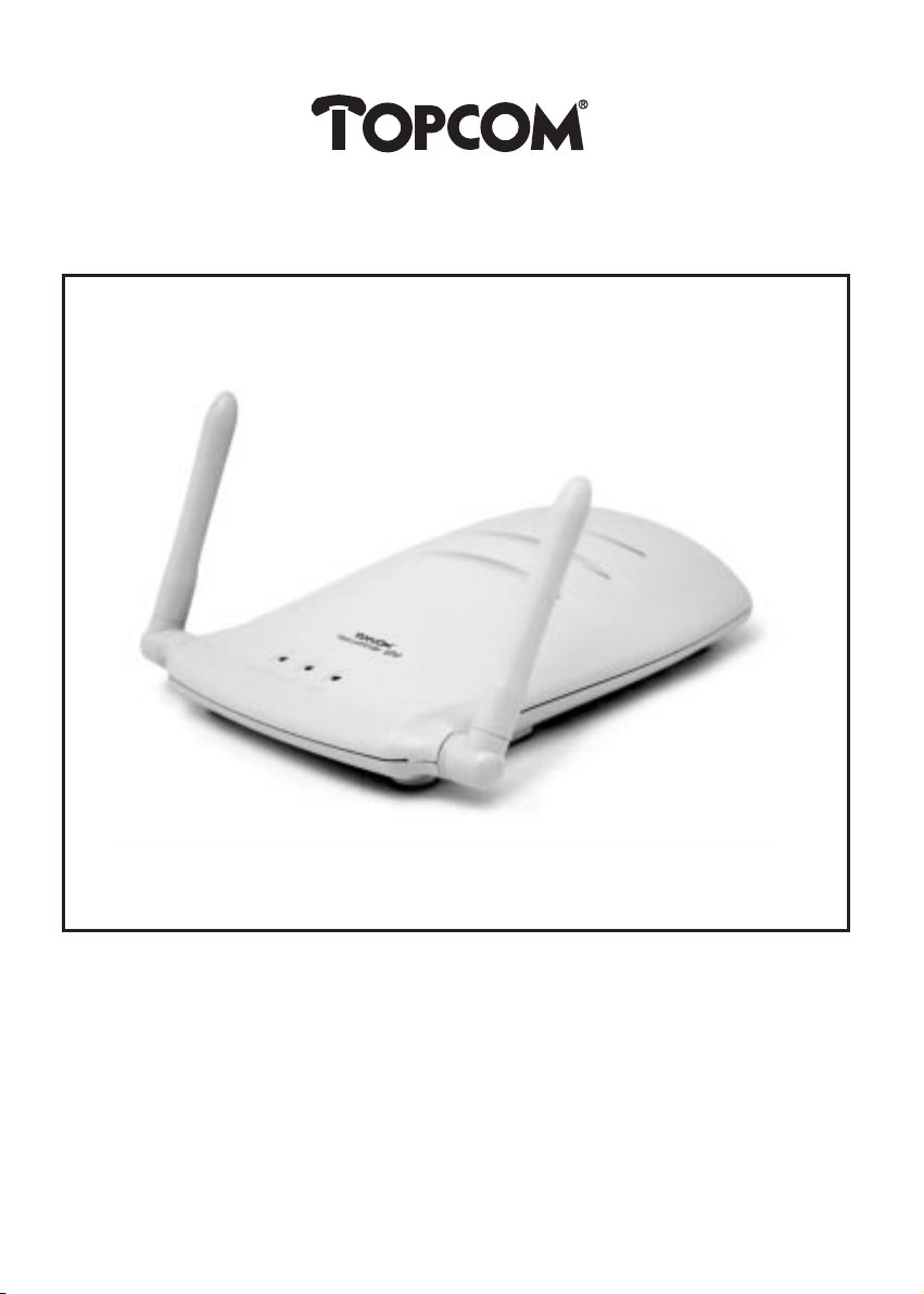
1. Open the Access Point Configuration Utility by selecting Start > Programs > IEEE 802.11 Access
Point > Access Point Configuration Utility. The Connect to Access Point window opens automatically. In this window, you can see the Access Point(s) in the Available Access Points column.
2. Double-click the target Access Point which you want to configure, then the Change Access Point’s
IP Address window pops up.
SkyLanR@cer 500
5
ENGLISH
55
Page 6
3. Type the New IP Address which is suitable for the communication between the Access Point and
the PC which executes the Access Point Configuration Utility. Then click the OK button.
4. A warning message appears that “You must use ‘Download Changes’ to change your IP address
permanently”, just click OK.
5. You will return to the Connect to Access Point window. In the Available Access Points column,
double-click the target Access Point whose IP address you just modified. In the Community field,
type the Administrator community name: admin. Then click the Connect button.
6. After connection is established, select File > Download Changes. When “Do you want to
Download Configuration? ”message appears, click Yes . When download is finished, you’ll see
“Download configuration done” message on the status bar. Now you have assigned a permanent
IP address to this Access Point.
Connecting to the Access Point
1. Launch the Access Point Configuration Utility.
2. Within the utility appears the Connect to Access Point window. In the Available Access Points
column, double-click the target Access Point which you want to configure.
3. In the Community field, type the Administrator community name admin and then click the
Connect button.
Note: If you are connecting to the Access Point using User Community name public, only read-only access is allowed. Some of the menu options are not available. Download Changes are not allowed either.
SkyLanR@cer 500
6
Page 7

When the connection has been successfully established, the left side of the status bar shows the message “Get Configuration Done” while the right side appears the IP Address of the connected Access
Point. At the same time, the Access Point Settings window pops up within the utility window.
From now on, you can start to customise the Access Point settings as described in next section.
Configuring the Access Point
Access Point Setting
Access Point settings window always opens automatically when you connect to the target Access
Point. This window allows you to make the basic settings for proper operation. Enter the required
values for the parameters below:
Access Point Name: The name used for identifying the Access Point.
ESSID (Extended Service Set Identity): The name used for identifying the WLAN.
Channel::The radio frequency used for communication. Select a channel out of the available channels
or used the default channel.
Dynamic/Static IP Settings: Select whether to use Dynamic IP or Static IP as required by your network requirements. If you want to enable the Dynamic IP Address (DHCP Client Enable) option,
select whether to use the DHCP Server in Ethernet or Wireless, which is the interface that determines the DHCP server.
Note: After setup, click OK and then select File > Download Changes to save changes. When “Do you want to
Download Configuration?” message appears, click Yes . When download is finished, you’ll see “Download configuration done” message on the status bar.
SkyLanR@cer 500
7
ENGLISH
Page 8
SkyLanR@cer 500
8
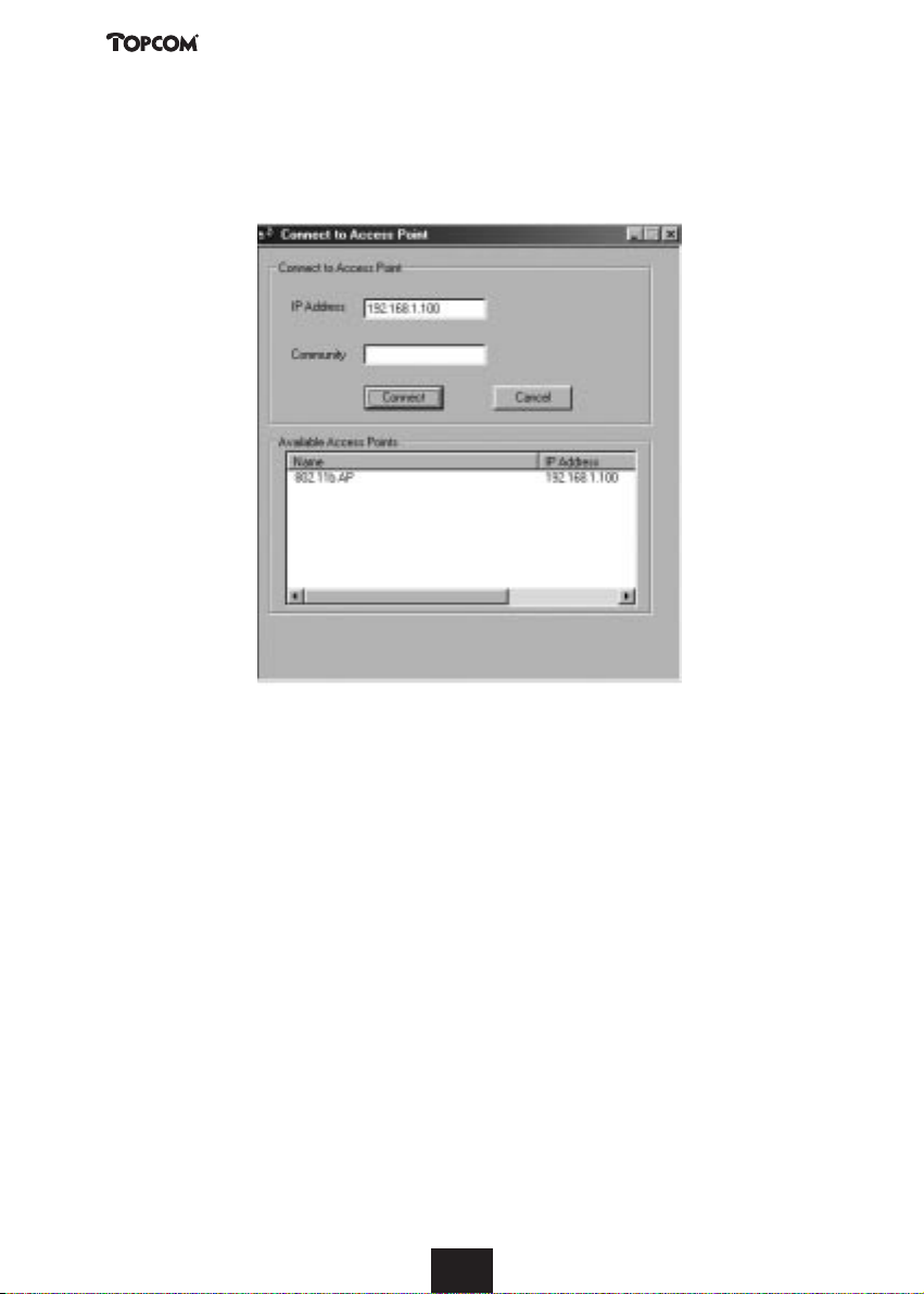
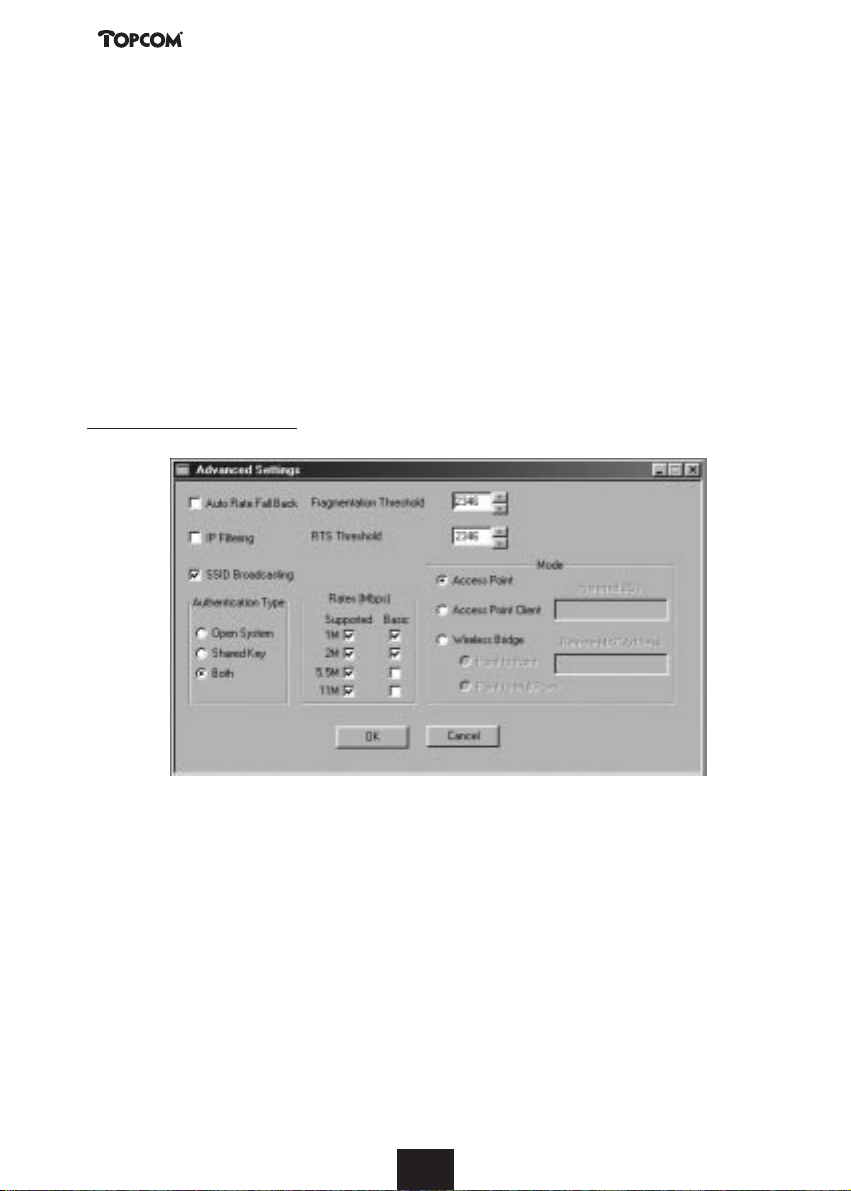
Advanced Settings
Advance Settings allow you to set up advanced parameters described as follows:
Auto Rate Fall Back: If enabled, the Access Point will automatically adjust the transfer speed for best
performance and greatest range.
IP Filtering: If enabled, only the IP protocol packets will pass through the WLAN and any other protocol will be filtered out.
SSID Broadcasting: If enabled, the Wireless Station with ESSID set to “any” can connect to this
Access Point. If this option is disabled, this Access Point just only accept stations whose ESSID are the
same as this Access Point connection.
Fragmentation Threshold: The fragmentation threshold, which is specified in bytes, determines
whether packets will be fragmented and at what size. On an 802.11 wireless LAN, packets exceed the
fragmentation threshold are fragmented, i.e., split into, smaller units suitable for the circuit size.
Packets smaller than the specified fragmentation threshold value are not fragmented.
RTS (Request to Send) Threshold: When set (in bytes), it specifies the packet size beyond which the
Wireless LAN Card invokes its RTS/CTS mechanism. Packets that exceed the specified RTS threshold
trigger the RTS/CTS mechanism. The NIC transmits smaller packets without using RTS/CTS.
Authentication Type: Select the authentication type from Open System, Shared Key or Both. The
authentication type must be the same on the Access Point and the Wireless Stations to be able to
communicate.
Note: The Authentication type must be the same on the wireless client and on the Access Point. All shared keys on
the Wireless Station must be the same as those on the Access Point with which the client station is associated.
Rates (Mbps): If Auto Rate Fall Back option is enabled, the Access Point will automatically adjust
the transfer speed to the rates you checked as Supported. Basic means only the Wireless Stations
with rates you checked can connect to this Access Point.
Page 9

SkyLanR@cer 500
9
ENGLISH
Mode (Operation Mode): Select one operation mode according to your network requirements.
Access Point: This mode provides access from Wireless Stations to wired LANs and from wired LANs
to Wireless Stations. Furthermore, Wireless Stations within the range of the Access Point device may
communicate with each other via the Access Point.
Access Point Client: This mode allows the connection of one or more remote LANs with a central
LAN, creating thus an extended single virtual LAN. In this way, any Station from the remote LAN can
successfully communicate with any Station of the central LAN, as if all of them belonged to the same
physical LAN. Wireless Stations can't be associated with the Access Point Client. The Access Point conducts the designated traffic to the appropriate wired or Wireless Station. User needs to define the
Preferred BSS which corresponds to the MAC Address of the desired Access Point.
Wireless Bridge: This mode allows two types of connections:
I) Point to Point: The Wireless Bridge can communicate with a specific Remote MAC Address. User
needs to define the Remote MAC Address, which corresponds to the MAC address of the
Wireless Bridge of the Remote LAN.
Figure A Wireless Bridge environment
Page 10

II) Point to Multipoint: The Wireless Bridge can communicate with any Wireless Bridge available in
the same channel.
Figure B Building To Building environment
Note: After you made all the advanced settings as required, select File > Download Changes. When “Do you want
to Download Configuration?” message appears, click Yes . When download is finished, you’ll see “Download configuration done” message on the status bar.
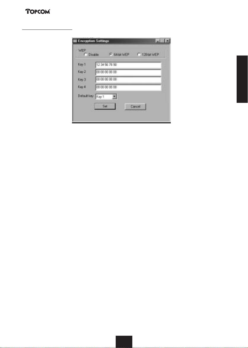
Encryption Settings
If you are going to enable WEP, select whether to use 64-bit WEP or 128-bit WEP as the encryption
algorithm. Then enter the WEP keys in Key 1-4 fields. WEP keys must be comprised of the hexadecimal characters (0-9, A-F, and a-f) and must contain 10 characters for 64-bit WEP Keys or 26 characters for 128-bit WEP keys.
SkyLanR@cer 500
10
Page 11
SkyLanR@cer 500
11
ENGLISH
In the Default Key field, select one of the four keys to encrypt the data before being transmitted. All
stations, including this Access Point, always transmit data encrypted using the Default Key. The key
number (1,2,3,4) is also transmitted. The receiving station will use the key number to determine which
key to use for decryption. If the key value does not match with the transmitting station, the decryption will fail. To ensure successful decryption, have your Wireless Stations set identical key tables.
Note: All Wireless Stations must use the same encryption algorithm and the same Key value (same key position in its
key table) as the Access Point.
After setup, click the Set button to enable the settings.
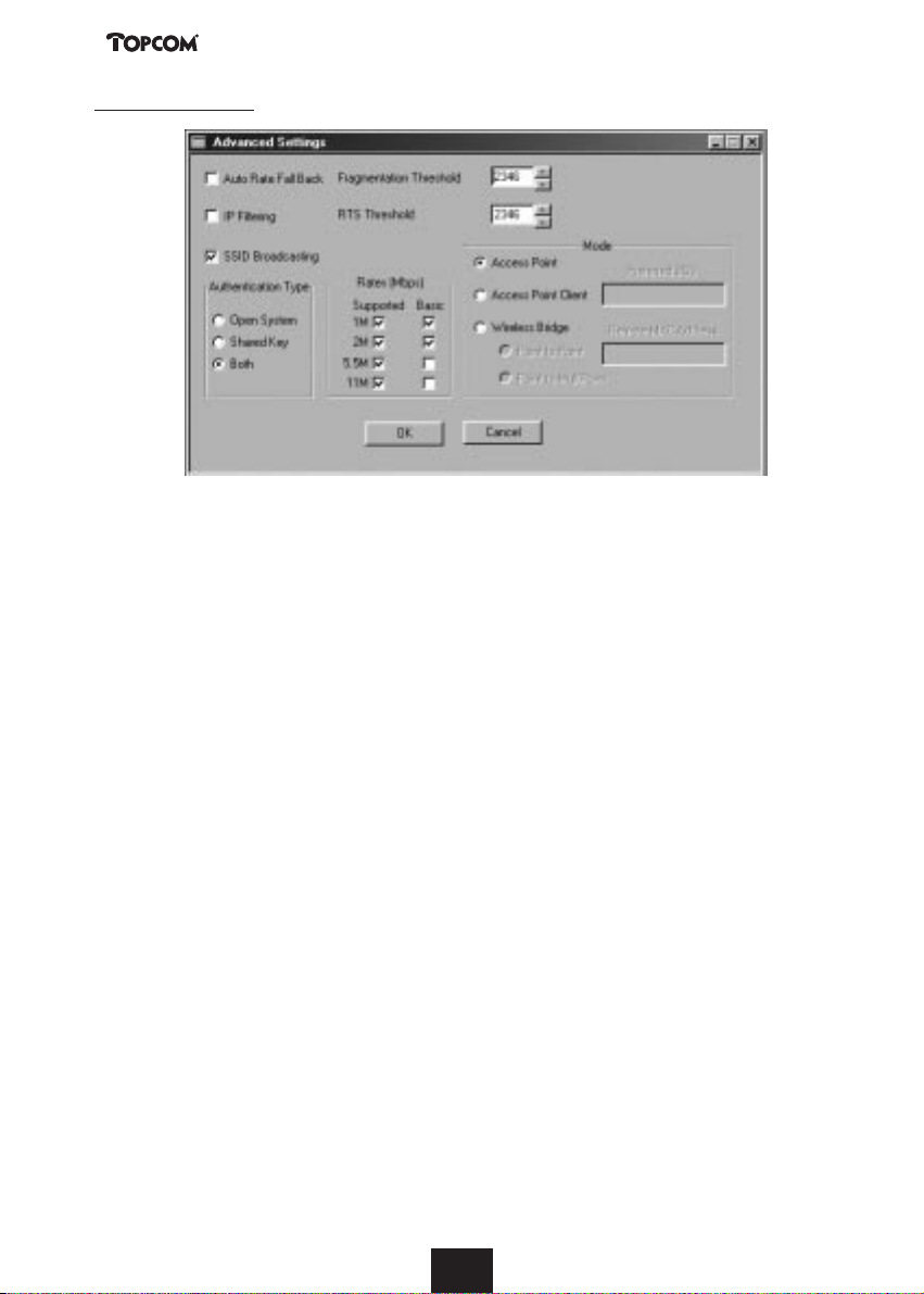
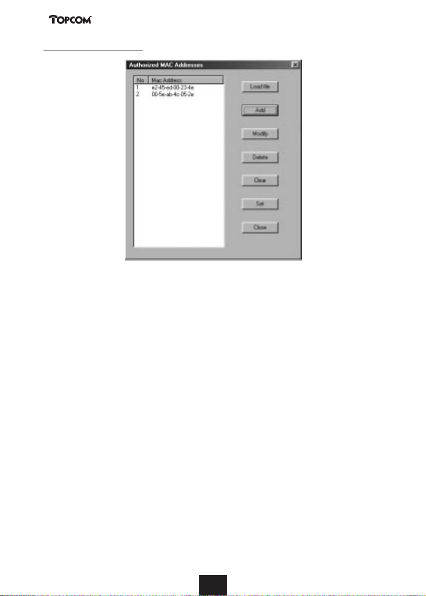
Authorised MAC Address
This panel allows you to view or edit the Authorised MAC Address list. You can determine which
client is authorised to associate with this Access Point by adding its MAC address to this Authorised
MAC Address list. If left to blank, all the Wireless Stations are capable of connecting to the network
via this Access Point.
The button of Add, Modify, Delete and Clear are used to edit the list. For your convenience, you
can pre-define the MAC addresses in a text file (*.txt) and click the Load File button to load these
addresses from this text file. To enable the settings, click the Set button. Clicking Set will prompt you
with the message: “Do you want to Download these Mac Addresses?”.
Click Ye s to start the download.
Page 12
SkyLanR@cer 500
12
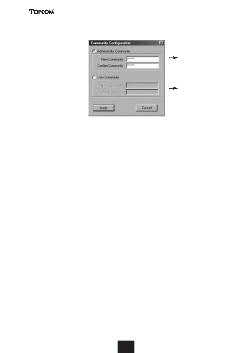
Community Configuration
default: admin
default: public
This option is used when the Administrator wishes to change the community name for
Administrator Community or the User Community. For each community, enter the new password
in the New Community filed and re-enter the value in Confirm Community field. Then click Apply
to enable changes. If successful, “Password changed” message will appear.
Note that both passwords are case-sensitive.
Enable Network Management Log
This option is used to enable or disable Network Management Log, which are messages displayed by
selecting Information >View Log Records. Log keeps a running records of the Access Point opera-
tion. The information provided are useful for Administrators when troubleshooting.
4. TOPCOM WARRANTY
4.1. Warranty period
The Topcom units have a 24-month warranty period. The warranty period starts on the day the new
unit is purchased by the consumer.
The warranty has to be proven by presentation of the original bill or receipt, on which the date of
purchase and the model of unit are indicated.
4.2. Warranty handling
A faulty unit needs to be returned to a Topcom service centre including a valid purchase note.
If the unit develops a fault during the warranty period, Topcom or its officially appointed service
centre will repair any defects caused by material or manufacturing faults free of charge.
Topcom will at its discretion fulfil its warranty obligations by either repairing or exchanging the faulty
units or parts of the faulty units.
The initial purchase date shall determine the start of the warranty period. The warranty period is not
extended if the unit is exchanged or repaired by Topcom or its appointed service centres.
Page 13

4.3. Warranty exclusions
Damage or defects caused by incorrect treatment or operation and damage resulting from use of nonoriginal parts or accessories not recommended by Topcom are not covered by the warranty.
The warranty does not cover damage caused by outside factors, such as lightning, water and fire, nor
any damage caused during transportation.
No warranty can be claimed if the serial number on the units has been changed, removed or rendered
illegible.
Any warranty claims will be invalid if the unit has been repaired, altered or modified by the buyer or
by unqualified, non-officially appointed Topcom service centres.
Technical Data
Frequency band: 2,4 GHz
Range: max. 300 m in open space
max. 50 m in buildings
Ambient temperature: +5 °C to +45 °C
Permitted relative air humidity: 25 to 85 %
Power supply base adapter: 100V ~ 240V AC (50 ~ 60 Hz)
SkyLanR@cer 500
13
ENGLISH
Page 14

SkyLanR@cer 500
14
Veiligheidsvoorschriften
• Gebruik enkel de meegeleverde adapter. Geen vreemde adapters gebruiken, het toestel kan
hierdoor beschadigd worden.
• Het toestel niet opstellen in vochtige ruimten en niet op minder dan 1,5 m van een waterbron.
• Het toestel niet gebruiken in explosieve omgevingen.
Reinigen
Veeg het toestel met een licht vochtig doek of met een antistatische doek af. Gebruik nooit
reinigingsmiddelen of agressieve oplosmiddelen.
1. DE HARDWARE VOOR DRAADLOZE TOEGANG INSTALLEREN 15
1.1. De voeding aansluiten 15
1.2. De ethernetaansluiting tot stand brengen 15
2. DE ACCESS POINT CONFIGURATION UTILITY INSTALLEREN 15
3. DE ACCESS POINT CONFIGURATION UTILITY GEBRUIKEN 15
4. DE GARANTIE VAN TOPCOM 24
4.1. Garantietermijn 24
4.2. Garantieprocedure 24
4.3. Garantiebeperkingen 24
Page 15

In deze Handleiding voor een snelle installatie worden enkel een aantal basisinstructies uiteengezet.
Voor gedetailleerdere informatie verwijzen we naar het bestand Handleiding op de meegeleverde CD.
1. DE HARDWARE VOOR DRAADLOZE TOEGANG
INSTALLEREN
1.1. De voeding aansluiten
Sluit de enige connector van de adapter aan op de gelijkstroomingang aan de achterkant van het toegangspunt. Sluit vervolgens de meegeleverde voedingskabel aan op de wisselstroomadapter en steek
het andere uiteinde in een stopcontact.
1.2. De ethernetaansluiting tot stand brengen
De ethernetconnector RJ-45 aan het toegangspunt laat toe om het toegangspunt aan te sluiten op
een ethernethub of een ethernetschakelaar die deel uitmaakt van uw kabelnetwerk. Sluit de ene kant
van de RJ-45-UTP-kabel aan op het toegangspunt en het andere uiteinde op een connector die voor
ethernet-PC wordt gebruikt.
Opmerking: Als u het toegangspunt rechtstreeks wilt aansluiten op de ethernetconnector van uw PC, moet u
gebruik maken van een gekruiste UTP-kabel in plaats van een rechte UTP-kabel.
2. DE ACCESS POINT CONFIGURATION UTILITY
INSTALLEREN
Plaats de Access Point Configuration Utility CD in uw CD-station. Voer Setup.exe uit in de map
Utility van de CD. Zodra u de verwelkomingsschermen ziet verschijnen, volgt u de instructies die er
worden gegeven. Klik telkens op Next om elke stap te voltooien.
Klik ten slotte op Finish om de installatie te beëindigen.
3. DE ACCESS POINT CONFIGURATION UTILITY GEBRUIKEN
Het IP-adres van het toegangspunt instellen
Zorg ervoor dat u eerst het IP-adres van het toegangspunt heeft ingesteld vooraleer u de Access Point
Configuration Utility gebruikt om het toegangspunt te configureren.
1. Open de Access Point Configuration Utility door Start > Programs > IEEE 802.11 Access Point >
Access Point Configuration Utility te selecteren. U krijgt automatisch het scherm Connect to
Access Point te zien. In dit venster ziet u de beschikbare toegangspunten in de kolom Available
Access Points.
2. Dubbelklik op het toegangspunt dat u wilt configureren. U krijgt nu het scherm Change Access
Point’s IP Address te zien.
SkyLanR@cer 500
15
NEDERLANDS
Page 16

3. Voer het nieuwe IP-adres in dat geschikt is voor de communicatie tussen het toegangspunt en de
PC waarop de Access Point Configuration Utility draait. Klik vervolgens op de knop OK.
4. U krijgt de waarschuwing "You must use ‘Download Changes’ to change your IP address permanently" te zien. Klik op OK.
5. U keert nu terug naar het venster Connect to Access Point. In de kolom Available Access Points
dubbelklikt u op het toegangspunt waarvan u zonet het IP-adres wijzigde. In het veld Community
voert u de community-naam van de beheerder in: admin. Klik vervolgens op de knop Connect.
6. Nadat de verbinding tot stand is gebracht, selecteert u File > Download Changes. Wanneer de
melding "Do you want to Download Configuration?" verschijnt, klikt u op Yes. Zodra het afhalen
is beëindigd, ziet u in de statusbalk de melding "Download configuration done" verschijnen. U
heeft nu een permanent IP-adres toegekend aan dit toegangspunt.
SkyLanR@cer 500
16
Page 17

SkyLanR@cer 500
17
NEDERLANDS
Een verbinding met het toegangspunt tot stand brengen
1. Start de Access Point Configuration Utility.
2. U krijgt nu het scherm Connect to Access Point te zien. In de kolom Available Access Points
dubbelklikt u op het toegangspunt dat u wilt configureren.
3. In het veld Community voert u de community-naam van de beheerder in (admin) en klikt u op de
knop Connect.
Opmerking: Als u een verbinding met het toegangspunt tot stand brengt met de user community-naam public,
krijgt u uitsluitend Enkel lezen-toegang (read-only access). Een aantal menu-opties zijn niet beschikbaar. Ook de
downloadparameters kunnen niet worden gewijzigd.
Als de verbinding met succes tot stand werd gebracht, ziet u in de linkerkant van de statusbalk de
melding “Get Configuration Done”. Rechts in de statusbalk verschijnt het IP-adres van het aangesloten toegangspunt. Tegelijk verschijnt het venster Access Point settings in het scherm van de utility.
U kunt nu beginnen met het personaliseren van de instellingen van het toegangspunt. Dat wordt
beschreven in het volgende gedeelte.
Het toegangspunt configureren
Instelling van het toegangspunt
Het venster Access Point settings verschijnt telkens automatisch als u een verbinding tot stand
brengt met het gewenste toegangspunt. In dit venster kunt u de basisinstellingen uitvoeren voor een
correcte werking. Voer de gewenste waarden in voor de onderstaande parameters:
Page 18
Access Point Name: de naam die wordt gebruikt voor het identificeren van het toegangspunt.
ESSID (Extended Service Set Identity): de naam die wordt gebruikt voor het identificeren van de
WLAN.
Channel: de radiofrequentie die wordt gebruikt voor de communicatie. Selecteer een kanaal uit de
beschikbare kanalen of gebruik het standaardkanaal.
Dynamic/Static IP Settings: selecteer Dynamic IP of Static IP al naargelang uw netwerkvereisten.
Als u de optie Dynamic IP Address (DHCP Client Enable) wilt activeren, selecteer dan of u de
DHCP Server in Ethernet of Wireless wilt gebruiken. Dat is de interface voor de DHCP-server.
Opmerking: na het instellen klikt u op OK en selecteert u File > Download Changes om de wijzigingen op te
slaan. Als de melding "Do you want to Download Configuration?" verschijnt, klikt u op Yes . Zodra het afhalen is
beëindigd, ziet u in de statusbalk de melding "Download configuration done" verschijnen.
Geavanceerde instellingen
Met Advanced Settings kunt u geavanceerde instellingen uitvoeren, en wel als volgt:
Auto Rate Fall Back: als deze functie werd geactiveerd, zal het toegangspunt automatisch de beste
transmissiesnelheid kiezen voor optimale prestaties en het grootste bereik.
IP Filtering: als deze functie werd geactiveerd, zullen enkel pakketjes die met het IP-protocol worden
verzonden, via het WLAN mogen passeren. Daarbij worden alle andere protocols weggefilterd.
SSID Broadcasting: als deze functie werd geactiveerd, zal het draadloze station waarvan de ESSIDparameter op "any" werd ingesteld, een verbinding met dit toegangspunt tot stand kunnen brengen.
Als deze optie niet is geactiveerd, accepteert dit toegangspunt enkel stations waarvan de ESSIDparameter dezelfde is als die van deze toegangspuntverbinding.
Fragmentation Threshold: de fragmentatielimiet wordt uitgedrukt in bytes en bepaalt of pakketjes
worden gefragmenteerd en hoe groot deze pakketjes zijn. Bij een draadloos LAN-netwerk van het
SkyLanR@cer 500
18
Page 19

type 802.11 worden alle pakketjes gefragmenteerd die de fragmentatielimiet overschrijden. Dit betekent dat ze in kleinere eenheden worden opgesplitst die geschikt zijn voor het circuit. Pakketjes die
kleiner zijn dan de gespecificeerde grenswaarde worden niet gefragmenteerd.
RTS (Request to Send) Threshold: indien ingesteld (in bytes) wordt hiermee de pakketgrootte
gespecificeerd waarboven de draadloze LAN-kaart het RTS/CTS-mechanisme activeert. Pakketjes die
groter zijn dan de gespecificeerde RTS-grenswaarde activeren het RTS/CTS-mechanisme. De NIC verzendt kleinere pakketjes zonder gebruik te maken van RTS/CTS.
Authentication Type: selecteer het authentificatietype: Open System, Shared Key of Both. Opdat
communicatie mogelijk zou zijn, moet het authentificatietype van het toegangspunt en van de draadloze stations hetzelfde zijn.
Opmerking: het authentificatietype van de draadloze client moet hetzelfde zijn als dat van het toegangspunt. Alle
gedeelde sleutels op het draadloze station moeten dezelfde zijn als die van het toegangspunt waaraan de client is
gekoppeld.
Rates (Mbps): als de optie Auto Rate Fall Back werd geactiveerd, zal het toegangspunt automatisch
de transmissiesnelheid aanpassen aan de waarden die u als Supported (ondersteund) heeft gekenmerkt. Basic betekent dat enkel de draadloze stations met de door u geselecteerde snelheden een
verbinding tot stand kunnen brengen met dit toegangspunt.
Mode (Operation Mode): selecteer een enkele werkmodus al naargelang uw netwerkvereisten.
Access Point: deze modus maakt het mogelijk om toegang te verkrijgen van draadloze stations tot
bedrade LAN's en van bedrade LAN's tot draadloze stations. Bovendien kunnen draadloze stations
binnen het bereik van het toegangspunt met elkaar communiceren via het toegangspunt.
Access Point Client: deze modus maakt het mogelijk om een of meer afgelegen LAN's te verbinden
met een centrale LAN, zodat een uitgebreide, enkelvoudige, virtuele LAN ontstaat. Op deze manier
kan elk station van de afgelegen LAN met succes communiceren met elk station van de centrale LAN
alsof al deze stations tot dezelfde fysieke LAN behoorden. Draadloze stations kunnen niet worden
aangemeld op de toegangspuntclient. Het toegangspunt stuurt het betreffende verkeer door naar het
geschikte bedrade of draadloze station. De gebruiker moet de Preferred BSS definiëren die overeenkomt met het MAC-adres van het gewenste toegangspunt.
Wireless Bridge: in deze modus zijn twee types verbindingen mogelijk:
I) Point to Point: de draadloze brug kan communiceren met een specifiek afgelegen MAC-adres. De
gebruiker moet het Remote MAC Address definiëren dat overeenstemt met het MAC-adres van
de draadloze brug van de afgelegen LAN.
SkyLanR@cer 500
19
NEDERLANDS
Page 20

Figuur A: draadloze brug en omgeving
II) Point to Multipoint: de draadloze brug kan communiceren met alle draadloze bruggen die
beschikbaar zijn op hetzelfde kanaal.
Figuur B: van gebouw naar gebouw
Opmerking: nadat u alle noodzakelijke geavanceerde instellingen heeft uitgevoerd, selecteert u File > Download
Changes. Als de melding "Do you want to Download Configuration?" verschijnt, klikt u op Yes . Zodra het afhalen is
beëindigd, ziet u in de statusbalk de melding "Download configuration done" verschijnen.
SkyLanR@cer 500
20
Page 21
Encryptie-instellingen
Als u WEP gaat activeren, moeten u selecteren of u 64-bit WEP of 128-bit WEP wilt gebruiken als
encryptiealgoritme. Voer vervolgens in de velden Key 1-4 de WEP-sleutels in. WEP-sleutels moeten
samengesteld zijn uit hexadecimale tekens (0-9, A-F en a-f). WEP-sleutels van 64 bits moeten 10
tekens hebben, WEP-sleutels van 128 bit moeten 26 tekens bevatten.
In het vak Default Key selecteert u één van de vier sleutels waarmee u de gegevens wilt coderen
voor verzending. Alle stations, met inbegrip van dit toegangspunt, verzenden gegevens steeds in
gecodeerde vorm waarbij de encryptie plaatsvindt met de standaardsleutel. Ook het sleutelnummer
(1,2,3,4) wordt verzonden. Het ontvangende station zal het sleutelnummer gebruiken om te bepalen
welke sleutel moet worden gebruikt bij het decoderen. Als het sleutelnummer niet overeenstemt met
dat van het zendende station zal het decoderen mislukken. Voor een succesvolle decodering moet u
identieke sleuteltabellen instellen op uw draadloze stations.
Opmerking: alle draadloze stations moeten hetzelfde encryptiealgoritme gebruiken en dezelfde sleutelwaarde (en
bijgevolg dezelfde sleutelpositie in de sleuteltabel) als het toegangspunt.
Na het instellen klikt u op de knop Set om de instellingen te activeren.
SkyLanR@cer 500
21
NEDERLANDS
Page 22
Authorised MAC Address
Dit overzicht biedt u de mogelijkheid om de lijst van toegelaten MAC-adressen te bekijken of te wijzigen. U kunt zelf bepalen welke client zich mag aanmelden bij dit toegangspunt door het MAC-adres
van de client toe te voegen aan deze Authorised MAC Address List. Als dit overzicht blanco wordt
gelaten, zullen alle draadloze stations verbinding kunnen maken met het netwerk via dit toegangspunt.
Om de lijst te editeren, gebruikt u de knoppen Add, Modify, Delete en Clear. Om een en ander te
vereenvoudigen, kunt u MAC-adressen vastleggen in een tekstbestand (*.txt). Klik in dat geval op de
knop Load File om de adressen in het bestand uit te lezen. Om de instellingen te activeren klikt u op
de knop Set. Daarbij komt de volgende melding op het scherm: “Do you want to Download these
Mac Addresses?”.
Klik op Yes om het afhalen te starten.
SkyLanR@cer 500
22
Page 23

Community-configuratie
standaard: admin
standaard: public
Deze optie wordt gebruikt als de beheerder de community-naam wenst te wijzigen voor de
Administrator Community of voor de User Community. Voor elke community typt u het nieuwe
paswoord in het veld New Community en typt u het paswoord nogmaals in het veld Confirm
Community. Klik vervolgens op Apply om de wijzigingen te bevestigen. Als de wijzigingen werden
aanvaard, krijgt u de melding “Password changed” te zien.
Zorg ervoor dat u bij de twee paswoorden hoofd- en kleine letters correct invoert.
Network Management Log activeren
Deze optie wordt gebruikt om het Network Management Log in- of uit te schakelen. Deze berichten
kunt u bekijken door Information > View Log Records te selecteren. In het logbestand wordt informatie opgeslagen over de werking van het toegangspunt. Die informatie kan nuttig zijn voor systeembeheerders bij het oplossen van problemen.
SkyLanR@cer 500
23
NEDERLANDS
Page 24

4. DE GARANTIE VAN TOPCOM
4.1. Garantietermijn
Voor de toestellen van Topcom geldt een garantieperiode van 24 maanden. De garantieperiode start
op de dag waarop het nieuwe toestel wordt aangekocht door de gebruiker.
De garantie moet worden aangetoond door voorlegging van de originele factuur of het originele
kasticket, waarop de datum van aankoop en het toesteltype moet worden vermeld.
4.2. Garantieprocedure
Het defecte toestel moet naar een Topcom-servicedienst worden gebracht, samen met een geldig
aankoopbewijs.
Als het toestel defect raakt tijdens de garantieperiode, zullen Topcom of een officieel aangestelde
servicedienst van Topcom het toestel kostenloos herstellen als het materiaaldefecten of
productiefouten betreft.
Topcom zal naar eigen goeddunken zijn garantieverplichtingen nakomen door defecte toestellen te
herstellen of te vervangen of door onderdelen van het defecte toestel te herstellen of te vervangen.
De eerste datum van aankoop bepaalt het tijdstip waarop de garantie een aanvang neemt. De
garantieperiode wordt niet verlengd als het toestel wordt vervangen of hersteld door Topcom of een
door Topcom aangeduid servicecentrum.
4.3. Garantiebeperkingen
De garantie is niet van toepassing bij schade of defecten die veroorzaakt worden door een onjuiste
behandeling of verkeerde handelingen of door het gebruik of schade als gevolg van het gebruik van
niet-originele onderdelen of accessoires die niet door Topcom worden aangevolen.
De garantie geldt niet voor schade die door externe factoren wordt veroorzaakt, zoals bliksem, water
en vuur, en evenmin voor transportschade.
De garantie vervalt wanneer het serienummer op het toestel werd gewijzigd, verwijderd of onleesbaar
gemaakt.
De garantie vervalt wanneer het toestel wordt hersteld, gewijzigd of aangepast door de koper of door
servicecentra die niet officieel door Topcom zijn erkend.
SkyLanR@cer 500
24
Page 25

Technische gegevens
Frequentieband: 2,4 GHz
Reikwijdte: max. 300 m in open ruimte
max. 50 m in gebouwen
Omgevingstemperatuur: +5 °C tot +45 °C
Toegelaten relatieve luchtvochtigheid: 25 tot 85 %
Netspanning adapter basisstation: 100V ~ 240V AC (50 ~ 60 Hz)
SkyLanR@cer 500
25
NEDERLANDS
Page 26

1. INSTALLATION DU MATÉRIEL DU POINT D’ACCÈS SANS FIL 27
1.1. Branchement de l’alimentation 27
1.2. Etablissement de la Connexion Ethernet 27
2. INSTALLATION DE L’UTILITAIRE DE CONFIGURATION DU POINT D’ACCÈS 27
3. UTILISATION DE L’UTILITAIRE DE CONFIGURATION DU POINT D’ACCÈS 27
4. GARANTIE DE TOPCOM 36
4.1. Période de garantie 36
4.2. Traitement de la garantie 36
4.3. Exclusions de garantie 36
SkyLanR@cer 500
26
Consignes de sécurité
• Utilisez uniquement l’adaptateur fourni à la livraison. Ne pas utiliser des adaptateurs étrangers,
l’appareil pourra être endommagé.
• Ne pas placer l’appareil dans une pièce humide ou à moins de 1,5 m d'un point d'eau.
• N'utilisez pas l’appareil dans un endroit où une explosion est susceptible de se produire.
Entretien
Frottez l’appareil avec un chiffon légèrement humide ou avec un linge antistatique. N'utilisez
jamais de produits détergents ou agressifs.
Page 27

SkyLanR@cer 500
27
FRANÇAIS
27
Le présent Guide d’Installation Rapide vous donne seulement les instructions de base. Pour des informations plus détaillées, vous êtes prié de vous reporter au fichier Manual (Manuel) qui se trouve sur le
CD fourni.
1. INSTALLATION DU MATÉRIEL DU POINT D’ACCÈS
SANS FIL
1.1. Branchement de l’alimentation
Raccordez l’unique connecteur de sortie DC de l’adaptateur d’alimentation à la prise d’alimentation
DC se trouvant sur la face arrière du Point d’Accès. Raccordez ensuite une extrémité du cordon d’alimentation fourni à l’adaptateur d’alimentation AC et enfichez son autre extrémité dans une prise du
réseau AC.
1.2. Etablissement de la Connexion Ethernet
Le jack de connexion RJ-45 Ethernet du Point d’Accès sert à raccorder le Point d’Accès à un
Commutateur/Concentrateur Ethernet qui fait partie de votre réseau câblé. Connectez une extrémité
du câble RJ-45 UTP (torsadé non blindé) au Point d’Accès et son autre extrémité à tout jack du concentrateur qui ressemble à ceux utilisés pour PC Ethernet.
Note: Si vous souhaitez connecter le Point d’Accès directement au jack Ethernet de votre PC, un câble UTP croisé
sera utilisé en lieu et place d’un câble UTP (torsadé non blindé) droit.
2. INSTALLATION DE L’UTILITAIRE DE CONFIGURATION DU
POINT D’ACCÈS
Insérez le CD de l’Utilitaire de Configuration du Point d’Accès dans le CD-ROM. Exécutez Setup.exe
du dossier Utility (Utilitaire) du CD fourni. Lorsque l’écran d’accueil apparaît, suivez les instructions
données sur cet écran pour continuer. Cliquez sur Next (Prochain) après que chaque étape a été
effectuée.
Finalement, cliquez sur Finish (Finir) pour terminer l’installation.
3. UTILISATION DE L’UTILITAIRE DE CONFIGURATION DU
POINT D’ACCÈS
Définition de l’Adresse IP du Point d’Accès
Avant d’utiliser l’Utilitaire de Configuration du Point d’Accès, vérifiez que l’adresse IP du Point d’Accès
a bien été paramétrée.
1. Ouvrez l’Utilitaire de Configuration du Point d’Accès en sélectionnant Start (Démarrer) >
Programs (Programmes) > IEEE 802.11 Access Point (Point d’Accès IEEE 803.11) > Access
Point Configuration Utility (Utilitaire de Configuration du Point d’Accès). La fenêtre
Connect to Access Point (Se Connecter au Point d’Accès) s’ouvre automatiquement. Dans cette
fenêtre, vous pouvez voir le(s) Point(s) d’Accès dans la colonne Available Access Points (Points
d’Accès Disponibles).
Page 28

2. Double-cliquez sur le Point d’Accès cible que vous désirez configurer, et la fenêtre Change Access
Point’s IP Address (Changer l’Adresse IP du Point d’Accès) apparaît alors.
3. Tapez la New IP Address (Nouvelle Adresse IP) qui convient à la communication entre le Point
d’Accès et le PC qui exécute l’Utilitaire de Configuration du Point d’Accès. Cliquez ensuite sur le
bouton OK.
4. Un message d’avertissement apparaît qui vous annonce “You must use ‘Download Changes’ to
change your IP address permanently” (“Vous devez utiliser ‘Download Changes’ (‘Télécharger les
Modifications‘) pour modifier votre adresse IP de manière permanente”) ; cliquez alors simplement
sur OK.
5. Vous allez retourner à la fenêtre Connect to Access Point (Se Connecter au Point d’Accès). Dans
la colonne Available Access Points (Points d’Accès Disponibles), double-cliquez sur le Point
d’Accès cible dont vous venez de modifier l’adresse IP. Dans le champ Community (Communauté),
tapez le nom de communauté de l’Administrateur: admin. Cliquez ensuite sur le bouton Connect
(Connecter).
SkyLanR@cer 500
2828
Page 29

6. Après que la connexion a été établie, sélectionnez File (Fichier) > Download Changes (Télécharger
les Modifications). Lorsque le message “Do you want to Download Configuration? (Désirez-vous
Télécharger la Configuration? ” apparaît, cliquez sur Yes (Oui). Lorsque le téléchargement est terminé, vous verrez le message “Download configuration done (Téléchargement Configuration exécuté)” sur la barre d’état. Vous avez maintenant affecté une adresse IP permanente à ce Point
d’Accès.
Connexion au Point d’Accès
1. Lancez l’Utilitaire de Configuration du Point d’Accès.
2. Dans l’utilitaire apparaît la fenêtre Connect to Access Point (Connecter au Point d’Accès). Dans la
colonne Available Access Points (Points d’Accès Disponibles), double-cliquez sur le Point d’Accès
cible que vous désirez configurer.
3. Dans le champ Community (Communauté), tapez le nom de communauté de l’Administrateur
admin et cliquez ensuite sur le bouton Connect (Connecter).
Note: Si vous êtres en train de vous occuper de la connexion au Point d’Accès qui utilise public comme nom de
Communauté Utilisateur, seul l’accès ‘lecture seule’ est autorisé. Certaines options du menu ne sont pas disponibles.
La téléchargement des modifications n’est pas permis non plus.
Lorsque la connexion a été établie avec succès, le côté gauche de la barre d’état affiche le message
“Get Configuration Done (Acquisition Configuration exécutée”) tandis qu’apparaît sur le côté droit la
IP Address (Adresse IP) du Point d’Accès connecté. Au même moment, la fenêtre Access Point set-
tings (Réglages du Point d’Accès) apparaît dans la fenêtre d’utilitaire.
A partir de maintenant, vous pouvez commencer à personnaliser les réglages du Point d’Accès comme
décrit dans la section qui suit.
Configuration du Point d’Accès
Réglages du Point d’Accès
SkyLanR@cer 500
29
FRANÇAIS
29
Page 30

SkyLanR@cer 500
3030
La fenêtre Access Point settings (Réglages du Point d’Accès) s’ouvre toujours automatiquement lorsque vous vous connectez au Point d’Accès cible. Cette fenêtre vous permet de procéder aux réglages
de base pour obtenir un fonctionnement correct. Entrez les valeurs requises pour les paramètres cidessous:
Access Point Name (Nom du Point d’Accès): Le nom utilisé pour identifier le Point d’Accès.
ESSID (Extended Service Set Identity (Identité Jeu Services Etendus): Le nom utilisé pour identifier le
WLAN.
Channel (Canal): La fréquence radio utilisée pour la communication. Sélectionnez un canal parmi les
canaux disponibles ou used utilisez le canal par défaut.
Dynamic/Static IP Settings (Réglages IP Dynamiques/Statiques): Sélectionnez ce qu’il faut utiliser:
Dynamic IP (IP Dynamique) ou Static IP (IP Statique) en fonction des exigences de votre réseau. Si
vous désirez activer l’option Dynamic IP Address (DHCP Client Enable) (Adresse IP Dynamique
(Activer Client DHCP), sélectionnez DHCP Server in Ethernet (Serveur DHCP d’Ethernet) ou Wireless
(Sans Fil) pour définir ce que vous comptez utiliser en tant qu’interface qui détermine le serveur DHCP.
Note: Après le paramétrage, cliquez sur OK et sélectionnez alors File (Fichier) > Download Changes
(Télécharger Modifications) pour sauvegarder les modifications. Lorsque le message “Do you want to
Download Configuration? (Désirez-vous Télécharger la Configuration)” apparaît, cliquez sur Yes (Oui).
Lorsque le téléchargement est terminé, vous verrez apparaître le message “Download configuration
done (Téléchargement de la configuration effectué)” sur la barre d’état.
Réglages Evolués
Advance Settings (Réglages Evolués) vous permet d’installer les paramètres évolués dont la liste suit:
Auto Rate Fall Back (Repli Débit Auto): Si activé, le Point d’Accès va automatiquement sélectionner
la vitesse de transfert qui permet d’obtenir les meilleures performances et la plus large plage.
IP Filtering (Filtrage IP): Si activé, seuls les paquets de protocole IP passeront au travers du WLAN et
tout autre protocole sera bloqué par filtrage.
Page 31

SSID Broadcasting (Diffusion SSID): Si activé, la Station Sans Fil avec ESSID définie comme “any”
(“n’importe laquelle”) peut se connecter à ce Point d’Accès. Si cette option est désactivée, ce Point
d’Accès accepte uniquement les stations dont les ESSID sont les mêmes que pour cette connexion au
Point d’Accès.
Fragmentation Threshold (Seuil de Fragmentation): Le seuil de fragmentation, qui est spécifié en
octets, détermine si les paquets vont être fragmentés et sous quelle dimension. Sur un LAN sans fil
802.11, les paquets qui dépassent le seuil de fragmentation sont fragmentés, c’est-à-dire qu’ils vont
être divisés en plus petites unités convenant mieux aux capacités du circuit. Les paquets inférieurs au
seuil de fragmentation spécifié ne seront pas fragmentés.
RTS (Request to Send) Threshold (Seuil RTS (Demande d’Emettre)): Lorsque défini (en octets),
bytes), il spécifie la dimension de paquet au-delà de laquelle la Carte LAN Sans Fil appelle son mécanisme RTS/CTS. Les paquets qui dépassent le seuil RTS spécifié déclenchent le mécanisme RTS/CTS. Le
NIC émet alors de plus petits paquets sans utiliser RTS/CTS.
Authentication Type (Type d’Authentification): Sélectionnez le type d’authentification parmi Open
System (Système Ouvert), Shared Key (Clé Partagée) ou Both (les deux). Le type d’authentification doit
être le même au Point d’Accès qu’aux Stations Sans Fil afin qu’une communication soit possible.
Note: Le type d’Authentification doit être le même chez le client sans fil et au Point d’Accès. Toutes les clés partagées à la Station Sans Fil doivent être les mêmes que celles du Point d’Accès avec lequel le client est en liaison.
Rates (Mbps) (Débits (Mbps)): Si l’option Auto Rate Fall Back (Repli Débit Auto) est activée, le Point
d’Accès réglera automatiquement la vitesse de transfert aux débits que vous avez cochés comme
Supported (Supportés). Basic (de Base) signifie que seules les Stations Sans Fil dont les débits sont
ceux que vous avez cochés pourront se connecter à ce Point d’Accès.
Mode (Operation Mode) (Mode de Fonctionnement): Sélectionnez un mode de fonctionnement en
fonction des exigences de votre réseau.
Access Point (Point d’Accès): Ce mode donne accès aux Stations Sans Fil vers les LAN câblés et aux
LAN câblés vers les Stations Sans Fil. En outre, les Stations Sans Fil se trouvant dans la zone de portée
du dispositif de Point d’Accès peuvent communiquer entre elles via le Point d’Accès.
Access Point Client (Client de Point d’Accès): Ce mode permet la connexion d’un ou plusieurs LAN
distant(s) à un LAN central, créant de la sorte un LAN virtuel individuel étendu. De cette manière,
toute Station du LAN distant peut communiquer de façon satisfaisante avec n’importe quelle Station
du LAN central, comme si chacune d’entre elles appartenait au même LAN physique. Les Stations Sans
Fil ne peuvent être reliées au Client de Point d’Accès. Le Point d’Accès dirige le trafic désigné vers la
Station Sans Fil ou câblée appropriée. L’utilisateur doit définir le Preferred BSS (BSS Préféré) qui correspond à l’Adresse MAC du Point d’Accès voulu.
Wireless Bridge (Pont Sans Fil): Ce mode permet deux types de connexions:
I) Point to Point (Point à Point): Le Pont Sans Fil peut communiquer avec une Adresse MAC distante
spécifique. L’utilisateur doit définir la Remote MAC Address (Adresse MAC distante) qui correspond à l’adresse MAC du Pont Sans Fil du LAN Distant.
SkyLanR@cer 500
31
FRANÇAIS
31
Page 32

SkyLanR@cer 500
3232
Figure A Environnement Pont Sans Fil
II) Point to Multipoint (Point à Multipoint): Le Pont Sans Fil peut communiquer avec tout Pont Sans
Fil disponible sur le même canal.
Figure B Environnement Bâtiment à Bâtiment
Note: Après avoir procédé à tous les réglages évolués nécessaires, sélectionnez File (Dossier) > Download Changes
(Télécharger les Modifications). Lorsque le message “Do you want to Download Configuration? (Désirez-vous
Télécharger la Configuration?)” apparaît, cliquez sur Yes (Oui). Lorsque le téléchargement est terminé, vous verrez
sur la barre d’état le message “Download configuration done (Téléchargement de la Configuration effectué)”.
Page 33

Réglages du Cryptage
Si vous allez activer WEP, sélectionnez l’algorithme de cryptage que vous désirez utiliser : 64-bit WEP
ou 128-bit WEP. Entrez alors les clés WEP dans les champs Key 1-4 (Clé 1-4). Les clés WEP doivent
être composées des caractères hexadécimaux (0-9, A-F, et a-f) et doivent comporter 10 caractères
pour les clés 64-bit ou 26 caractères pour les clés 128-bit.
Dans le champ Default Key (Clé par Défaut), sélectionnez une des quatre clés pour crypter les données avant qu’elles ne soient envoyées. Toutes les stations, le Point d’Accès compris, transmettent toujours des données cryptées en utilisant la Clé par Défaut. Le numéro de clé (1, 2, 3 ou 4) est également transmis. La station réceptrice utilisera le numéro de clé pour déterminer quelle clé doit être utilisée pour procéder au décryptage. Si la valeur de la clé ne correspond pas à celle de la station émettrice, le décryptage échouera. Afin d’assurer un décryptage couronné de succès, veillez à ce que vos
Stations Sans Fil soient définies avec des tables de clés identiques.
Note: Toutes les Stations Sans Fil doivent utiliser le même algorithme de cryptage et la même valeur de Clé (même
position de clé dans sa table de clé) que le Point d’Accès.
Après le paramétrage, cliquez sur le bouton Set (Définir) pour activer les réglages.
SkyLanR@cer 500
33
FRANÇAIS
33
Page 34

Adresses MAC Autorisées
Cet écran vous permet de voir ou d’éditer la liste d’adresses MAC autorisées. Vous pouvez déterminer
quel client est autorisé à être en liaison avec ce Point d’Accès en incorporant son adresse MAC dans
cette liste de Authorised MAC Address (Adresses MAC Autorisées). Si cette liste est laissée vide,
toutes les Stations Sans Fil peuvent se connecter au réseau via ce Point d’Accès.
La liste peut être éditée au moyen des boutons Add (Ajouter), Modify (Modifier), Delete (Supprimer)
et Clear (Effacer). Pour votre facilité, vous pouvez prédéfinir les adresses MAC dans un fichier texte
(*.txt) et cliquer sur le bouton Load File (Charger Fichier) pour charger ces adresses à partir de ce
fichier. Pour activer les réglages, cliquez sur le bouton Set (Définir). Le fait de cliquer sur Set (Définir)
lancera l’invite: “Do you want to Download these Mac Addresses? (Désirez-vous télécharger ces
Adresses MAC ?) ”.
Cliquez sur Yes (Oui) pour démarrer le téléchargement.
SkyLanR@cer 500
3434
Page 35

Configuration de Communauté
défaut: admin
défaut: public
Cette option est utilisée lorsque l’Administrateur souhaite modifier le nom de communauté pour la
Administrator Community (Communauté Administrateur) ou la User Community (Communauté
Utilisateur). Pour chaque communauté, entrez le nouveau mot de passe dans le champ filed New
Community (Nouvelle Communauté) et entrez à nouveau la valeur dans le champ Confirm
Community (Confirmer Communauté). Cliquez alors sur Apply (Appliquer) pour activer les modifica-
tions. Si l’opération a bien fonctionné, le message “Password changed (Mot de Passe Modifié) “ va
apparaître.
Notez que les deux mots de passe sont sensibles à la casse.
Activation du Journal d’Enregistrement de la Gestion du Réseau
Cette option est utilisée pour activer ou désactiver le Network Management Log (Journal des
Enregistrements de Gestion du Réseau) qui est constitué de messages qui sont affichés en sélectionnant Information (Information) > View Log Records (Voir Enregistrements Journal). Le journal
conserve les enregistrements en cours relatifs au fonctionnement du Point d’Accès. Les informations
fournies sont utiles aux Administrateurs pour la recherche et le règlement des pannes.
SkyLanR@cer 500
35
FRANÇAIS
35
Page 36

4. GARANTIE DE TOPCOM
4.1. Période de garantie
Les unités de Topcom jouissent d’une période de garantie de 24 mois. La période de garantie débute
le jour de l’achat de la nouvelle unité par le consommateur.
La garantie doit être prouvée par la présentation de la facture ou du reçu original, sur lequel sont
mentionnés la date de l’achat et le type de l’unité.
4.2. Traitement de la garantie
L’unité défectueuse doit être retournée à un centre de service de Topcom, accompagnée d’une preuve
d’achat valable.
Si l’unité présente un défaut pendant la période de garantie, Topcom ou son centre de service officiel
réparera gratuitement toute panne causée par des défauts matériels ou de fabrication.
Topcom assurera, à sa propre discrétion, ses obligations de garantie en réparant ou en échangeant les
unités ou les pièces défectueuses.
La date du premier achat déterminera le début de la période de garantie. La période de garantie n’est
pas prolongée si l’unité a été échangée ou réparée par Topcom ou par ses centres de service.
4.3. Exclusions de garantie
Les dégâts ou pannes causés par un mauvais traitement ou une utilisation incorrecte et les dégâts
résultant de l’utilisation de pièces ou accessoires non originaux non recommandés par Topcom ne sont
pas couverts par la garantie.
La garantie ne couvre pas les dégâts causés par des facteurs extérieurs, tels que les éclairs, l’eau et le
feu ni les dégâts causés par le transport.
Aucune garantie ne peut être réclamée si le numéro de série sur les unités a été modifié, enlevé ou
rendu illisible.
Toute demande de garantie sera nulle si l’unité a été réparée, changée ou modifiée par l’acheteur ou
par des centres de service non qualifiés et non-officiels de Topcom.
SkyLanR@cer 500
3636
Page 37

Données techniques
Bande de fréquence: 2,4 GHz
Portée: max. 300 m en zone dégagée
max. 50 m à l'intérieur d'immeubles
Température de l'environnement: +5 °C à +45 °C
Humidité relative de l'air autorisée: 25 à 85 %
Tension d’adaptateur: 100V ~ 240V AC (50 ~ 60 Hz)
SkyLanR@cer 500
37
FRANÇAIS
Page 38

SkyLanR@cer 500
38
Sicherheitshinweise
• Verwenden Sie nur das mitgelieferte Steckernetzgerät. Keine fremden Adapter verwenden, das
Gerät kann sonst beschädigt werden.
• Das Gerät nicht in feuchten Räumen und nicht weniger als 1,5 m entfernt von einer
Wasserstelle aufstellen.
• Nutzen Sie das Gerät nicht in explosionsgefährdeten Umgebungen.
Reinigen
Wischen Sie das Gerät mit einem leicht feuchten Tuch oder mit einem Antistatiktuch ab. Niemals
Reinigungsmittel oder gar aggressive Lösungsmittel verwenden.
1. INSTALLATION DER HARDWARE DES DRAHTLOSEN ACCESS POINTS 39
1.1. Eine Stromverbindung herstellen 39
1.2. Eine Ethernetverbindung herstellen 39
2. INSTALLATION DES KONFIGURATIONSDIENST-PROGRAMMS DES ACCESS POINTS 39
3. VERWENDUNG DES KONFIGURATIONSDIENST-PROGRAMMS DES ACCESS POINTS 39
4. TOPCOM GARANTIE 48
4.1. Garantiefrist 48
4.2. Handhabung der Garantie 48
4.3. Garantieausschlüsse 48
Page 39

SkyLanR@cer 500
39
DEUTSCH
3939
Diese Schnellinstallationsanweisung liefert Ihnen nur die Basisanweisungen. Für genauere
Informationen lesen Sie bitte die Datei Gebrauchsanweisung auf der mitgelieferten CD-ROM.
1. INSTALLATION DER HARDWARE DES DRAHTLOSEN
ACCESS POINTS
1.1. Eine Stromverbindung herstellen
Verbinden Sie den einzelnen DC-Ausgangsstecker des Stromadapters mit der DC Steckdose auf der
Rückseite des Access Point. Verbinden Sie dann die Stromzufuhrleitung mit dem AC-Stromadapter
und das andere Ende mit einer AC-Steckdose.
1.2. Eine Ethernetverbindung herstellen
Der RJ-45-Ethernetstecker am Access Point dient dazu, den Access Point mit einem Ethernet
Hub/Schalter , der zu ihrem verkabelten Netzwerk gehört, zu verbinden. Verbinden Sie ein Ende des
RJ-45 UTP Kabels mit dem Access Point und das andere Ende mit einer Steckdose des Hubs, der auch
zum Ethernet PC gehört.
Anmerkung: Wenn Sie den Access Point direkt mit dem Ethernetstecker Ihres PCs verbinden möchten, muss statt
dem direkten UTP-Kabel ein gekreuztes UTP-Kabel verwendet werden.
2. INSTALLATION DES KONFIGURATIONSDIENSTPROGRAMMS DES ACCESS POINTS
Legen Sie die CD-ROM des Konfigurationsdienstprogramms des Access Points ein. Starten Sie
Setup.exe aus dem Verzeichnis Utility der mitgelieferten CD-ROM. Wenn der Begrüßungsbildschirm
erscheint, folgen Sie zum Fortfahren den Bildschirmanweisungen. Klicken Sie auf Next, wenn jeder
Schritt beendet wurde.
Klicken Sie zum Schluss auf Finish um die Installation zu vervollständigen.
3. VERWENDUNG DES KONFIGURATIONSDIENSTPROGRAMMS DES ACCESS POINTS
Die IP-Adresse des Access Points einstellen
Überprüfen Sie dass die IP-Adresse des Access Points eingestellt wurde, bevor Sie das Access Point
Konfigurationsdienstprogramm zum Konfigurieren des Access Points verwenden.
1. Öffnen Sie das Konfigurationsdienstprogramm des Access Points, indem Sie selektieren: Start >
Programs > IEEE 802.11 Access Point > Access Point Configuration Utility. Das Fenster
Connect to Access Point öffnet sich automatisch. In diesem Fenster können Sie in der Spalte
Available Access Points die verfügbaren Access Points sehen.
2. Doppelklicken Sie auf den Ziel-Access Point, den Sie konfigurieren möchten. Das Fenster Change
Access Point’s IP Address erscheint.
Page 40

3. Geben Sie die New IP Address ein, die für die Kommunikation zwischen dem Access Point und
dem PC, der das Access Point-Konfigurationsdienstprogramm ausführt, geeignet ist. Klicken Sie
dann auf die OK-Schaltfläche.
4. Es erscheint eine Warnung, dass “Sie ‘Download Changes’ verwenden müssen, um Ihre IPAdresse dauerhaft zu ändern”, klicken Sie einfach auf OK.
5. Sie kehren zum Fenster Connect to Access Point zurück. Doppelklicken Sie in der Spalte
Available Access Points auf den Ziel-Access Point, dessen IP-Adresse Sie gerade geändert haben.
Geben Sie im Feld Community den Namen der Administrator-Benutzergruppe ein: admin. Klicken
Sie dann auf die Connect-Schaltfläche.
6. Nachdem die Verbindung hergestellt ist, selektieren Sie File > Download Changes. Wenn die
Mitteilung “Möchten Sie die Konfiguration herunterladen? ” erscheint, klicken Sie auf Yes. Nach
Beendigung des Herunterladens, sehen Sie die Mitteilung “Herunterladen Konfiguration erfolgt” im
Statusbalken. Sie haben dem Access Point nun eine dauerhafte IP-Adresse zugewiesen.
SkyLanR@cer 500
404040
Page 41

Verbindung zum Access Point herstellen
1. Starten Sie das Konfigurationsdienstprogramm des Access Points.
2. Im Dienstprogramm erscheint das Fenster Connect to Access Point. Doppelklicken Sie in der
Spalte Available Access Points auf den Ziel-Access Point, den Sie konfigurieren möchten.
3. Geben Sie im Feld Community den Administrator-Benutzergruppennamen admin ein und klicken
Sie auf die Schaltfläche Connect.
Anmerkung: Wenn Sie mit dem Access Point unter Verwendung des Benutzergruppennamens public verbunden
sind, ist Nur-Lesen-Zugang erlaubt. Einige der Menüoptionen sind dann nicht verfügbar. Es ist auch nicht erlaubt,
Änderungen herunterzuladen.
Wenn die Verbindung erfolgreich hergestellt wurde, zeigt die linke Seite des Statusbalkens die
Mitteilung “Fortfahren mit Konfiguration”, während in der rechten Seite die IP-Address des verbundenen Access Points erscheint. Gleichzeitig erscheint das Fenster Access Point Settings im
Dienstprogrammfenster.
Ab jetzt können Sie damit beginnen, die Einstellungen des Access Points individuell vorzunehmen, wie
im nächsten Abschnitt beschrieben.
Den Access Point konfigurieren
Einstellen des Access Points
Das Fenster Access Point settings öffnet sich immer automatisch, wenn Sie mit dem Ziel-Access
Point verbunden werden. Dieses Fenster ermöglicht Ihnen die Basiseinstellungen für die ordentliche
Funktion vorzunehmen. Geben Sie die erforderlichen Werte für die nachfolgenden Parameter ein:
SkyLanR@cer 500
41
DEUTSCH
4141
Page 42

Access Point Name: Der zur Identifizierung des Access Points verwendete Name.
ESSID (Extended Service Set Identity): Der zur Identifizierung des WLAN verwendete Name.
Channel: Die zur Kommunikation verwendete Funkfrenquenz. Wählen Sie aus den verfügbaren
Kanälen einen Kanal aus oder verwenden Sie den Standardkanal.
Dynamic/Static IP Settings: Selektieren Sie, ob Sie Dynamic IP oder Static IP verwenden möchten,
abhängig von Ihren Netzwerkanforderungen. Wenn Sie die Option Dynamic IP Address (DHCP
Client Enable) aktivieren möchten, wählen Sie entweder die Verwendung von DHCP Server in
Ethernet oder Wireless, je nachdem, was die Schnittstelle ist, die den DHCP Server ermittelt.
Anmerkung: Klicken Sie nach dem Setup auf OK und selektieren Sie zum Speichern der Änderungen
File > Download Changes. Wenn die Mitteilung “Möchten Sie die Konfiguration herunterladen?”
erscheint, klicken Sie auf Yes. Nach Beendigung des Herunterladens, sehen Sie die Mitteilung
“Herunterladen Konfiguration erfolgt” im Statusbalken.
Weiterführende Einstellungen
Advance Settings ermöglicht Ihnen wie nachfolgend beschrieben die Einstellung von weiterführenden Parametern:
Auto Rate Fall Back: Wenn aktiviert, stellt der Access Point automatisch die Übertragungsgeschwindigkeit für die beste Leistung und den größten Bereich ein.
IP Filtering: Wenn aktiviert, passieren nur die IP Protocol Packets das WLAN und alle anderen
Protokolle werden herausgefiltert.
SSID Broadcasting: Wenn aktiviert, kann die drahtlose Station mit ESSID eingestellt werden, dass
“jeder” mit diesem Access Point Verbindung machen kann. Wenn diese Option deaktiviert wird,
akzeptiert dieser Access Point nur noch Stationen, deren ESSID dieselben wie die dieser Access PointVerbindung sind.
SkyLanR@cer 500
424242
Page 43

SkyLanR@cer 500
43
DEUTSCH
4343
Fragmentation Threshold: Der Fragmentation Threshold, der in Bytes angegeben wird, bestimmt ob
Pakete fragmentiert werden und bei welcher Größe. Bei einem 802.11 drahtlosen LAN werden Pakete
fragmentiert, die den Fragmentation Threshold überschreiten, d.h. sie werden in kleinere Einheiten
aufgeteilt, die für die Kreislaufgröße passen. Pakete, die kleiner sind als der angegebene
Fragmentation Threshold-Wert, werden nicht fragmentiert.
RTS (Request to Send) Threshold: Wenn eingestellt (in Byte), beschreibt es die Paketgröße, unter
der die drahtlose LAN-Karte seinen RTS/CTS-Mechanismus einsetzt. Pakete, die den angegebene RTS
Threshold überschreiten lösen den RTS/CTS-Mechanismus aus. NIC überträgt kleinere Pakete ohne
Verwendung von RTS/CTS.
Authentication Type: Selektieren Sie die Bestätigung aus Open System, Shared Key oder Both.
Der Bestätigungstyp muss derselbe wie beim Access Point und den Drahtlosen Stationen sein, um die
Kommunikation zu ermöglichen.
Anmerkung: Der Bestätigungstyp muss derselbe wie beim drahtlosen Client und beim Access Point sein. Alle
gemeinsamen Schlüssel der drahtlosen Station müssen dieselben sein, wie die vom Access Point, mit dem die Station
vom Client verbunden ist.
Rates (MB/s): Wenn die Option Auto Rate Fall Back aktiviert ist, passt der Access Point automatisch
die Übertragungsgeschwindigkeit an die Raten an, die Sie unter Supported selektiert haben. Basic
bedeutet, dass nur drahtlose Stationen mit Raten, die Sie selektiert haben, Verbindung zu diesem
Access Point herstellen können.
Mode (Operation Mode): Selektieren Sie einen Betriebsmodus entsprechend Ihrer
Netzwerkanforderungen.
Access Point: Dieser Modus bietet Zugang von drahtlosen Stationen zu verkabelten LANs und von
verkabelten LANs zu drahtlosen Stationen. Weiterhin können drahtlose Stationen innerhalb der
Reichweite des Access Point-Geräts mit allen andere über den Access Point kommunizieren.
Access Point Client: Dieser Modus ermöglicht die Verbindung von einer oder mehreren entfernten
LANs mit einem zentralen LAN und schafft so ein erweitertes, einzelnes, virtuelles LAN. So kann jede
Station von dem entfernten LAN erfolgreich mit irgendeiner Station des zentralen LANs kommunizieren, als ob alle von ihnen zum selben physikalischen LAN gehören. Drahtlose Stationen können nicht
mit dem Access Point Client verbunden werden. Der Access Point leitet den gekennzeichneten
Verkehr zur entsprechenden verdrahteten oder drahtlosen Station um. Der Benutzer muss den
Preferred BSS definieren, der mit der MAC-Adresse des entsprechenden Access Point übereinstimmt.
Wireless Bridge: Dieser Modus ermöglicht zwei Arten von Verbindungen:
I) Point to Point: Die drahtlose Brücke kann mit einer spezifischen Remote MAC Address kommuni-
zieren. Der Benutzer muss die Remote MAC Address definieren, die mit der MAC Address der
drahtlosen Brücke der Remote LAN übereinstimmt.
Page 44

Abbildung A Umgebung der drahtlosen Brücke
II) Point to Multipoint: Die drahtlose Brücke kann mit allen drahtlosen Brücken kommunizieren, die
im selben Kanal zur Verfügung stehen.
Abbildung B Building To Building Umgebung
Anmerkung: Nachdem Sie alle erforderlichen weiterführenden Einstellungen vorgenommen haben, selektieren Sie
File > Download Changes. Wenn die Mitteilung “Möchten Sie die Konfiguration herunterladen?” erscheint, klicken
Sie auf Yes . Nach Beendigung des Herunterladens, sehen Sie die Mitteilung “Herunterladen Konfiguration erfolgt”
im Statusbalken.
SkyLanR@cer 500
444444
Page 45

Codierungseinstellungen
Wenn Sie WEP aktivieren, selektieren Sie entweder die Verwendung von 64-bit WEP oder 128-bit
WEP als Codierungsalgorithmus. Geben Sie dann die WEP-Schlüssel in die Felder Key 1-4 ein. Die
WEP-Schlüssel müssen die hexadezimalen Zeichen (0-9, A-F, and a-f) enthalten und für 64-bit WEPSchlüssel aus 10 Zeichen und für 128-bit WEP-Schlüssel aus 26 Zeichen bestehen.
Im Feld Default Key selektieren Sie einen der vier Schlüssel zum codieren der Daten vor der Übertragung. Alle Stationen einschließlich dieses Access Points übertragen immer Daten, die unter
Verwendung des Standardschlüssels codiert werden. Die Schlüsselnummer (1, 2, 3, 4) wird ebenfalls
übertragen. Die Empfangsstation verwendet die Schlüsselnummer um zu ermitteln, welcher Schlüssel
zur Codierung verwendet wurde. Wenn der Schlüsselwert nicht zur übertragenden Station passt, misslingt die Entschlüsselung. Um eine erfolgreiche Entschlüsselung zu gewährleisten, müssen Sie bei
Ihren drahtlosen Stationen identische Schlüsseltabellen einstellen.
Anmerkung: Alle drahtlosen Stationen müssen denselben Codierungsalgorithmus und denselben Schlüsselwert
(selbe Schlüsselposition in seiner Schlüsseltabelle) wie der Access Point verwenden.
Klicken Sie nach Einstellung auf die Schaltfläche Set um die Einstellungen zu aktivieren.
SkyLanR@cer 500
45
DEUTSCH
4545
Page 46

Autorisierte MAC-Adresse
Dieses Feld ermöglicht Ihnen die Liste der autorisierten MAC-Adressen anzusehen oder zu ändern. Sie
können bestimmen, welcher Client autorisiert wird um Verbindung zu diesem Access Point herzustellen, indem Sie seine MAC-Adresse dieser Authorised MAC Address-Liste hinzufügen. Wenn das
Fach leer bleibt, sind alle drahtlosen Stationen in der Lage Verbindung zum Netzwerk über diesen
Access Point herzustellen.
Die Schaltflächen Add [Hinzufügen], Modify [Ändern], Delete [Löschen] und Clear [Leeren] werden
dafür verwendet, die Liste anzupassen. Der Einfachheit halber können Sie die MAC-Adressen in einer
Textdatei (*.txt) vordefinieren und die Schaltfläche Load File betätigen um diese Adressen aus dieser
Textdatei zu laden. Zum Aktivieren der Einstellungen klicken Sie auf die Schaltfläche Set. Wenn Sie
auf Set klicken, erhalten Sie die Mitteilung: “Möchten Sie diese MAC-Adressen herunterladen?”.
Klicken Sie auf Yes um das Herunterladen zu starten.
SkyLanR@cer 500
464646
Page 47

Konfiguration der Benutzergruppe
Standard: admin
Standard: public
Diese Option wird verwendet, wenn der Administrator den Namen der Benutzergruppe für die
Administrator Community oder die User Community ändern möchte. Geben Sie für jede
Benutzergruppe das neue Passwort im Feld New Community ein und bestätigen Sie den Wert im
Feld Confirm Community. Klicken Sie dann auf Apply um die Änderungen zu aktivieren. Bei erfolg-
reicher Änderung erscheint die Mitteilung “Passwort geändert” .
Beachten Sie, dass beide Passworte fallabhängig sind.
Network Management Log aktivieren
Diese Option verwendet man um Network Management Log zu aktivieren oder deaktivieren, welches
durch Selektieren von Information >View Log Records Mitteilungen anzeigt. Log speichert laufende
Aufzeichnungen der Handlungen vom Access Point. Die gelieferten Informationen können bei auftretenden Problemen nützlich für den Administrator sein.
SkyLanR@cer 500
47
DEUTSCH
4747
Page 48

4. TOPCOM GARANTIE
4.1. Garantiefrist
Die Topcom Geräte haben eine Garantiefrist von 24 Monaten. Die Garantiefrist beginnt an dem Tag,
an dem das Gerät vom Kunden gekauft wurde. Die Garantie muss durch Vorlage der
Originalrechnung oder -quittung, auf der das Kaufdatum und das Gerätemodell angegeben sind,
nachgewiesen werden.
4.2. Handhabung der Garantie
Eine fehlerhafte Gerät muss mit einem gültigen Ankaufsnachweis zur Topcom-Kundendienst
zurückgeschickt werden.
Wenn bei dem Gerät während der Garantiefrist einen Fehler auftritt, repariert Topcom oder sein
offiziell benannter Kundendienst kostenlos alle Defekte, die durch Material- oder Herstellungsfehler
aufgetreten sind.
Topcom wird nach seinem eigenen Ermessen seine Garantieverpflichtungen entweder durch Reparatur
oder Austausch der fehlerhaften Geräte oder Teile der fehlerhaften Geräte nachkommen.
Das ursprüngliche Kaufdatum gibt den Beginn der Garantiefrist an.
Die Garantiefrist wird nicht verlängert, wenn das Gerät von Topcom oder seinen anerkannten
Kundendiensten ausgetauscht oder repariert wurde.
4.3. Garantieausschlüsse
Beschädigungen oder Defekte aufgrund falscher Behandlung oder nicht sachgemäßem Betrieb und
Schäden, die durch die Verwendung von Teilen, die keine Originalteile sind, oder von nicht von
Topcom empfohlenem Zubehör entstanden sind, werden nicht von der Garantie gedeckt.
Die Garantie deckt weder Schäden, die durch äußere Faktoren, wie Blitzschlag, Wasser und Feuer
entstanden sind, noch irgendwelche Transportschäden.
Es besteht keinerlei Recht auf Garantieleistungen, wenn die Seriennummer der Geräte geändert,
entfernt oder unleserlich gemacht wurde.
Alle Garantieansprüche werden ungültig, wenn das Gerät vom Käufer oder von unqualifizierten, nicht
offiziell anerkannten Topcom-Kundendiensten repariert, geändert oder teilweise umgewandelt wurde.
SkyLanR@cer 500
48
4848
SkyLanR@cer 500
Page 49

Technische Daten
Frequenzband: 2,4 GHz
Reichweite: max. 300 m im freien Gelände
max. 50 m in Gebäuden
Umgebungstemperatur: +5 °C bis +45 °C
Zulässige relative Luftfeuchtigkeit: 25 bis 85 %
Stromversorgung Basisstation: 100V ~ 240V AC (50 ~ 60 Hz)
SkyLanR@cer 500
49
DEUTSCH
Page 50

SkyLanR@cer 500
50
Säkerhetsanvisningar
• Använd endast den nätsladd som medföljer apparaten. Använd inte någon annan laddare.
• Placera inte apparaten i fuktiga utrymmen eller på kortare avstånd än 1,5 m från en vattenkran.
• Använd inte apparaten i miljöer där det finns explosionsrisker.
Rengöring
Rengör apparaten med en lätt fuktad trasa eller med en antistatisk rengöringsservett. Använd aldrig
rengöringsmedel eller medel med slipande egenskaper.
1. INSTALLATION AV MASKINVARAN 51
1.1. Anslut till strömuttag 51
1.2. Anslut till Eternet 51
2. INSTALLERA ANKNYTNINGSPUNKTENS KONFIGURATIONSPROGRAM 51
3. ANVÄNDA ANKNYTNINGSPUNKTENS KONFIGURATIONSPROGRAM 51
4. TOPCOM GARANTI 60
4.1. Garantitid 60
4.2. Förfarande vid åberopande av garanti 60
4.3. Undantag 60
Page 51

SkyLanR@cer 500
51
SVENSKA
515151
Denna snabbinstallationsguide ger bara de mest nödvändiga instruktionerna.
För mer detaljerad information, se manualfilen på den medföljande CD:n.
1. INSTALLATION AV MASKINVARAN
1.1. Anslut till strömuttag
Anslut DC-kabeln till DC-uttaget på baksidan av Anknytningspunkten (Access Point). Anslut därefter
den medföljande strömkabeln till AC-strömadaptorn och till ett vägguttag.
1.2. Anslut till Eternet
RJ-45-eternetanslutningsuttaget på Anknytningspunkten används för att ansluta Anknytningspunkten
till en eternethub/switch som ingår i ditt kabelförsedda nätverk. Anslut den ena änden av RJ-45 UTPkabeln till Anknytningspunkten och den andra änden till något av uttagen på huben som är likadan
som de för Eternet-PC.
OBS! Om man vill ansluta Anknytningspunkten direkt till Eternetuttaget på en PC, ska man använda en korsad UTPkabel istället för en rak UTP-kabel.
2. INSTALLERA ANKNYTNINGSPUNKTENS
KONFIGURATIONSPROGRAM
Sätt i CD:n som medföljer i CD-facket. Kör Setup.exe från mappen Utility på CD:n. När
välkomstfönstret dyker upp följer man instruktionerna på skärmen för att gå vidare. Klicka
på Next (Nästa) när alla steg har gåtts igenom.
Sist klickar man på Finish (Slutför) för att slutföra installationen.
3. ANVÄNDA ANKNYTNINGSPUNKTENS
KONFIGURATIONSPROGRAM
Ställa in Anknytningspunktens IP-adress
Innan man använder Anknytningspunktens konfigurationsprogram för att konfigurera
Anknytningspunkten, måste man kontrollera att Anknytningspunktens IP-adress har
angivits.
1.Öppna Anknytningspunktens konfigurationsprogram genom att välja Start > Program >
IEEE 802.11 Access Point > Access Point Configuration Utility. Fönstret Connect to
Access Point öppnas automatiskt. I det här fönstret kan man se Anknytningspunkten/-
erna i kolumnen Available Access Points (Tillgängliga Anknytningspunkter).
2.Dubbelklicka på den Anknytningspunkt som ska konfigureras. Då öppnas fönstret Change
Access Point’s IP Address (Ändra Anknytningspunktens IP-adress).
Page 52

SkyLanR@cer 500
52525252
3.Skriv in en New IP Address (Ny IP-adress) som passar för en kommunikation mellan
Anknytningspunkt och PC som utför kommandon från Anknytningspunktens
konfigurationsprogram. Klicka därefter på OK-knappen.
4.Ett varningsmeddelande visas: “Använd ‘Download Changes’ (Ladda ändringar) för att
ändra IP-adressen permanent”, klicka bara på OK.
5.Man kommer därefter tillbaka till fönstret Connect to Access Point (Anslut till
Anknytningspunkt). I kolumnen Available Access Points (Tillgängliga
Anknytningspunkter), dubbelklicka på den Anknytningspunkt vars IP-adress du vill ändra. I
fältet Community (Grupp), skriver man namnet på Adminstratörgruppen: admin. Klicka
därefter på Connect (Anslut)-knappen.
6.När anslutningen är gjord, välj File > Download Changes. När meddelandet “Vill du
ladda ner konfigurationen?” visas, klickar man Yes . När nedladdningen är avslutad, syns
meddelandet “Laddar ner konfiguration klart” i statusfältet. Nu har en permanent IPadress tilldelats denna Anknytningspunkt.
Page 53

SkyLanR@cer 500
53
SVENSKA
5353
Ansluta till Anknytningspunkten
1.Starta Anknytningspunktens konfigurationsprograml.
2.Programmet visar fönstret Connect to Access Point (Anslut till Anknytningspunkt). I
kolumnen Available Access Points (Tillgängliga Anknytningspunkter), dubbelklickar
man på den Anknytningspunkt som man vill konfigurera.
3.I fältet Community, skriver man Administratörsgruppens namn admin och klicka
därefter på knappen Connect.
OBS! Om du ansluter till Anknytningspunkten med hjälp av Användargruppnamnet
public, tillåts endast bara-läsfunktionen. Vissa menyval är inte tillgängliga. Ladda ner
ändringar är inte heller tillåtet.
När anslutning etablerats, visas följande meddelande på vänster sida av statusfältet:
“Gör konfiguration klar” medan IP-adressen för den anslutna Anknytningspunkten visas
på höger sida. Samtidigt visas fönstret Access Point Settings (Anknytningspunktens
inställningar) inuti programfönstret.
Från och med nu kan man börja justera Anknytningspunktens inställningar enligt
beskrivning i nästa stycke.
Konfigurera Anknytningspunkten
Anknytningspunktens inställningar
Access Point Settings (Anknytningspunktens inställningar) är ett fönster som alltid
öppnas automatiskt när du ansluter till en Anknytningspunkt. I det fönstret kan man göra
basinställningarna för Anknytningspunkten. Ange korrekta värden för parametrarna
nedan:
53
Page 54

Access Point Name (Anknytningspunktens namn): Namnet som används för att
identifiera Anknytningspunkten.
ESSID (Extended Service Set Identity): Namnet som används för att identifiera WLAN.
Channel (Kanal): :Radiofrekvensen som används för kommunikation. Väl någon av de
tillgängliga kanalerna eller använd den förinställda kanalen.
Dynamic/Static IP Settings (Dynamisk/Statisk IP-inställning): Här väljer man om man vill
använda Dynamisk IP eller Statisk IP beroende på vad nätverket kräver. Om man vill
aktivera Dynamisk IP-adress (DHCP Client Enable), väljer man om man ska använda
DHCP Server in Eternet eller Wireless, som är det gränssnitt som känner av DHCP-
servern.
OBS! Efter installation, klickar man på OK och därefter väljer man File > Download
Changes för att spara ändringarna. När meddelandet “Vill du ladda när en
konfiguration?” klickar man på Yes. När nedladdningen är avslutad, visas meddelandet
“Nedladdning klar” i statusfältet.
Avancerade inställningar
Advanced Settings (Avancerade inställningar) för att ställa in avancerade parametrar
enligt följande beskrivning:
Auto Rate Fall Back (Automatisk hastighet): Är denna funktion aktiverad, kommer
Anknytningspunkten automatiskt att justera överföringshastigheten för bästa möjliga
prestanda och största räckvidd.
IP Filtering : Är denna funktion aktiverad, kommer endast IP-protokollpaketen att passera
igenom WLAN och andra protokoll kommer att filtreras ut.
SkyLanR@cer 500
54545454
Page 55

SSID Broadcasting (SSID-sändning): Är denna funktion aktiverad, kan den trådlösa
stationen med ESSID inställd på “vilken som helst” ansluta till denna Anknytningspunkt.
Om funktionen avaktiveras, accepterar denna Anknytningspunkt bara stationer vars ESSID
är samma som hos anslutningen för denna Anknytningspunkt.
Fragmentation Treshold (Fragmenteringsgräns): Fragmenteringsgränsen, som specificeras
i bytes, avgör om paketen kommer att fragmenteras och vid vilken storlek. På en 802.11
trådlös LAN, fragmenteras paket som överskrider fragmenteringsgränsen, dvs delas upp i
mindre enheter som passar för kretsstorleken. Paket som är mindre än den specificerade
fragmenteringsgränsen fragmenteras inte.
RTS (Request to Send)-gräns: När ett värde anges (i bytes), specificerar det
paketstorlekens övre gräns för vilken det trådlösa LAN-kortet anropar dess RTS/CTSmekanism. Packet som överskrider den specificerad RTS-gränsen utlöser RTS/CTSmekanismen. NIC överför mindre paket utan att använda RTS/CTS.
Authentication Type (Verifieringstyp): Välj verifieringstyp från Open System (Öppet
system), Shared Key (Delad knapp) eller Both (Båda). Verifieringstypen måste vara samma
på Anknytningspunkten och de trådlösa stationerna för att kunna kommunicera.
OBS! Verifieringstypen måste vara samma på den trådlösa klienten och på
Anknytningspunkten. Alla delade nycklar på den trådlösa stationen måste vara de samma
som de på Anknytningspunkten, med vilka klientstationen är associerade.
Rates (Hastigheter) (Mbps): Om funktionen Auto Rate Fall Back (Automatisk hastighet)
är aktiverad, kommer Anknytningspunkten automatiskt att justera överföringshastigheten
till de hastigheter som är markerade som Supported (Stödjer). Basic (Bas) innebär att
endast de trådlösa stationer med hastigheter som markerats kan ansluta till denna
Anknytningspunkt.
Mode (Operating Mode) (Läge (Driftsläge)) : Välj ett driftsläge i enlighet med ditt
nätverks krav.
Access Point (Anknytningspunkt): Detta läge ger access från trådlösa stationer till
kabelförsedda LAN och från kabelförsedda LAN till trådlösa stationer. Dessutom kan
trådlösa stationer inom Anknytningspunktens räckvidd kommunicera med varandra via
Anknytningspunkten.
Access Point Client (Anknytningspunktens klient): Denna funktion gör det möjligt att att
ansluta en eller flera LAN med en central LAN, och på så vis skapa en utökad enkel virtuell
LAN. Därmed kan vilken station som helst från fjärr-LAN kommunicera med vilken station
som helst i det centrala LAN, som om de alla hörde till samma fysiska LAN. Trådlösa
stationer kan inte associeras med Anknytningspunktens klient. Anknytningspunkten styr
den designerade trafiken till lämplig kabelförsedd eller trådlös station. Användaren behöver
definierar Preferred BSS (Föredragen BSS) som stämmer överens med MAC-adressen för
önskad Anknytningspunkt.
SkyLanR@cer 500
55
SVENSKA
555555
Page 56

Wireless Bridge (Trådlös brygga): Detta läga möjliggör två typer av anslutningar:
I) Punkt till punkt: Den trådlösa bryggan kan kommunicera med en specifik fjärr-MAC-
adress. Användare behöver definiera den Remote MAC Address (Fjärr-MAC-adress),
som motsvarar MAC-adressen till den trådlösa bryggan för fjärr-LAN.
Bild A Miljö: trådlös brygga
I) Punkt till multipunktt: Den trådlösa bryggan kan kommunicera med vilken som helst av de
tillgängliga trådlösa bryggorna på samma kanal.
Bild B Miljö: Byggnad till byggnad
SkyLanR@cer 500
56565656
Page 57

OBS! När alla önskade avancerade inställningar är gjorda, väljer man File > Download
Changes. När meddelandet “Vill du ladda ner konfiguration?” visas, klickar man Yes. När
nedladdningen är klar, syns meddelandet “Nedladdning klar” i statusfältet.
Krypteringsinställningar
Om man ska aktivera WEP, ska man välja att använda antingen 64-bit WEP eller 128-bit
WEP som krypteringsalgoritm. Ange därefter WEP-nycklarna i Key (Nyckel) 1-4-fälten.
WEP-nycklarna måste bestå av hexadecimaler (0-9, A-F, och a-f) och måste innehålla 10
tecken för 64-bit WEP-nycklar eller 26 tecken för 128-bit WEP-nycklar.
I fältet Default Key (Förinställd nyckel), väljer man en av de fyra nycklarna för att kryptera
datan innan den överförs. Alla stationer, inklusive denna Anknytningspunkt, överför alltid
datan krypterad med hjälp av förinställningsnyckeln. Nyckelnummer (1,2,3,4) överförs
också. Den mottagande stationen kommer att använda nyckelnumren för att avgöra vilken
nyckel som ska användas vid dekrypteringen. Om nyckelvärdet inte passar med den
överförande stationen, kommer dekrypteringen inte att fungera. För att dekrypteringen
ska fungera, bör man ställa in sina trådlösa stationer med identiska nyckeltabeller.
OBS! Alla trådlösa stationer måste använda samma krypteringsalgoritm och samma
nyckelvärde (samma nyckelplacering i nyckeltabellen) som Anknytningspunkten.
Efter installation, klickar man på Set (Verkställ)-knappen för att aktivera inställningarnar.
SkyLanR@cer 500
57
SVENSKA
575757
Page 58

Auktoriserad MAC-adress
Med denna panel kan man se eller redigera den auktoriserade MAC-adresslistan. Man kan
avgöra vilken klient som är auktoriserad att associera med denna Anknytningspunkt
genom att lägga till dess MAC-adress till denna lista:Authorised MAC Addresses
(Auktoriserad MAC-adress). Om det är tomt till vänster, är alla trådlösa stationer kapabla
att ansluta till nätverket via denna Anknytningspunkt.
Knapparna Add (Lägg till), Modify (Ändra), Delete (Radera) och Clear (Töm) används för
att redigera listan. För bekvämlighets skull, kan man för-definiera MAC-adresser i en textfil
(*.txt) och klicka på Load File (Ladda fil)-knappen för att ladda dessa adresser från
textfilen. För att aktivera inställningarna, klickar man på knappen Set (Verkställ). När man
klickar på Set (Verkställ) kommer följande meddelande fram: “Vill du ladda ner dessa
MAC-adresser?”.
Klicka på Yes för att starta nedladdningen.
SkyLanR@cer 500
58585858
Page 59

SkyLanR@cer 500
59
SVENSKA
595959
Gruppkonfigurering
( förinställt :
admin
( förinställt :
public
Den här funktionen används när administratören vill ändra gruppnamn för Administrator
Community (Administratörgruppen) eller User Community (Användargruppen). För varje
grupp, anger man det nya lösenordet i fältet New Community (Ny grupp) och ange det
en gång till i fältet Confirm Community (Bekräfta grupp). Klicka därefter på Apply
(Aktivera) för att aktivera ändringar. Har man gjort rätt, kommer meddelandet “Lösenordet
är ändrat” fram.
Observera att båda lösenorden är känsliga för gemener.
Aktivera nätverkets datalog
Den här funktionen används för att aktivera eller avaktivera nätverkets styrlog, vilket är
meddelanden som visas genom att man väljer Information >View Log Records. Loggen
håller löpande ordning på Anknytningspunktens alla händelser. Informationen är avändbar
för Administratörerna vid felsökning.
Page 60

4. TOPCOM GARANTI
4.1. Garantitid
Topcomprodukter har en 24 månader lång garantitid. Garantitiden räknas från den dag den nya
produkten köps av konsumenten.
Garantitiden måste bevisas genom uppvisandet av originalfaktura eller kvitto, på vilket inköpsdagens
datum och produktnamnet ska finnas indikerat.
4.2. Förfarande vid åberopande av garanti
Den trasiga produkten måste skickas till ett av Topcoms servicecenter tillsammans med inköpskvittot.
Om det är något fel på produkten under garantitiden, som orsakats av materialval eller vid
produktion, kommer Topcom eller något av dess servicecenter att reparera dessa fel utan kostnad.
Topcom kommer att leva upp till sina skyldiheter av avser garantin genom att antingen reparera eller
byta ut skadade delar eller skadade produkter.
Det första inköpsdatumet anger garantitidens början. Garantitiden utökas inte om produkten bytts ut
eller reparerats av Topcom eller något av des servicecenter.
4.3. Undantag
Garanting gäller inte för skador och fel som orsakats av felaktig behandling eller drift och skador som
uppkommit genom användning av andra reservdelar eller tillbehör än de som Topcom
rekommenderar.
Garanting gäller inte för skador som orsakats av yttre faktorer, såsom blixtnedslag, vatten och brand.
Den gäller inte heller skador som uppkommit vid transport.
Anspråk på garantin kan inte göras om serienumret på produkten har ändrats, tagits bort eller
ogiltiggjorts.
Anspråk på garantin ogiltigförklaras om produkten reparerats, ändrats eller modifierats av köparen
eller av okvalificerade och av Topcom ej godkända servicecenter.
SkyLanR@cer 500
606060
Page 61

Teknisk information
Frekvens : 2,4 GHz
Räckvidd : max. 300 m vid öppna ytor
max. 50 m i byggnader
Omgivande temperatur : +5 °C till +45 °C
Tillåten relativ fuktighet : 25 till 85 %
Nätspänning till basenheten: 100V ~ 240V AC (50 ~ 60 Hz)
SkyLanR@cer 500
61
SVENSKA
Page 62

SkyLanR@cer 500
62
Sikkerhedsanvisninger
* Brug kun den strømforsyning, som følger med. Brug ingen andre strømforsyninger.
* Apparatet må ikke opstilles i fugtige lokaler og ikke mindre end 1,5 m fra vandhaner o.lign.
Den mobile del må ikke komme i kontakt med vand.
* Apparatet må ikke anvendes i områder med eksplosionsfare.
Rengøring
* Tør apparatet af med en opvredet klud eller en antistatisk klud. Brug aldrig rengøringsmidler eller
opløsningsmidler.
1. SÅDAN INSTALLERES DEN TRÅDLØSE ACCESS POINT-HARDWARE 63
1.1. Sådan foretages strømtilslutningen 63
1.2. Sådan tilsluttes Ethernet 63
2. SÅDAN INSTALLERES ACCESS POINTS KONFIGURATIONSPROGRAM 63
3. SÅDAN ANVENDES ACCESS POINTS KONFIGURATIONSPROGRAM 63
4. TOPCOMS GARANTI 71
4.1. Garantiperioden 71
4.2. Garantiens håndtering 71
4.3. Garantiens undtagelser 71
Page 63

Denne Lynstartsvejledning indeholder kun de grundlæggende instruktioner. For at få mere detaljerede
oplysninger, vær venlig at læse filen Manual på den medfølgende CD.
1. SÅDAN INSTALLERES DEN TRÅDLØSE ACCESS
POINT-HARDWARE
1.1. Sådan foretages strømtilslutningen
Tilslut strømadapterens enkelte, udgående DC-tilslutning (DC står for jævnstrøm) til DC-strøm-jacken,
der sidder på Access Points bagsidepanel. Tilslut dernæst det medfølgende strømkabel til AC-strømadapteren (AC står for vekselstrøm) og den anden ende til en AC-udgang.
1.2. Sådan tilsluttes Ethernet
RJ-45 Ethernets tilslutnings-jack på Access Point er beregnet til at tilslutte Access Point til Ethernets
hub/kontakt, som er en del af Deres kabelnetværk. Tilslut den ene ende af RJ-45 UTP-kablet til Access
Point og den anden ende til enhver jack på hubben, der svarer til dem, der er til Ethernet PC.
Bemærk: Ønsker De at tilslutte Access Point direkte til Ethernet-jacken på PC’en, skal der anvendes et krydset UTPkabel i stedet for et lige UTP-kabel.
2. SÅDAN INSTALLERES ACCESS POINTS
KONFIGURATIONSPROGRAM
Indsæt CD’en ‘Access Point Configuration Utility’ i CD-ROM-drevet. Kør Setup.exe fra folderen
Utility, der findes på den medfølgende CD. Når velkomstbilledet kommer frem på skærmen, følg
instruktioner på skærmen for at fortsætte. Klik på Next, når hvert trin er færdigt.
Klik til sidst på Finish for at fuldende installationen.
3. SÅDAN ANVENDES ACCESS POINTS
KONFIGURATIONSPROGRAM
Indstilling af Access Points IP-adresse
Inden Access Points konfigurationsprogram anvendes til at konfigurere Access Point, kontrollér at
Access Points IP-adresse er blevet indstillet.
1. Luk op for ‘Access Point Configuration Utility’ ved at vælge Start > Programs > IEEE 802.11
Access Point > Access Point Configuration Utility. Vinduet Connect to Access Point åbner nu
automatisk. I dette vindue ses ét eller flere adgangspunkter i kolonnen med overskriften Available
Access Points.
2. Dobbeltklik på netop det Access Point, der ønskes konfigureret, dernæst fremkommer vinduet
Change Access Point’s IP Address.
SkyLanR@cer 500
63
DANSK
63636363
Page 64

SkyLanR@cer 500
6464646464
3. Skriv adressen New IP, som passer til kommunikationen mellem Access Point og PC’en, der gen-
nemfører Access Points konfigurationsprogram. Klik dernæst på knappen OK.
4. Der ses en advarselsmeddelelse, som siger: “You must use ‘Download Changes’ to change your IP
address permanently”, klik blot på OK.
5. De kommer nu tilbage til vinduet Connect to Access Point. I kolonnen med overskriften
Available Access Points, dobbeltklik på det ønskede Access Point, hvis IP-adresse netop er blevet
ændret. I feltet Community, skriv netværkets navn på Administrator som: admin. Klik dernæst på
knappen Connect.
6. Når tilslutningen er oprettet, vælg File > Download Changes. Når meddelelsen “Do you want to
Download Configuration? ”ses på skærmen, klik på Yes . Når download er afsluttet, ses meddelelsen: “Download configuration done” på statusbjælken. Dette Access Point er nu blevet tildelt en
permanent IP-adresse.
Page 65

SkyLanR@cer 500
65
DANSK
65656565
Tilslutning til Access Point
1. Start ‘Access Point Configuration Utility’.
2. I selve programmet ses vinduet Connect to Access Point. I kolonnen Available Access Points,
dobbeltklik på det ønskede Access Point, der skal konfigureres.
3. I feltet Community, skriv navnet på netværkets Administrator som admin og klik dernæst på
knappen Connect.
Bemærk: Hvis der tilsluttes til Access Point med netværkets brugernavn public, er det kun muligt at få adgang til at
læse indholdet. Nogle muligheder på menuen er ikke tilgængelige. Det er heller ikke tilladt at downloade ændringer.
Når det er lykkedes at etablere tilslutningen, viser statusbjælkens venstre side meddelelsen: “Get
Configuration Done”, mens man på højre side kan se IP-adressen for det tilsluttede Access Point.
Samtidigt ses vinduet Access Point Settings inde i programvinduet.
Fra nu af er det muligt præcist at tilpasse Access Points indstillinger, sådan som det beskrives i næste
afsnit.
Sådan konfigureres Access Point
Indstilling af Access Point
Access Point settings-vinduet åbner altid automatisk, når der tilsluttes til det ønskede Access Point.
Dette vindue gør det muligt at udføre de grundlæggende indstillinger, der bruges til korrekt drift.
Indtast de fordrede værdier for nedenstående parametre:
Page 66

Access Point Name: Det navn, der bruges til at identificere et Access Point.
ESSID (Extended Service Set Identity): Det navn, der bruges til at identificere WLAN.
Channel: Den radiofrekvens, der bruges til kommunikationen. Vælg en kanal blandt de tilgængelige
kanaler eller anvend standardkanalen.
Dynamic/Static IP Settings: Vælg om der skal bruges Dynamic IP eller Static IP i forhold til, hvad
netværket skal bruge. Ønsker De at aktivere muligheden Dynamic IP Address (DHCP Client Enable),
så vælg om der skal bruges DHCP Server in Ethernet eller Wireless, som er den interface, der
fastsætter DHCP-serveren.
Bemærk: Efter opsætning, klik på OK og vælg dernæst File > Download Changes for at gemme ændringerne. Når
meddelelsen: “Do you want to Download Configuration?” ses på skærmen, klik på Yes . Når download er færdig, ses
meddelelsen: “Download configuration done” på statusbjælken.
Avancerede indstillinger
Advanced Settings gør det muligt at opsætte de avancerede parametre, der beskrives herunder:
Auto Rate Fall Back: Er denne funktion aktiveret, vil Access Point automatisk justere overførselshastigheden til den bedste præstation og det største område.
IP Filtering: Er denne funktion aktiveret, vil kun IP-protokolpakkerne passere gennem WLAN og enhver anden protokol filtreres fra.
SSID Broadcasting: Er denne funktion aktiveret, kan den trådløse station med ESSID, der er indstillet
på “any”, tilsluttes dette Access Point. Er denne mulighed deaktiveret, accepterer dette Access Point
kun stationer med ESSID, der er lig med dette Access Points tilslutning.
Fragmentation Threshold: Fragmenteringstærsklen, som er specificeret i byte, bestemmer om pakker bliver fragmenterede og ved hvilken størrelse. På en 802.11 trådløs LAN bliver pakker fragmenteret, såfremt de overstiger fragmenteringstærsklen, dvs. de deles i mindre enheder, der passer til
SkyLanR@cer 500
6666666666
Page 67

kredsløbets størrelse. Pakker, der er mindre end den specificerede fragmenteringstærskel, bliver ikke
fragmenterede.
RTS (Request to Send) Threshold: Når denne funktion er indstillet (i byte), så specificerer den pakkestørrelsen, der ligger over det punkt, hvor det trådløse LAN-kort tilkalder sin RTS/CTS-mekanisme.
Pakker, der overstiger den specificerede RTS-tærskel, udløser RTS/CTS-mekanismen. NIC’en sender
mindre pakker uden brug af RTS/CTS.
Authentication Type: Vælg type af autenticitet fra Open System, Shared Key eller Both. Typen af
autenticitet skal være den samme på Access Point og de trådløse stationer, for at de kan kommunikere sammen.
Bemærk: Autenticitetstypen skal være den samme på den trådløse enhed og på Access Point. Alle fælles taster på
den trådløse station skal være de samme som dem, der er på det Access Point, som enhedsstationen er tilknyttet.
Rates (Mbps): If Auto Rate Fall Back er denne mulighed aktiveret, vil Access Point automatisk justere overførselshastigheden til de normeringer, De har markeret som Supported. Basic, hvilket betyder,
at kun de trådløse stationer, der har normeringer, som De har markeret, kan tilsluttes til dette Access
Point.
Mode (Operation Mode): Vælg en driftstilstand, der stemmer overens med netværkets krav.
Access Point: Denne tilstand giver trådløse stationer adgang til kabel-LAN’er og fra kabel-LAN’er til
trådløse stationer. Desuden kan trådløse stationer, der ligger inden for Access Point-anordningens
område, kommunikere med hinanden via Access Point.
Access Point Client: Denne tilstand muliggør tilslutning af én eller flere fjerntliggende LAN’er med en
central LAN, hvorved der skabes en udvidet, samlet virtuel LAN. På denne måde kan enhver station fra
den fjerntliggende LAN fint kommunikere med enhver station i den centrale LAN, som om de alle rent
fysisk tilhørte samme LAN. Trådløse stationer kan ikke tilknyttes Access Points klient. Access Point
leder den godkendte trafik til den rette station, hvad enten den er trådløs eller ikke. Brugeren skal
blot definere sin foretrukne BBS, Preferred BSS, som svarer til det ønskede Access Points MAC-adresse.
Wireless Bridge: Denne tilstand tillader 2 typer tilslutninger:
I) Point to Point: Wireless Bridge eller trådløs bro kan kommunikere med en bestemt fjerntliggende
MAC-adresse. Brugeren skal blot definere denne Remote MAC Address, som svarer til den trådløse bros MAC-adresse på det fjerntliggende LAN.
SkyLanR@cer 500
67
DANSK
67676767
Page 68

SkyLanR@cer 500
6868686868
Figur A. Miljø med trådløs bro
II) Point to Multipoint: Den trådløse bro kan kommunikere med enhver trådløs bro, der findes på
den samme kanal.
Figur B. Miljø fra bygning til bygning
Bemærk: Efter de avancerede indstillinger er udført korrekt, vælg File > Download Changes. Når meddelelsen:
“Do you want to Download Configuration?” ses, klik på Yes . Når download er færdig, ses meddelelsen: “Download
configuration done” på statusbjælken.
Page 69

Krypteringsindstillinger
Har de til hensigt at aktivere WEP, så vælg om der skal bruges 64-bit WEP eller 128-bit WEP som
krypteringens algoritme. Indtast dernæst WEP-nøglerne i felterne Key 1-4. WEP-nøglerne skal bestå
af heksadecimale tegn (0-9, A-F og a-f), og de skal indeholde 10 tegn for 64-bit WEP-nøgler eller 26
tegn for 128-bit WEP-nøgler.
Vælg i feltet Default Key den ene ud af 4 nøgler til at kryptere data, før de sendes. Alle stationer,
inklusive dette Access Point, sender altid krypterede data via standardnøglen. Nøglens nummer
(1,2,3,4) sendes også. Modtagerstationen bruger nøglens nummer til at bestemme, hvilken nøgle, der
skal bruges til dekryptering. Hvis nøgleværdien ikke svarer til sendestationens, mislykkes dekrypteringen. For at dekrypteringen kan lykkes, sørg for at Deres trådløse stationer er indstillede med identiske
nøgletabeller.
Bemærk: Alle trådløse stationer skal anvende samme algoritme til krypteringen og samme nøgleværdi (samme nøgleposition i nøgletabellen) som i Access Point.
Klik efter opsætning på knappen Set for at aktivere indstillingerne.
SkyLanR@cer 500
69
DANSK
69696969
Page 70

Autoriserede MAC-adresser
I dette panel kan man gennemse og redigere den autoriserede liste med MAC-adresser. Man kan
beslutte, hvilken klient er autoriseret til at tilknyttes dette Access Point ved at tilføje dens MAC-adresse
til listen: Authorised MAC Address. Hvis alle felter er tomme, kan alle de trådløse stationer tilsluttes
netværket via dette Access Point.
Knapperne Add, Modify, Delete og Clear anvendes til at redigere listen. For at gøre det lettere, kan
man på forhånd definere MAC-adresserne i en ren tekstfil (*.txt) og klikke på knappen Load File for
at indlæse disse adresser fra tekstfilen. Klik på knappen Set for at aktivere indstillingerne. Når der klikkes på Set, fremkalder det meddelelsen: “Do you want to Download these Mac Addresses?”.
Klik på Yes for at starte download.
Netværkets konfiguration
standard: admin
standard: public
SkyLanR@cer 500
7070707070
Page 71

Denne mulighed anvendes, når administratoren ønsker at ændre netværkets navn for Administrator
Community eller for User Community. Indtast for hvert netværk den nye adgangskode i feltet New
Community og indtast værdien igen i feltet Confirm Community. Klik dernæst på Apply for at
aktivere ændringerne. Hvis det lykkes, vil meddelelsen: “Password changed” kunne ses på skærmen
Bemærk at begge adgangskoder er følsomme i forhold til om der bruges store eller små bogstaver
(hvilket kaldes ’case-sensitive’).
Aktivér netværkets styringslogning
Denne mulighed anvendes til at aktivere eller deaktivere ‘Network Management Log’, som er meddelelser, der ses, hvis man vælger Information >View Log Records. Logningen gemmer en kontinuerlig registrering af Access Points drift og betjening. De oplysninger, der findes her, er nyttige for administratorer, når der skal findes fejl i systemet.
4. TOPCOMS GARANTI
4.1. Garantiperioden
Enheder fra Topcom har en 24-måneders garantiperiode. Garantiperioden starter den dag,
forbrugeren køber den nye enhed.
Garantien skal dokumenteres ved at den originale regning eller kvittering vedlægges, hvorpå købsdato
og enhedens type er anført.
4.2. Garantiens håndtering
Den defekte enhed skal sendes retur til et Topcom servicecenter vedhæftet en gyldig købskvittering.
Hvis enheden har en defekt i løbet af garantiperioden, vil Topcom eller dets officielt udnævnte
servicecentre uden vederlag reparere enhver defekt, der skyldes fejl i materialer eller fremstilling.
Topcom vil efter eget skøn indfri garantiens forpligtelser ved enten at reparere eller udskifte enheder
med fejl eller reservedele på sådanne enheder.
Den første købsdato bestemmer garantiperiodens start, og garantiperioden forlænges ikke, hvis
enheden udskiftes eller repareres af Topcom eller de udnævnte servicecentre.
4.3. Garantiens undtagelser
Garantien dækker ikke skader eller defekter, der skyldes forkert behandling eller betjening, samt
skader, der skyldes brug af uoriginale reservedele eller tilbehør, der ikke er anbefalet af Topcom.
Garantien dækker ikke skader, der skyldes ydre faktorer, såsom lynnedslag, vand- og brandskader, og
heller ikke skader, der skyldes transport.
Der kan ikke gøres krav på nogen garanti, hvis enhedernes serienumre er blevet ændrede, fjernede
eller gjort ulæselige.
Alle garantikrav bortfalder, hvis enheden er blevet repareret, ændret eller modificeret af køberen eller
af ukvalificeret og ikke officielt udnævnte Topcom servicecentre.
Tekniske data
Frekvensbånd: 2,4 GHz
Rekkevidde: maks. 300 m i friluft
maks. 50 m i bygninger
omgivelsestemperatur: +5 °C til +45 °C
Tillatt relativ luftfuktighet: 25 til 85 %
Strømforsyning baseenhet: 100V ~ 240V AC (50 ~ 60 Hz)
SkyLanR@cer 500
71
DANSK
71717171
Page 72

SkyLanR@cer 500
72
Sikkerhetsinstruksjoner
• Bruk kun laderen som leveres med apparatet. Ikke bruk andre ladere,
• Ikke plasser apparatet i fuktige rom eller nærmere enn 1,5 meter fra vannkilder.
• Ikke bruk apparatet der det er eksplosjonsfare.
Rengjøring
Rengjør apparatet med en fuktig klut eller antistatisk klut. Bruk aldri rengjøringsmidler eller
slipemidler.
1. INSTALLERE DET TRÅDLØSE AKSESSPUNKTET 73
1.1. Strømtilkobling 73
1.2. Ethernet-tilkobling 73
2. INSTALLERE ACCESS POINT CONFIGURATION UTILITY (KONFIGURASJONSPROGRAMMET) 73
3. BRUKE ACCESS POINT CONFIGURATION UTILITY 73
4. TOPCOM GARANTI 80
4.1. Garantiperiode 80
4.2. Garantihåndtering 80
4.3. Ikke inkludert i garantien 81
SkyLanR@cer 500
Page 73

Denne veiledningen inneholder kun det nødvendigste av instruksjoner. Se Manual-filen på CD-en som
følger med for mer detaljert informasjon.
1. INSTALLERE DET TRÅDLØSE AKSESSPUNKTET
1.1. Strømtilkobling
Koble kontakten på DC-utgangen på nettadapteret til DC-kontakten bak på aksesspunktet. Deretter
kobler du nettkabelen (inkludert) mellom nettadapteret og stikkontakten på veggen.
1.2. Ethernet-tilkobling
RJ-45 Ethernet-kontakten på aksesspunktet brukes til å koble dette til en Ethernet hub/svitsj som
inngår i det kablede nettverket. Koble den ene enden av RJ-45 UTP-kabelen til aksesspunktet og den
andre enden til en Ethernet PC-kontakt på huben.
Merk: Hvis du ønsker å koble aksesspunktet direkte til Ethernet-kontakten på PC-en, må du bruke en
krysset UTP-kabel i steden for en "rett gjennom" UTP-kabel.
2. INSTALLERE ACCESS POINT CONFIGURATION UTILITY
(KONFIGURASJONSPROGRAMMET)
Sett CD-en Access Point Configuration Utility inn i CD-stasjonen. Kjør Setup.exe fra Utility-mappen
på CD-en som følger med. Når velkomstskjermen kommer fram, følger du instruksjonene på skjermen
for å fortsette. Klikk på Next etter hvert trinn.
Til slutt klikker du på Finish for å fullføre installasjonen.
3. BRUKE ACCESS POINT CONFIGURATION UTILITY
Sette IP-adressen til Access Point
Før du bruker Access Point Configuration Utility til å konfigurere aksesspunktet, må du verifisere at IPadressen til aksesspunktet er satt opp.
1. Åpne Access Point Configuration Utility ved å velge Start > Programmer > IEEE 802.11 Access
Point > Access Point Configuration Utility. Vinduet Connect to Access Point åpnes
automatisk. I dette vinduet vises aksesspunktene i kolonnen Available Access Points.
2. Dobbeltklikk på aksesspunktet du ønsker å konfigurere, deretter kommer vinduet Change Access
Point’s IP Address opp.
SkyLanR@cer 500
73
NORSK
7373737373
Page 74

SkyLanR@cer 500
74
7474747474
3. Skriv New IP Address (ny ip-adresse) som passer for kommunikasjonen mellom Access Point og
PC-en som du kjører Access Point Configuration Utility på. Klikk deretter på OK-knappen.
4. Du vår en varselmelding om at “Du må bruke ‘Download Changes’ til å endre IP-adressen din
permanent”, klikk på OK.
5. Du kommer tilbake til vinduet Connect to Access Point. I kolonnen Available Access Points
dobbeltklikker du på aksesspunktet du nettopp endret IP-adressen til. I Community-feltet skriver
du navnet til administratoren: admin. Klikk deretter på Connect-knappen.
6. Når tilkobling er opprettet, velger du File > Download Changes. Når meldingen “Do you want to
Download Configuration? ”kommer fram, klikker du på Yes . Når nedlastingen er ferdig, vises
meldingen “Download configuration done” i statuslinjen. Nå har du lagt inn en permanent IPadresse til aksesspunktet.
Koble til aksesspunktet
1. Start Access Point Configuration Utility.
2. Vinduet Connect to Access Point kommer fram. I kolonnen Available Access Points
dobbeltklikker du på aksesspunktet du ønsker å konfigurere.
3. I Community-feltet skriver du Administrator-navnet admin og deretter klikker du på Connectknappen.
Merk: Hvis du kobler til Access Point med brukernavnet public, får du kun lesetilgang. Noen av menyvalgene er ikke
tilgjengelige. Nedlastingsendringer er heller ikke tillatt.
SkyLanR@cer 500
Page 75

Når tilkoblingen er opprettet, viser venstre side av statuslinjen meldingen “Get Configuration Done”
mens IP-adressen til det tilkoblede aksesspunktet kommer fram på høyre side. Samtidig kommer
vinduet Access Point settings fram i utility-vinduet.
Nå kan du tilpasse innstillingene i aksesspunktet slik som beskrevet i neste avsnitt.
Konfigurere aksesspunkt
Aksesspunkt-innstillinger
Access Point settings-vinduet åpnes alltid automatisk når du kobler deg til ønsket aksesspunkt. I
dette vinduet kan du foreta grunninnstillingene for korrekt funksjon. Legg inn de ønskede verdiene
for parametrene nedenfor:
AP Name: Navnet identifiserer aksesspunktet.
ESSID (Extended Service Set Identity): Navnet identifiserer WLAN.
Channal: Radiofrekvensen som brukes til å kommunisere på. Velg kanal blant de tilgjengelige
kanalene eller bruk standardkanalen.
Dynamic IP Address: Velg om du vil bruke Dynamic IP (dynamisk IP) eller Static IP (statisk IP),
avhengig av innstillingene for nettverket ditt. Hvis du ønsker å aktivere Dynamic IP Address (DHCP
Client Enable), velger du mellom DHCP Server in Ethernet og Wireless, som er grensesnittet som
bestemmer DHCP-serveren.
Merk: Når du er ferdig klikker du på OK og velger deretter File > Download Changes for å lagre endringene. Når
meldingen “Do you want to Download Configuration?” kommer fram, klikker du på Yes . Når nedlastingen er ferdig,
vises meldingen “Download configuration done” i statuslinjen.
SkyLanR@cer 500
75
NORSK
7575757575
Page 76

SkyLanR@cer 500
76
7676767676
Avanserte innstillinger
Advance Settings lar deg sette opp avanserte parametere som følger:
Auto Rate Fall Back: Hvis denne er aktivert, vil aksesspunktet automatisk justere
overføringshastigheten for å få best mulig ytelse og så stor rekkevidde som mulig.
IP Filtering: Hvis denne er aktivert, vil kun IP-protokollpakkene gå gjennom WLAN-et, og alle andre
protokoller blir filtrert bort.
SSID Broadcasting: Hvis denne er aktivert, kan den trådløse stasjonen med ESSID satt til “any” koble
seg til dette aksesspunktet. Hvis dette alternativet er deaktivert, godtar dette aksesspunktet bare
stasjoner med samme ESSID som denne aksesspunkt-tilkoblingen.
Fragmentation Threshold: Fragmenteringsterskelen, som spesifiseres i bytes, bestemmer om pakker
skal fragmenteres og i hvilken størrelse. I et 802.11 trådløst LAN fragmenteres pakker som overskrider
fragmenteringsterskelen, dvs. at de deles i mindre enheter. Pakker som er mindre enn den angitte
fragmenteringsterskelen fragmenteres ikke.
RTS (Request to Send) Threshold: Når denne verdien er satt (i bytes), spesifiserer denne verdien
pakkestørrelsen som bestemmer når Wireless LAN Card skal ta i bruk sin RTS/CTS-mekanisme. Pakker
som overskrider den spesifiserte RTS-terskelen trigger RTS/CTS-mekanismen. NIC sender mindre
pakker uten å bruke RTS/CTS.
Authentication Type (autentiseringstype): Velg autentiseringstypen fra Open System, Shared Key
eller Both. Autentiseringstypen må være den samme på Access Point og de trådløse stasjonene for å
kunne kommunisere.
Merk: Autentiseringstypen må være den samme på den trådløse klienten og på aksesspunktet. Alle delte nøkler på
den trådløse stasjonen må være de samme som på aksesspunktet de er tilknyttet.
Rates (Mbps): Hvis alternativet Auto Rate Fall Back er aktivert, vil aksesspunktet automatisk justere
overføringshastigheten til de hastighetene du krysset av under Supported. Basic betyr at kun de
trådløse stasjonene med hastigheter du krysset av kan koble seg til aksesspunktet.
SkyLanR@cer 500
Page 77

Mode (Driftsmodus): Velg driftsmodus i henhold til nettverkskravene dine.
Access Point: Denne modusen gir tilgang fra trådløse stasjoner til kablede LAN og fra kablede LAN til
trådløse stasjoner. Videre kan trådløse stasjoner innenfor rekkevidden til aksesspunktet kommunisere
med hverandre via aksesspunktet.
Access Point Client: Denne modusen tillater tilkobling av én eller flere eksterne LAN mot en sentral
LAN. På denne måten opprettes et enkelt virtuelt LAN. På denne måten kan en hvilken som helst
stasjon på den eksterne lokalnettverket kommunisere med en hvilken som helst stasjon på det
sentrale lokalnettverket, som om alle tilhørte den samme fysiske lokalnettverk. Trådløse stasjoner kan
ikke tilknyttes med Access Point Client. Aksesspunktet utfører kun den definerte trafikken til en kablet
eller trådløs stasjon. Brukeren må definere Preferred BSS, som tilsvarer MAC-adressen til ønsket
aksesspunkt.
Wireless Bridge: Denne modusen tillater to tilkoblingstyper:
I) Punkt til punkt: Den trådløse broen kan kommunisere med en bestemt ekstern MAC-adresse.
Brukeren må definere Remote MAC Address, som er MAC-adressen til den trådløse broen til det
eksterne lokalnettverket.
Figur A Trådløst bro
II) Punkt til multipunkt: Den trådløse broen kan kommunisere med en hvilen som helst trådløs bro
som er tilgjengelig på samme kanal.
SkyLanR@cer 500
77
NORSK
7777777777
Page 78

SkyLanR@cer 500
78
7878787878
Figur B Bygning til bygning
Merk: Når du har lagt inn de avanserte innstillingene som er nødvendig, velger du File > Download Changes. Når
meldingen “Do you want to Download Configuration?” kommer fram, klikker du på Yes . Når nedlastingen er ferdig,
vises meldingen “Download configuration done” i statuslinjen.
Encryption Settings (Krypteringsinnstillinger)
Hvis du skal aktivere WEP, velger du om du vil bruke 64-bit WEP eller 128-bit WEP som
krypteringsalgoritme. Deretter legger du inn WEP-nøklene i feltene Key 1-4. WEP-nøkler må være
heksadesimale tegnen (0-9, A-F, og a-f), og de må inneholde 10 tegn for 64-bit WEP-nøkler eller 26
tegn for 128-bit WEP-nøkler.
SkyLanR@cer 500
Page 79

SkyLanR@cer 500
79
NORSK
7979797979
I Default Key-feltet velger du én av de fire nøklene for å kryptere dataene før de sendes. Alle
stasjoner, inklusive dette aksesspunktet, sender alltid data kryptert ved hjelp av Default-nøkkelen
(standardnøkkelen). Nøkkelnummeret (1,2,3,4) sendes også. Mottakerstasjonen vil bruke
nøkkelnummeret til å bestemme hvilken nøkkel som skal brukes ved dekryptering. Hvis nøkkelverdien
ikke matcher senderstasjonen, vil dekrypteringen mislykkes For å sikre vellykket dekryptering, må du
legge inn de samme krypteringsnøklene i de trådløse stasjonene.
Merk: Alle trådløse stasjoner må bruke den samme krypteringsalgoritmen og den samme nøkkelverdien (samme
nøkkelposisjon i nøkkeltabellen) som aksesspunktet.
Når du er ferdig med oppsettet klikker du på Set-knappen for å aktivere innstillingene.
Authorised MAC Address (Autoriserte MAC-adresser)
Her kan du vise og redigere den autoriserte MAC-adresselisten. Du bestemmer hvilken klient som er
autorisert til å tilknyttes dette aksesspunktet ved å legge dens MAC-adresse til denne Authorised
MAC Address-listen. Hvis du lar den være tom, kan alle de trådløse stasjonene kobles til nettverket
via dette aksesspunktet.
Knappene for Add, Modify, Delete og Clear brukes til å redigere listen. For å gjøre det så enkelt
som mulig, kan du forhåndsdefinere MAC-adressene i en tekstfil (*.txt) og klikke på Load Fileknappen for å laste disse adressene fra denne tekstfilen. For å aktivere innstillingene klikker du på
Set-knappen. Når du klikker Set får du meldingen: “Do you want to Download these Mac
Addresses?”.
Klikk på Yes for å starte nedlastingen.
Page 80

SkyLanR@cer 500
80
80808080
Community Configuration (Brukergruppe-konfigurering)
standard: admin
standard: public
Dette alternativet brukes når administratoren ønsker å forandre brukergruppenavnet for
Administrator Community eller User Community. For hver brukergruppe legger du inn det nye
passordet i New Community og legger inn verdien i Confirm Community-feltet på nytt. Klikk
deretter på Apply for å aktivere endringene. Hvis innleggingen ble godkjent vil meldingen “Password
changed” komme fram.
Legg merke til at begge passordene skiller mellom store og små bokstaver.
Enable Network Management Log (Aktivere nettverkslogg)
Dette alternativet brukes til å aktivere eller deaktivere Network Management Log, som er meldinger
som vises ved å velge Information >View Log Records. Loggen viser en løpende oversikt av driften
av aksesspunktet. Informasjonen er nyttig for administratorer ved feilsøking.
4. TOPCOM GARANTI
4.1. Garantiperiode
Topcom-enhetene leveres med 24 måneders garanti. Garantiperioden starter dagen kunden kjøper
enheten.
Garantien forutsetter framvisning av originalt kjøpebevis, hvor kjøpedato og type apparat framgår.
4.2. Garantihåndtering
Den defekte enheten må returneres til et Topcom servicesenter. Gyldig kjøpskvittering må være
vedlagt.
Hvis enheten går i stykker i løpet av garantiperioden, vil Topcom eller deres autoriserte servicesenter
gratis reparere eventuelle defekter forårsaket av material- eller produksjonsfeil.
Topcom vil etter eget valg oppfylle sine garantiforpliktelser enten ved å reparere eller skifte ut defekte
enheter eller deler på de defekte enhetene.
Den første kjøpsdatoen bestemmer starten på garantiperioden. Garantiperioden forlenges ikke hvis
enheten er byttet eller reparert av Topcom eller dets utpekte servicesentre.
80
SkyLanR@cer 500
Page 81

4.3. Ikke inkludert i garantien
Ødeleggelse eller defekter som skyldes feil håndtering eller bruk, og ødeleggelse som skyldes bruk av
uoriginale deler eller tilbehør som ikke er anbefalt av Topcom.
Garantien dekker ikke skade forårsaket av eksterne faktorer, som for eksempel lyn, vann og brann,
heller ikke skade forårsaket av transport.
Man kan ikke kreve garanti hvis serienummeret på enheten er forandret, fjernet eller er uleselig.
Ethvert garantikrav vil være ugyldig hvis enheten er reparert, forandret eller modifisert av kjøperen
eller ukvalifisert og ikke-autoriserte Topcom servicesentre.
Tekniske data
Frekvensbånd: 2,4 GHz
Rekkevidde: maks. 300 m i friluft
maks. 50 m i bygninger
omgivelsestemperatur: +5 °C til +45 °C
Tillatt relativ luftfuktighet: 25 til 85 %
Strømforsyning baseenhet: 100V ~ 240V AC (50 ~ 60 Hz)
SkyLanR@cer 500
81
NORSK
81818181
Page 82

U8004014
Page 83

www.topcom.be
 Loading...