


|
|
eu |
|
. |
|
|
thetford |
|
. |
|
|
www |
|
|
C-200 CS D3
GB |
INSTALLATION INSTRUCTIONS |
F |
INSTRUCTIONS POUR L’INSTALLATION |
S |
INSTALLATIONSANVISNINGAR |
D |
EINBAU ANLEITUNG |
NL |
INBOUW INSTRUCTIES |
I |
INSTRUSIONI PER L’INSTALLAZIONE |


Thetford C-200 CS Cassette
General information
C-200 CS Cassette aftermarket specification
The valve blade is operated manually using a handle.
Important: We recommend that you have the Thetford Cassette toilet installed by a dealer.
The Thetford C-200 Cassette is a semi-portable toilet for caravans and campers which is integrated in the bathroom. The C-200 CS Cassette toilet is connected to the water supply system of the vehicle and flushing is done by means of a magnetic valve (1 2V).
We recommend that the welding seam around the base of the toilet is used to trap the shower tray. The shower tray with upstanding surround can be connected below this welding seam to prevent leaks when the shower is used. The C-200 Cassette can also be installed in a caravan without a shower tray.
Installation details
1.The bathroom must be a minimum of 500 mm wide and the floor must be at least 500 mm deep, calculated from the rear wall. To allow for the toilet seat, the clearance height must be 822 mm. At the back there is an opening at floor level for a (Ø 65 mm heating cable, three (Ø 16 mm water supply lines and two (Ø 8 mm electric leads. We recommend that the air duct (plenum) is used to lead through the heating cable. (See drawing 2)
2.If the toilet is near the wheel housing, the distance between the housing trim and the hole to be made must be at least 20 mm. If the toilet is at the back of the caravan, the distance between the hole to be made and the caravan’s rear wall must also be
20 mm. (See drawings 5 + 6)
3.The toilet must be mounted against a vertical rear wall.
4.A wooden frame or a frame of 3 mm aluminium strips must be placed around the doorway so that the door can be securely attached. The frame is glued to the wall around the doorway for additional strength. (See drawing 10)
5.Thetford recommends that the door should hinge in the direction of travel.
6.Consult your caravan dealer in respect of the cut out in the caravan wall, in order to prevent any damage.
7.The C-200 CS requires a 1 2V (DC) supply through a battery or transformer (min. 5 Amp.).
8.In order to get a good flush the inlet tube of the toilet should have following requirements:
-A minimum pressure of 0.5 bar
-A minimum flow of 6L/min
9.Some vehicles are equipped with waterpumps supplying high waterpressure which can result in having an overflushing problem. It is possible to use the flow restrictor supplied with the toilet (packed together with the screws) by installing it in the watertube at the connection level.
Useful tips
-To facilitate installation, drawings have been enclosed to make templates.
-The installation instructions must be followed precisely.
-Tools required:
*an electric drill
*3 and 8 mm bits
*an electric saw
*a screwdriver with Philips head nr. 2
*an awl
*safety glasses
*a marker
*butyl sealant
The cut-out from the caravan wall is used as the door panel; only saw or drill in the places indicated in the instructions.
Installations instructions
The toilet can only be mounted against a vertical rear wall.
1.Remove the toilet from the box.
2.Remove the plastic bag containing the loose parts. The instructions for use and the spout cap are also in this bag.
3.First read the instructions for use to familiarise yourself with the names of the various parts.
4.Pull the yellow clip upwards and remove the holding tank. (See drawing 3)
5.Remove the fastening strip and screws under the holding tank.
6.Remove the shower tray, if applicable, or adjust this tray in such a way that the C-200 can be fitted in.
7.Put the toilet in the right place and lift the seat to check the vertical clearance. Draw the toilet’s outline on the rear wall with a pencil. If there is any floor covering, bear in mind that this will be pressed down when someone sits on the toilet. (Tip: Sit on the toilet when you draw the outline.) Remove the toilet.
8.Place template number 1 over the outline of the toilet. Use the awl to mark the holes for the fastening strip. (Drawing 4)
9.Drill two holes with a diameter of 3 mm in the caravan wall from the inside of the caravan. The locations are shown by the template. Remove the template.
10.Fasten template number 2 to the outside of the caravan with 2 screws in the pre-drilled holes. Template 2 is used to check the 20 mm distance (from the trim rear wall caravan/wheel housing to the opening). (See drawing 5 + 6)
11.Replace template 2 with template 3 and outline template 3 using a marker to indicate the cutting line. (See drawing 7)
12.Remove template 3 and stick protective tape on the inside and outside of the cutting line.
13.Drill a hole with a diameter of 8 mm on the inside of the cutting line (at the bottom) to admit the saw. (See drawing 8)
14.Make the cut-out using an electric saw. Make sure that the cut is dead straight. (See drawing 9)
15.Check that the door frame fits in the opening.
16.Make the wooden frame which will be placed round the doorway to strengthen the wall and secure the door. (See drawing 10). The frame is glued in for additional strength. (See drawing 11)
17.Screw the fastening strip on the rear wall using 4 x 13 mm screws. (See drawing 12)
18.Install the adapted or new shower tray.
19.Before the C-200 CS toilet is installed, the electrical connection must be made first.
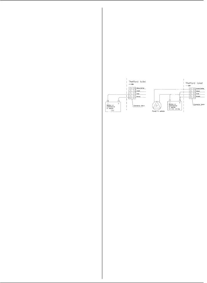
If the toilet is connected to a pressurised system:
The brown wire is positive The blue wire is negative
Do not connect the black wire Drawing 19A Do not connect the black and white wire
If the toilet is connected to a water supply system that is not pressurised:
The brown wire is positive The blue wire is negative
The black wire is positive Drawing 19B Black and white wire: to the + connection of the pump
19A. 19B.
20.Before installation, the toilet must first be connected to the water supply system. Use a hose bushing for this. (The inside diameter of the hose is 10 mm (3/8 inch). Fasten the hose with a hose clip. (See drawing 13)
21.Place the toilet in the correct position (See drawing 14) and screw the toilet on to the floor with 4 screws (4,5 x 55)
22.Now cut the sawn-out panel from the caravan wall to fit the door frame using template no. 4A or 4B, depending on whether the door is right-hand or lefthand hung. Make sure that the decorative stripes on the panel are in line with those on the caravan. (See drawing 15)
23.Fill the groove of the door outer with sealant. (16). Then position the panel in the door outer. Fix the clips to the door inner, make sure that the two clips with the arrow are mounted on this location (See diagram no.17), and then push the door inner into the door outer. Fill in the groove of the frame to be placed in the opening (=3) with sealant (See drawing 18), place the complete door against the outside wall of the caravan and fasten the door with 9 sheetmetal screws (4.2 x 12.5 mm.)
24.Seal the space between the door and the toilet from the outside. Also seal the gaps between the toilet and the side walls, between the toilet and the rear wall and between the toilet and the shower tray (or floor). (See drawings 19 + 20)

Thetford Cassette C-200 CS
Allgemeine Informationen
Produktangaben
C-200 CS aftermarket
Wichtig: Wir empfehlen Ihnen, die Thetford Cassette von Ihrem Händler einbauen zu lassen.
Die Thetford Cassette C-200 ist eine in den Sanitärbereich integrierte Toilette für Wohnwagen und Camper. Die C-200 CS Cassette Toilette wird an das Wassersystem des Fahrzeugs angeschlossen; Spülung findet mit Hilfe eines Magnetventils (12V) statt. Wir raten, den Tropfrand der Toilette zu benutzen. Darunter kann die Duschwanne mit senkrechter Kante angeschlossen werden. Das verhindert Leckagen beim Benutzen der Dusche. Die Cassette C-200 kann auch in einen Wohnwagen ohne Duschwanne eingebaut werden.
Angaben zur Installation
1.Der Sanitarbereich muß minimal 500 mm breit und - von der Rückwand aus gemessen - 500 mm tief sein. Im Hinblick auf die Toilettenbrille muß die lichte Höhe 822 mm betragen. In Fußbodenhöhe befindet sich an der Rückseite ein Durchlaß fur das Heizungsrohr (Ø 65 mm), die Wasserleitung (Ø 16 mm, x 3) und das Anschlußkabel (Ø 8 mm, x 2). Beim Anbringen des Heizungsrohrs empfiehit es sich, den mitgelieferten Luftkanal (Plenum) zu benutzen (Abb. 2).
2.Wenn sich die Toilette in der Nähe des Radkastens befindet, mussen sich mindestens 20 mm zwischen der Zierleiste des Radkastens und der einzuschneidenden Öffnung befinden. Befindet die Toilette sich hinten im Wohnwagen, so ist der Abstand zwischen der einzuschneidenden Offnung und der Ruckwand des Wohnwagens ebenfalls 20 mm (Abb. 5 + 6).
3.Es muß eine senkrechte Rückwand, an der die Toilette montiert werden kann, vorhanden sein. Die minimale Höhe der Rückwand muß 538 mm sein.
4.Ein Holzrahmen oder 3 mm dicke Aluminiumprofile müssen in die Türöffnung zwecks guter Befestigung der Tür eingesetzt werden. Der Rahmen wird in der Türöffnung für zusätzliche Verstärkung an die Wand geleimt (Abb. 10).
5.Thetford empfiehlt, den Türrahmen so einzusetzen, daß die Türscharniere in Fahrtrichtung zeigen.
6.Fragen Sie Ihren Wohnwagenhändler, wie Sie ohne Schaden ein Stück aus der Wohnwagenwand herausschneiden können.
7.Für die C-200 CS wird eine 12 V Gleichstromanlage mit Akku oder Transformator benotigt. (min. 5 Amp.)
8.Damit eine gute Spülung gewährleistet wird, sollte der Toiletteneinlaß den folgenden Anforderungen entsprechen:
-Minimumdruck 0,5 bar.
-Minimaler Durchfluß 6 L/min.
9.Manche Wagen sind mit Hochdruckwasserpumpen ausgestattet, was zu einer zu großen Wasserzufuhr führen kann. Nötigenfalls kann der mit der Toilette mitgelieferte Drosselkorper verwendet werden
(zusammen mit den Schrauben verpackt). Dieser ist auf gleicher Hohe wie der Anschlul3 in die Wasserleitung einzubauen .
Praktische Tips
-Zur Erleichterung des Einbaus werden Zeichnungen mitgeliefert, mit denen Schablonen anzufertigen sind.
-Die Einbauanleitung muß genauestes befolgt werden. Benötigtes Handwerkszeug:
*elektrische Bohrmaschine
*3 und 8 mm Bohrer
*elektrische Säge
*Kreuzschlitzschraubendreher nr. 2
*Priem
*Schutzbrille
*Zeichenstift
*Butyl kautschuk
*Schutzfolie
*Durchführungstülle fur Schlauch mit einem Innendruchmesser von 10 mm
*2 Schlauchklemmen für 16 mm Schlauch
Das aus der Wohnwagenwand herausgeschnittene Stück wird als Türfutter verwendet; sägen oder bohren Sie deshalb nur an den angegebenen Stellen.
 Loading...