

Page 1

User’s Guide
January 2002 AAP Data Acquisition (Dallas)
SLAU081
Page 2

IMPORTANT NOTICE
Texas Instruments Incorporated and its subsidiaries (TI) reserve the right to make corrections, modifications,
enhancements, improvements, and other changes to its products and services at any time and to discontinue
any product or service without notice. Customers should obtain the latest relevant information before placing
orders and should verify that such information is current and complete. All products are sold subject to TI’s terms
and conditions of sale supplied at the time of order acknowledgment.
TI warrants performance of its hardware products to the specifications applicable at the time of sale in
accordance with TI’s standard warranty . Testing and other quality control techniques are used to the extent TI
deems necessary to support this warranty . Except where mandated by government requirements, testing of all
parameters of each product is not necessarily performed.
TI assumes no liability for applications assistance or customer product design. Customers are responsible for
their products and applications using TI components. T o minimize the risks associated with customer products
and applications, customers should provide adequate design and operating safeguards.
TI does not warrant or represent that any license, either express or implied, is granted under any TI patent right,
copyright, mask work right, or other TI intellectual property right relating to any combination, machine, or process
in which TI products or services are used. Information published by TI regarding third–party products or services
does not constitute a license from TI to use such products or services or a warranty or endorsement thereof.
Use of such information may require a license from a third party under the patents or other intellectual property
of the third party , or a license from TI under the patents or other intellectual property of TI.
Reproduction of information in TI data books or data sheets is permissible only if reproduction is without
alteration and is accompanied by all associated warranties, conditions, limitations, and notices. Reproduction
of this information with alteration is an unfair and deceptive business practice. TI is not responsible or liable for
such altered documentation.
Resale of TI products or services with statements different from or beyond the parameters stated by TI for that
product or service voids all express and any implied warranties for the associated TI product or service and
is an unfair and deceptive business practice. TI is not responsible or liable for any such statements.
Mailing Address:
Texas Instruments
Post Office Box 655303
Dallas, Texas 75265
Copyright 2002, Texas Instruments Incorporated
Page 3

EVM IMPORTANT NOTICE
Texas Instruments (TI) provides the enclosed product(s) under the following conditions:
This evaluation kit being sold by TI is intended for use for ENGINEERING
DEVELOPMENT OR EVALUATION PURPOSES ONLY and is not considered by TI to
be fit for commercial use. As such, the goods being provided may not be complete in terms
of required design-, marketing-, and/or manufacturing-related protective considerations,
including product safety measures typically found in the end product incorporating the
goods. As a prototype, this product does not fall within the scope of the European Union
directive on electromagnetic compatibility and therefore may not meet the technical
requirements of the directive.
Should this evaluation kit not meet the specifications indicated in the EVM User’s Guide,
the kit may be returned within 30 days from the date of delivery for a full refund. THE
FOREGOING WARRANTY IS THE EXCLUSIVE WARRANTY MADE BY SELLER TO
BUYER AND IS IN LIEU OF ALL OTHER WARRANTIES, EXPRESSED, IMPLIED, OR
STATUTORY, INCLUDING ANY WARRANTY OF MERCHANTABILITY OR FITNESS
FOR ANY PARTICULAR PURPOSE.
The user assumes all responsibility and liability for proper and safe handling of the goods.
Further, the user indemnifies TI from all claims arising from the handling or use of the
goods. Please be aware that the products received may not be regulatory compliant or
agency certified (FCC, UL, CE, etc.). Due to the open construction of the product, it is
the user’s responsibility to take any and all appropriate precautions with regard to
electrostatic discharge.
EXCEPT TO THE EXTENT OF THE INDEMNITY SET FORTH ABOVE, NEITHER
PARTY SHALL BE LIABLE TO THE OTHER FOR ANY INDIRECT, SPECIAL,
INCIDENTAL, OR CONSEQUENTIAL DAMAGES.
TI currently deals with a variety of customers for products, and therefore our arrangement
with the user is not exclusive.
TI assumes no liability for applications assistance, customer product design,
software performance, or infringement of patents or services described herein.
Please read the EVM User’s Guide and, specifically, the EVM W arnings and Restrictions
notice in the EVM User’s Guide prior to handling the product. This notice contains
important safety information about temperatures and voltages. For further safety
concerns, please contact the TI application engineer.
Persons handling the product must have electronics training and observe good laboratory
practice standards.
No license is granted under any patent right or other intellectual property right of TI
covering or relating to any machine, process, or combination in which such TI products
or services might be or are used.
Mailing Address:
Texas Instruments
Post Office Box 655303
Dallas, Texas 75265
Copyright 2002, Texas Instruments Incorporated
Page 4

EVM WARNINGS AND RESTRICTIONS
It is important to operate this EVM within the input voltage range of ±12 V and the output
voltage range of ±12 V.
Exceeding the specified input range may cause unexpected operation and/or irreversible
damage to the EVM. If there are questions concerning the input range, please contact a TI
field representative prior to connecting the input power.
Applying loads outside of the specified output range may result in unintended operation and/or
possible permanent damage to the EVM. Please consult the EVM User’s Guide prior to
connecting any load to the EVM output. If there is uncertainty as to the load specification,
please contact a TI field representative.
During normal operation, some circuit components may have case temperatures greater than
60°C. The EVM is designed to operate properly with certain components above 60°C as long
as the input and output ranges are maintained. These components include but are not limited
to linear regulators, switching transistors, pass transistors, and current sense resistors. These
types of devices can be identified using the EVM schematic located in the EVM User’s Guide.
When placing measurement probes near these devices during operation, please be aware
that these devices may be very warm to the touch.
Mailing Address:
Texas Instruments
Post Office Box 655303
Dallas, Texas 75265
Copyright 2002, Texas Instruments Incorporated
Page 5

Running Title—Attribute Reference
Contents
1 Introduction 1-1. . . . . . . . . . . . . . . . . . . . . . . . . . . . . . . . . . . . . . . . . . . . . . . . . . . . . . . . . . . . . . . . . . . . .
1.1 EVM Modes 1-2. . . . . . . . . . . . . . . . . . . . . . . . . . . . . . . . . . . . . . . . . . . . . . . . . . . . . . . . . . . . . . . .
1.1.1 Stand-Alone Mode 1-3. . . . . . . . . . . . . . . . . . . . . . . . . . . . . . . . . . . . . . . . . . . . . . . . . . .
1.1.2 User Mode 1-3. . . . . . . . . . . . . . . . . . . . . . . . . . . . . . . . . . . . . . . . . . . . . . . . . . . . . . . . .
1.2 Analog Input Conditioning 1-3. . . . . . . . . . . . . . . . . . . . . . . . . . . . . . . . . . . . . . . . . . . . . . . . . . .
1.3 Analog Output Conditioning 1-3. . . . . . . . . . . . . . . . . . . . . . . . . . . . . . . . . . . . . . . . . . . . . . . . . .
1.4 Prototype Area 1-3. . . . . . . . . . . . . . . . . . . . . . . . . . . . . . . . . . . . . . . . . . . . . . . . . . . . . . . . . . . . .
2 Getting Started 2-1. . . . . . . . . . . . . . . . . . . . . . . . . . . . . . . . . . . . . . . . . . . . . . . . . . . . . . . . . . . . . . . . . .
2.1 Shipping (Default Configuration) 2-2. . . . . . . . . . . . . . . . . . . . . . . . . . . . . . . . . . . . . . . . . . . . . .
2.2 Jumpers 2-4. . . . . . . . . . . . . . . . . . . . . . . . . . . . . . . . . . . . . . . . . . . . . . . . . . . . . . . . . . . . . . . . . . .
2.2.1 Analog I/O Signal Conditioning 2-4. . . . . . . . . . . . . . . . . . . . . . . . . . . . . . . . . . . . . . . .
2.2.2 Channel 0 Analog Input 2-4. . . . . . . . . . . . . . . . . . . . . . . . . . . . . . . . . . . . . . . . . . . . . .
2.2.3 Channel 0 Analog Output 2-5. . . . . . . . . . . . . . . . . . . . . . . . . . . . . . . . . . . . . . . . . . . . .
2.2.4 Signal Generator 2-5. . . . . . . . . . . . . . . . . . . . . . . . . . . . . . . . . . . . . . . . . . . . . . . . . . . .
2.2.5 Voltage Reference 2-5. . . . . . . . . . . . . . . . . . . . . . . . . . . . . . . . . . . . . . . . . . . . . . . . . . .
2.2.6 ADC Supply Voltage 2-5. . . . . . . . . . . . . . . . . . . . . . . . . . . . . . . . . . . . . . . . . . . . . . . . .
2.2.7 Clock/Timer Routing 2-6. . . . . . . . . . . . . . . . . . . . . . . . . . . . . . . . . . . . . . . . . . . . . . . . .
2.3 Switches 2-6. . . . . . . . . . . . . . . . . . . . . . . . . . . . . . . . . . . . . . . . . . . . . . . . . . . . . . . . . . . . . . . . . .
2.3.1 Stand-Alone-Mode, SW1-1 2-6. . . . . . . . . . . . . . . . . . . . . . . . . . . . . . . . . . . . . . . . . . .
2.4 Connectors 2-7. . . . . . . . . . . . . . . . . . . . . . . . . . . . . . . . . . . . . . . . . . . . . . . . . . . . . . . . . . . . . . . .
2.5 ADC and DAC Direct Access 2-11. . . . . . . . . . . . . . . . . . . . . . . . . . . . . . . . . . . . . . . . . . . . . . . .
2.6 Host Communication 2-1 1. . . . . . . . . . . . . . . . . . . . . . . . . . . . . . . . . . . . . . . . . . . . . . . . . . . . . . .
2.6.1 Common Connector 2-12. . . . . . . . . . . . . . . . . . . . . . . . . . . . . . . . . . . . . . . . . . . . . . . .
2.6.2 Legacy Connector 2-14. . . . . . . . . . . . . . . . . . . . . . . . . . . . . . . . . . . . . . . . . . . . . . . . . .
A Bill of Materials, Board Layout, and Schematics A-1. . . . . . . . . . . . . . . . . . . . . . . . . . . . . . . . . . .
Chapter Title—Attribute Reference
v
Page 6

Running Title—Attribute Reference
Figures
2–1 SAM Configuration 2-2. . . . . . . . . . . . . . . . . . . . . . . . . . . . . . . . . . . . . . . . . . . . . . . . . . . . . . . . . . . .
Tables
2–1 Default Switch Settings 2-3. . . . . . . . . . . . . . . . . . . . . . . . . . . . . . . . . . . . . . . . . . . . . . . . . . . . . . . .
2–2 Default Jumper Settings 2-3. . . . . . . . . . . . . . . . . . . . . . . . . . . . . . . . . . . . . . . . . . . . . . . . . . . . . . .
2–3 Jumper/Function Reference 2-4. . . . . . . . . . . . . . . . . . . . . . . . . . . . . . . . . . . . . . . . . . . . . . . . . . . .
vi
Page 7

Chapter 1
Introduction
This chapter contains an overview of the features and functions of the EVM.
Topic Page
1.1 EVM Modes 1–2. . . . . . . . . . . . . . . . . . . . . . . . . . . . . . . . . . . . . . . . . . . . . . . . . . .
1.2 Analog Input Conditioning 1–3. . . . . . . . . . . . . . . . . . . . . . . . . . . . . . . . . . . . .
1.3 Analog Output Conditioning 1–3. . . . . . . . . . . . . . . . . . . . . . . . . . . . . . . . . . .
1.4 Prototype Area 1–3. . . . . . . . . . . . . . . . . . . . . . . . . . . . . . . . . . . . . . . . . . . . . . .
1-1
Page 8

EVM Modes
This user’s guide has been written to help you get the most from your
evaluation module (EVM). The TLC4541 EVM is a member of the
multipurpose (MP) family of serial EVMs. It provides a platform to demonstrate
the performance and functionality of the TLC4541 ADC and the
TLV5636 DAC.
TI’s websites are regularly updated. They present the latest software
additions, development information, troubleshooting help, general
background, as well as all applicable data sheets.
For specific questions related to this EVM or device send an email to the
Analog Applications Team at dataconvapps@list.ti.com and reference the
orderable tool description – TLC4541 EVM.
This user’s guide is divided into the following chapters:
- Chapter 1 offers an overview of the EVM and introduces the general
features and functions of the system.
- Chapter 2 describes the operation of the EVM from a user’s view . It details
options that can be modified, connectors used, and pinout details.
- Appendix A details the bill of materials (BOM) and the schematic, along
with explanations of certain EVM features.
1.1 EVM Modes
This EVM has been designed, tested, and shipped in a condition that enables
the user to begin evaluation with minimal effort.
There are basically two operating modes for the EVM. These modes are
mutually exclusive. They are:
- Stand-Alone Mode (SAM)
Stand-alone mode enables the user to check the system without the
support of a signal generator, pattern generator , or DSP. In this mode, the
digital output from the ADC is fed into the companion DAC and
reconstructed.
User mode is deselected if SAM is selected. The DSP will be unable to
communicate with either the ADC or the DAC.
- User Mode
The EVM typically operates via a DSP or a microprocessor. In this mode
the user is responsible for generating all the control signals. If user mode is
selected, SAM is deselected.
1-2
Page 9

1.1.1 Stand-Alone Mode
A unique feature of this EVM is the facility it offers the user to closely couple
the ADC and DAC with a minimum of user intervention. This feature allows the
serial bit stream from the digitized analog output to be fed directly to the DAC.
Therefore, the signal that is fed into the ADC can be reconstructed via the
DAC. No DSP need be present.
SAM is selected by:
- Switching SW1-1 to the on position, LED is on.
1.1.2 User Mode
The user can connect the ADC to a DSP or to a microprocessor in two ways:
- Via IDC ribbon cable
- Via daughterboard connectors J16 and J17
User mode is selected by:
- Switching SW1-1 to the of f position, LED is off.
Analog Input Conditioning
For example, TI’s range of DSP starter kits (DSK modules) provides a simple
low-cost solution, offering a range of DSK modules for most needs. The EVM
also supports the TMS320C6000 daughtercard specification (SPRA711), in
addition to providing support for the Motorola specification for data
transfer (SPI).
1.2 Analog Input Conditioning
There are a number of methods to connect analog input signals to the EVM.
Chapter 2 discusses these alternatives.
1.3 Analog Output Conditioning
There are a number of methods to connect analog output signals to the EVM.
Chapter 2 discusses these alternatives.
1.4 Prototype Area
An area of the PWB has been set aside if none of the signal conditioning
options provided are suitable.
The prototype area has the following features:
- A matrix of plated-through holes (PTH)
- SMT pads in a standard 14-pin JEDEC footprint
- Convenient points to pick up all power options
Introduction
1-3
Page 10

Chapter 2
Getting Started
This chapter describes how the user can modify the various options of
this EVM.
Topic Page
2.1 Shipping (Default Configuration) 2-2. . . . . . . . . . . . . . . . . . . . . . . . . . . . . . .
2.2 Jumpers 2-4. . . . . . . . . . . . . . . . . . . . . . . . . . . . . . . . . . . . . . . . . . . . . . . . . . . . .
2.3 Switches 2-6. . . . . . . . . . . . . . . . . . . . . . . . . . . . . . . . . . . . . . . . . . . . . . . . . . . . .
2.4 Connectors 2-7. . . . . . . . . . . . . . . . . . . . . . . . . . . . . . . . . . . . . . . . . . . . . . . . . . .
2.5 ADC and DAC Direct Access 2-11. . . . . . . . . . . . . . . . . . . . . . . . . . . . . . . . . .
2.6 Host Communication 2-11. . . . . . . . . . . . . . . . . . . . . . . . . . . . . . . . . . . . . . . . .
Getting Started
2-1
Page 11

Shipping (Default Configuration)
It is very important that users feel comfortable with the EVM from the
beginning. To achieve this, each unit is manufactured and shipped in a
predetermined condition. This allows the user to begin evaluation of the
system immediately and to have confidence that the EVM is working.
To confirm that the EVM is working properly, follow the steps below:
1) Apply power to the system. The green LED will illuminate.
2) Ensure stand-alone mode (SAM) LED is on.
3) Check TP7 via oscilloscope. This will be a sine wave.
4) Press the reset button SW3.
5) Press the start button SW2.
6) Check TP20 with an oscilloscope. If the system is working properly, the
signal at TP20 will also be a sine wave.
The system works as illustrated below. Any analog input supplied to the ADC
will be digitized and reconstructed by the DAC.
Figure 2–1.SAM Configuration
TP7
ADC
DAC
TP20
The user may probe the data and control signals to observe the signals that
allow stand-alone mode to function.
2.1 Shipping (Default Configuration)
The EVM is tested and shipped with jumpers and switches in a predetermined
arrangement. This arrangement enables users to verify at once that the EVM
is working. The tables below list switch and jumper settings that the EVM
should be set to upon receipt.
Data
Data
Control
Electronics
DSP / Micro
Interface
2-2
Page 12

Shipping (Default Configuration)
Th
clock. This has been designed to be as flexible as ossible to
Table 2–1.Default Switch Settings
Switch Settings
Default
Configuration
SW1-1 On Stand-alone mode is selected, LED is on
SW1-2 Off Reserved
SW1-3 Off Reserved
SW1-4 Off Reserved
Description
Table 2–2.Default Jumper Settings
Jumper Settings
Default Configuration Description
Pins 1–2 Pins 2–3
W1 Inserted Not inserted Input for channel 0 is via BNC connector J1.
W2 Not inserted Inserted Sine wave test signal is selected for channel 0.
W3 Not inserted Inserted Sine wave test signal is output for channel 0.
W4 Not inserted Inserted Onboard conditioned input for channel 0 is selected.
W5 Not populated Not populated
W6 Not populated Not populated
W7 Not populated Not populated
W8 Not populated Not populated
W9 Not inserted Disables onboard sine and triangle wave generator
W10 Inserted Not inserted SCLK routed to ADC
W11 Not inserted Inserted Signal conditioning output selected for channel 0
W12 Inserted Not inserted FS routed to ADC
W13 Not Inserted 5-V analog
W14 Inserted EVM reference or DAC’s on-chip reference selected.
W15 Not populated Not populated
W16 Inserted Not inserted Selects internal or external reference
W17 Inserted Not inserted Determines EVM reference voltage
W18 Not inserted Inserted FS routed to DAC
W19 Inserted Not inserted Selects source of signal conditioning output from DAC
W20 Not inserted
W21 Inserted Not inserted
W22 Inserted Not inserted
W23 Inserted Not inserted
W24 Not inserted
W25 Not populated Not populated
ese jumpers determine various options for supplying system
clock. This has been designed to be as flexible as possible to
accommodate many potential options.
p
p
pp
The hardware that can be reconfigured falls into one of the following sections:
- Jumpers
- Switches
- Connectors
Getting Started
2-3
Page 13

Jumpers
2.2 Jumpers
The table below lists the functions that users can reconfigure along with the
shipping condition.
Table 2–3.Jumper/Function Reference
Function Reference Designator Subsection
Channel 0
Analog input W1, W1 1, W4, W2, W3 3.2.3
Analog output W14, W19, W18 3.2.4
Disable onboard signal generator W9 3.2.7
Voltage reference W16, W17 3.2.8
3.3-V/5-V analog supply select W13 3.2.9
Clock/timer routing W20, W21, W22, W23, W24 3.2.10
2.2.1 Analog I/O Signal Conditioning
The TLC4541 supports various signal conditioning configurations.
The user has the following options:
- Bypass signal conditioning
- Use the onboard signal conditioning. This consists of an operational
amplifier for each input channel configured with a gain of 1.
- Use the prototype area for signal conditioning.
- Use the expansion connector via a TI universal operational amplifier
evaluation module (such as SLOP224/SLOP249).
2.2.2 Channel 0 Analog Input
This is the primary analog input and can always be connected externally.
Analog Input Configuration Channel 0
Reference
Designator
W1 W1 allows the user to select between an analog input via BNC – J1 or IDC – J4 pin 1.
W11 W1 1 allows selection of either the conditioned or nonconditioned analog input signal.
W4 W4 allows the user to select either the prototype area output or the output from W1 1.
W2 W2 enables the user to select either the output from the expansion connector or the output
from the onboard signal generator.
W3 W3 completes the selection choices for channel 0 by determining if the output from W2 or W4
is chosen to be presented to the ADC.
Functional Description
2-4
Page 14

2.2.3 Channel 0 Analog Output
With a one-channel DAC installed, this signal is the primary analog output
(output A).
With a two-channel DAC installed, the pinout of these devices effectively
resolves this channel to be the secondary analog output (output B).
Analog Input Configuration Channel 0
Reference
Designator
W19 This jumper selects the source for the analog output on channel 0.
When a jumper is installed between pins 1 and 2, the output from the expansion connector’s
B-channel is routed out.
When the jumper is installed between pins 2 and 3, the output from the onboard signal
conditioning is directed through channel 0.
Functional Description
2.2.4 Signal Generator
Signal Generator
Reference
Designator
W9 W9 controls the generation of both onboard test signals. A jumper installed between pins 1 and 2
disables the waveform generator.
Functional Description
Jumpers
2.2.5 Voltage Reference
V oltage Reference
Reference
Designator
W16 W16 selects either the onboard reference or an external reference supplied by the user.
W17 W17 allows the user to vary the reference voltage.
W14 There are a number of possible DACs that a user can install on this EVM. Some have an internal
reference that the user can select via software, and some do not have an internal reference. For
the DACs that support an internal reference, it is important to have the facility to remove the
external reference supplied by the EVM (or user) to avoid conflicts between the DAC’s internal
reference and the external reference.
Functional Description
2.2.6 ADC Supply Voltage
ADC Supply Voltage
Reference
Designator
W13 This jumper controls the analog supply voltage.
When the jumper is installed, the supply voltage to the ADC is 3.3 V.
When the jumper is not installed, the supply voltage to the ADC is 5 V.
Functional Description
Getting Started
2-5
Page 15

Switches
2.2.7 Clock/Timer Routing
A variety of options are available to the user. Be careful about altering these.
Clock/Timer Routing
Reference
Designator
W21 This jumper defines the clock that the ADC and DAC use for all their timing. The user can select
either the output from W23 or the output from W22 to be the base clock for the system.
W23 This jumper allows the user to select either an external clock, or the onboard 20-MHz oscillator for
conversion. In addition, this signal is fed to W20.
W20 W20 provides a route for the EVM to generate CLKS for a DSP if so desired.
W22 This jumper enables the user to select either the transmit clock from a DSP, or the output
from W24.
W24 W24 connects or isolates the timer output from a DSP.
Functional Description
2.3 Switches
There are three switches present on the EVM:
- One 8-pin DIL switch which houses four individual switches; these are
denoted SW1-1, SW1-2, SW1-3, and SW1-4.
- Two momentary push-button switches
Features and functions of each switch:
Reference
Designator
SW1-1 Selects either stand-alone mode (SAM) or user mode SAM
SW1-2 Reserved
SW1-3 Reserved
SW1-4 Reserved
2.3.1 Stand-Alone-Mode, SW1-1
SW1-1 chooses either stand-alone mode or user mode. If the switch is set to
the off position, SAM is selected and the EVM ignores all signals generated
by a DSP. In addition, the EVM will not output any signals to a DSP or
microprocessor.
In this mode, SW2 and SW3 are used to reset the EVM’s logic and initiate
automatic conversions from the ADC, in addition to automatically routing the
serial bit stream from the ADC to the DAC for reconstruction.
Function
Default
Condition
Reference
Designator
SW2 Initiates ADC and DAC conversions in SAM
SW3 Forces the EVM’s control logic into a known state
2-6
Function
Page 16

2.4 Connectors
g
lifi
evaluation board, SIL
Connectors
If SW1-1 is set to the on position, user mode is selected. In this case the user
has absolute control of the data and control signals for the ADC and DAC. With
SW1-1 in the on position, the logic that generates the control for SAM is
disabled and plays no active part in the process.
In addition to jumpers and switches, the user also has access to various
connectors. This section details the pinout of each connector.
Reference
Designator
J1 Analog input option for channel 0, miniature BNC
Description
Cells in grey are not supported (tracked) directly by this EVM.
Reference
Designator
J3 Analog input option
Description
for universal
p
operational-amp
evaluation board, SIL
PTH not installed.
Pin
Number
1 Noninverting input signal to dual operational amplifier, (2)
p
er
2 Noninverting input signal to dual operational amplifier, (2)
3 Inverting input signal to dual operational amplifier, (2)
4 Inverting input signal to dual operational amplifier, (2)
5 Nonfiltered output from dual operational amplifier, (2)
6 Filtered output from dual operational amplifier, (2)
7 +V supply
8 Operational amplifier (2) shutdown signal
9 Reference voltage
10 Analog ground
11 Operational amplifier (1) shutdown signal
12 –V supply
13 Nonfiltered output from dual operational amplifier, (1)
14 Filtered output from dual operational amplifier, (1)
15 Noninverting input signal to dual operational amplifier, (1)
16 Noninverting input signal to dual operational amplifier, (1)
17 Inverting input signal to dual operational amplifier, (1)
18 Inverting input signal to dual operational amplifier, (1)
Function
Getting Started
2-7
Page 17

Connectors
g,
Reference
Designator
Description
J4 Analog input option, 26-pin
DIL header
Pin
Number
1 Channel 0 input
2 AGND
3 Channel 1 input
4 AGND
5 Not connected
6 AGND
7 Not connected
8 AGND
9 Not connected
10 AGND
11 Not connected
12 AGND
13 Not connected
14 AGND
15 Not connected
16 AGND
17 Not connected
18 AGND
19 Not connected
20 AGND
21 Not connected
22 AGND
23 Not connected
24 AGND
25 External reference voltage
26 AGND
Function
Reference
Designator
J5 Analog output for one-channel DAC
2-8
Description
Page 18

Connectors
g,
Reference
Designator
Description
J7 EVM power
J8 Analog output option,
26-pin DIL header
Pin
Number
Function
1 5 V
2 –12 V
3 0 V
4 12 V
1 No output
2 AGND
3 Analog output for one-channel DAC
4 AGND
5 Not connected
6 AGND
7 Not connected
8 AGND
9 Not connected
10 AGND
11 Not connected
12 AGND
13 Not connected
14 AGND
15 Not connected
16 AGND
17 Not connected
18 AGND
19 Not connected
20 AGND
21 Not connected
22 AGND
23 Not connected
24 AGND
25 Not connected
26 AGND
Getting Started
2-9
Page 19

Connectors
g
lifi
evaluation board, SIL
Reference
Designator
Description
J9 Analog input option
for universal
p
operational-amp
evaluation board, SIL
PTH not installed.
Pin
Number
Function
1 Noninverting input signal to dual operational amplifier, (2)
p
er
2 Noninverting input signal to dual operational amplifier, (2)
3 Inverting input signal to dual operational amplifier, (2)
4 Inverting input signal to dual operational amplifier, (2)
5 Nonfiltered output from dual operational amplifier, (2)
6 Filtered output from dual operational amplifier, (2)
7 +V supply
8 Operational amplifier (2) shutdown signal
9 Reference voltage
10 Analog ground
11 Operational amplifier (1) shutdown signal
12 –V supply
13 Nonfiltered output from dual operational amplifier, (1)
14 Filtered output from dual operational amplifier, (1)
15 Noninverting input signal to dual operational amplifier, (1)
16 Noninverting input signal to dual operational amplifier, (1)
17 Inverting input signal to dual operational amplifier, (1)
18 Inverting input signal to dual operational amplifier, (1)
2-10
Page 20

2.5 ADC and DAC Direct Access
gg
gg
J10 and J1 1 offer users the facility to directly inspect the digital signals coming
from and going to the ADC and DAC.
ADC and DAC Direct Access
Reference
Designator
J10 Allows the user direct access to all digital signals for the ADC
J11 Allows the user direct access to all digital signals for the DAC
Description
Pin
Number
1 Digital ground
2 SDO
3 Digital ground
4 SCLK
5 Digital ground
6 CS or CS/FS
7 Digital ground
8 FS
1 Digital ground
2 SDI
3 Digital ground
4 SCLK
5 Digital ground
6 CS
7 Digital ground
8 FS
Signal
2.6 Host Communication
There are two ways to connect a host system (DSP/microprocessor):
- Texas Instruments’ new DSKs provide two dedicated 80-pin connectors.
The EVM can be plugged directly onto these DSKs. This connector
standard is referred to as the common connector.
- Legacy DSKs not equipped with the 80-pin common connectors will
communicate via the daisy-chained legacy header.
The following sections discuss each connection method.
Getting Started
2-11
Page 21

Host Communication
y
2.6.1 Common Connector
Reference
Designator
J16 80-pin memory interface connector for ’C5000 and ’C6000 DSK
EVMs. Pins unused by this EVM are omitted for clarity .
Description
Pin
Number
1 5 V
2 5 V
11 PCI ground
12 PCI ground
21 5 V
22 5 V
29 PCI ground
30 PCI ground
31 PCI ground
32 PCI ground
41 3.3 V
42 3.3 V
51 PCI ground
52 PCI ground
61 PCI ground
62 PCI ground
71 PCI ground
72 PCI ground
79 PCI ground
80 PCI ground
Function
2-12
Page 22

Host Communication
Reference
Designator
Description
J17 80-pin peripheral and control connector for ’C5000 and ’C6000
DSK EVMs. Pins unused by this EVM are omitted for clarity.
Pin
Number
Function
1 12 V
2 –12 V
3 PCI ground
4 PCI ground
5 5 V
6 5 V
7 PCI ground
8 PCI ground
9 5 V
10 5 V
35 FSX
33 CLKX
36 DX
25 PCI ground
26 PCI ground
39 CLKR
41 FSR
42 DR
31 PCI ground
32 PCI ground
37 PCI ground
38 PCI ground
43 PCI ground
44 PCI ground
45 TOUT
49 XF
51 PCI ground
52 PCI ground
61 PCI ground
62 PCI ground
76 PCI ground
77 PCI ground
79 PCI ground
80 PCI ground
Getting Started
2-13
Page 23

Host Communication
2.6.2 Legacy Connector
J12, J13, and J15 are three 2x20 headers daisy-chained together and are
collectively referred to as the legacy connector. The principle behind this
arrangement is to eliminate the confused and untidy custom cabling that is
typically present when connecting a legacy DSP to an EVM. This
daisy-chained connector method is flexible, robust, and makes it possible to
use a standard flat signal-cable assembly, improving reliability of
communications between host and EVM.
Two shorting bars are inserted in J12 and J15; these bars permit alternate pins
on J13 to be DGND. If the user has complete discretion over signal routing at
the host end, it is recommended that the host-end connector should reflect the
same pinout as J13.
However, if the host-end connector does not (or cannot) mirror the pinout for
J13, then some degree of signal-twisting is necessary. This is accomplished
on the EVM by removing the shorting bars on J12 and J15 and typically
wire-wrapping directly onto the appropriate header.
For example, if the host connector on the DSP has the pin assignment
described in the following table, then a 1:1 mapping is possible and the user
should plug a flat 20-way ribbon cable into J13.
Host Connector EVM Connector – J13
Pin No. Signal Pin No. Signal Pin No. Signal Pin No. Signal
1 XF 2 DGND 1 XF 2 DGND
3 CLKX 4 DGND 3 CLKX 4 DGND
5 CLKR 6 DGND 5 CLKR 6 DGND
7 DX 8 DGND 7 DX 8 DGND
9 DR 10 DGND 9 DR 10 DGND
11 FSX 12 DGND 11 FSX 12 DGND
13 FSR 14 DGND 13 FSR 14 DGND
15 Resvd 16 DGND 15 Resvd 16 DGND
17 CLKS 18 DGND 17 CLKS 18 DGND
19 TOUT 20 DGND 19 TOUT 20 DGND
However, if the host connector has a different signal pinout, the user should
remove the shorting bars from J12 and J15. A flat 20-way IDC ribbon cable can
still be used; in this case, the user should plug the connector into J12 of the
EVM. Since the cable is now plugged into J12, and all the signals on both sides
of the J12 pins are routed to adjacent connector pins (J13 and J15), the user
can typically wire-wrap the associated host signal to the relevant EVM signal.
The example shown below demonstrates the steps that must be taken to
reassign the connector and wire-wrap the correct signals.
2-14
Page 24

Host Communication
Consider a host cable signal assignment as shown below:
Host Connector
Pin No. Signal Pin No. Signal
1 NA 2 DGND
3 NA 4 DGND
5 CLKX 6 CLKR
7 TOUT 8 DGND
9 DX 10 DR
11 FSX 12 FSR
13 NA 14 DGND
15 XF 16 DGND
17 NA 18 NA
19 NA 20 CLKS
The host connector mates with J12. Signals on either side of J12 are available
on J13 and J15.
J13 Host Connector Plugged into J12 J15
Pin No. Pin No. Signal Pin No. Signal Pin No.
2 1 N/A 2 DGND 1
4 3 N/A 4 DGND 3
6 5 CLKX 6 CLKR 5
8 7 TOUT 8 DGND 7
10 9 DX 10 DR 9
12 11 FSX 12 FSR 11
14 13 N/A 14 DGND 13
16 15 XF 16 DGND 15
18 17 N/A 18 N/A 17
20 19 N/A 20 CLKS 19
Getting Started
2-15
Page 25

Host Communication
For clarity, the above table can be redrawn with J12 removed.
J13 J15
Pin No. Signal Pin No. Signal
2 NA 1 DGND
4 NA 3 DGND
6 CLKX 5 CLKR
8 TOUT 7 DGND
10 DX 9 DR
12 FSX 11 FSR
14 NA 13 DGND
16 XF 15 DGND
18 NA 17 NA
20 NA 19 CLKS
The table below shows the signal names and pin assignments that the
composite connector shown above must be mapped onto.
J13
Pin No. Signal
1 XF
3 CLKX
5 CLKR
7 DX
9 DR
11 FSX
13 FSR
15 Resvd
17 CLKS
19 TOUT
2-16
Page 26

Host Communication
All of the signals required to interface the EVM to the host are now available
on either J13 or J15. This is simply a matter of wire-wrapping in the following
way:
J13
Pin No. Signal Pin No. Signal
2 NA
4 NA
6 CLKX 3 CLKX
8 TOUT 19 TOUT
10 DX 7 DX
12 FSX 11 FSX
14 NA
16 XF 1 XF
18 NA
20 NA
J15
Pin No. Signal Pin No. Signal
1 DGND YES 2 DGND
3 DGND YES 4 DGND
Wire Wrap
Wire Wrap
J13
J13
Jumper
Between
J15
Pin No. Signal
5 CLKR YES 5 CLKR 6 DGND
7 DGND YES 8 DGND
9 DR YES 9 DR 10 DGND
11 FSR YES 13 FSR 12 DGND
13 DGND YES 14 DGND
15 DGND YES 16 DGND
17 NA 18 DGND
19 CLKS YES 17 CLKS 20 DGND
Getting Started
2-17
Page 27

Host Communication
All of these connectors are shown below:
Reference
Designator
J12 20-pin connector
Description
Pin
Number
1 J13 pin 2
2 J15 pin 1
3 J13 pin 4
4 J15 pin 3
5 J13 pin 6
6 J15 pin 5
7 J13 pin 8
8 J15 pin 7
9 J13 pin 10
10 J15 pin 9
11 J13 pin 12
12 J15 pin 1 1
13 J13 pin 14
14 J15 pin 13
15 J13 pin 16
16 J15 pin 15
Signal Name/Function
17 J13 pin 18
18 J15 pin 17
19 J13 pin 20
20 J15 pin 19
2-18
Page 28

Host Communication
Reference
Designator
Description
J13 20-pin signal connector
Pin
Number
Signal Name/Function
1 ADC select signal
2 J12 pin 1
3 CLKX/transmit clock
4 J12 pin 3
5 CLKR receive clock
6 J12 pin 5
7 DX/data transmit
8 J12 pin 7
9 DR/data receive
10 J12 pin 9
11 FSX/frame sync transmit
12 J12 pin 1 1
13 FSR/frame sync receive
14 J12 pin 13
15 Reserved
16 J12 pin 15
17 CLKS/sync clock
18 J12 pin 17
19 TOUT/host timer output
20 J12 pin 19
Getting Started
2-19
Page 29

Host Communication
Reference
Designator
J15 20-Pin connector
Description
Pin
Number
Signal Name/Function
1 J12 pin 2
2 DGND
3 J12 pin 4
4 DGND
5 J12 pin 6
6 DGND
7 J12 pin 8
8 DGND
9 J12 pin 10
10 DGND
11 J12 pin 12
12 DGND
13 J12 pin 14
14 DGND
15 J12 pin 16
16 DGND
17 J12 pin 18
18 DGND
19 J12 pin 20
20 DGND
2-20
Page 30

Appendix A
Bill of Materials, Board Layout, and
Schematics
This appendix contains the bill of materials, board layouts, and the EVM
schematics.
Bill of Materials, Board Layout, and Schematics
A-1
Page 31

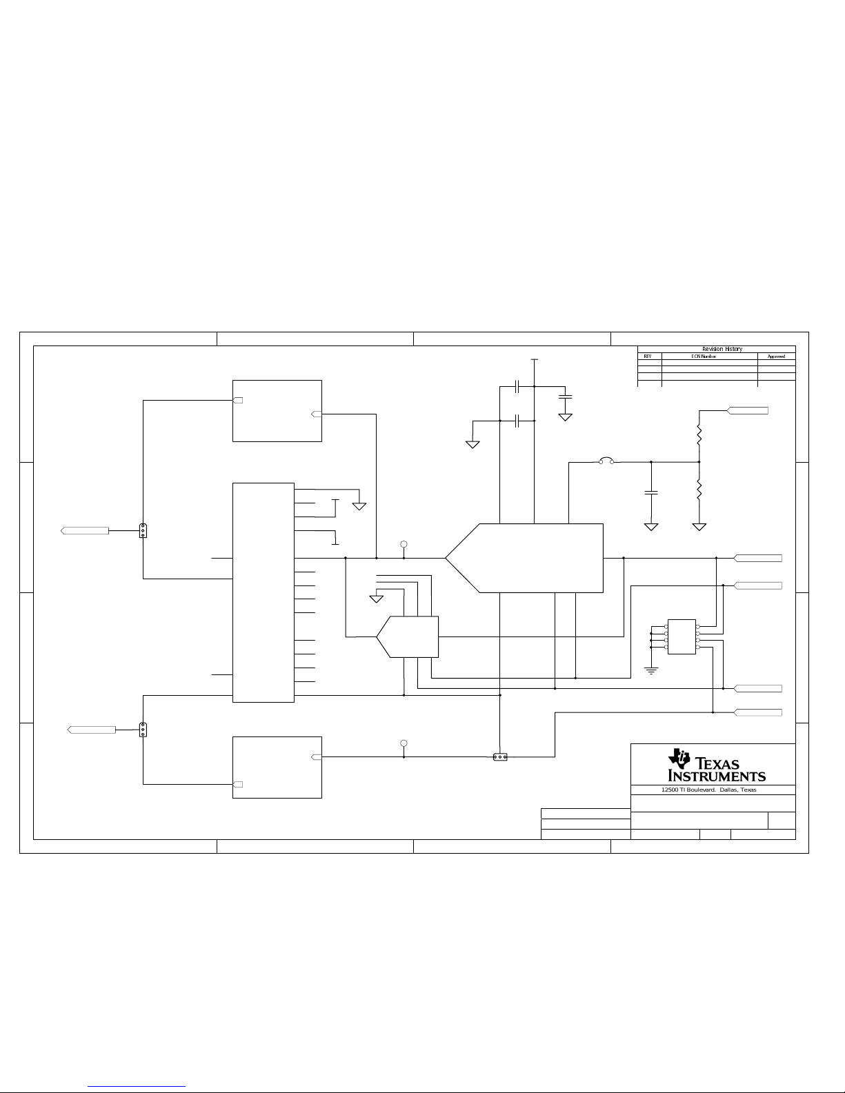
1 2 34
A
B
C
D
4
321
D
C
B
A
5HYLVLRQ+LVWRU\
5(9 (&11XPEHU $SSU RYHG
12500 TI Boulevard. Dallas, Texas 75243
TITLE:
SHEET: OF:
FILE: SIZE:
REV:
Drawn By:
Engineer:
DOCUMENT C ONTROL # :
114
Block Diagram DATE: 28-Nov-2001
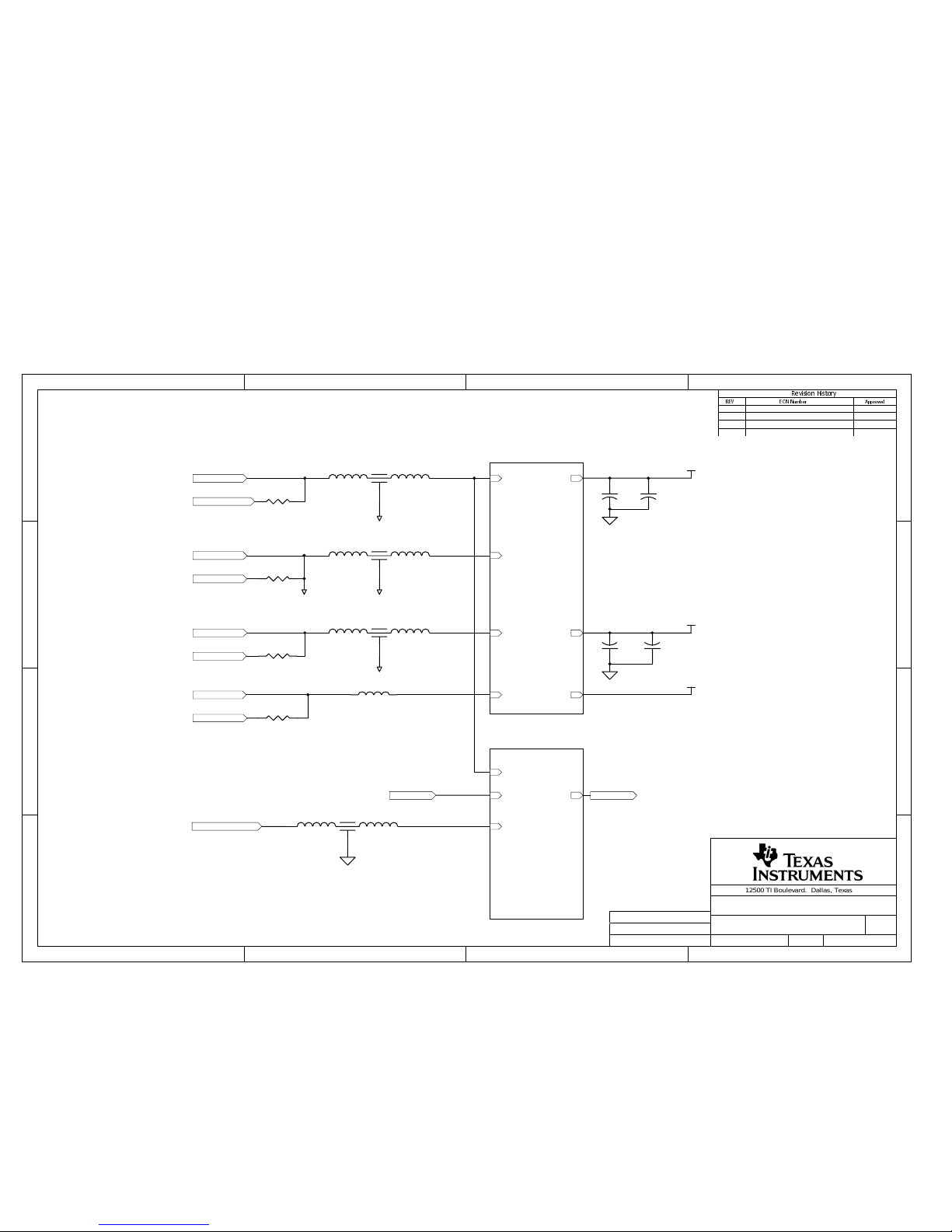
Block Diagram
6430333
A4
J6
J1
12
34
56
78
910
1112
1314
1516
1718
1920
2122
2324
2526
J4
J2
J5
+Supply
Ground
-Supply
VREFPEXT_VREFP
PCI_-12V
PCI_+12V
PCI_GND
SENSE
+5V_IN
PCI_+5v
Power & Reference
SENSE
VREFP
SENSE
VREFP
In_0
ADC_Data_out
VREFP
SENSE
In_1
LCL_CLKX
FS
LCL_CS_ADC*
ADC
AOUT
VREFP
DAC_Data_in
AOUT_A
DAC_Write*
LCL_CS_DAC*
LCL_CLKX
DAC
PCI_GND
PCI_+12V
PCI_-12V
DSP_CLKX
DSP_FSX
DSP_CLKR
DSP_FSR
DSP_XF
DSP_DX
DSP_DR
DSP_TOUT
DSP_CLKS
PCI_+5v
User connectors
ADC_Data_out
DAC_Data_in
FS
LCL_CS_DAC*
LCL_CS_ADC*
LCL_CLKX
DSP_XF
DSP_DX
DSP_CLKX
DSP_FSX
DSP_DR
DSP_FSR
DSP_CLKR
DSP_CLKS
DSP_TOUT
DAC_Write*
Interface
BNC_0
IDC_0
BNC_1
IDC_1
Channel_1
Channel_0
Inpu t Con fig
+Supply
Ground
-Supply
12
34
56
78
910
1112
1314
1516
1718
1920
2122
2324
2526
J8
+5V_IN1
2
3
4
J7
Joe Purvis
Joe Purvis
Page 32
1 2 34
A
B
C
D
4
321
D
C
B
A
5HYLVLRQ+LVWRU\
5(9 (&11XPEHU $SSU RYHG
12500 TI Boulevard. Dallas, Texas 75243
TITLE:
SHEET: OF:
FILE: SIZE:
REV:
Drawn By:
Engineer:
DOCUMENT C ONTROL # :
214
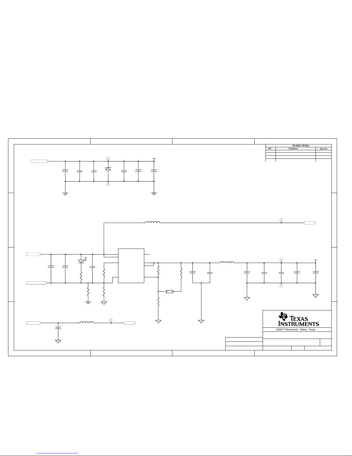
Power & Reference DATE: 28-Nov-2001
Power & Reference
6430333
A4
+Supply
Ground
-Supply
+VIN
REF_IN
-VIN
+Vs
-Vs
+DVdd +DVdd
Power
VREFP
EXT_VREFP
1
2
3
FL4
1
2
3
FL2
1
2
3
FL3
1
2
3
FL1
R69
0
R68
0
R70
0
PCI_-12V
PCI_+12V
PCI_GND
+VIN
VREFP
EXT_REFP
SENSE
Reference
SENSE
+
C10
10uF
+
C11
10uF
+VS
-VS
GND
GND
GND
+
C57
10uF
+
C56
10uF
+5V_IN
+DVdd
2 040500
R58
0
PCI_+5v
FB13
SM_FB_27--044447
GND
Joe Purvis
Joe Purvis
Page 33
1 2 34
A
B
C
D
4
321
D
C
B
A
5HYLVLRQ+LVWRU\
5(9 (&11XPEHU $SSU RYHG
12500 TI Boulevard. Dallas, Texas 75243
TITLE:
SHEET: OF:
FILE: SIZE:
REV:
Drawn By:
Engineer:
DOCUMENT C ONTROL # :
314
Power DATE: 28-Nov-2001
Power
6430333
A4
+VIN
REF_IN
-VIN
IN
3
IN
4
PG
8
SENSE / FB
7
OUT
6
OUT
5
/ENA
2
GND
1
U6
TPS77801D
D2
+
C26
4.7uF
D1
Green
R17
1K
C27
0.1uF
R18
20K
R63
357K
R64
110K
R24
590K
+
C31
4.7uF
+
C51
4.7uF
C34
0.1uF
C53
0.1uF
C50
0.01uF
TP16
TP18
+
C24
4.7uF
C28
0.1uF
C29
0.01uF
TP9
TP11
+Vs
-Vs
TP12
TP13
+
C59
10uF
+
C44
10uF
C58
0.1uF
+
C42
10uF
+
C20
10uF
+AVdd
+DVdd
R62
0
+
C25
10uF
+
C33
10uF
W13
+DVdd
F 040500
R14
0
FB1
BLM11A121SGPB
FB3
BLM11A121SGPB
FB2
BLM11A121SGPB
Joe Purvis
Joe Purvis
Page 34
1 2 34
A
B
C
D
4
321
D
C
B
A
5HYLVLRQ+LVWRU\
5(9 (&11XPEHU $SSU RYHG
12500 TI Boulevard. Dallas, Texas 75243
TITLE:
SHEET: OF:
FILE: SIZE:
REV:
Drawn By:
Engineer:
DOCUMENT C ONTROL # :
414
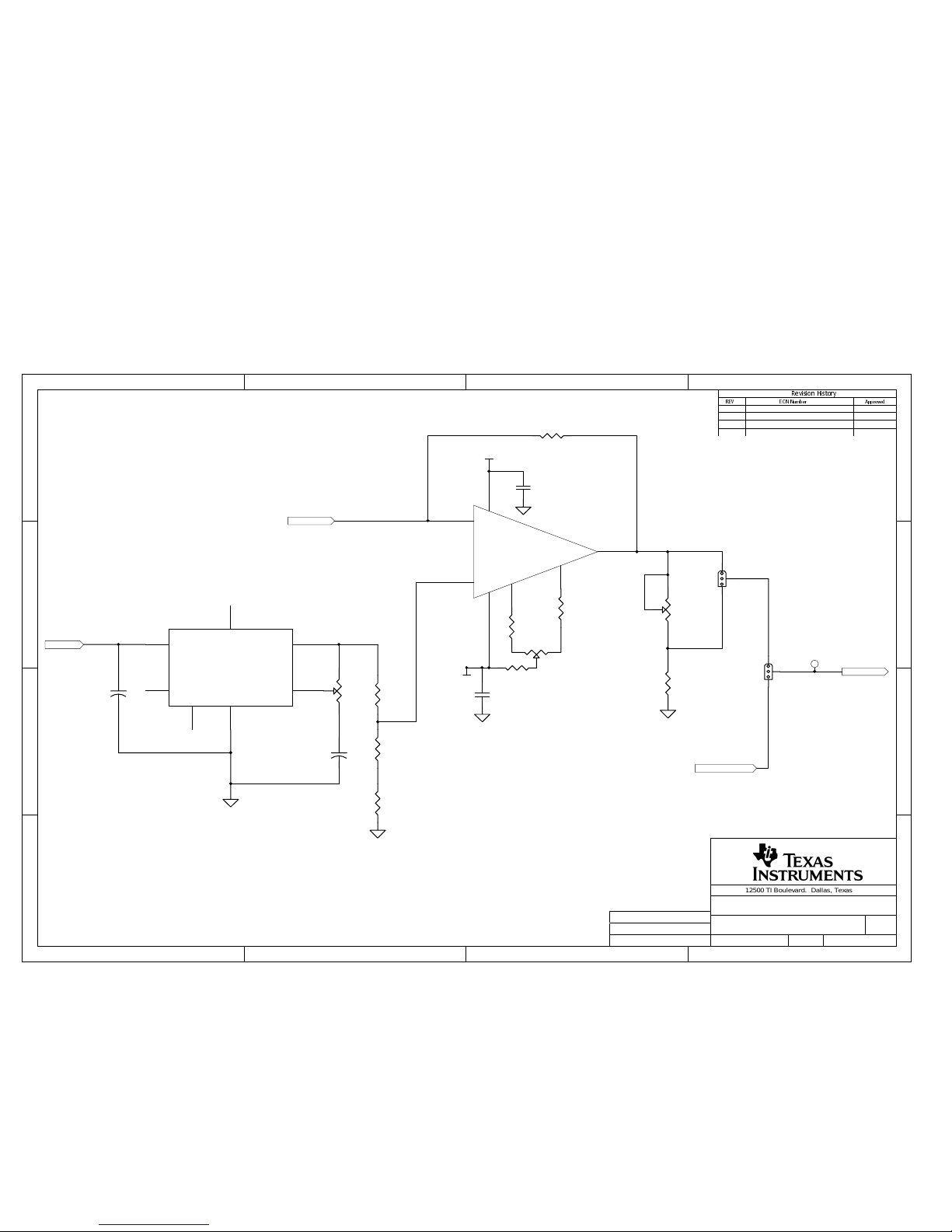
Reference DATE: 28-Nov-2001
Reference
6430333
A4
+VIN
VREFPW16
EXT_REFP
TP10
RV9
10k
R29
10K
W17
R66
4k
R65
6k
R67
10K
+Vin
2
NR
8
REF GND
7
GND
4
TRIM
5
Vout
6
Temp
3
U7 V RE3050
+
C30
2.2uF
+
C38
2.2uF
RV7
10k
SENSE
+Vs
-Vs
C45
0.1uF
C46
0.1uF
Vout
6
V+
7
Trim
1
Trim
5
-In
2
+In
3
V-
4
U11
TLE2081
R20
0
R23
0
RV10
100K
R50
5K
F 040500
R25
Not Installed
Joe Purvis
Joe Purvis
Page 35
1 2 34
A
B
C
D
4
321
D
C
B
A
5HYLVLRQ+LVWRU\
5(9 (&11XPEHU $SSU RYHG
12500 TI Boulevard. Dallas, Texas 75243
TITLE:
SHEET: OF:
FILE: SIZE:
REV:
Drawn By:
Engineer:
DOCUMENT C ONTROL # :
514
ADC DATE: 28-Nov-2001
ADC
6430333
A4
In_0
ADC_Data_out
C19
10uF
C22
0.1uF
+AVdd
VREFP
SENSE
R19
0
In_1
W10
W12
CS* or CS*/FS
1
Vref
2
AGND
3
AIN or AIN 0 or AIN(+)
4
SCLK or AIN1 or AIN(-)
5
VDD
6
FS or SCLK
7
SDO
8
U5
LCL_CLKX
FS
LCL_CS_ADC*
SOCKETED ADC
C23
10uF
C14
0.1uF
C47
0.01uF
1
2
3
4
5
6
7
8
U501
ADC_REF
ADC_REF
AIN0
AIN1
AIN0
AIN1
MSOP ADC
R10
10K
C1
100pF
+DVdd
0405002
1 2
3 4
5 6
7 8
J10
Joe Purvis
Joe Purvis
Page 36
1 2 34
A
B
C
D
4
321
D
C
B
A
5HYLVLRQ+LVWRU\
5(9 (&11XPEHU $SSU RYHG
12500 TI Boulevard. Dallas, Texas 75243
TITLE:
SHEET: OF:
FILE: SIZE:
REV:
Drawn By:
Engineer:
DOCUMENT C ONTROL # :
614
DAC DATE: 28-Nov-2001
DAC
6430333
A4
AOUT_A
VREFP
DAC_Data_in
SCLK2CS*
3
FS/OUTA
4
OUT/OUTB
7
REF
6
AGND
5
Vcc
8
DIN
1
U8
SOCKETED DAC
W18
B204+
1
B203+
2
B202-
3
B201-
4
B2_OUT
5
B2_FLT
6
B2/SD
8
A201-
18
A2/SD
11
A202-
17
A203+
16
A2_OUT
13
A2_FLT14A204+
15
V2+
7
V2-
12
VREF2
9
GND
10
J9
W15
C41
10uF
C43
0.1uF
+AVdd
AOUT W19
OUTA
DAC_OUTA
DAC Out
OUT/OUTB
DAC_OUT
DAC Out
DAC_Write*
LCL_CS_DAC*
LCL_CLKX
W14
C32
0.1uF
C21
0.1uF
2
3
4
7
658
1
U801
DAC SOP(D)
+AVdd
REF
REF
+VS
-VS
R54
10K
R55
10K
2 040500
TP20
TP21
1 2
3 4
5 6
7 8
J11
Joe Purvis
Joe Purvis
Page 37
1 2 34
A
B
C
D
4
321
D
C
B
A
5HYLVLRQ+LVWRU\
5(9 (&11XPEHU $SSU RYHG
12500 TI Boulevard. Dallas, Texas 75243
TITLE:
SHEET: OF:
FILE: SIZE:
REV:
Drawn By:
Engineer:
DOCUMENT C ONTROL # :
714
Output conditioning DATE: 28-Nov-2001
DAC Output
6430333
A4
+Vs
-Vs
RV11
100K
R35
4.7K
C52
R31
NI
DAC_OUTA
OUTA
+Vs
-Vs
RV8
100K
R26
4.7K
C36
R22
NI
DAC_OUT
OUT/OUTB
R21
0
R34
0
C40
0.1uF
C48
0.1uF
C49
0.1uF
C39
0.1uF
Vout
6
V+
7
Trim
1
Trim
5
-In
2
+In
3
V-
4
U9
R27
0
R28
0
R51
5K
Vout
6
V+
7
Trim
1
Trim
5
-In
2
+In
3
V-
4
U12
TLE2081
R30
0
R32
0
R33
0
2
040500
Joe Purvis
Joe Purvis
Page 38
1 2 34
A
B
C
D
4
321
D
C
B
A
5HYLVLRQ+LVWRU\
5(9 (&11XPEHU $SSU RYHG
12500 TI Boulevard. Dallas, Texas 75243
TITLE:
SHEET: OF:
FILE: SIZE:
REV:
Drawn By:
Engineer:
DOCUMENT C ONTROL # :
814
User connectors DATE: 28-Nov-2001
User Connectors
6430333
A4
CLKX
DX
FSX
XF
DR
FSR
1 2
3 4
5 6
7 8
9 10
11 12
13 14
15 16
17 18
19 20
J13
1 2
3 4
5 6
7 8
9 10
11 12
13 14
15 16
17 18
19 20
21 22
23 24
25 26
27 28
29 30
31 32
33 34
35 36
37 38
39 40
41 42
43 44
45 46
47 48
49 50
51 52
53 54
55 56
57 58
59 60
61 62
63 64
65 66
67 68
69 70
71 72
73 74
75 76
77 78
79 80
J16
1 2
3 4
5 6
7 8
9 10
11 12
13 14
15 16
17 18
19 20
21 22
23 24
25 26
27 28
29 30
31 32
33 34
35 36
37 38
39 40
41 42
43 44
45 46
47 48
49 50
51 52
53 54
55 56
57 58
59 60
61 62
63 64
65 66
67 68
69 70
71 72
73 74
75 76
77 78
79 80
J17
+5v
Peripheral & Control ConnectorMemory Interface Connector
+5v
+3.3v
CLKX
FSX
CLKR
+3.3v
FSR
XF
DX
DR
TOUT
CLKS
FB8
BLM11A121SGPB
FB10
BLM11A121SGPB
FB7
BLM11A121SGPB
FB6
BLM11A121SGPB
XF
FB9
BLM11A121SGPB
FB4
BLM11A121SGPB
FB12
BLM11A121SGPB
CLKX
FB11
BLM11A121SGPB
FB5
BLM11A121SGPB
DX
DSP_CLKX
DSP_FSX
FSX
DSP_CLKR
DSP_FSR
CLKR
DSP_XF
DSP_DX
DR
DSP_DR
DSP_TOUT
FSR
DSP_CLKS
TOUT
CLKR
1 2
3 4
5 6
7 8
9 10
11 12
13 14
15 16
17 18
19 20
J12
1 2
3 4
5 6
7 8
9 10
11 12
13 14
15 16
17 18
19 20
J15
PCI_GND
F 040500
CLKS
Joe Purvis
Joe Purvis
PCI_+12V
PCI_-12V
TOUT
CLKS
PCI_+5V
Page 39

1 2 34
A
B
C
D
4
321
D
C
B
A
5HYLVLRQ+LVWRU\
5(9 (&11XPEHU $SSU RYHG
12500 TI Boulevard. Dallas, Texas 75243
TITLE:
SHEET: OF:
FILE: SIZE:
REV:
Drawn By:
Engineer:
DOCUMENT C ONTROL # :
914
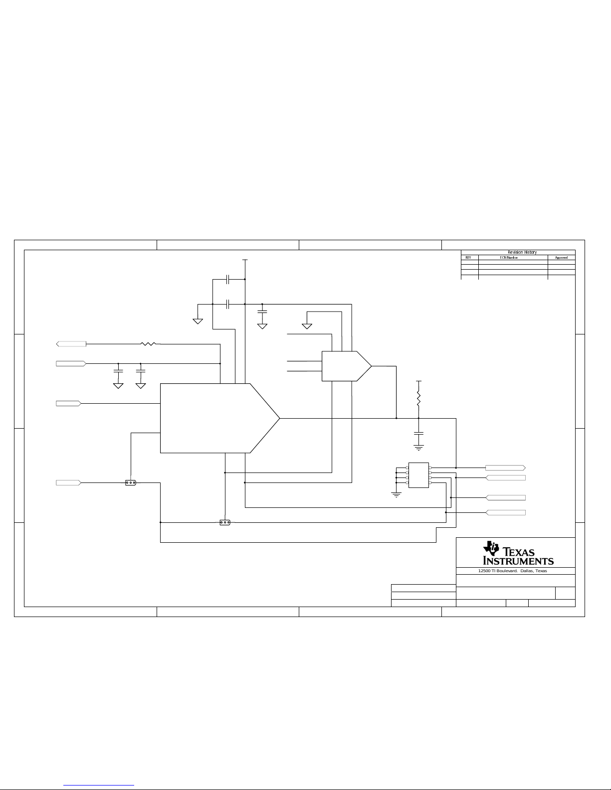
Digital Interface DATE: 28-Nov-2001
Digital Interface
6430333
A4
DSP_DX
DSP_XF
ADC_Data_out
DSP_TOUT
R40
33
DSP_FSX
DSP_FSR
DSP_CLKR
J14
DSP_CLKS
R46
49.9K
DAC_Data_in
DSP_CLKX
DSP_DR
+DVdd
SAM*
SYSCLK
R43
33
DSP_FSX
+DVdd
R45
33
W22
R44
33
Out
8
In
1
SW1A
Out
7
In
2
SW1B
Out
6
In
3
SW1C
+DVdd
DAC_Type
Out5In
4
SW1D
R38
1K
R37
1K
C65
0.1uF
OE
1
GND4OUT
5
VCC
8
X1
FS
LCL_CS_DAC*
LCL_CS_ADC*
LCL_CLKX
DSP_XF
DSP_DX
DSP_CLKX
DSP_FSX
DSP_DR
DSP_FSR
DSP_CLKR
DSP_CLKS
DSP_TOUT
DSP_TOUT
DSP_CLKS
DSP_CLKR
DSP_FSR
DSP_CLKX
DSP_DX
DSP_XF
DSP_DR
DSP_FSX
DAC_Write*
TO / FROM USER
CONNECTIONS
TO / FROM ADC
TO DAC
W23
W20
W21
SYSCLK
W24
EVM_CLKX
R71
33
EVM_CLKX
C64
0.01uF
D4
D3
SYSCLK
+DVdd
R6
430
D5
LCL_CS_ADC*
DSP_DR
DSP_DX
DSP_XF
DAC_Data_in
LCL_CLKX
SAM*
DSP_FSX
FS
ADC_Data_out
LCL_CS_DAC*
DAC_Write*
SYSCLK
DAC_Type
EVM_CLKX
MOM
Stand Alone Mode
MOM*
R56
430
R11
1K
R57
430
Joe Purvis
Joe Purvis
EVM-0309R2.DDB
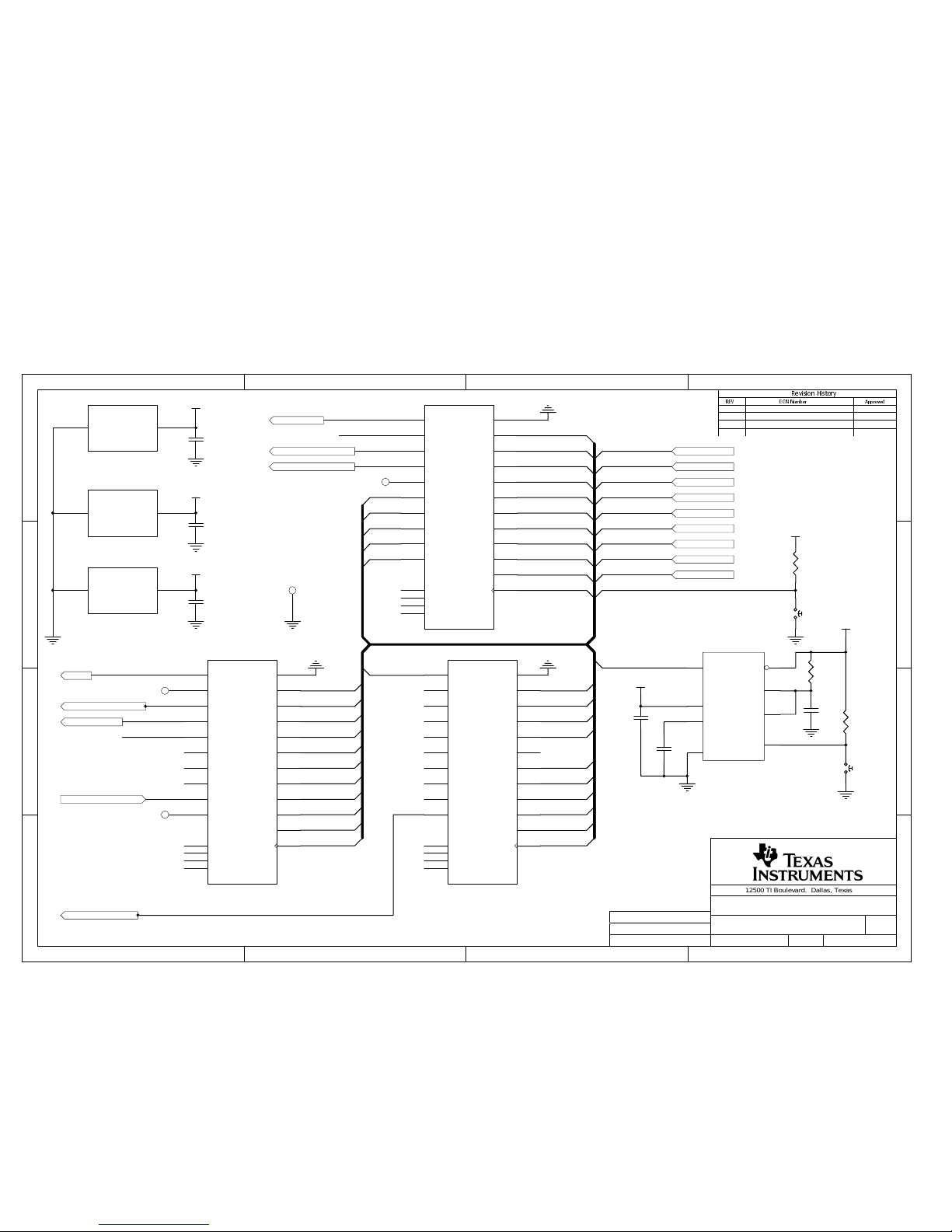
Page 40
1 2 34
A
B
C
D
4
321
D
C
B
A
5HYLVLRQ+LVWRU\
5(9 (&11XPEHU $SSU RYHG
12500 TI Boulevard. Dallas, Texas 75243
TITLE:
SHEET: OF:
FILE: SIZE:
REV:
Drawn By:
Engineer:
DOCUMENT C ONTROL # :
10 14
Stand Alone Mode DATE: 28-Nov-2001
Stand Alone
6430333
A4
LCL_CS_ADC*
DSP_DR
DSP_DX
DSP_XF
SAM* DSP_DX
DSP_XF
DAC_Data_in
ADC_Data_out
DAC_Data_in
ADC_CS*
ADC_Data_out
INIT*
+DVdd
RESET
RESET
SYSCLK
SYSCLK
ADC_TC*
ADC_TC*
RESET
DSP_DR
START*
SW2
+DVdd
INIT*
LCL_CLKX
SAM*
DSP_FSX
DSP_FSX
SW3
+DVdd
C62
C61
FS
SAM*
Q2
Q1
Q0
RESET
SYSCLK
DSP_XF
DSP_DX
DSP_FSX
ADC_Data_out
ADC_Data_n3
DSP_XF
DSP_FSX
Q2
Q1
Q0
ADC_Data_out
LCL_CS_DAC*
START*
I11
16
I10
13
I9
12
I8
11
I7
10
I6
9
I5
7
I4
6
I3
5
I2
4
I1
3
CLK/I0
2
I12/O0/Q0
17
I13/O1/Q1
18
I14/O2/Q2
19
I15/O3/Q3
20
I16/O4/Q4
21
I17/O5/Q5
23
I18/O6/Q6
24
I19/O7/Q7
25
I20/O8/Q8
26
I21/O9/Q9
27
NC
1
NC
8
NC
15
NC
22
U16A
I11
16
I10
13
I9
12
I8
11
I7
10
I6
9
I5
7
I4
6
I3
5
I2
4
I1
3
CLK/I0
2
I12/O0/Q0
17
I13/O1/Q1
18
I14/O2/Q2
19
I15/O3/Q3
20
I16/O4/Q4
21
I17/O5/Q5
23
I18/O6/Q6
24
I19/O7/Q7
25
I20/O8/Q8
26
I21/O9/Q9
27
NC
1
NC
8
NC
15
NC
22
U13A
I11
16
I10
13
I9
12
I8
11
I7
10
I6
9
I5
7
I4
6
I3
5
I2
4
I1
3
CLK/I0
2
I12/O0/Q0
17
I13/O1/Q1
18
I14/O2/Q2
19
I15/O3/Q3
20
I16/O4/Q4
21
I17/O5/Q5
23
I18/O6/Q6
24
I19/O7/Q7
25
I20/O8/Q8
26
I21/O9/Q9
27
NC
1
NC
8
NC
15
NC
22
U14A
DSP_FSX
DSP_XF
Q0
Q1
Q2
DAC_Write*
SYSCLK
SYSCLK
DAC_Type
DAC_Type
DAC_Type
Q3
Q3
Q3
R42
10K
R39
10K
R41
10K
C60
0.1uF
Vcc
28
GND
14
U16B
Vcc
28
GND
14
U13B
Vcc
28
GND
14
U14B
+DVdd
C63
0.1uF
C55
0.1uF
C54
0.1uF
+DVdd
+DVdd
RESET
4
DISCH
7
THRES
6
TRIG
2
CONT
5
VCC
8
GND
1
OUT
3
U10
NE555D
EVM_CLKX
EVM_CLKX
EVM_CLKX
TP14
TP15
TP17
TP19
MOM
MOM
MOM
MOM
DAC_Type
DAC_Type
ADC_Data_n3
START
RESET
Joe Purvis
Joe Purvis
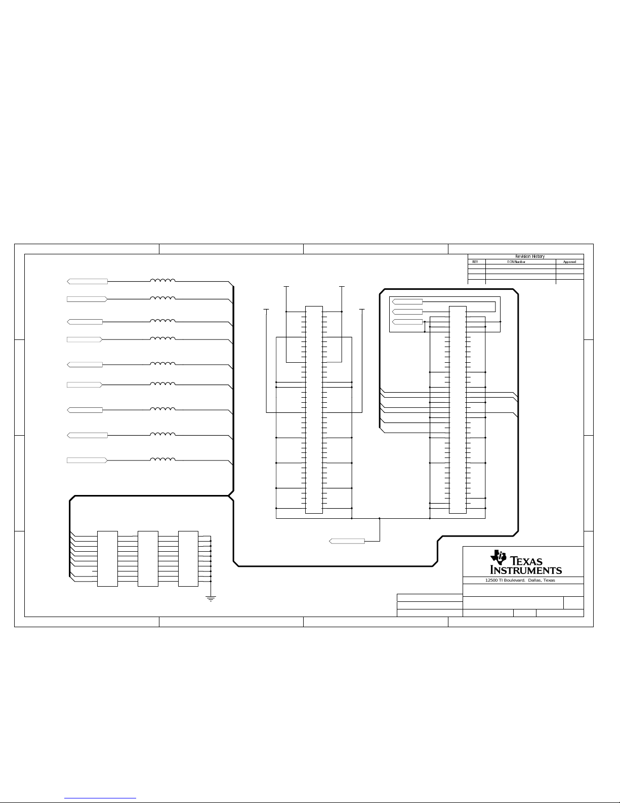
Page 41

1 2 34
A
B
C
D
4
321
D
C
B
A
5HYLVLRQ+LVWRU\
5(9 (&11XPEHU $SSU RYHG
12500 TI Boulevard. Dallas, Texas 75243
TITLE:
SHEET: OF:
FILE: SIZE:
REV:
Drawn By:
Engineer:
DOCUMENT C ONTROL # :
11 14
Input configuration DATE: 28-Nov-2001
Input Configuration
6430333
A4
W1
BNC_0
IDC_0
B204+
1
B203+
2
B202-
3
B201-
4
B2_OUT
5
B2_FLT
6
B2/SD
8
A201-
18
A2/SD
11
A202-
17
A203+
16
A2_OUT
13
A2_FLT
14
A204+
15
V2+
7
V2-
12
VREF2
9
GND
10
J3
W5
BNC_1
IDC_1
Channel_1
-Vs
+Vs
Channel_0
Test signal 0
Test signal 1
Signal Generator
TP6
R12
33
C9
6800pF
TP7
R9
33
C8
6800pF
W3
BB_Output_1
IN_1
Prototype Area
W8
W6
BB_Output_0
IN_0
Prototype Area
IN_0 OUT_0
Signal Conditioning
W7
W2
OUT_1
IN_1
Signal Conditioning
W4
W11
W25
2 040500
Joe Purvis
Joe Purvis
Page 42

1 2 34
A
B
C
D
4
321
D
C
B
A
5HYLVLRQ+LVWRU\
5(9 (&11XPEHU $SSU RYHG
12500 TI Boulevard. Dallas, Texas 75243
TITLE:
SHEET: OF:
FILE: SIZE:
REV:
Drawn By:
Engineer:
DOCUMENT C ONTROL # :
12 14
Signal Generator DATE: 28-Nov-2001
Signal Gene rator
6430333
A4
-Vs
+Vs
R60
49.9K
C17
1nF
+Vs
+Vs
Test Signal 0
Sine Out
2
Triangle Out
3
Square Out
9
V+
6
Duty adj.
5
Duty Adj.
4
Timing Cap.
10
V- / GND
11
Sine Adj
1
Sine Adj
12
FM Bias
7
FM Sweep Input
8
Not connected
13
Not Connected
14
U3
ICL8038
R72
49.9K
W9
RV3
100K
R7
4.7K
C13
0.1uF
C12
0.1uF
+
C6
10uF
C5
0.1uF
C15
0.1uF
-Vs
RV4
10K
TP5
+Vs
Test Signal 1
RV6
100K
R15
4.7K
C7
0.1uF
-Vs
RV5
10K
TP8
3
2
1
8 4
U4A
TLE2082D
5
6
7
U4B
TLE2082D
C16
0.1uF
-Vs
+
C18
10uF
R16
4.7K
R61
4.7K
R59
4.7K
R13
4.7K
R5
4.7K
R8
4.7K
2 040500
Joe Purvis
Joe Purvis
Page 43

1 2 34
A
B
C
D
4
321
D
C
B
A
5HYLVLRQ+LVWRU\
5(9 (&11XPEHU $SSU RYHG
12500 TI Boulevard. Dallas, Texas 75243
TITLE:
SHEET: OF:
FILE: SIZE:
REV:
Drawn By:
Engineer:
DOCUMENT C ONTROL # :
13 14
Prototype Area DATE: 28-Nov-2001
Prototype Area
6430333
A4
BB_Output_1IN_1
BB_Output_0IN_0
TP1 TP2
TP3 TP4
1
2
3
4
5
6
7 8
9
10
11
12
13
14
PT1
2 040500
Joe Purvis
Joe Purvis
Page 44

1 2 34
A
B
C
D
4
321
D
C
B
A
5HYLVLRQ+LVWRU\
5(9 (&11XPEHU $SSU RYHG
12500 TI Boulevard. Dallas, Texas 75243
TITLE:
SHEET: OF:
FILE: SIZE:
REV:
Drawn By:
Engineer:
DOCUMENT C ONTROL # :
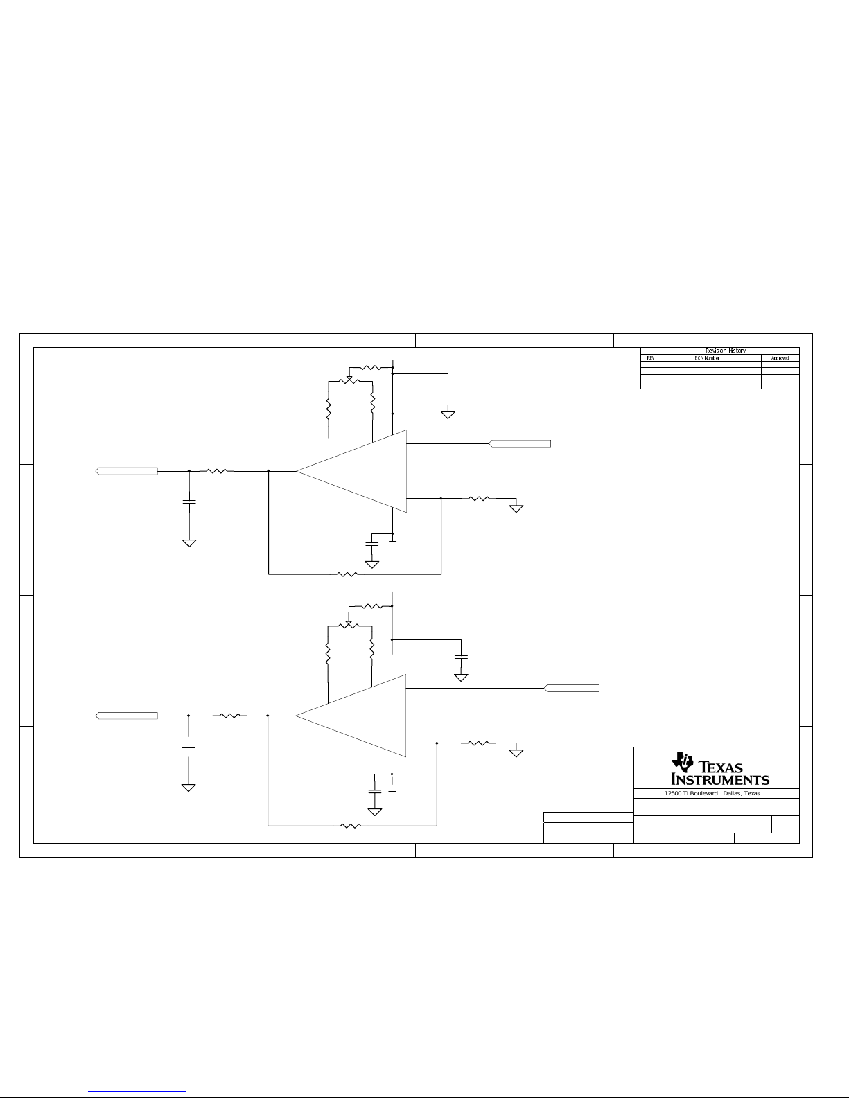
14 14
Signal Conditioning DATE: 28-Nov-2001
Signal Conditioning
6430333
A4
OUT_1
IN_1
R3
NI
R4
0
-Vs
+Vs
RV2
100K
OUT_0
IN_0
R1
NI
R2
0
-Vs
+Vs
RV1
100K
C37
0.1uF
C4
0.1uF
C2
0.1uF
C3
0.1uF
Vout
6
V+
7
Trim
1
Trim
5
-In
2
+In
3
V-
4
U2
TLE2081
R36
0
R47
0
R52
5K
Vout
6
V+
7
Trim
1
Trim
5
-In
2
+In
3
V-
4
U1
TLE2081
R48
0
R49
0
R53
5K
F 040500
Joe Purvis
Joe Purvis
 Loading...